Connections Fourth Quarter 2012
5
SA N F R A NCISCO/OA K L A N D
B A Y
PAGE
B R
I
D G E
SELF-ANCHORED-SUSPENSION SPAN
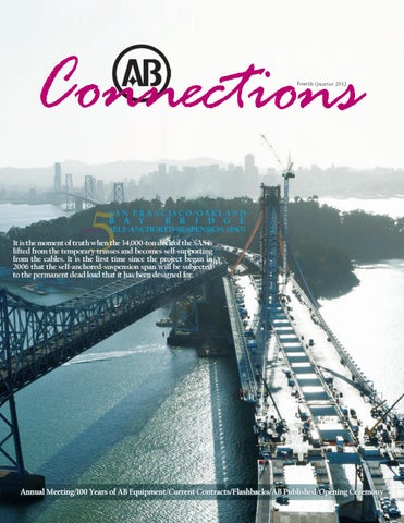
It is the moment of truth when the 34,000-ton deck of the SAS is lifted from the temporary trusses and becomes self-supporting from the cables. It is the first time since the project began in 2006 that the self-anchored-suspension span will be subjected to the permanent dead load that it has been designed for.
Annual Meeting/100 Years of AB Equipment/Current Contracts/Flashbacks/AB Published/Opening Ceremony
Connec tion s 12
5
AB EQUIPMENT
AB innovations and “in it for the long run” investments
SAN FRANCISCO/OAKLAND BAY BRIDGE SELF-ANCHORED-SUSPENSION SPAN
16
ANNUAL MEETING
The 2012 annual meeting welcomed new board members and congratulated an AB employee for her 25 years of service
18
HR/WELLNESS
Wellness program updates for the coming months and information on your open enrollment
19
The completion of an AB-built bridge prompts the retirement of a 220-year-old historic ferry
Connections
21
Fourth Quarter 2012
5
SA N F R A NCISCO/OA K L A N D
B A Y
PAGE
B R
I
FLASHBACKS
C
D G E
SELF-ANCHORED-SUSPENSION SPAN
It is the moment of truth when the 34,000-ton deck of the SAS is lifted from the temporary trusses and becomes self-supporting from the cables. It is the first time since the project began in 2006 that the self-anchored-suspension span will be subjected to the permanent dead load that it has been designed for.
Annual Meeting/100 Years of AB Equipment/Current Contracts/Flashbacks/AB Published/Opening Ceremony
O
V
E
R
Six years into the project, the selfanchored-suspension-span of the new San Francisco/Oakland Bay Bridge is being put to the test. The 34,000 M ton OBG deck has been supported by the massive temporary works (or falsework; which is a project within a project) will now be self-supporting
AB PUBLISHED
AB’s role on the iconic Golden Gate Bridge
22 PROJECT CEREMONY FL governor boasts AB’s Berth 12 project is expected to create over 775 jobs
To watch the video related to the featured load transfer article in this issue, posted by the owner (CALTRANS) of ABFJV’s San Francisco/Oakland Bay Bridge, visit: http://baybridgeinfo.org/projects/sas
T H A N K YOU Much appreciation to the following individuals for their contribution to this issue: All ARTBA photo contest participants, Mike Cegelis, Ugo DelCostello, Paul Michalak, Adam Roebuck, Kevin Smith, Scott Tudor NEW HIRES
by Kad i Cam ard ese
Please contact the Communications and Marketing Department with news and inquiries: kcamardese@americanbridge.net
Taryn Skalski, Field Engineer, U.S. 190 Mississippi River Bridge, Baton Rouge, Louisiana Timothy Popham, Field Engineer, Las Vegas High Roller, Nevada John Henderson, Marine Works Department Manager, Forth Replacement Crossing, Edinburgh, Scotland David Kilburn, Senior Temporary Works Designer, Forth Replacement Crossing, Edinburgh, Scotland Daniel Patterson, Field Engineer, Columbus Road Lift Bridge, Cleveland, Ohio Scott Ranieri, Payroll Supervisor, Headquarters, Coraopolis, Pennsylvania
CURR EN T CON TR ACTS
Manufacturing BNR/Tertiary WWTP Project, Modesto, CA Queens Ridge Vibration Upgrade, Las Vegas, NV I-84 Bridges over Center Street, Newtown, CT Symphony Park Pedestrian Bridge, Las Vegas, NV Bellevue Access Road Bridge, Bellevue, OH Edna Maguire Elementary School, Mill Valley, CA SAS OBG Cable Safety Railing CCO 188, Oakland, CA I-80 Bridges Group Two, Clarion and Venango Counties, PA Emsworth Lock and Dam, Neville Island, PA Harold Structures, NYC Unicorn Bridge Rehabilitation, NYC Walt Whitman Bridge Rehabilitation, Philadelphia, PA Walt Whitman Bridge Runway, Philadelphia, PA Clearfield County Plate Girder Bridge, Kylertown, PA Shore Parkway, Queens, NY Sun Valley Bridge Widening, Los Angeles, CA 4th Avenue Bridge, Johnstown, PA George Washington Bridge Deck Replacement, NYC I-80 Bridges, Clarion County, PA Trinity County Bridges, Trinity County, CA Mansfield Bridge Rehabilitation, Allegheny County, PA Ambridge/Aliquippa Bridge Rehabilitation, Beaver County, PA Blacklegs Creek Bridge, Indiana County, PA Columbus Road Lift Bridge, Cleveland, OH East Pine Street Bridge, Snyder County, PA Cherry Tree Bridge, Indiana County, PA SAS Barrier Transition, Oakland, CA Edward A. Silk Memorial Bridge, Cambria County, PA Runk Bridge, Huntingdon, PA East Clinton Street Bridge, Ithaca, NY Rensselaer Street Bridge, Rensselaer Falls, NY Fuller Road Bridge, Albany, NY Squirrel Hill Tunnel Rehabilitation, Pittsburgh, PA Milwaukee Light Rail, Portland, OR Bronx River Parkway, Greenburgh, NY
Pittsburgh Charleroi-Monessen Bridge Replacement, Charleroi, PA Columbus Road Lift Bridge, Cleveland, OH U.S. 190 Mississippi River Bridge Repairs, Baton Rouge, LA Special and International Projects Forth Replacement Crossing, Scotland, United Kingdom Las Vegas High Roller Observation Wheel, NV Richmond Pier R3 Repairs, Yorktown, VA Wrightsville Beach Bridge, Wrightsville, NC Bridge No. 30 - U.S. 421, Wilmington, NC Explosives Handling Wharf No. 2, Silverdale, WA Bonner Bridge No. 11 Scour Protection, Dare County, NC Western ABFJV San Francisco/Oakland Bay Bridge, CA Tampa Platt Street Bridge Major Repairs, Tampa, FL Courtney Campbell Design/Build Pedestrian Bridge, Tampa, FL Tom’s Harbor Channel Bridge Repair, Duck Key, FL Golden Beach Bridge Replacement, Golden Beach, FL Berth 12 Wharf Extension and Container Terminal, Palmetto, FL Kansas City Hurricane Deck Bridge, Camdenton, MO New York Walt Whitman Deck Replacement, Philadelphia, PA George Washington Bridge Rehabilitation, New York City Manufacturing continued ... SAS Customer Change Orders, Oakland, CA: 85 Elevator Safety Enclosures 204 Stiffener Angle Retro-fit 189 Bike Path Rail Modifications 120 Restraint Brackets 245 Hinge K. Steel Ballast 223 Split Collar Modifications 241 Hinge K. Soffit Openings
IRONWORKER HALL OF FAME AB Employee Inducted into the Ironworker Hall of Fame On August 10, 2012 Dallas Compeau was inducted into the Ironworker Hall of Fame in Mackinaw City, MI during the ceremony at the Annual International Ironworker Festival. Dallas has been in the ironworker industry for over 35 years, many of which he has spent with American Bridge. Most recently, he has run AB’s work on the Williams Gas Pipeline Bridge and the Coosa River Suspension Bridge Rehabilitation near Clanton, AL. American Bridge is proud to have employees, such as Dallas, who are the best in the industry. Congratulations from everyone at AB. www.americanbridge.net
Iron Worker Statue in Mackinaw City, MI with the Straits of Mackinac Bridge, completed by American Bridge in 1957, in the background
AB Connections, Fourth Quarter 2012
3
PHOTO CONTEST You don’t have to be a professional to take fantastic pictures; you just need to have your camera (or smartphone) in the right place at the right time. Each year the AB Marketing and Communications Department participates in a few photo contests and appreciates the high response from AB employees in the field. Here are a few of our favorites from the latest submittal:
San Francisco/Oakland Bay Bridge SelfAnchored-Suspension Span by Arne Roen
Sherman Minton Bridge Girder Repairs by Joe Stilson
Las Vegas High Roller by Larry Lou
San Francisco/Oakland Bay Bridge Self-Anchored-Suspension Span by Zach Lauria
Walt Whitman Bridge - Suspension Spans and Anchorage Spans Deck Replacement by Bruce Phillips
American Road & Transportation Builders Association (ARTBA), 9th annual Look Through the Lens Contest: 2012
4
AB Connections, Fourth Quarter 2012
www.americanbridge.net
SAS
San Francisco/Oakland Bay Bridge The moment of truth: SAS deck lifted from the temporary trusses and becomes self-supporting from the cables and subjected to the permanent dead load for which it was designed
Temporary Works Demolition Contribution by Scott Tudor, P.E., AB Senior Design Engineer
project team Eric Blue, Field Engineer Kelvin Chen, Field Engineer Paul Fikse, Design Engineer Levi Gatsos, Design Engineer Katherine Quillin, Senior Field Engineer Scott Tudor, P.E., Senior Design Engineer
www.americanbridge.net
Over 25,000 tons of temporary steel falsework was used on the new San Francisco/Oakland Bay Bridge Self-AnchoredSuspension (SAS) project to support the permanent orthotropic bridge deck (OBG). The falsework was utilized throughout construction until recently when the self weight of the OBG was transferred from the temporary support cradles to the main suspension cables during the load transfer process. The unloading of the cradles and supporting falsework marked the end of the need for the temporary works and triggered the beginning of the falsework demolition phase. July 2012 marked the beginning of this phase, as the four east end cradles that had supported OBG lifts 13 and 14 were removed in preparation for load transfer. Since the cradles were directly underneath the OBG, access was limited and tight clearances prohibited a crane to lift the cradles out directly.
AB Connections, Fourth Quarter 2012
5
Cradle 13E loaded, prior to removal
Removal Beam setup under eastbound OBG
Cradle 14E being tripped up using a barge mounted Series-3 Ringer, as seen from below
Cradle 14E being tripped up using a barge mounted Series-3 Ringer, as seen from above
Cradle 13W getting pulled out from underneath westbound OBG
A pair of W24 by 192 “removal beams”, braced by American Bridge F130/131 falsework diagonals, were staged on the temporary truss and cantilevered outside the limits of the OBG. Each east end cradle was positioned over the removal beams and slid outboard using a pair of electric winches. The sliding surface consisted of stainless steel on 1” UHMW (plastic). Once the cradles were slid out far enough to clear the face of the OBG, rigging from a barge mounted 4100W Series-3 Ringer was attached. Each cradle was tripped vertically and removed by sliding the cradles from underneath the OBG while taking load with the crane. Each cradle was then lowered to a scrap barge below and tripped back to a horizontal position. This was a delicate operation as the temporary cradles came within inches of the permanent bridge.
Cradle 13W being pulled out from underneath the bridge; San Francisco in the background
For the demolition The load transfer process involves over 25,000 of the remaining cradles that tons of temporary falsework supporting the support OBG lifts OBG being transferred from the temporary 1-12, a removal beam support cradles to the main suspension cables. setup was once again constructed. However, due to the presence of a bike path on the eastbound deck and counterweight boxes on the westbound deck, the removal beams would have needed to extend much further in order for a barge mounted crane to reach the cradles. Instead, the removal beams were installed so that they would point inboard towards the center of the bridge. Once a cradle is pulled out from underneath the OBG, an 888 Series-1 Crawler crane, positioned on the westbound bridge deck, then trips the cradle and lowers it to a barge. The crawler crane is positioned strategically such that it can reach both the eastbound and westbound cradles. Cradle demolition is scheduled to be completed in January 2013. Once all the cradles are removed, demolition of the continuous Cradle 13W being lowered to the scrap barge temporary truss, towers and foundations can commence.
Cradle 13W being tripped up with barge mounted ringer
6
AB Connections, Fourth Quarter 2012
www.americanbridge.net
LOAD TRANSFER Contribution by Kevin Smith, P.E., AB Technical Director and Adam Roebuck, P.E., AB Assistant Cable Project Manager
Early in the project the load transfer of the San Francisco/Oakland Bay Bridge selfanchored-suspension span (SAS) became known as “the miracle�. It is the moment of truth when the deck of the SAS is lifted from the temporary trusses and becomes selfsupporting from the cables. It is the first time that the SAS will be subjected to the permanent dead load that it has been designed for.
project team
Eric Blue, Field Engineer Danny Dunn, Superintendent Levi Gatsos, Field Engineer Ben Jones, Field Engineer Jerry Kent, General Superintendent Bob Kick, Operations Manager Zach Lauria, Field Engineer Andre Markarian, Field Engineer Brian Petersen, Project Director Katherine Quillin, Senior Field Engineer Adam Reeve, Field Engineer Adam Roebuck, Assistant Cable Project Manager Ankur Singh, Fluor Field Engineer Kevin Smith, Technical Director Scott Smith, Superintendent Scott Yeager, Assistant Cable Project Manager
www.americanbridge.net
AB Connections, Fourth Quarter 2012
7
In a normal suspension bridge (such as the existing west span of the Bay Bridge or the Golden Gate Bridge), the cables are terminated into large concrete gravity anchors that resist their large tension forces. There are also examples of direct rock anchorage of suspension cables. In the case of this self-anchoredsuspension bridge, the main cable anchors into the bridge deck itself, pulling it into compression. The axial stiffness in the bridge deck resists the compressive forces imparted by the main cable. To account for the anticipated axial shortening that will occur from these compressive forces, the length of the orthotropic box girder 2009 (OBG) was cambered 295mm long. The box girder was also cambered vertically to achieve the required profile under the dead load condition and introduce dead load moment into the box girder. The dead load moment is negative in sign which applies tension in the top deck plate of the OBG. The addition of tension in the top deck plate counters and thereby reduces the dead load axial compression, which 2010 is necessary to provide the capacity to support local wheel loads on the top deck plate. “The miracle� occurs after load transfer when these design assumptions are realized and the 36,800MT bridge deck is supported from the main cable at the correct profile, and once the axial shortening of the 614m long bridge falls within the required tolerance of just 0.035m. 2011
8
AB Connections, Fourth Quarter 2012
www.americanbridge.net
Cable Compaction Following successful completion of strand hauling in April, the American Bridge/ Fluor Enterprises, Inc., Joint Venture (ABFJV) began the process of preparing for load transfer by compacting the main cable. Four compactors, each with a crew of ironworkers, were positioned in the four spans and worked their way downhill from the T1 tower. The compactors were mounted to a frame with plastic, conical wheels that permitted the machine to run smoothly down the cable. Each compactor contained six 300T jacks positioned radially around the cable. The ends of each jack contained a curved, 400mm wide shoe which forced the 137 individual strands into one 784mm diameter cable. Stainless steel strapping was then used to hold and maintain the cylindrical shape of the compacted cable.
Cable Band Erection Once compaction was complete, surveying crews laid out the individual cable band locations throughout the four spans. Three different pieces of machinery were used to erect the cable bands. Those cable bands low enough to the OBG were erected using either a 90T hydraulic or an 888-Crawler crane from the bridge deck. Cable bands on either side of the T1 tower were erected using the tower crane. The cable bands that could not be erected directly with a crane were attached to a highline system that spanned the length of the cable. A winch at the top of the T1 tower was used to pull or lower the cable band along the highline to the correct position. There are a total of 114 cable bands, each one being unique to account for variations in the cable slope and rotation. Cable bands are composed of two halves that are held together using a series of bolts. Depending on the slope of the main cable, the number of bolts in each cable band varies from six to 26. Lengths of cable bands vary from 908mm to 2816mm and weights from 1360kg to 5100kg. A typical cable band bolt is 2� in diameter and 665mm long. Because the cable bands were erected on the two-dimensional freehanging cable, it was necessary to camber the orientation of each cable band to account for the rotation that would occur in the final three-dimensional cable. Once the cable band was positioned to the proper orientation, each cable band bolt was fitted with a center-hole jack; the jacks were manifolded together, the bolts were brought up to the specified tension and the nuts were run tight to provide a tight grip on the cable sufficient to carry the loads imparted by the suspender ropes. www.americanbridge.net
AB Connections, Fourth Quarter 2012
9
Suspender Erection Suspender rope erection followed installation of the cable bands. Each of the 100 cable bands with suspenders has one uphill and one downhill suspender, and every one of the 200 suspenders has a unique length. Lengths of the suspender ropes vary from as short as 5.229m to as long as 207.722m. The shorter suspender ropes, those that straddle cable bands closest to the OBG, were erected using a hydraulic crane. The longer suspender ropes were erected directly off of the spools they were delivered on. The spool containing the suspender rope was positioned on a reel stand beneath the cable band that was to receive that rope. A system of rollers (also referred to as a battery) was positioned on the uphill side of the cable band receiving the suspender. A winch line was run from the reel stand up and over the battery and down again to grab the socketed end of the suspender rope. The winch line was then reeled back into the winch, thus pulling the suspender rope up and over the main cable. During fabrication, the center of each suspender rope was marked; during installation, that center mark was used to align the suspender rope into its proper position in a saddle cast into the cable band.
Main Cable Swing Out To address the close proximity between the free-hanging main cable and a portion of the OBG at the east end of the bridge, the outboard corner assemblies of OBG lifts 12E and 12W were fabricated with a field splice. While this provided the clearance to enable the cables to be erected, the corner assemblies were required to be in place prior to commencing load transfer to resist the axial loads imparted to the OBG. ABFJV’s solution was to perform a “swing out” of the main cable. In order to perform swing out, four Vierendeel trusses, extending up to 40’ outboard of the OBG, were bolted to the suspender brackets at panel points 104 and 106. A 3” diameter high strength all-thread rod with custom ABFJV designed universal joints at each end spanned the distance between a U-bracket placed around the main cable and a jacking assembly bolted to the outboard end of the trusses. A 200T jack was then used at each truss to laterally displace the main cable the required 5.4m. With the cable in the “swung” geometry, the cable east of PP 106 could be compacted and the corner assembly erected and welded.
10
AB Connections, Fourth Quarter 2012
www.americanbridge.net
Load Transfer With the preparatory work complete, on September 4, 2012, ABFJV started transferring the OBG weight from the temporary trusses into the suspender ropes and main cable. To perform this critical operation in the fastest way possible, ABFJV separated the load transfer into four phases. Phase-1 was the most significant of the phases and transferred about 93 percent of the dead load into the main cable and lifts the OBG off all of the cradles, except near the T1 tower and pier E2. The remaining seven percent of dead load cable tension comes from a 50mm thick epoxy-asphalt paving that is applied at the end of the project. Phase-2 and phase-4 of load transfer sequenced the tensioning of the suspender ropes near the T1 tower and the main cable connection to cable brackets near pier E2 to occur after phase-1 of load transfer. The timing of these two phases allows for redistribution of forces in the main cable wires to occur as the main cable
deflects 9m laterally and 4m vertically from the two-dimensional free-hanging geometry to the three-dimensional final geometry. Load transfer phase-3 also proceeded after phase-1, connecting the remaining intermediate suspenders. Phase-1 of load transfer was accomplished by jacking 52 of the 100 suspender ropes in a series of 18 steps. By engaging about half of the suspenders in this phase, load transfer could be completed faster with less equipment. During phase-1, the forces and geometry of the bridge and cable changed significantly. ABFJV actively monitored and collected data for the suspender jacking distances and loads, jacking saddle adjustments, tower tie-back movements and loads, cable band bolt tension measurements, pier E2 temporary bearing movement, East Saddle rocking movement and cradle disengagement. This data was evaluated throughout load transfer to ensure that the forces in the bridge were balanced without overloading any part of the structure.
Load transfer phase-1
www.americanbridge.net
AB Connections, Fourth Quarter 2012
11
Suspender Rope Jacking Two 4.5”thick steel plate weldments, with a full-length zinc lined semicircle machined into them, were fixed to the lower end of the suspender rope with eighteen 1.25” diameter A490 bolts. Four of these assemblies, referred to as friction clamps, were capable of supporting the maximum load transfer design load of 7000kN. The friction clamps were connected to a lower jacking beam with four 3” diameter high strength all-thread rods. To accommodate the three dimensional movements during load transfer and to equalize the load in the four suspender parts, the friction clamps were designed with equalizer pins in two directions and the lower jacking beam utilized a rocker and two manifolded 400T jacks. The friction clamps, threaded rods and jacking beams temporarily supported the load until the suspender ropes were connected to the bridge.
Jacking Saddle Jacking As the suspenders were loaded in the main and side spans, the jacking saddle also had to be jacked to maintain equal tension in the main cable between the side span and the west loop. Using a total jacking capacity of 4800T (four 300T jacks on each of the four jacking saddle legs), the jacking saddle was separated from pier W2 and shim stacks were incrementally added throughout phase-1 to achieve the desired tension at each load transfer step. In all, the jacking saddle was pushed out a total of 1652mm, creating 23,500MT of tension in the main cable.
Elevation view: shims installed; after phase-1 of load transfer
12
AB Connections, Fourth Quarter 2012
www.americanbridge.net
Tower Tie-Back Release Prior to starting PWS hauling, ten 2.25” diameter strands were attached to the top of the tower, and twenty 150T jacks were used at the base of Yuerba Buena Island to pull the T1 tower 518mm to the west. Similar to the jacking saddle, the tie-back strands were gradually released during load transfer to allow the horizontal cable tensions between the main and side spans to equalize. Four weeks after the start of load transfer, “the miracle” occurred. Phase-1 of load transfer was complete, the OBG lifted off of the temporary supports, and the OBG shortened as expected. The expedited completion of load transfer phase-1 allowed for the early removal of the supporting cradles, connection to the adjacent YBITS and Skyway structures and final connection between pier E2 and the OBG. ”The miracle” is a testament to the years of planning the design, fabrication and erection of the SAS, which is now a bridge like no other.
www.americanbridge.net
AB Connections, Fourth Quarter 2012
13
AB SPECIALIZED EQUIPMENT Current AB generation benefits from 112 years of equipment design that has been seen on projects from Lisbon to Vancouver and just about everywhere in between By Ugo DelCostello, AB Superintendent and Michael Cegelis, AB Senior Vice President
For 112 years now, American Bridge has been a quality company that invests in its future. Our generation benefits in so many ways from the perspicacity of our forebears, and their willingness to make decisions for the long run continues to provide competitive advantage to the company today. Just a few examples: Our F1 Falsework System, designed by company engineers in the 1950s, provides a flexible and standardized system of temporary support. While this represented a large investment by the company at the time, it
Our Bridgebuilder Tugs were designed by the marine department of AB in the 1960s. These tugs are easily assembled and disassembled for transport, and are truckable. They deliver up to 600hp, and are workhorses on our bridge and marine projects that are characterized by heavy barge movement operations. They have been seen on our projects from Lisbon to Vancouver and just about everywhere in between. The investments represented by our American Bridge Engineers Handbook, American Bridge Standard Operating
If you haven’t taken advantage of the systems papers available on the AB Access site within your individual project, please review in detail and avail yourself of these competitive advantages. has lowered our cost structure and risk ever since. Our estimators can reliably cost the pre-engineered system for any prospective project, and our field forces can efficiently erect it. Augmenting our F1 System is the so-called Puerto Rico Falsework System, originally designed by the company in the late 1990s for the Puerto Rico Convention Center and having now been used on over a dozen projects including the Oakland Bay SAS, the Platt Street Bridge in Tampa and the Las Vegas High Roller.
14
AB Connections, Fourth Quarter 2012
Systems, American Bridge Cost Control Manual, our Marketing Information and Proposal System (MIPS) and our Prospect Tracking Database are also indispensable investments with long term benefits. Some of our “in it for the long run” investments are less known and therefore less utilized, and this is the subject of this article. These include our standard compressed air distribution system, our standard electrical power distribution system, our standard flame cutting and burning system and our standard welding systems. Brief overviews of each of these systems follows:
www.americanbridge.net
Compressed Air Distribution System Rather than servicing a project with large pneumatic tool usage with multiple local compressors, the AB system uses one (or a small number) of large compressors and a preengineered distribution system. This system features calco pipes that are lightweight (70 pounds per 20’ length) and quickly and easily splicable. The system has been used to deliver compressed air along significant bridge lengths (over 5000LF), with significant benefits over local systems. Fueling and servicing is in one location designed for accessibility. Air is nearly immediately available throughout the jobsite. Labor involved with operation of the air system is reduced, thereby providing safety exposure benefits. Power Distribution System Similarly, AB’s power distribution system uses cost effective public power rather than local generators that must be constantly relocated, refueled and serviced. The system, designed by AB engineers, consists of a switch rack that can accommodate 440v/600amp service that is connected to public power (or, alternatively, by diesel generator). It uses Naughtingham cables with cam lock connectors, step down transformers and spider distributor boxes to provide safe and reliable power throughout the jobsite. The benefits include immediately available power site-wide, reduced labor costs and attendant safety benefits and lower emissions for a greener environment. Burning Equipment AB standard systems can accommodate a wide variety of burning needs, from local systems using K-type Oxygen and R-type Acetylene or LP to track torches (for long length controlled cutting) to liquid oxygen systems using 25,000 cubic feet or more per month. Welding Equipment AB standard systems can accommodate Shielded Metal Arc Welding (“stick” or SMAW), Innershield Production Welding, Submerged Arch Welding (SAW), Stud Welding, Gas-Shielded Flux Core Arc Welding (FCAW-G) and Electroslag Welding in a variety of manual and mechanized configurations. AB General Superintendent Ugo del Costello instructing AB Field Engineers James DiPasquale, Jeremiah Beiter, Simon Laming, Tim Popham and General Foreman Bruce Bartkovich in the setup of AB’s power distribution system for the Vegas High Roller project in Las Vegas, NV.
These systems represent thoughtful design and engineering by previous (and in some cases current) generations of American Bridge, and are fully supported by American Dock & Transfer (AD&T – AB Co.’s Storehouse Division). General Superintendent Ugo del Costello has written systems papers that support the above, that are available on the AB Access Intranet site. If you haven’t made use of these systems on your projects, please review in detail and avail yourself of these competitive advantages. Help is available from AD&T!
www.americanbridge.net
AB Connections, Fourth Quarter 2012
15
ANNUAL MEETING
The first Annual President’s Safety Award and another enjoyable experience at AB’s property at Nemacolin resort American Bridge employees from project sites and office locations worldwide traveled for the company’s annual meeting, held September 28th and 29 th. A tradition for over 20 years, participants met at the AB owned pavilion/ bunk/catering facility near the Nemacolin Woodlands Resort in the Allegheny Mountains about two hours southeast of Pittsburgh for lunch. Following that, the employees broke into groups participating in activities such as golfing, skeet shooting, bowling, pheasant hunting or the spa. Later Friday evening attendees reunited at the pavilion for dinner. After dinner, service awards were handed out to employees who have been with American Bridge for five, 10 and 15 years. There was just one recipient to reach Mike Flowers and Andy Kerr the 25 year mark – Diane Bush. Saturday morning after breakfast, Mike Flowers greeted the 165 in attendance and welcomed Chairman Robert Yahng as he offered encouraging words and reflections of 2012. Employees also heard updates from district vice presidents and departmental-leaders regarding financial, legal, safety, training and current projects. Another informative annual meeting ended over lunch at the facility. Last year’s meeting included the roll-out of the new AB Safety Project and 2012 marks the 1st Annual President’s Safety Award. Many AB employees were nominated, but the one who demonstrated the most exemplary leadership and personal commitment to American Bridge was Superintendent Andy Kerr. Mike Flowers commended him for his commitment and performance, and for setting a great example of safety to others. Congratulations Andy.
16
AB Connections, Fourth Quarter 2012
SE RV IC E 25 years of service Bush, Diane 15 years of service Katsaros, Troy McCoy, Michael McDonald, Gary Miller, James Murphy, Daniel Schuster, James Tudor, Scott Ten years of service Barger, Daniel Brown, Susan Cisar, Richard Dronko, Allen Dunn, Mark Fowler, David Graff, Andrew Greco, Nicola Kelly, Jon Korol, Alex Moynihan, Kevin Phillips, Matthew Rudolf, Kenneth Schwarz, Carl Thornton, James Wind, Wubbo Yuhas, Todd
AWA R D S Five years of service Adams, David Alloway, Samuel Berardino, Benjamin Brother, Scott Callaghan, John Campos, Rigoberto Clayborn, Earl Dalie, Stanley Dechirico, Joe Dechirico, Michael Edleblute, Kenneth Fox, Baxter Galle, Caroline Garcia, Anthony Gatsos, Levi Grantham, Bret Hartranft, Michael Hughes, Tyler Kerr, Andrew Laming, Simon Landers, Robert Lansbery, Eric Loos, Ian Markarian, Andre McCarthy, Patrick Norton, John Osborne, John Phillips, Bruce Rosamilia, Eugene Ruiz Ayala, Froylan Schroyer, Howard Sheehan, Daniel Speakman, David Tumas, Joseph Weaver, Jonathan Work, Kenneth Wright, Joseph
www.americanbridge.net
AB WELCOMES NEW BOARD MEMBERS AB welcomes new members of the board and expresses appreciation for those retiring
American Bridge Holding Company – the parent company of American Bridge Company, American Bridge International Corporation, American Bridge Manufacturing and American Dock and Transfer – is pleased to announce the addition of three new members to the Board of Directors of the Company: Roelof van Ark, Richard Schrader, P.E. and Leon Ng. They replace outgoing Board members Chao-Yi Chia, Ph.D., Danny Lee and Dean Orcutt. Nita Ing, KH Lee, Michael Flowers and Chairman Robert Yahng remain on the Board. The new Board members add global experience and dimensional depth to American Bridge. Roelof van Ark has had a long career in the rail transportation industry that included senior management positions at Siemens and Alstom. Most recently Roelof was Director of the California High Speed Rail Authority. He lives in Sacramento. Joe Grygiel, Jim Thornton and Mike Rambus Richard Schrader is the former Chairman of Parsons Brinckerhoff (PB), a global consulting engineering company. A graduate of the U.S. Military Academy at West Point, Rich had a 28-year career with PB as well as 10 years in the U.S. Army Corps of Engineers. Rich is a resident of New Jersey.
Congratulations
Leon Ng has a financial background, having worked in accounting and as CFO (Chief Financial Officer) for a major manufacturing company with global operations. He has worked worldwide with extensive experience in North America, Europe and Asia. Leon resides in the Seattle area.
Diane Bush
Dr. Chia, Danny Lee and Dean Orcutt have provided distinguished service to American Bridge for eight, twelve and fourteen years, respectively.
to all service award recipients, and especially to who has been with AB for 25 years!
www.americanbridge.net
American Bridge welcomes the new members and expresses profound appreciation for the long service and contributions of the retiring members.
AB Connections, Fourth Quarter 2012
17
HR/WELLNESS Coming Months We are now in the last quarter of the Wellness Program; however, it is not too late to start participating. If you forgot to turn in wellness certificates from prior appointments, etc., you can still do so. The HR (Human Resources) Department will also accept an Explanation of Benefits from the insurance company showing the item completed. Please have all 2012 Wellness Goal Completion Certificates turned into the HR Department no later than January 11, 2013. The grand prize raffle will be held on Monday, January 14, 2013. If you should have any questions about point totals or items completed, do not hesitate to contact the HR Department to go over your list. Do not forget that 250 points gets you placed in the raffle to win up to a $2,500 vacation! We are beginning to look at new ideas for the program for next year. If you have any suggestions of new items for 2013, please let the HR Department know. Here is what you can look forward to over the next couple of months with the Wellness Program: OCTOBER – Just a quick recap that the focus for this month is flu shots. Make sure to get your flu shot and obtain the points for having one. If you receive the shot in a month other than October, you can still receive points. NOVEMBER – Two items will be the focus for this month: The first will be Maintain Don’t Gain, which is an eight week newsletter campaign. The newsletter will provide ideas on how to maintain your current weight during the holiday season and avoid the cumulative effects of weight gain. HR will be sending out correspondence and taking enrollment in early November.
18
AB Connections, Fourth Quarter 2012
The second focus will be the Smoking Cessation Program. The program begins November 1 and will run through January 31, 2013. Any employee with at least one year of consecutive service is eligible to participate in the program as well as spouses of the qualifying employees. You can be reimbursed up to a total of $120 per person (typical cost for three months of cessation products) by simply sending your name, original receipt and UPC symbol from your smoking/tobacco cessation product to the HR Department. Upon receipt, we will reimburse you for your cost up to $120 per person. The employee will also receive 15 wellness points. DECEMBER – The focus for this month will be the Home Safety Inspection. You will be provided with a list of items found in your home that should be checked to make sure everything is in working order and safe. Complete the items on the list, sign the form and send it back to obtain your points. Annual Open Enrollment The time to make any changes to your benefits without a qualifying event is during annual open enrollment. This year’s open enrollment period will begin mid-November and end midDecember. Changes during open enrollment will go into effect for January 1, 2013. Look for notices from HR over the next month for more details. 401K - Mainspring Managed If you participate in the Standard’s Mainspring Managed, a program that manages your funds for a monthly fee of $10, then you need to start looking in your mail for the annual deferral increase letter. It appears like junk mail, but is very important. The letter will state what the Standard suggests as an increase to your deferral percentage to go into effect for the beginning of 2013. If you do not wish to change your deferral, you must either respond to the letter or inform the HR Department you would like to keep your deferral the same. Otherwise, your deferral will change to the suggested amount. If you have any questions, please contact the HR Department.
www.americanbridge.net
FLASHBACKS Since its incorporation in 1900, AB has built or renovated thousands of complex bridge structures in the U.S. and abroad. Truss, suspension, lift, bascule ... as in each Connections issue, here are five more:
7 years ago Florida Avenue Bridge New Orleans, Louisiana AB Order No.: 410410 AB Employees: Peter Balwant, Surveyor; Ronald Williams, Superintendent; Donald Jones, Operations Manager; Lanny Frisco, Senior Vice President – Engineering; Louis B. Wehar Jr., Project Manager; John Perine, Foreman; Kevin Smith, Assistant Project Manager; Scott Alan Tudor, Field Engineer; Larry Tussey, Iron Worker; Mike Wade, General Foreman
American Bridge was the general contractor for this 615’ vertical lift bridge that crosses the Industrial Canal, also known as the Inner Harbor Navigation Canal, in New Orleans, LA. This bridge accommodates rail and vehicular traffic as well as pedestrian traffic with a railroad track, two vehicle lanes and a sidewalk. In addition to a 342’ vertical lift truss span, the bridge contains 2’ by 42’ tower spans, a 53’6” east approach span and a 135’4” west approach span. The towers are four-leg and 256’ tall, which provides 156’ vertical navigational clearance when raised; the horizontal clearance is 300’. The main and tower spans have an open grid deck and the approach span decks are precast concrete. The total weight of the structural steel was 9,500,000 pounds and the contract also included new fenders, demolition of the old trunnion bascule, alterations to the floodwall, two new steel floodgates and some dredging. American Bridge self-performed structural steel and mechanical work on this project. On average, this bridge carries 5,000 cars westbound and 8,000 eastbound every weekday. There are also 17 daily railroad crossings and an average of 45 marine openings per day. Columbus Drive Bridge Chicago, Illinois AB Order No.: J-1361-75
29 The Columbus Drive Bridge is a 269’ double-leaf trunnion bascule bridge that spans the Chicago River. It is one of eighteen movable bridges within two miles in downtown Chicago. It is also one of over a dozen bascule bridges that has either been constructed or renovated by American Bridge in the city of Chicago. AB fabricated and erected the structural steel and installed the machinery for the Columbus Drive Bridge. The average daily traffic as of 2010 is 25,400 vehicles. This bridge is unique for a few different reasons. When it was built, the bridge’s trunnions were set back from the river to allow pedestrians to walk under the bridge at river level. The bridge was also used for the filming of a scene in the TV pilot Chicago Fire. The Columbus Drive Bridge spans 180’ with a width of 111’ and is positioned 21’ above the water. It was awarded the Prize Bridge Award for Movable Span by the American Institute of Steel Construction, Inc. a year after its completion in 1984.
www.americanbridge.net
AB Connections, Fourth Quarter 2012
19
Newburgh-Beacon Bridge No. 1 Newburgh/Beacon, New York AB Order No.: V-7144
The first Newburgh-Beacon Bridge, which crosses the Hudson River and was completed in 1963, was originally planned to be a four-lane bridge but was later changed to two lanes because of funding issues. One year later, traffic had already exceeded the bridge’s capacity. This necessitated the construction of the second Newburgh-Beacon Bridge, built and completed in 1980. American Bridge was the general contractor, fabricator and erector for both bridges. Once the Newburgh-Beacon Bridge No. 2 was opened, American Bridge was awarded another contract in 1980 for the widening, strengthening and painting of the original span. The Newburgh-Beacon Bridge No. 1 was widened from 30’ to 36’ and each bridge now consists of three lanes. The original bridge now only carries traffic westbound across the Hudson River connecting the cities of Newburgh and Beacon. Today, the two bridges combined carry around 20 million vehicles annually, making it the most traveled bridge of the New York State Bridge Authority’s bridges. The completion of the Newburgh-Beacon Bridge No. 1 in 1963 led to the retirement of the historic Newburgh Beacon ferry. The ferry, which provided locals with a way across the river for 220 years, was shut down the day after the bridge opened. Also, a few years after its completion, in 1965, the Newburgh-Beacon Bridge No. 1 won the American Institute of Steel Construction “most beautiful bridge” award for long-span bridges for its curved shape of the cantilever span. As of 2005, both bridge spans are the 19th longest cantilever spans in the world with the main span being 1000’ and the total length from shore to shore being 7855’. Liard River Bridge British Columbia, Canada
73
49
AB Order No.: J-31
American Bridge has successfully completed many contracts outside of the United States. The Liard River Bridge is one example. AB was the general contractor for this bridge, completed in 1944, which is the only original bridge on the Alaska Highway still in use today. It is a twolane single suspension bridge with three suspended spans carrying the Alaska Highway over the Liard River in British Columbia, Canada. This bridge was built in six months for the U.S. Department of War. Metropolis Bridge Ohio River, Metropolis, Illinois AB Order No.: C-8907-11
94
Completed almost 100 years ago in 1918, the Metropolis Bridge, a sevenspan, two-track railroad truss bridge including six through trusses at 723’, 555’, 557’, 304’ and two at 556’, is still in use today. This simple truss bridge with plate-girder approaches carries railroad traffic across the Ohio River in Metropolis, IL. At 723’, the main span remains the longest pin-connected simple through truss span in the world. The total bridge length including the approaches is 6,424’ and the deck width is 37’. The bridge is now maintained by the Canadian National Railway.
20
AB Connections, Fourth Quarter 2012
www.americanbridge.net
AB PUBLISHED Individuals of AB who played key roles in the design and construction of this iconic suspension bridge Contribution by Michael Cegelis, AB Senior Vice President
American Bridge Company is well known for its work on iconic bridges throughout the world. One notable bridge we did not build, however, is San Francisco’s Golden Gate1. Nevertheless AB had significant influence on the project, helping to shape the careers of several of the individuals who played key roles in the design and construction of the bridge.
Starr, Kevin. Golden Gate: The Life and Times of America’s Greatest Bridge. Bloomsberry Press, New York, 2010. Print.
In his book Golden Gate: The Life and Times of Working on a project with the ever America’s Greatest Bridge, author and Professor of mercurial Strauss, he and Paine History Kevin Starr covers the bridge from a had disagreements so severe that wide variety of perspectives. These range from its Strauss demanded that he be fired. AB complied but conception, design and construction to its role as icon re-hired him five months later. The two once again and crucial transportation link in the Bay Area of came into collaboration, this time on the Black Rock California. Starr nicely covers the familiar story of the Channel Bridge in Buffalo, where Paine discovered a decades of struggle from concept to reality, a process serious design error by Strauss. Having now gained in which engineer Joseph Strauss was the most Strauss’ respect (if not admiration), Paine was hired consistent proponent. Largely as a result of his patient as chief designing engineer for his company. Paine support of the process, the University of Cincinnati went on to be supervising engineer for construction graduate was chosen as District Engineer for the new of the Golden Gate Bridge and remained as a Golden Gate Bridge and Highway District. From this consultant to the District into the 1950s. perch he adroitly recruited a board of engineering Author Starr relays interesting information about consultants of national stature, which overcame his the bidding for the main and suspender rope cable own complete lack of experience with suspension supply and erection contract for the Golden Gate bridge structures2. This panel included well known Bridge. J.A. Roebling Sons underbid Columbia Steel bridge engineers Leon Moisseiff and Othmar Company, a subsidiary of U.S. Steel and the west Ammann, as well as Charles Derleth Jr., Dean of the coast agent for American Bridge, by a mere $31,000 School of Engineering at Berkeley and practicing on a $5,900,000 contract! engineer in the Bay Area. Strauss would serve as chief AB did go on to play a fabrication and erection engineer, but someone had to do the work. Strauss had recruited “At the time of the bidding of the Golden Gate Bridge construction, Charles Alton Ellis, an eminent AB was already rather occupied with the construction of the massive engineer who had spent the early Bay Bridge on the other side of the San Francisco Peninsula.” years of his career (1902-1908) gaining steel experience with American Bridge Company working on the Hudson role in the south approach truss to the bridge and River rail tunnel among other projects. Ellis went on as these excerpts from Starr’s book demonstrate, to become the designing engineer for the Golden Gate AB influenced the Golden Gate Bridge project in Bridge. important ways. Strauss needed a strong resident engineer to Starr’s book highlights the myriad of stakeholders take the reins as the project moved into the field. and intrigue that had to be navigated in order to Once again he turned to a veteran of American bring the Golden Gate Bridge into reality. It is an Bridge, this time in the name of Clifford Paine. Paine enjoyable read and invites comparison to the similar joined American Bridge after obtaining his civil challenges that major new bridges face on their road engineering degree at the University of Michigan. to execution in the current day. At the time of the bidding of the Golden Gate Bridge construction, AB was already rather occupied with the construction of the massive Bay Bridge on the other side of the San Francisco Peninsula. 2 Strauss was nevertheless a well known bridge engineer and a leading practitioner in the design of movable structures. 1
www.americanbridge.net
AB Connections, Fourth Quarter 2012
21
by Kad i Cam ard ese
Please contact the Communications and Marketing Department with news and inquiries: kcamardese@americanbridge.net
1000 American Bridge Way Coraopolis, PA 15108 United States of America
PRSRT STD US POSTAGE PAID CORAOPOLIS, PA PERMIT NO. 7
To receive AB Connections electronically or view archived issues visit: http://www.americanbridge.net/Media/newsletters.php
START OF CONSTRUCTION CEREMONY Expected to create 595 construction and 180 permanent jobs Contribution by Kelsey Gooding, AB Marketing and Communications Assistant
A ceremony held this August at Port Manatee marked the beginning of the construction for the Berth 12 Wharf Extension and Container Terminal project, awarded to American Bridge in June of 2012. This $13M contract involves the extension of the existing Berth 12 in the Tampa Bay, including a 590’ long combination pipe/sheetpile bulkhead, fender system, cast-in-place concrete cap, asphalt paving, trench drain, mechanical dredging and rip-rap work. Also included is the construction of a fully functional 10-acre upland container storage yard. The groundbreaking ceremony was held on Friday, August 17, 2012. Florida’s Governor Rick Scott was among the 50 guests in attendance. As the keynote speaker, Governor Scott explained the benefits that the county will reap once the project is completed. The Berth 12 improvement will allow larger capacity ships, and more of them, to pass through the bay; boosting international trade making it Florida’s closest deep-water port to the Panama Canal. However, this isn’t the only benefit that this project will deliver: according to port officials it will also create 595 construction jobs and 180 permanent jobs, which Governor Scott highlighted at the ceremony. AB Tampa District Vice President Mark Bell commented, “The expansion of Berth 12 at Port Manatee will have “The expansion of Berth 12 at Port Manatee will have a positive effect on a positive effect on the Tampa Bay area and with American Bridge’s long history in marine the Tampa Bay area and with American Bridge’s long history in marine construction we are fully capable of taking construction we are fully capable of taking on a project of this magnitude.” on a project of this magnitude.” The project is expected to be complete in June 2013. As of October 2012 the project is 20 percent complete and the main bulkhead installation is finished. AB is currently installing the tieback system and will start mechanical dredging in November of this year. The container yard is being rough-graded and underground utilities are being installed. Final completion is on schedule for June 2013.