B01.A TECHNICAL BULLETIN
This technical bulletin is intended to be read in conjunction with the Allura Installation Manual dated October 2025. If a more current version of the Installation Manual or
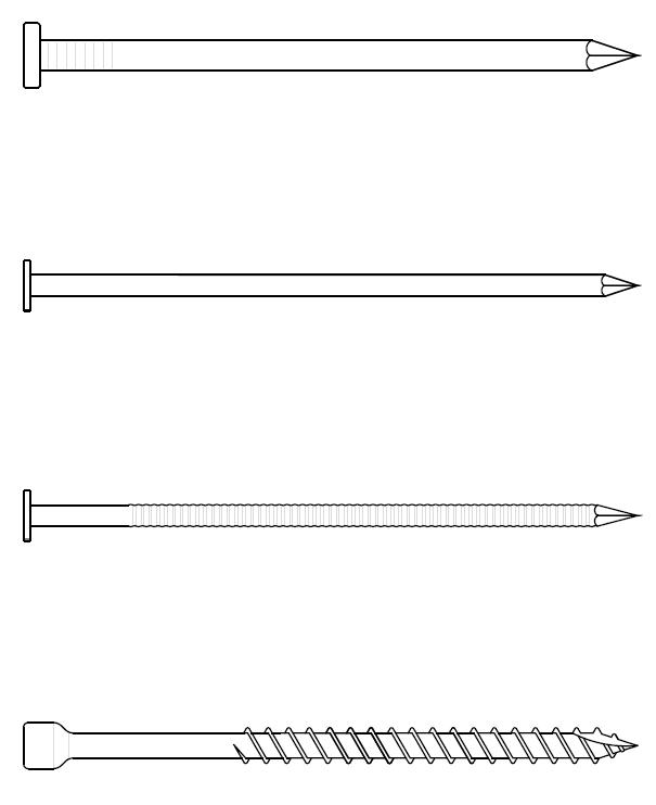
2-½” (64mm) MIN. RING-SHANK SIDING NAIL
This technical bulletin is a supplement to Section 4: Fastening Allura Products and Section 7: Allura Trim of the Allura Installation Manual dated October 2025. It is Cement Trim. Only those items specifically mentioned in this technical bulletin shall supersede the Installation Manual.
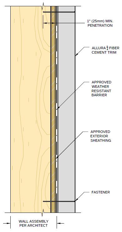
Fasteners shown are intended as an example of minimum dimensions. Additional fasteners may be used so long as they meet the minimum requirements outlined above and in the Allura Installation Manual.
2-¼” (64mm) MIN. TRIM SCREW
Trim Details
8/4 Fiber-Cement Trim
B01.A TECHNICAL BULLETIN
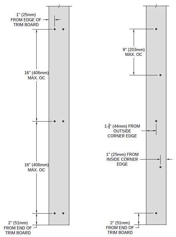
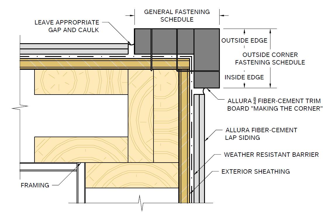
GENERAL FASTENING SCHEDULE
OUTSIDE CORNER FASTENING SCHEDULE
GENERAL FASTENING SCHEDULE
Applicable for 8/4X4 and 8/4X6 Allura Fiber-Cement Trim.
Position fasteners 1-inch (25mm) from side edge of trim board.
Position fasteners 2-inches (51mm) from end of trim board.
Space fasteners no more than 16-inches (406mm) apart on center.
OUTSIDE CORNER FASTENING SCHEDULE
To avoid driving the fastener into the adjacent trim, the trim board making the corner” or the board overlapping the adjacent board has a modified fastening schedule. Applicable for 8/4X4 and 8/4X6 Allura Fiber-Cement Trim.
Position fasteners 1-inch (25mm) from the inside corner edge of trim board.
Position fastener 1¾-inch (44mm) from the outside corner edge of trim board.
Position fasteners 2-inches (51mm) from end of trim board.
Space fasteners no more than 8-inches (203mm) apart on center alternating between the inside and outside corner.
ADDITIONAL INFORMATION
For additional resources, including our most current installation instructions and code reports, please visit our website at www.allurausa.com. For technical services email technical.services@elementia.com or call 844.4.ALLURA.