This Allura Backer Installation Guide provides general installation requirements for builders and contractors installing Allura Backer and Allura Backer with TrippleBlock on single-family residential and light commercial structures. Before starting any project with any product it is important to read this guide in its entirety.
This guide must be used in conjunction with project drawings and specifications, applicable building codes, and relevant compliance documents. The Allura installation requirements in this guide need to be reviewed by all parties responsible for installing Allura fiber-cement products. Failure to comply with Allura installation instructions and applicable building codes may affect product performance and void the product warranty. Allura will not accept any liability or responsibility under its written warranty for product failure caused by application that does not meet the requirements for proper installation.
All Allura technical documents, including this guide, are evaluated and revised periodically. To ensure the most current version is referenced when installing Allura fiber-cement products, please check the Allura website at www.allurausa.com. The reader is responsible for ensuring that they are using the most up-to-date information.
STORAGE & HANDLING
Keep Allura fiber-cement Backer clean and protected from direct exposure to the weather and elements. The material should be stored in its original packaging and in a covered area. They must be stored on a smooth, flat surface, not directly on the ground.
The product should always be carried by the narrow edge and evenly supported. Carrying Allura products flat causes excessive bending which can result in damage to the product. 4’X8’ backerboard should always be carried by two people.
SAFETY
Allura products contain respirable crystalline silica. Crystalline silica has been known to be a potential health danger for many years. This danger, however, can be mitigated with simple and effective precautions. The breathing in of small silica dust particles has been shown to cause lung cancer, silicosis, chronic obstructive pulmonary disease (COPD), and kidney disease. Silica dust is generated in Allura products when they are ground or cut. When used under normal conditions, Allura products are not considered cancerous or carry other health risk, although breathing excess amounts of respirable silica dust can be a cause of cancer or other diseases. Cigarette or cigar smoking can increase these risks. OSHA has published a guidance document (OSHA 3362-05 2009) pertaining to Controlling Silica Exposures During Construction (the “Guidance Document”).
Allura Backer Installation
Requirements, Guidelines & Best Practices
SAFETY (CONT.)
B07.A TECHNICAL BULLETIN
Additionally, OSHA has adopted a regulation pertaining to airborne silica (the “Silica Rule”). The Silica Rule dealing with respirable crystalline silica is found at 29 CFR §1926.1153.
Never dry-sweep dust or debris. Use a wet dust suppression method or HEPA vacuum for clean-up. To further limit respirable silica dust exposures, wear a properly fitted, NIOSH approved dust mask or respirator (e.g. N-95 dust mask) in accordance with applicable government regulations and manufacturer instructions.
DESCRIPTION & USE
Allura Backer is a single-faced, cellulose fiber-reinforced cement (fiber-cement) panels used as cementitious backer units for floor underlayment in the interior of buildings and backer boards for wall tile in tub and shower areas, and wall panels in shower areas. Allura Backer is evaluated in accordance with ASTM C1288 and is mold resistance per ASTM G21.
¼” Allura Backer
½” Allura Backer
FASTENERS
0.42-inch (10.7mm)
Weight per Piece Dimensions
0.25-inch (6.4mm) 28-lbs (12.7 kg) 60-lbs (27.2 kg)
3' x 5' (914mm x 1,524mm) 4' x 8' (1,219mm x 2,438mm)
3' x 5' (914mm x 1,524mm) 4' x 8' (1,219mm x 2,438mm)
40-lbs (18.1 kg)
85-lbs (38.6 kg)
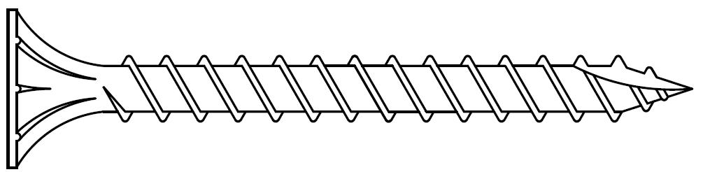
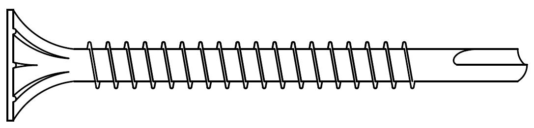
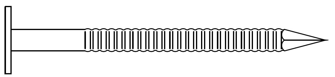
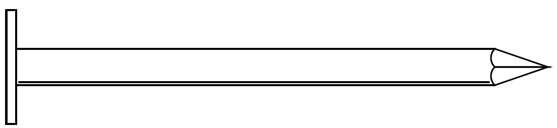
Fasteners must be corrosion-resistant, hot-dipped galvanized, or stainless steel. Allura is not responsible for the corrosion resistance of fasteners. Fasteners must be driven perpendicular and heads must be flush to the surface of the backer board. Do not over drive the fasteners. Keep fasteners a minimum of ⅜-inch (9.5mm) from the edge and 2-inches (51mm) from the corner.
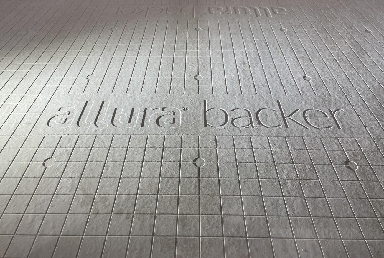
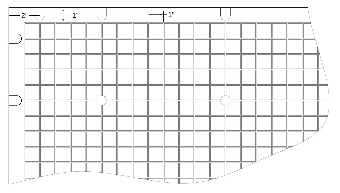
¼” Allura Backer comes with a helpful grid-patter debossed into the Backer. The grids are 1-inch (25mm) squares, with recessed nail points 8-inches (203mm) on center.
Note: Ceiling and overhead application requires a fastening pattern of 6-inches (152mm) on center.
CUTTING SCORE & SNAP
B07.A TECHNICAL BULLETIN
SHEARS
• Using a straight edge, such as a T-square, as a guide, score the face of the Backer using a carbide tipped scoring tool. While a carbide tipped scoring tool is recommended, a utility knife may be used as well.
• After scoring, snap the Backer upward against the straight edge.
• For small holes and cutouts, score around the perimeter and knock out from the face with a hammer.
Install Allura Backer with the debossed pattern or smooth face up. Follow all mortar and tile manufacturer’s written installation instructions, ANSI 108.4 and ANSI 108.5. Acrylic modified thin-set is recommended for setting of ceramic tiles. A minimum of 24-hours curing time shall be allowed before grouting or putting any weight on the installed tiles.
TAPE
• Use a 2” (50mm) wide, alkali-resistant, fiber-glass reinforcing tape.
Allura Backer Installation
Requirements, Guidelines & Best Practices
FLOOR INSTALLATION
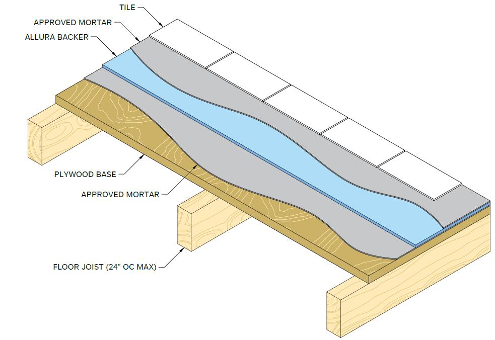
For all subfloors, use a minimum ⅝-inch (15.9mm) exterior grade plywood or ²³⁄₃₂ -inch (18.3mm) OSB with an exposure 1 classification or better that complies with all local building codes and ANSI 108.11. The floor must be engineered not to exceed the L/360 deflection criteria, (L/720 for natural stone) including live and dead design loads, for the specific joist spacing used. Supporting joists must be spaced a maximum of 24-inch (610mm) on center.
Ensure the subfloor is structurally sound and in good condition. Replace any damaged or uneven sections to ensure the subfloor is flat before installing Allura Backer.
Allura recommends ¼” Backer for floor applications, unless ½” Backer is necessary for transitions.
LAY-OUT & CUTTING
• Ensure the subfloor is sound, clean, and flat prior to installation.
TAPING & FINISHING
• Ensure the Backer is clean and free of any dirt, dust, debris or deleterious material on the surface and between the backer boards prior to beginning.
• Stagger joints to ensure backer board joints DO NOT align with subfloor joints. NEVER have all four corners of the backer board meet at a single point.
• Allow for a ⅛-inch (3.2mm) gap between board edges, walls, cabinet bases, etc.
• Score and snap, or cut Allura Backer to the required sizes. Make all necessary cut-outs and notch-outs.
ATTACHMENT
• Apply a supporting bed of modified thin-set to the subfloor per the manufacturer’s instructions using a ¼” notched trowel.
• Embed the Allura Backer evenly and firmly into the wet mortar.
• Fasten Allura Backer 8-inch (203mm) on center over the entire surface using a minimum 1-¼” (31.8mm) long fastener. If using ½” Backer use a minimum 1-½” (38.1mm) long fastener.
• Prior to finishing, fill all joints with mortar.
• Embed a 2” (50mm) wide, alkali-resistant, fiber-glass tape into the mortar and level.
• Wipe the surface with a wet sponge or mop immediately prior to installing the mortar. The Backer should be damp, but without standing water. Work in sections to ensure the Backer remains damp immediately prior to installing mortar.
• Refer to the manufacturer’s published application guides and industry standards for complete finishing instructions.
Allura Backer Installation
Requirements, Guidelines & Best Practices
WALL INSTALLATION
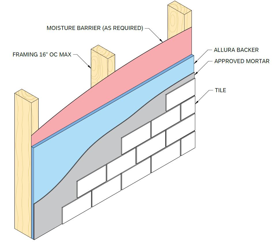
For all walls, use minimum 2” x 4” SPF (0.42 SG) wood or 20-gauge metal studs spaced a maximum of 16-inches (406mm) on center. Ensure the framing is straight, evenly aligned and properly spaced. Framing must comply with all local building codes and ANSI A108.11. All corner framing in tub and shower enclosures must be braced.
In wet areas, a moisture barrier must be used where required by building code. If required, install a code compliant moisture barrier following the manufacturer’s installation instructions.
Allura recommends using ½” Backer for wall installations. If using ¼” Backer, install additional blocking perpendicular to the framing to ensure all edges of the ¼” Backer are supported.
LAY-OUT & CUTTING
• Allura Backer may be installed vertically or horizontally.
• Ensure all edges parallel to framing are supported by a structural framing (stud).
• Stagger joints to ensure all four corners of the backer board NEVER meet at a single point.
• Allow for a ⅛-inch (3.2mm) gap between board edges, walls, cabinet bases, etc.
• Allow for a ¼-inch (6.4mm) gap between the backer and floors and tub or shower pans. Caulk the gap accordingly.
• When abutting to ½” drywall, use Allura ½” Backer. Alternately, Allura ¼” Backer may be shimmed with furring secured to each stud.
• Score and snap, or cut Allura Backer to the required sizes. Make all necessary cut-outs and notch-outs.
• Expansion joints shall be used at all inside and outside corners, as well as every 12-feet (3.6m) of wall.
ATTACHMENT
• Fasten Allura Backer 8-inches (203mm) on center to structural members (studs and blocking) using a minimum 1-¼” (31.8mm) long fastener. If using ½” Backer use a minimum 1-½” (38.1mm) long fastener.
TAPING & FINISHING
• Ensure the Backer is clean and free of any dirt, dust, debris or deleterious material on the surface and between the backer boards prior to beginning.
• Prior to finishing, fill all joints with mortar.
• Embed a 2” (50mm) wide, alkali-resistant, fiber-glass tape into the mortar and level.
• Wipe the surface with a wet sponge or mop immediately prior to installing the mortar. The Backer should be damp, but without standing water. Work in sections to ensure the Backer remains damp immediately prior to installing mortar.
• Refer to the manufacturer’s published application guides and industry standards for complete finishing instructions.
Allura Backer Installation
Requirements, Guidelines & Best Practices
CEILING INSTALLATION
B07.A TECHNICAL BULLETIN
For all ceilings, use minimum 2” x 4” SPF (0.42 SG) wood framing or minimum 20-gauge metal studs spaced a maximum of 16-inches (406mm) on center. Ensure the framing is straight, evenly aligned and properly spaced. Framing must comply with all local building codes and ANSI A108.11. All corner framing in tub and shower enclosures must be braced.
In wet areas, a moisture barrier must be used where required by building code. If required, install a code compliant moisture barrier following the manufacturer’s installation instructions.
LAY-OUT & CUTTING
• Install boards with the long edges perpendicular to the joists and the short edges centered on the joints.
• Stagger joints to ensure all four corners of the backer board NEVER meet at a single point.
• Allow for a ⅛-inch (3.2mm) gap between board edges, walls, etc.
• When abutting to ½” (12.8mm) drywall, use Allura ¼” Backer shimmed with furring secured to each stud.
• Score and snap, or cut Allura Backer to the required sizes. Make all necessary cut-outs and notch-outs.
ATTACHMENT
• Fasten Allura Backer 6-inches (152mm) on center to structural members (joists). Allura recommends using screws when fastening overhead.
• Fasteners must provide a minimum 1-inch (25mm) thread engagement into wood framing and a minimum ¼-inches (6.4mm) or three full thread engagement into metal framing.
FRAMING SCREW MIN. LENGTH
WOOD № 8 Ribbed Wafer-Head 1-⅝” (41.3mm)
№ 8 Self-Tapping Ribbed Wafer-Head 1-¼” (31.8mm)
TAPING & FINISHING
• Ensure the Backer is clean and free of any dirt, dust, debris or deleterious material on the surface and between the backer boards prior to beginning.
• Prior to finishing, fill all joints with mortar.
• Embed a 2” (50mm) wide, alkali-resistant, fiber-glass tape into the mortar and level.
• Wipe the surface with a wet sponge or mop immediately prior to installing the mortar. The Backer should be damp, but without standing water. Work in sections to ensure the Backer remains damp immediately prior to installing mortar.
• Refer to the manufacturer’s published application guides and industry standards for complete finishing instructions
Allura Backer Installation
Requirements, Guidelines & Best Practices
COUNTER INSTALLATION
B07.A TECHNICAL BULLETIN
For all countertops, cabinets should be set and level with a minimum ½” (12.7mm) exterior-grade plywood attached and supported across the top of the cabinet. Supports must be spaced a maximum of 16-inches (406mm) on center.
LAY-OUT & CUTTING
• Ensure the substrate is sound, clean, and flat prior to installation.
• Stagger joints to ensure backer board joints DO NOT align with subfloor joints. NEVER have all four corners of the backer board meet at a single point.
• Allow for a ⅛-inch (3.2mm) gap between board edges, walls, cabinet bases, etc.
• Score and snap, or cut Allura Backer to the required sizes. Make all necessary cut-outs and notch-outs.
ATTACHMENT
• Apply a supporting bed of modified thin-set to the plywood cabinet top per the manufacturer’s instructions using a ¼” notched trowel.
• Embed the Allura Backer evenly and firmly into the wet mortar.
• Fasten Allura Backer 8-inches (203mm) on center over the entire surface using a minimum ¾” (19mm) long fastener. If using ½” Backer use a minimum 1” (25mm) long fastener. 18 gauge corrosion-resistant ¾” (19mm) staples with a ¼” (6.4mm) crown may also be used for countertops.
TAPING & FINISHING
• Ensure the Backer is clean and free of any dirt, dust, debris or deleterious material on the surface and between the backer boards prior to beginning.
• Prior to finishing, fill all joints with mortar.
• Embed a 2” (51mm) wide, alkali-resistant, fiber-glass tape into the mortar and level.
• Wipe the surface with a wet sponge or mop immediately prior to installing the mortar. The Backer should be damp, but without standing water. Work in sections to ensure the Backer remains damp immediately prior to installing mortar.
• Refer to the manufacturer’s published application guides and industry standards for complete finishing instructions.
PERFORMANCE CHARACTERISTICS & CERTIFICATIONS
• Allura Backer complies with ASTM C1288. Consult QAI CERus-1052 for additional information.
• Allura Backer has a flame spread index of 0 and a smoke developed index of 5 when tested and evaluated in accordance with ASTM E84.
• Allura Backer is mold resistant when tested and evaluated in accordance with ASTM G21.
WARRANTY
20-Year Transferable Limited Product Warranty. Go to www.allurausa.com/warranties for more information.
ADDITIONAL INFORMATION
For additional resources, including our most current installation instructions and code reports, please visit our website at www.allurausa.com. For technical services email technical.services@elementia.com or call 844.4.ALLURA