B11.A TECHNICAL BULLETIN

This technical bulletin is intended to be read in conjunction with the Allura Installation Manual dated October 2025 and the QAI CERus-1012 expiration November 2028. If a more current version of the Installation Manual, The QAI Code Report, or this technical bulletin is available, this version is no long applicable.
Assembly Design
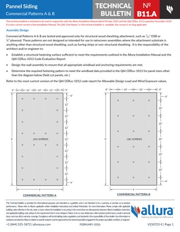
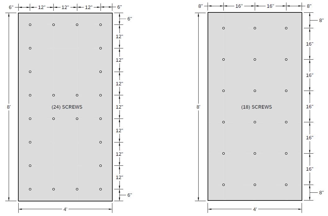
Commercial Patterns A & B are tested and approved only for structural wood sheathing attachment, such as ⁷⁄₁₆” OSB or ½” plywood. These patterns are not designed or intended for use in rainscreen assemblies where the attachment substrate is anything other than structural wood sheathing, such as furring strips or non-structural sheathing. It is the responsibility of the architect and/or engineer to:
• Establish a structural fastening surface sufficient to meet the requirements outlined in the Allura Installation Manual and the QAI CERus-1012 Code Evaluation Report.
• Design the wall assembly to ensure that all appropriate windload and anchoring requirements are met.
• Determine the required fastening pattern to meet the windload data provided in the QAI CERus-1012 for panel sizes other than the diagram below (field cut panels, etc.)
Refer to the most current version of the QAI CERus-1012 code report for Allowable Design Load and Wind Exposure values.

Pannel Siding
Commercial Patterns A & B
ATTACHMENT
B11.A TECHNICAL BULLETIN
When attaching the panel to the structural wood sheathing DO NOT “tack-nail” or use fasteners placed outside of the Commercial Pattern to temporarily hold the panel. It is recommended the fastener pattern be pre-marked on the panel prior to hanging. The installer may also pre-drill some or all of the fastener locations to make fastening quicker and easier.
Tip: If using a chalk line to mark panels for the fastener pattern ensure the chalk can be removed. Some chalk is considered permanent and may bleed through lighter colored paints. DO NOT use chalk on Spectrum® pre-finish or Spectrum The Wood Series

Install fasteners working from one edge to the opposite edge (typically from top to bottom). DO NOT fasten from both edges towards the middle. This can create stress on the fiber-cement panel siding.
Note: Commercial Patterns A & B are NOT intended to fasten 16-inch (406mm) wide panels.
SFS TW-S-D12
The SFS fastener TW-S-D12-4.8x38 is specifically referenced as the fastener for Panel Siding installation using Commercial Patterns A & B in the QAI CERus-1012 Code Evaluation Report. For panel sizes outside of full 4’X8’ sheets, consult the architect’s or engineer’s determination on fastening pattern.
Fastener Length Thread Length Diameter Dome Head
ARCHITECTURAL REVEALS (EXTRUDED ALUMINUM TRIM)
Allura fiber-cement vertical panel siding may be used in conjunction with extruded aluminum trim, enabling architects to execute unique exterior wall designs that blend contemporary aesthetics with fiber-cement’s significant long-term performance and sustainability. When using architectural reveals DO NOT caulk between the aluminum trim and the fiber-cement siding. Panel edges shall be an unmodified factory finished edge or a sealed edge. Cut edges of the fiber-cement shall be primed or painted.
When using reveal systems, cladding system design becomes a prescriptive approach based on many factors including wall system construction, and fastening requirements for the siding depend on the specific wall system design. When incorporating Allura fiber-cement siding into a reveal cladding system, adhere to the recommendations and requirements contained in this document, the latest version of the Allura Installation Manual, the installation instructions provided by the trim reveal system manufacturer, as well as all national, state, and local building codes. Allura will not accept any liability or responsibility for cladding system design or for any product failure caused by application that does not meet the requirements for proper installation.
ADDITIONAL INFORMATION
Always refer to the most current version of the Allura Installation Manual and relevant jurisdictional Evaluation Report for fastener specifications and assembly design. For additional resources, including our most current installation instructions and code reports, please visit our website at www.allurausa.com. For technical services email technical.services@elementia.com or call 844.4.ALLURA.
For more information on the SFS TW-S-D12 go to us.sfs.com