Code Evaluation Report Allura Fiber Cement - CERus - 1012
REPORT HOLDER: Plycem USA, LLC
CONTACT DETAILS: 396 W. Greens Road, Suite 300 Houston, TX 77067 USA www.allurausa.com
CSI DIVISION: 07 00 00 - Thermal and Moisture Protection
CSI SECTION: 07 46 46 – Fiber-Cement Siding
APPLICABLE CODES: 2024, 2021, 2018, 2015 International Building Code (IBC) 2024, 2021 2018, 2015 International Residential Code (IRC) 2023 Florida Building Code (FBC) 2023 Florida Residential Code (FRC) 2022 California Green Building Standards Code (CALGreen), Title 24 Part 11 2020, 2015 ICC 700 National Green Building Standard™ (ICC 700)
Exterior Cladding and Interior Wall and Ceiling Finish (Dry Room).
• Exterior cladding on bearing and non-load bearing exterior walls.
• Interior walls and ceilings
Allura® and TerraPlank™ products are Type A Grade II fiber-cement products complying with Section 1403.9 of the 2024 IBC, Section 1403 10 of the 2021 / 2018 IBC and Section 1404.10 of the 2015 IBC as well as 2024 / 2021 / 2018 / 2015 IRC Section R703.10 for use as exterior siding. Allura® and TerraPlank™ are available in various shapes and sizes as outlined in Table 1 of this report. Allura® and TerraPlank™ fiber-cement are available in a wide variety of color and texture options applied over the fiber-cement product.
When used in exterior cladding applications Allura® and TerraPlank™ fiber-cement are intended for installation over structural sheathing materials listed in Section 2304.6 of the 2024 / 2021 / 2018 / 2015 IBC or Section R604 of the 2024 / 2021 / 2018 / 2015 IRC or non-structural sheathing as outlined in 2024 / 2021 / 2018 / 2015 IRC Section R703.15.1. Installation shall include a water-resistive barrier complying with Section 1402.2 of the 2024 / 2021 / 2018 IBC and Section 1403.2 of the 2015 IBC or R703.2 of the 2024 / 2021 / 2018 / 2015 IRC as appropriate.
Allura® and TerraPlank™ fiber-cement products have a flame spread index of 0 and a smoke developed index of ≤ 5 when evaluated in accordance with ASTM E84.
Allura® and TerraPlank™ fiber-cement products are classified non-combustible and comply for use in Types I-V construction, including use in fire-resistance rated applications. See sections 4.3 and 4.4 of this report respectively for details.
Allura® and TerraPlank™ fiber-cement products are available in Allura® and TerraPlank™ Lap Siding, Allura® and TerraPlank™ Panel, Allura® and TerraPlank™ Shake, and Allura® Shake Select designations in dimensions as outlined in Table 1 of this report.
1. Noted products are available in vented and non-vented options.
Allura® and TerraPlank™ fiber-cement cladding products comply with the 2023 FBC Section 1404.10 and 2023 FRC Section 703.10 fiber-cement siding conforming to ASTM C1186 as Type A Grade II fiber cement excluding use in areas defined as high-velocity hurricane zones (HVHZ) applications. See Section 10 of this report for additional details.
Allura® fiber-cement products with Spectrum, comply with the 2022 CALGreen and 2020 ICC 700 as prefinished materials, requiring no additional site-applied finishings. See Section 10 of this report for further details.
CODE EVALUATION REPORT
3.0
DESIGN:
Allura® and TerraPlank™ fiber-cement are exterior cladding products for installation over code complying wall framing, and sheathing including an approved water-resistive barrier. Use of Allura® or TerraPlank™ does not require professional design but shall be in applications where wind-resistance requirements determined in accordance with the applicable code are within the limits as outlined in Section 8.1 of this report for installations described.
4.0 INSTALLATIONS:
4.1
General:
Installation of Allura® and TerraPlank™ fiber-cement products must comply with the manufacturer’s published installation instructions, this report, and the applicable code(s). Where differences are found between documents, this report and the applicable building code shall be followed.
Installation of Allura® and TerraPlank™ fiber-cement products shall be over exterior walls including the code prescribed water-resistive barrier and sheathing products in accordance with Sections 1404.1 through 1404.4 of the 2024 / 2021 / 2018 IBC, Section 1404.17 of the 2024 IBC, Section 1404.16 of the 2021 / 2018 IBC, Sections 1405.1 through 1405.3 and Sections 1404.10 of the 2015 IBC, and Sections R703.1 and R703.3 of the 2024 / 2021 / 2018 / 2015 IRC. Allura® and TerraPlank™ fiber-cement Lap Siding and Panel products can be installed over sheathing of structural or non-structural designation, where the wall is constructed in accordance with the applicable code. Allura® fiber-cement Shake Select products require installation over a min. ⁷⁄₁₆-inch (11 mm) thickness oriented strandboard (OSB) or ½inch (13 mm) thickness plywood Exposure 1 classification wood sheathing types. Fasteners for attachment of Allura® and TerraPlank™ fiber-cement products must be corrosion-resistance, hot-dipped galvanized, or stainless steel. Clearance between Allura® and TerraPlank™ fiber-cement siding products and earth on the exterior of a building shall be ≥ 6-inches (152 mm). Clearance between Allura® and TerraPlank™ fiber-cement siding products and horizontal concrete slabs or similar surfaces exposed to weather shall be ≥ 1-inch (25 mm) unless under a sheltered hardscape.
Where field cuts are required, all field-cut edges are to be painted or sealed Paint is not required to be applied to the backside of Allura® and TerraPlank™ fiber-cement products.
Installation of Allura® and TerraPlank™ fiber-cement assemblies shall conform to Tables 2-5 and Figures 3-9 of this report for the respecitve product type.
4.1.1
Special Inspection:
2024 / 2021 IBC Section 1705.12: Special inspection including periodic special inspection for wind resistance are required for buildings constructed in the following areas:
1. Wind Exposure Category B, where V is ≥ 150 mph (241 km/hr).
2. Wind Exposure Category C or D, where V is ≥ 140 mph (225 km/hr).
Special inspection is to confirm installation is in conformance with Section 8.1 of this report. Installation in areas of maximum V(basic design wind speed) of 130 mph (209 km/hr), maximum mean roof height of 40 ft (12.2 m) and Exposure Category B do not require special inspection.
4.2 New Construction:
4.2.1
CODE EVALUATION REPORT
Allura® and TerraPlank™ Lap Siding
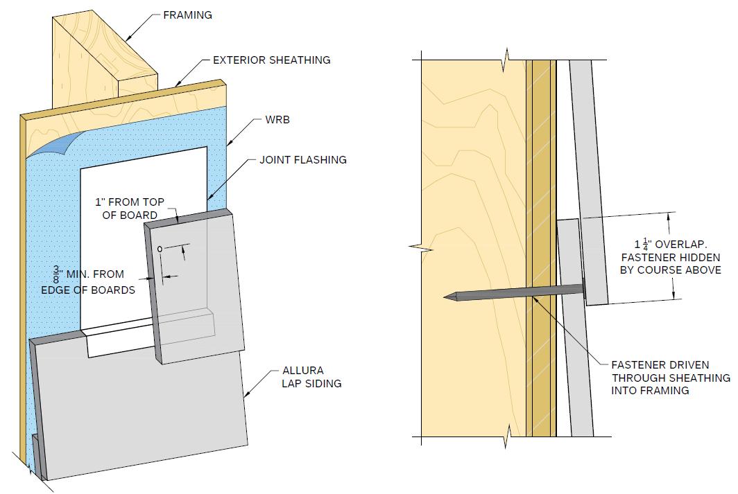
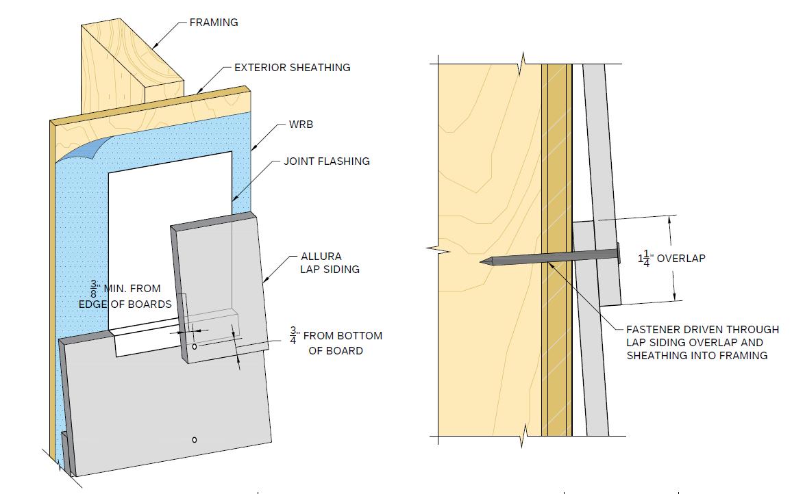
Allura® and TerraPlank™ Lap Siding can be installed in a face or blind fastened assembly, as detailed in Section 9.1 of this report and in accordance with Table 2 of this report. Installation is restricted to horizontal orientation.
Vertical joints between boards must occur over studs, unless otherwise noted in Table 2 of this report. Maintain a min. ⅛-inch (3.2mm) clearance when siding meets a vertical termination, such as windows, doors, trim, corners, and penetrations. Caulk all vertical terminations or transitions unless siding terminates into a pocket or “J” channel receiver. Maintain a ¼-inch (6.4 mm) clearance when Allura® or TerraPlank™ Lap Siding meets horizontal flashing, such as window and door heads, band boards, water tables etc. Caulking is not to be applied between the siding and the horizontal flashing.
See Section 9.1 for details of Allura® and TerraPlank™ Lap Siding installation.
4.2.2 Allura® TerraPlank™ Panel Siding
Allura® and TerraPlank™ Panel are installed in an exposed fastener (face fastened) application and in accordance with Table 3 of this report. Installation can be in vertical or horizontal orientation (16-inch / 406 mm width panels are intended for vertical installation only) where panels horizontal and vertical joints are treated as outlined below.
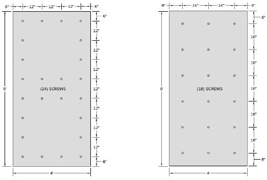
All edges of Allura® and TerraPlank™ Panels shall be backed by framing or solid blocking for attachment unless otherwise noted in Table 3 of this report. Fasteners are to be installed a min. 2-inches (51 mm) from panel corners in each direction with a min. ⅜-inch (9 mm) edge distance. Vertical edges shall be lightly butted and centered on framing members (unless otherwise noted in Table 3) and sealed with caulking, covered with a battens, or designed to meet 2024/2021/2018 IBC Section 1404.2, 2015 IBC Section 1403.2 and IRC Section R703.1 Horizontal joints are to include “Z” flashing, between panels leaving a ¼-inch (6 mm) gap. Maintain a min. ⅛-inch (3 mm) clearance when siding meets a vertical termination, such as windows, doors, trim, corners, penetrations, etc. Caulk all vertical terminations or transitions unless siding terminates into a pocket or “J” channel receiver. Maintain a ¼-inch (6 mm) clearance when Allura® or TerraPlank™ Panel meets horizontal flashing, such as window and door heads, band boards, water tables etc. Caulking is not to be applied between the siding and the horizontal flashing.
4.2.3 Allura® and TerraPlank™ Shake Siding and Allura® Shake Select Siding
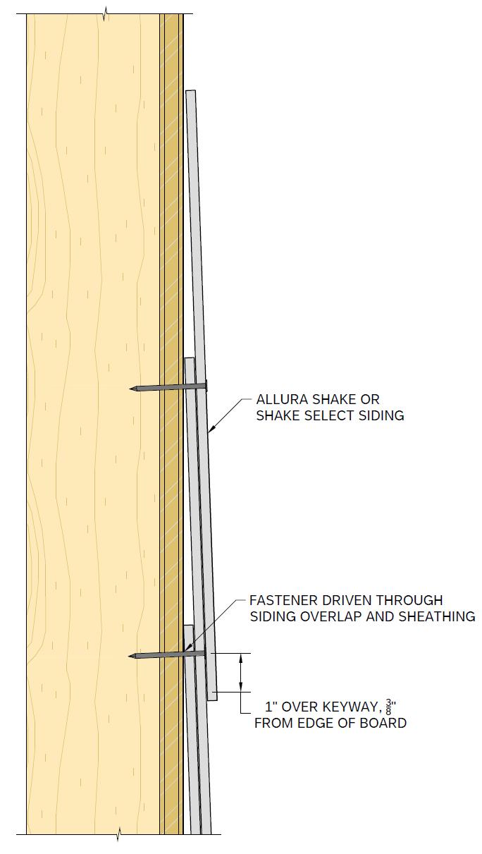
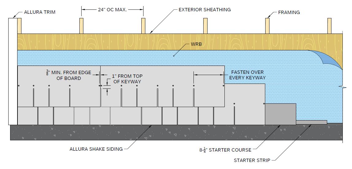
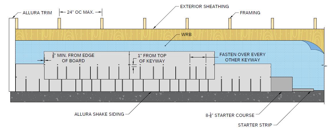
Allura® and TerraPlank™ Shake Siding and Allura® Shake Select Siding are installed in a hidden fastener (blind nailed) application as detailed in Section 9.3 of this report and in accordance with Table 4 and 5 of this report.
Maintain a min. ⅛-inch (3.2mm) clearance when siding meets a vertical termination, such as windows, doors, trim, corners, penetrations, etc. Caulk all vertical terminations or transitions unless siding terminates into a pocket or “J” channel receiver. Maintain a ¼-inch (6.4mm) clearance when Allura® or TerraPlank™ Shake Siding or Allura® Shake Select Siding meets horizontal flashing, such as window and door heads, band boards, water tables etc. Caulking is not to be applied between the siding and the horizontal flashing.
See Section 9.3 for details of Allura® and TerraPlank™ Shake and Allura® Shake Select installation.
CODE EVALUATION REPORT
4.3 Fire-Resistance Rated Construction
Allura® and TerraPlank™ exterior claddings, as detailed, are approved for use where a limited (restricted) load-bearing fire-resistance rated construction is required for up to 1-hour, with the fireresistance rating applied for interior or exterior of wall fire exposure. Assembly details can be found in Section 8.2 and Table 6 of this report.
4.4 Types I-IV Construction
Allura® and TerraPlank™ exterior claddings are classified non-combustible and can be used as exterior cladding in Types I-IV construction when installed in accordance with this report with the following limitations:
4.4.1 Any Combustible Water-Resistive Barriers
Allura® and TerraPlank™ fiber-cement exterior cladding is approved for use as exterior cladding in Types I-IV construction when installed with a combustible water-resistive barrier where the building is limited to ≤ 40 ft (12.2 m) measured from grade.
Where Allura® or TerraPlank™ fiber-cement products are used on exterior walls of Types I-IV construction > 40 ft (12.2 m) height above grade with combustible water-resistive barriers, the intended exterior wall assembly shall be listed by an approved agency as complying with the requirements of NFPA 285. The listed assembly is to outline approval for use of noncombustible fiber-cement products complying as Grade II Type A per ASTM C1186 of min. ⁵⁄₁₆inch (8 mm) thickness. Allura® and TerraPlank™ installation shall be in accordance with the approved agency’s listing installation requirements for siding type and Table 6 of this report.
Allura® and TerraPlank™ fiber-cement exterior cladding is approved for use as exterior cladding in Types I-IV construction when installed with a combustible water resistive barrier in buildings > 40 ft (12.2 m) height where the water resistive barrier is the only combustible component meeting the following criteria:
1. The water-resistive barrier has a flame spread of ≤ 25 and smoke developed index of ≤ 450 when evaluated in accordance with ASTM E84 or UL 723, and
2. The water-resistive barrier meets the following criteria when evaluated to ASTM E1354 at the intended installed thickness tested in the horizontal orientation with an applied heat flux of 50 kW/m2:
a. Peak heat release rate of ≤ 150 kW/m2
b. Total heat release of ≤ 20 MJ/m2
c. Effective heat of combustion of ≤ 17 MJ/kg
5.0 LIMITATIONS
CODE EVALUATION REPORT
• Allura® and TerraPlank™ fiber-cement products are to be installed in accordance with the manufacturer’s installation instructions, the applicable code and this report. Where differences exist between documents, the applicable code and this report shall be followed.
• Where Allura® and TerraPlank™ fiber-cement products are used in fire-resistance rated construction, installation is to be in accordance with Sections 4.3 of this report, with load restricted to 35% of Load Resistance Factor Design (LRFD) design load determined per the National Design Specification for Wood Construction (NDS). Where Allura® and TerraPlank™ fiber-cement products are used in Types I-IV construction, installation is to be in accordance with Section 4 of this report and the applicable code.
• Allura® and TerraPlank™ fiber-cement products require installation with corrosion-resistant fasteners, use of electro-galvanized corrosion treatment type is not recommended.
• Allura® and TerraPlank™ fiber-cement products are evaluated for use as exterior cladding and interior finish (dry room) applications. Use of Allura™ fiber-cement products in alternate applications is outside the scope of this report.
• Allura® and TerraPlank™ fiber-cement products are manufactured in White City, OR, Roaring River, NC, Bogota, Colombia, Cali, Colombia, Santa Clara, Mexico and Nuevo Laredo, Mexico with inspections by QAI Laboratories.
6.0 SUPPORTING INFORMATION:
The following data has been submitted for evaluation of Allura® and TerraPlank™ fiber-cement products:
o Data outlining compliance for surface burning characteristics evaluated to ASTM E84.
o Data outlining compliance with ASTM C1186 as Grade II Type A fiber-cement material.
o Data evaluating Allura™ assemblies for transverse load resistance in accordance with ASTM E330.
o Data evaluating wind speed resistance in accordance with ASCE 7-22
o Data evaluating fire-resistance in accordance with ASTM E119.
o Data evaluating non-combustibility in accordance with ASTM E136.
CODE EVALUATION REPORT
7.0 MARKING:
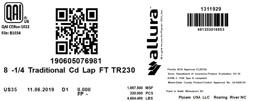
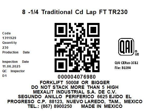
Examples of Alllura™ fiber-cement panels finished product labels are outlined in Figures 1 and 2 below.
TerraPlank™ labeling is consistent with labeling for Allura® fiber-cement products shown in Figures 1 and 2.
Figure 1 – Allura® Finished Product Label Including CERUS-1012 and QAI Certification Mark (USA)
Figure 2 – Allura® Finished Product Label Including CERUS-1012 and QAI Certification Mark (Mexico)
1
3
4 Face 9-¼
6 Blind 9-¼
CODE EVALUATION REPORT
8 Face ≤ 8-¼ 6d collated siding nail, min. 2'’ (51 mm) length 12'' (305 mm) into sheathing and studs Dimensional
9 Face ≤ 8-¼ 6d collated siding nail, min. 2'’ (51 mm) length 8'' (203 mm) into sheathing and studs
Dimensional lumber framing including min.
(11 mm)
8-¼ No. 8 self-tapping
(305 mm) into furring strips
furring strips at 8'' (203 mm) vertical spacing, anchored into underlying sheathing
Blind 5-¼ 11-gauge smooth shank roofing nail of 1-¾” (45 mm) length 16'' (406 mm) into each stud
1. Installation must be in accordance with the manufacturer's installation instructions.
2. For blind fastening method refer to Figure 3 For face fastening method refer to Figure 4
3. Fasteners used must be corrosion resistant.
4. Unless otherwise noted, wood framing/furring species must have a specific gravity of 0.42 or greater. Furring attachment to structural wood sheathing and wood and steel framing must be determined by the project design engineer to resist the maximum wind speeds.
9. Building height is the mean roof height (ft) of a building, except that eave height shall be used for roof angle less than or equal to 10º (2-12 roof slope)
10. Where non-structural sheathing types are included, increase the length of fasteners by the sheathing thickness to maintain min. fastener penetration into framing.
11. Wind speed values have been determined in accordance with ASCE 7-22.
12. Framing anchoring, and attachment of sheathing to underlying framing is to be in accordance with the applicable code and sufficient to resist service loads.
13. Unless otherwise specified, steel studs are to be minimum 33 ksi yield, G60 galvanized in accordance with the applicable code.
14. Allowable design pressures are determined for worst case negative pressure loading. Where no sheathing is installed, allowable positive pressures are limited to equivalent negative pressures noted.
15. Fastener length can be adjusted to penetrate underlying steel framing a minimum 1/4-inch or three (3) full treads.
(152 mm) around perimeter, 12'' (305 mm) in the field into framing
Table 3 – Allura® and TerraPlank™ Panel Siding Installations, Wind Speeds and Design Pressures1
32 Face 48
No. 8 self-tapping wafer-head
screws, min. 1-⅝” (41 mm) length 6'' (152 mm) around perimeter, 12'' (305 mm) in the field into framing13
33 Face 48 No. 8 self-tapping wafer-head screws, min. 1-⅝” (41 mm) length 6" (152mm)
34 Face 48 No. 8 self-tapping wafer-head
min. 1-⅝” (41 mm) length 6'' (152 mm) around perimeter, 12'' (305 mm) in the field into framing13,16
35 Face 48 SFS TW-S-D12
screws, min. 1-½” (38 mm) length
Commercial Pattern "A" into sheathing2,16
36 Face 48 SFS TW-S-D12
screws, min. 1-½” (38 mm) length Manufacturer's Commercial Pattern "B"
37 Face 48
lumber framing including min. ⁷⁄₁₆'' (11 mm) structural wood sheathing
Aerosmith VersaPin LH 2635SBG pin min. 2-½” (64 mm) length 8" (203 mm) vertically and horizontally into sheathing16 Dimensional lumber with 1'' (25 mm) Owens
38 Face 48 No. 8 wafer-head screws, min. 1-⅝” (41 mm) length 6" (152 mm) vertically, and 16'' (405 mm) horizontally into sheathing
Structural Insulated Sheathing (SIS)
Dimensional lumber framing including min. ⁷⁄₁₆'' (11 mm) structural wood sheathing
39 Face 48
No. 8 self-tapping wafer-head screws, min. 1-⅝” (41 mm) length
8" (203 mm) vertically and 16'' (406 mm) horizontally into furring
Dimensional lumber framing including min. ⁷⁄₁₆ “ (11 mm) structural wood sheathing with 1x3 pressure treated furring strips at 16'' (406 mm) horizontally
1. Installation must be in accordance with the manufacturer's installation instructions.
2. For Commercial Pattern A see Figure 5. For Commercial Pattern B see Figure 6.
3. Fasteners used must be corrosion resistant.
4. Unless otherwise noted, wood framing/furring species must have a specific gravity of 0.42 or greater. Furring attachment to structural wood sheathing and wood and steel framing must be determined by the project design engineer to resist the maximum wind speeds.
9. Building height is the mean roof height (ft) of a building, except that eave height shall be used for roof angle less than or equal to 10º (2-12 roof slope)
10. Where non-structural sheathing types are included, increase the length of fasteners by the sheathing thickness to maintain min. fastener penetration into framing.
11. Wind speed values have been determined in accordance with ASCE 7-22.
12. Framing anchoring, and attachment of sheathing to underlying framing is to be in accordance with the applicable code and sufficient to resist service loads.
13. Unless otherwise specified, steel studs are to be minimum 33 ksi yield, G60 galvanized in accordance with the applicable code
14. Allowable design pressures are determined for worst case negative pressure loading. Where no sheathing is installed, allowable positive pressures are limited to equivalent negative pressures noted.
15. Fastener length can be adjusted to penetrate underlying steel framing a minimum 1/4-inch or three (3) full treads. 16. Assembly is not intended for use with 16-inch (406 mm) width panel siding.
40 Blind 48'' Shake 6d collated ring shank siding nail, min. 2'' (51 mm) length One fastener at every keyway into sheathing
1. Installation must be in accordance with the manufacturer's installation instructions.
2. See Figures 7 and 8.
3. Fasteners used must be corrosion resistant.
4. Unless otherwise noted, wood framing/furring species must have a specific gravity of 0.42 or greater. Furring attachment to structural wood sheathing and wood and steel framing must be determined by the project design engineer to resist the maximum wind speeds.
9. Building height is the mean roof height (ft) of a building, except that eave height shall be used for roof angle less than or equal to 10º (2-12 roof slope)
10. Where non-structural sheathing types are included, increase the length of fasteners by the sheathing thickness to maintain min. fastener penetration into framing.
11. Wind speed values have been determined in accordance with ASCE 7-22.
12. Framing anchoring, and attachment of sheathing to underlying framing is to be in accordance with the applicable code and sufficient to resist service loads.
13. Unless otherwise specified, steel studs are to be minimum 33 ksi yield, G60 galvanized in accordance with the applicable code
14. Allowable design pressures are determined for worst case negative pressure loading. Where no sheathing is installed, allowable positive pressures are limited to equivalent negative pressures noted.
15. Fastener length can be adjusted to penetrate underlying steel framing a minimum 1/4-inch or three (3) full treads.
Fastener installed at edge of panel and every other (every second) keyway through sheathing per Figure 9
Fastener installed at edge of panel and every other (every second) keyway through sheathing per Figure 9
Fastener installed at edge of panel and every other (every second) keyway through sheathing per Figure 1915
1. Installation must be in accordance with the manufacturer's installation instructions.
2. See Figures 7 & 9
3. Fasteners used must be corrosion resistant.
4. Unless otherwise noted, wood framing/furring species must have a specific gravity of 0.42 or greater. Furring attachment to structural wood sheathing and wood and steel framing must be determined by the project design engineer to resist the maximum wind speeds.
9. Building height is the mean roof height (ft) of a building, except that eave height shall be used for roof angle less than or equal to 10º (2-12 roof slope)
10. Where non-structural sheathing types are included, increase the length of fasteners by the sheathing thickness to maintain min. fastener penetration into framing.
11. Wind speed values have been determined in accordance with ASCE 7-22.
12. Framing anchoring, and attachment of sheathing to underlying framing is to be in accordance with the applicable code and sufficient to resist service loads.
13. Unless otherwise specified, steel studs are to be minimum 33 ksi yield, G60 galvanized in accordance with the applicable code
14. Allowable design pressures are determined for worst case negative pressure loading. Where no sheathing is installed, allowable positive pressures are limited to equivalent negative pressures noted.
15. Fastener length can be adjusted to penetrate underlying steel framing a minimum 1/4-inch or three (3) full treads.
CODE EVALUATION REPORT
8.2 Fire-Resistance Rated Assemblies
Table 6 – Allura® and TerraPlank™ Fiber-Cement Products Fire Rated Assembly
COMPONENT
Type:
Interior Finish
DESCRIPTION
1 layer of Type X gypsum board compliant with ASTM C1396, listed by approved agency.
Min. Thickness: ⅝ in. (16 mm)
Installation:
Type:
Min. Size:
Wall Framing1
Top Plates
Sill Plates
Gypsum to be installed with min. #6 1-⅝-inches (41 mm) length Type W drywall screws spaced at maximum 8-inches (203 mm) around the perimeter and 12-inches (305 mm) in the field. Gypsum joints are to be taped and mudded in accordance with ASTM C474 and ASTM C475, and screw heads are to be covered with joint compound.
Dimensional Lumber
Nominal 2 x 4 (38 mm x 89 mm).
Installation: 16-inches (406 mm) on center spacing. Wall studs are to be loaded to maximum 35% of determined adjusted compression design value parallel to grain determined based on Load and Resistance Factor Design (LRFD) per the National Design Specification (NDS). Wall studs are to be connected to the Top and Sill plates described in accordance with the applicable code.
Min. double 2 x 4 (38 mm x 89 mm) dimensional lumber header, with joints of lumber offset. Lumber to be fastened in accordance with the applicable code.
Min. single 2 x 4 (38 mm x 89 mm) dimensional lumber sill, with joints of lumber offset. Lumber to be fastened in accordance with the applicable code.
Type:
Insulation
Water Resistive Barrier
Exterior Sheathing
Exterior Cladding
Mineral Wool Batt
Type: 16’’ (405 mm) width
Installation
Type:
Type:
Friction fit between studs ensuring no through gaps at joint and stud locations.
Fiberglass Batt
16’’ (405 mm) width R13
Friction fit between studs ensuring no through gaps at joint and stud locations.
As specified in Section 4.4.1 and 4.4.2 of this report.
1 layer of Type X gypsum board compliant with ASTM C1396 or exterior gypsum compliant to ASTM C1177, listed by approved agency.
Min. Thickness: ⅝ in. (16 mm)
Installation:
Gypsum to be installed with min. #6 1-⅝-inches (41 mm) length Type W drywall screws spaced at maximum 8-inches (203 mm) around the perimeter and 12-inches (305 mm) in the field. Joint treatment is not optional but not required.
Type: Allura® and TerraPlank™ fiber-cement Lap Siding or Panel Products
Min. Thickness: ⁵⁄₁₆ inches (8 mm).
Lap Siding: 1-¼-inches (32 mm) overlap installed with min. 1-¾-inch (44 mm) roofing nail installed blind or face nail at each stud location.
Installation:
Panel Siding: Panels: 1-¾-inch (44 mm) roofing nail installed face nail at 8-inches (204 mm) on center around the perimeter, and 12-inches (305 mm) in the field.
Fire-Resistance Rating 1-Hour
1. Where used in load-bearing fire-resistance rated applications, maximum applied load is restricted to 35% Load and Resistance Factor Design (LRFD) adjusted design load determined in accordance with the NDS.
9.1 Allura® and Terraplank™ Lap Siding Installation
Figure 3 – Allura® and TerraPlank™ Lap Siding Blind Nail Fastening Details
Figure 4 – Allura® and TerraPlank™ Lap Siding Face Nail Fastening Details
9.2 Allura® and Terraplank™ Panel Siding Installation
Figure 5 - Allura® and TerraPlank Panel Commercial Pattern “A”
Figure 6 - Allura® and TerraPlank Panel Commercial Pattern “B”
9.3 Allura® And Terraplank™ Shake and Allura® Shake Select Siding Installation
Figure 7 – Allura® and TerraPlank™ Shake and Allura® Shake Select General Installation
Figure 8 – Allura® and TerraPlank™ Shake Siding Blind Nail Fastening Details
10.1 2023 Florida Building Code and Florida Residential Code
Allura® and TerraPlank™ siding products as detailed in Sections 2.0 through 9.0 of this report comply with the 2023 FBC Section 1404.10 and 2023 FRC Section 703.10 fiber-cement siding conforming to ASTM C1186 as Type A Grade II fiber cement. The products comply for use in areas not defined as high-velocity hurricane zones (HVHZ). Installation is to be in accordance with the applicable building codes and this report
10.2 2022 California Green Building Standards Code (CALGreen), Title 24 Part 11
Allura® fiber-cement products with Spectrum® finish comply with 2022 California Green Building Standards Code (CALGreen) Section A4.405.1 as prefinished building materials. Allura® fiber-cement products comply with 2022 CALGreen Section A4.406 as materials with enhanced durability and reduced maintenance.
10.3 2020 / 2015 ICC 700 National Green Building StandardTM (ICC 700)
Allura® products with Spectrum® finish comply with 2020 / 2015 ICC 700 Sections 601.7, and 11.601.7 as prefinished materials requiring no additional site-applied finishing
11.0 ELIGIBILITY OF REPORT
CODE EVALUATION REPORT
QAI’s Code Evaluation Report complies with the 2024 IBC Section 104.2.3.6.1 Evaluation reports and the 2021 / 2018 / 2015 IBC Section 104.11.1 Research Reports Supporting data has been evaluated by QAI for compliance of the noted materials and assemblies to the applicable code by QAI, and approved source as detailed below.
The attached report has been reviewed by a QAI Registered Professional Engineer approved by the specific state Board of Professional Engineers noted on the specific P.E. seal(s)
Per section 1703 of the IBC, QAI is an independent third-party testing, inspection and certification agency accredited by the International Accreditation Service, Inc. (IAS) for this specific scope (see IAS PCA-118). QAI can confirm that based on its IAS accreditation it meets IBC Section 1703.1 on Independence, Section 1703.1.2 on Equipment and Section 1703.1 on Personnel.
This Evaluation report has been designed to meet the performance requirements of IBC Section 1703.4 and contains the required information to show the product, material or assembly meets the applicable code requirements.
The product is labeled per section IBC 1703 and subject to follow-up inspection per IBC 1703.6 using QAI IAS accredited ISO/IEC 17020 inspection program (see IAS AA-723)
For more information regarding QAI Laboratories, please visit www.qai.org
The above is an example of the QAI registered Listing mark. The Listing mark may only be used by the Report Holder per the QAI service agreement on products defined in this report. The ‘us’ indicator in the 4 o’clock position indicates the product complies with the properties evaluated with limitations outlined in this report for use in the US market. A ‘c’ indicator in the 8 o’clock position indicates the product has been evaluated for use in the Canadian market.
12.0 REFERENCED STANDARDS
CODE EVALUATION REPORT
ASTM E84 Standard Test Method for Surface Burning Characteristics of Building Materials.
ASTM C1186 Standard Specification for Flat Fiber-Cement Sheets
ASTM E330 Standard Test Method for Structural Performance of Exterior Windows, Doors, Skylights, and Curtain Walls by Uniform Static Air Pressure Difference.
ASTM E119 Standard Test Methods for Fire Tests of Building Construction and Materials
ASTM E136 Standard Test Method for Assessing Combustibility of Materials Using a Vertical Tube Furnace at 750oC.
ASCE/SEI 7 Min. Design Loads and Associated Criteria for Buildings and Other Structures