


This Allura® Fiber Cement Product Installation Guide provides general installation requirements for builders and contractors installing primed and Allura® Spectrum prefinished fiber cement products on single-family residential and light commercial structures.
Before starting any project with any product it is important to read this manual in its entirety.
Sections 1-6 of this manual provide information related to general installation requirements for all products.
Sections 7-13 outline specific requirements as they relate to the products listed below:
Allura® Trim
Allura® Battens
Allura® Soffit
Allura® Porch Ceiling Soffit
Allura® Lap Siding
Allura® Shake Select
Allura® Shake
Allura® Panel
This manual must be used in conjunction with project drawings and specifications, applicable building codes, and relevant compliance documents. The Allura® installation requirements in this manual need to be reviewed by all parties responsible for installing Allura® fiber cement products. Failure to comply with Allura® installation instructions and applicable building codes may affect product performance and void the product warranty. Allura® will not accept any liability or responsibility under its written warranty for product failure caused by application that does not meet the requirements for proper installation.
All Allura® technical documents, including this manual, are evaluated and revised periodically. To ensure the most current version is referenced when installing Allura® fiber cement products, please check the Allura® website at www.allurausa.com. The reader is responsible for ensuring that they are using the most up-to-date information.
Contact Information
Customer Service
Phone: (844) 525-5872
Email: ProductSupport@elementia.com
Warranty Department
Phone: (844) 622-6273
Email: Warranties@elementia.com
Allura® product should be delivered in its original packaging, fully supported on a pallet and unloaded either by hand or with a forklift. Never roll-off or dump-off a truck during delivery.
Allura® is not responsible for damage due to improper storage or handling of its products.
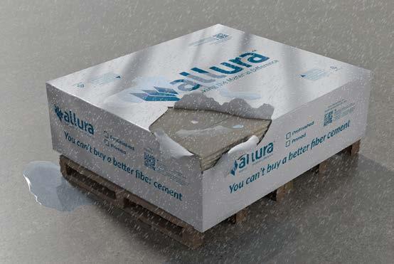
Allura® fiber cement siding products must be covered and stored off the ground, on a clean, flat, and level surface. The product should be stored in its original packaging and in a covered area such as a garage to protect the product from the weather.
If a covered area is not available, place pallets on wood blocks to allow air flow underneath the pallet and cover the product with an additional waterproof covering, such as a tarp.
IMPORTANT: If Allura® products become saturated, the product must be laid on a flat surface and allowed to dry completely before installation. Installing wet or saturated boards may result in the butt or end joints opening up after installation, efflorescence or other product issues that require repair or replacement.
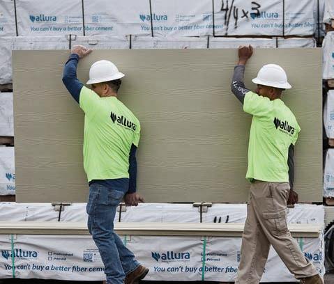
When handling Allura® products, do not slide boards when removing them from the pallet as sliding one board against the other may mar the surface of the board below. The product should always be carried by the narrow edge and evenly supported. Allura® products greater than 24 inches wide should always be carried by two people.


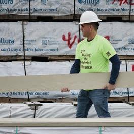



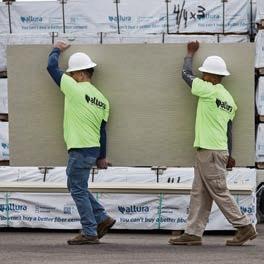
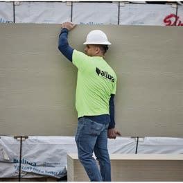
IMPORTANT: Carrying Allura® products flat causes excessive bending which can result in damage to the product. If prefinished, it may also damage the Allura® Spectrum coating.
Allura® product with Allura® Spectrum coating is packaged with slip sheeting between each piece. Ensure that the slip sheeting stays between the boards to protect against surface marring, boards sticking together, and moisture. If handled incorrectly, the surface of prefinished boards will scratch.
Allura® recommends certain tools for cutting and drilling fiber cement products safely consistent with our best practice recommendations. Consult tool manufacturer instructions for the safe operation of specific tools. Allura® accepts no liability for their use or misuse.
When cutting Allura® products, support the board along its length and near the cut. To avoid breakage, use extra care when cutting near the edge. Cover the cut table with a piece of carpet or soft cover to avoid scratching the face of the siding.
IMPORTANT: When cutting Allura® primed products, seal all cut edges with 100% acrylic latex paint or primer. When cutting Allura® Spectrum Products, use only Allura® Spectrum touchup paint to seal all cut edges.
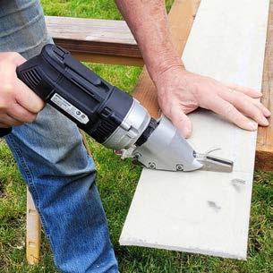
Shears may be used indoors or outdoors and generate virtually no dust. Shears can be used for making straight and radius cuts. When using shears, cut with the product face down and take care to avoid edge delamination. Shears cannot be used to cut Allura® Trim products.
Power saws should only be used in outdoor, well-ventilated areas. Use power saws with either a deflector to direct any dust away from the user’s breathing area or a collection box to capture the dust.
Use only poly-crystalline diamond-tipped blades to cut all Allura® Fiber Cement Siding Products and a carbide tipped blade for cutting Allura® Trim products.

When using a circular saw, cut with the board face down. When using a miter saw, cut with the board face up.
IMPORTANT: Allura® recommends that a HEPA vacuum system be used in conjunction with circular or miter saws. Always use a vacuum equipped with a HEPA filter to help minimize the amount of respirable dust during power saw cutting and clean-up.
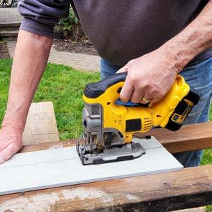
Jig saws should only be used in outdoor, well-ventilated areas. Jig saws equipped with carbide-tipped blades are typically used to cut service openings, curves, radii, and other irregular shapes in Allura® products. When using a jig saw, cut with the board face down.
Only drill outdoors in well-ventilated areas. Use masonry drill bits for smaller holes or a carbide tipped hole saw for larger holes.
When Allura® fiber cement product is cut or drilled, it can generate very fine (respirable) dust. The dust may contain crystalline silica, which can pose a health risk if inhaled. Over time, long-term occupational over-exposure to respirable silica dust can cause lung diseases including silicosis, lung cancer and other health issues.
The Occupational Safety and Health Administration (OSHA) regulates workplace exposure to silica dust and sets exposure limits for dust, chemicals and other materials that employees may be exposed to at work or on a jobsite. OSHA requires employers to take specific actions to protect workers on construction sites based on the amount of silica dust they are exposed to. The updated OSHA standard reduces the permissible exposure limit (PEL) for silica dust by about 80% – from 250 μg/m³ to 50 μg/m³ – over an 8-hour period.
If you have concerns about dust exposure or compliance with OSHA regulations, consult with a qualified industrial hygienist (IH). A directory of independent IH consultants can be found at www.aiha.org.
Allura® makes no representation or warranty that use of a particular cutting option will assure your compliance with OSHA rules or applicable laws and safety requirements.
DO NOT grind or cut with a power saw indoors. Use manual, pneumatic or electric shears designed for cutting fiber cement.
Position cutting station in a well-ventilated outdoor area so that airflow blows dust away from the user and others near the cutting area. It is best practice to use tools that minimize dust production or can capture dust at the point of production. For construction sites, OSHA has deemed that cutting fiber cement outdoors with a circular saw having a blade diameter less than 8 inches and connected to a commercially available dust collection system per manufacturer’s instructions results in exposures below the OSHA Permissible Exposure Limit (PEL) for respirable crystalline silica, without the need for additional respiratory protection.
When cleaning up dust and debris from cutting Allura® products, never use a broom or brush if the debris material is dry. Use wet dust suppressions methods, sweeping compound, or use a HEPA vacuum to collect dust.
DANGER: May cause cancer if dust from product is inhaled. Causes damage to lungs and respiratory system through prolonged or repeated inhalation of dust from product. Refer to the current product Safety Data Sheet before use. The hazard associated with fiber cement arises from crystalline silica present in the dust generated by activities such as cutting, machining, drilling, routing, sawing, crushing, or otherwise abrading fiber cement, and when cleaning up, disposing of or moving the dust. When doing any of these activities in a manner that generates dust you must (1) comply with the OSHA standard for silica dust and/or other applicable law, (2) follow Allura cutting instructions to reduce or limit the release of dust; (3) warn others in the area to avoid breathing the dust; (4) when using mechanical saw or high speed cutting tools, work outdoors and use dust collection equipment; and (5) if no other dust controls are available, wear a dust mask or respirator that meets NIOSH requirements (e.g. N-95 dust mask). During clean-up, use a well maintained vacuum and filter appropriate for capturing fine (respirable) dust or use wet clean-up methods - never dry sweep.
WARNING: This product can expose you to chemicals including respirable crystalline silica, which is known to the State of California to cause cancer. For more information go to P65Warnings.ca.gov.
Before installing Allura® products, review and comply with all local building codes and regulations regarding wall construction. Establishing a structural fastening surface sufficient to meet the requirements outlined in this manual is the responsibility of the property owner, architect/designer, general contractor and/or installer.
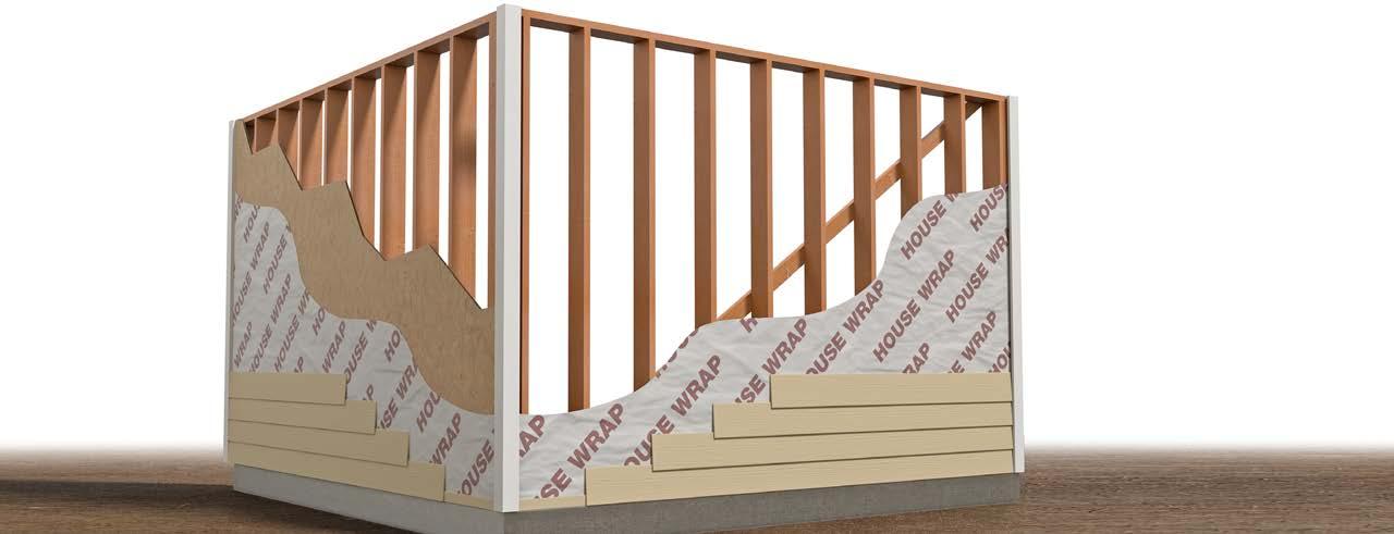
Plywood or OSB sheathing
Allura® Siding and Trim products can be installed over braced wood or steel studs spaced at a maximum of 24 inches on center. When installing Allura® products over steel studs, Allura® requires a minimum 20 gauge and recommends a maximum 16 gauge. Steel framing that is outside this range may be too flimsy to provide adequate holding power or too heavy for some fastening systems.
Allura® products should be applied over a rigid sheathing, such as 7/16 inch OSB or 1/2 inch plywood, to provide a smooth, flat surface. Irregularities and unevenness in framing (or other wall assembly components such as fasteners not driven flush and/or button head fasteners) can telegraph through Allura® products if not corrected prior to installation. Do not install Allura® products over questionable wall construction.
Weather-resistant barrier
Installing Allura® products over non-structural sheathing, such as solid-foam insulation board or gypsum, is acceptable if the combined thickness between the structural framing and Allura® product is 1 inch thick or less and the Allura® product is fastened through these products and into structural framing. Non-structural sheathing thickness in excess of 1 inch creates a condition where Allura® Fiber Cement Siding products cannot be properly attached to the existing structural surface (e.g. framing members, steel studs, or structural sheathing).
When installing over nonstructural materials in excess of 1 inch you must reestablish a structural framing surface to attach Allura fiber cement products. Allura® does not provide instructions for wall design or assembly that specifically relates to the fastening requirements for reestablishing a structural fastening system over non structural sheathings.
NOTE: Heavy building products and components such as roofing, drywall and floor coverings should be stored throughout the structure prior to the installation of the siding. Distributing the weight in this manner will reduce the possibility of floor plate compression on two or more story homes.
A weather resistant barrier is required in accordance with local building code requirements. The water-resistive barrier must be appropriately installed with penetration and junction flashing in accordance with local building code requirements. Allura® will assume no responsibility for water infiltration.
“Exterior walls shall provide the building with a weather-resistant exterior wall envelope. The exterior wall envelope shall include flashing, as described in Section 1404.4. The exterior wall envelope shall be designed and constructed in such a manner as to prevent the accumulation of water within the wall assembly by providing a water-resistive barrier behind the exterior veneer, as described in Section 1403.2, and a means for draining water that enters the assembly to the exterior. Protection against condensation in the exterior wall assembly shall be provided in accordance with Section 1404.3.
1. A weather-resistant exterior wall envelope shall not be required over concrete or masonry walls designed in accordance with Chapters 19 and 21, respectively.
2. Compliance with the requirements for a means of drainage, and the requirements of Sections 1403.2 and 1404.4, shall not be required for an exterior wall envelope that has been demonstrated through testing to resist wind-driven rain, including joints, penetrations and intersections with dissimilar materials, in accordance with ASTM E331 under the following conditions…”
When using Allura® Siding and Trim Products, make sure that roof flashing, water table flashing, window and door flashing, and flashing for other building envelope penetrations are properly installed and lapped so that moisture drains down and to the exterior.
Painted or coated aluminum flashings are recommended. Allura® does not recommend the use of mill finished, raw aluminum flashing or any other product that may bleed or adversely react with cement products. Manufacturers of ACQ and CA preservative-treated wood recommend spacer materials or other physical barriers to prevent direct contact of ACQ or CA preservative-treated wood and aluminum products.
IBC Code Reference: 1404.4 Flashing
“Flashing shall be installed in such a manner so as to prevent moisture from entering the wall or to redirect that moisture to the surface of the exterior wall finish or to a water-resistive barrier complying with Section 1403.2 and that is part of a means of drainage complying with Section 1402.2. Flashing shall be installed at the perimeters of exterior door and window assemblies, penetrations and terminations of exterior wall assemblies, exterior wall intersections with roofs, chimneys, porches, decks, balconies and similar projections and at built-in gutters and similar locations where moisture could enter the wall. Flashing with projecting flanges shall be installed on both sides and the ends of copings, under sills and continuously above projecting trim. Where self-adhered membranes are used as flashings of fenestration in wall assemblies, those self-adhered flashings shall comply with AAMA 711. Where fluid applied membranes are used as flashing for exterior wall openings, those fluid applied membrane flashings shall comply with AAMA 714.”
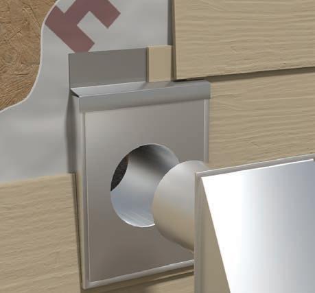
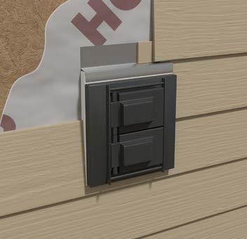
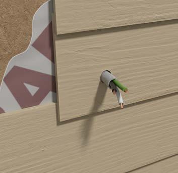
For building penetrations 1-1/2 inch diameter or larger, such as hot air vents, hose bibs, and light and electrical outlets, a mounting block must be installed to restore the weather-resistant barrier of the home after cutting a hole for the penetration. No mounting block is required for conduits, wires or pipe less than 1-1/2 inch diameter.
Mounting blocks can be created from cutting sections of 4/4 or 5/4 thick Allura® Trim or by using prefabricated mounting blocks and flashing products that are available for purchase. Mounting blocks should be a minimum of 3 inches larger than the penetration. A sloped z flashing must be installed over the top of all mounting blocks.
Refer to the illustrations shown here for the proper cutting and installation of Allura® Fiber Cement Siding around trim blocks for a variety of external pipe and receptacle penetrations.
The trim block must be mounted directly over the sheathing and weather-resistant barrier. For pre-existing vent pipes and hose bibs, the trim block must be cut into two pieces to retrofit around the existing pipe. The dividing cut must be a minimum 22.5-degree weather cut angle.
Allura Fiber Cement Siding Weatherresistive barrier
Minimum 22.5° weather cut Cut trim block into two pieces to retrofit around existing vent
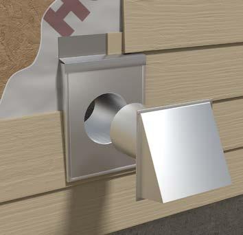
For hot air vents including dryer vents, stove vents, furnace and heater exhaust, it is important to move the air away from the building envelope. As the vent is installed, a path for that moisture to leave the area should be identified. Any vent piping is required to have blocking and flashing at the penetration.
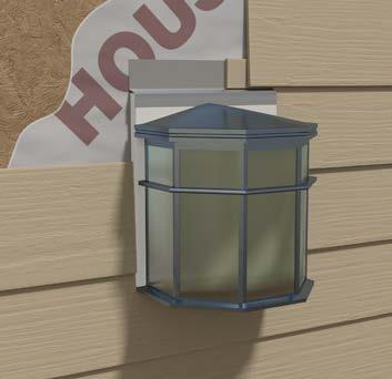
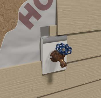
Vinyl Mount Master
Sheathing Z Flashing
Don't caulk 1/4" gap Starter strip
Weatherresistive barrier
Allura Fiber Cement Siding
Sheathing
Starter strip
Z Flashing
Don't caulk 1/4" gap 1/8" gap
Weatherresistive barrier
Allura Fiber Cement Siding
Seal with foam or caulk
Allura® recommends certain tools for fastening fiber cement products, consistent with our best practice recommendations. Consult tool manufacturer instructions for the safe operation of specific tools. Allura® accepts no liability for their use or misuse.
Allura® Siding products can be hand nailed. When hand nailing, use a smooth-faced hammer. Waffle-headed hammers can mark the face of the siding. Seat the bottom of the nail head flush with the surface of the board. Do not over drive the nail. When hand nailing, predrilling is recommended.
Pneumatic nail guns
Pneumatic siding and roofing nailers can be used to attach Allura® Siding products to structural wood substrates. A flush mount attachment on the pneumatic tool is recommended. This will help control the depth the nail is driven. If setting the nail depth proves difficult, choose a setting that under drives the nail and then seat nail with a smooth faced hammer.
When using a pneumatic nailer, set the air pressure regulator on the air compressor to the appropriate PSI setting and test the pressure for over/under driving the fastener on a scrap piece. Siding must be fully supported against a solid surface when the gun is actuated. In line regulators are also available to regulate pressure for each individual air hose.
Do not use framing nailers or staple guns. Pneumatic finish nail guns should be used with Allura® Trim only.
Screw Guns
Use screw guns when attaching to steel framing. Screw guns can also be used when attaching to structural wood substrates. Positive or adjustable clutch screws guns with 2000 to 2400 RPM’s are recommended to run screws. DO NOT discard adjustable clutch adapters. This will result in overdriven screws. Power bits shall properly fit the drive recess of the screws and should be replaced when worn.
All fasteners must be corrosion-resistant, hot-dipped galvanized or stainless steel. Stainless steel fasteners are recommended when installing Allura® products near
the ocean, or in very humid climates. Allura® does not recommend the use of Electro-galvanized nails because they corrode faster, especially in coastal areas. Fasteners used to attach Allura® products to ACQ and CA preservative-treated wood shall be of hot dipped zinc-coated galvanized steel or stainless steel and in accordance to 2009 IRC R317.3 or 2009 IBC 2304.9.5.
Allura® is not responsible for corrosion resistance of fasteners. Do not use staples, clipped head, or aluminum fasteners to install Allura® products. Finish nails may only be used when installing Allura® Trim.
Ensure fasteners meet Allura’s® General Fastening Requirements when attaching to wood or steel framing. When attaching through nonstructural materials, the fastener length may need to be increased to satisfy fastener embedment requirements.
Fasteners must be driven perpendicular and heads must be proud to the surface of the siding. Do not over drive the fasteners. When a fastener is overdriven its holding power is reduced and creates an entryway for moisture.
Fastening
When using nails, a minimum of 1-1/4 inches must penetrate structural framing. The minimum penetration may include the thickness of the structural sheathing (7/16 inch OSB or ½ inch plywood).
When using screws, a minimum of 3/4 inches must penetrate the structural framing.
Use self-tapping screws specifically designed for use with fiber cement. Screws must penetrate a minimum of 1/4 inches or three threads into metal framing. When screws are used to attach to steel studs/furring, the screws shall have wing tips. If screws do not have wing tips, then pre-drilling is required.
Steel
The fastener specifications table provides a list of fasteners that can be used to install Allura® fiber cement products. Please refer to the applicable Code Evaluation Report to determine which fastener meets your wind load design criteria and fastening substrate conditions.
It is the responsibility of either the property owner, design professional, contractor, or installer to select the appropriate fastener and if applicable, to demonstrate an alternate fastener’s equivalency to the fastener listed in the applicable Code Evaluation Report.
2 in. x 16 ga.

Finish Nail
2 in. x 0.092 in. x 0.221 in.

Siding Nail
2 in. x 0.092 in. x 0.221 in.

Ring Shank Siding Nail
1.75 in. x 0.120 in. x 0.375 in.
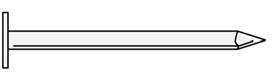
Roofing Nail
1.75 in. x 0.120 in. x 0.375 in.
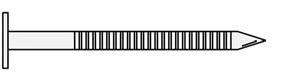
Ring Shank Roofing Nail
#8 x 1 5/8 in. x 0.375 in.
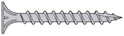
Ribbed Wafer-Head Screw
#10 x 1.5 in. x 0.473 in.
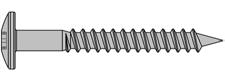
SFS intec TW-S-D12
#9 x 1 5/8 in. x 0.375 in.
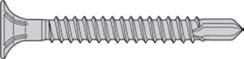
Ribbed Wafer-Head Screw
Allura® specifies clearances to ensure the long-term durability of their products and the buildings on which they are installed. Failure to provide the proper clearances, as specified below, may affect performance of the building system, violate building codes or Allura® requirements, and may void any warranty on the products.

Roof to wall transitions shall be flashed to the wall. When applicable, step flashing should be installed at every roofing shingle course. The water-resistive barrier on the wall should lap over the step flashing.
• A clearance of 1-2 inches must be maintained between Allura® siding and trim products and the roof.
If rain gutters are present, extend the shingles at least 1 inch out from the fascia to direct water directly into the gutters. If rain gutters are not present, extend the valley flashing at least 2 inches out from the corner to direct water further away from the building.
The above requirement also applies to roof valleys at any other locations where the fascia runs into a roof line such as dormer valleys and roof-to-roof intersections.
When using Allura® Trim is used in rake or fascia applications, a drip-edge flashing must be installed to the roof sheathing overlapping the trim. Choose a drip edge design that effectively channels water away from the face of the trim and into gutters if present.
Where the roof begins at its lowest point, install a kickout flashing to divert roof runoff water away from the siding. The water-resistive barrier on the wall should lap over the step flashing and kickout flashing.
• Kickout flashing shall be min 4 in x 4 in with a 100° - 110° bend/kickout.
• Maintain a 1 inch clearance between the siding and the gutter end-cap. Never terminate gutters against siding or trim.
All horizontal penetrations such as window and door heads, band boards, water tables etc. require a z flashing. This flashing should be installed with a positive slope in such a way that it promotes proper drainage and does not allow moisture to pool on top of the flashing
• A 1/4 inch clearance must be maintained between Allura® siding and trim products and any horizontal flashing. Do not caulk between the siding and the horizontal flashing.
Notching Allura® Products around Wall Openings
When notching Allura® siding products around openings and penetrations (i.e. doors, windows, light, spigot and electrical blocks), first drill holes using a 1/4 inch masonry bit to the inside of intersecting corner marks. Proceed to finish cut out by plunge cutting to holes with a circular saw, using a jigsaw with a carbide tipped blade, or a hand saw. Do not allow the blade to cut through the predrilled holes as this will create a weak spot that can crack during and/or after installation.
A minimum 1/8-inch clearance must be maintained when siding meets a vertical termination, such as windows, doors, trim, corners, penetrations, etc. When butting siding to materials such as brick, stone, stucco, or block, install ‘L’ flashing and leave minimum 1/8 inch clearance between siding and flashing.
Caulk all vertical terminations or transitions unless siding terminates into a pocket or “J” channel receiver.
Maintain minimum ¼ inch gap between siding and z flashing at top of block. Do not caulk. Maintain a minimum 1/8 inch clearance where siding meets block on vertical sides and bottom of block, caulk at these locations. Follow Notching requirements in Section 5.5. for cutting siding products around penetrations.
Allura® products must not be installed such that they remain in contact with standing water.
• A clearance of 1-2 inches must be maintained between Allura® siding and trim products where they meet decks, walkways, steps, driveways or any other solid surfaces.
Allura® products must not be installed such that they remain in contact with standing water.
• Allura® products must be installed with a minimum 6 inch clearance to the ground on the exterior of the building. Clearances greater than 6 inches may be required in accordance with local building codes.
Before you begin to caulk, remove any dust or debris. The caulk or sealant should be color matched or paintable. It should be compatible with both Allura® Fiber Cement Siding and the materials used for the trim. Check the gloss and texture of the caulk to make sure it is compatible with the paint.
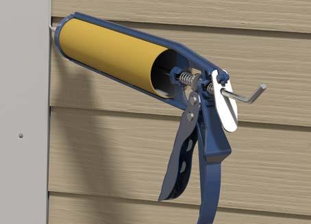
For best results, use an elastomeric joint sealant complying with ASTM C920 Grade NS (Class 25 or higher), or use a latex joint sealant complying with ASTM C834. Caulking/Sealant must be applied in accordance with the caulking/sealant manufacturer’s written instructions.
Caulk wherever siding meets the trim at non-self-flashing penetrations and vertical terminations (i.e. at doors, windows, mounting blocks etc). It is never acceptable to caulk between Allura® siding and horizontal flashing at areas such as window and door heads, band boards, mounting blocks, and floor line breaks. Do not caulk areas where Allura® Fiber Cement Siding has been inserted into J-channel or another pocket or accessory.
When installing primed Allura Products, apply high-quality, exterior-grade acrylic topcoats within 180 days of installation. Two finish coats of paint are recommended. Before applying the finish coat, always follow the paint manufacturer’s recommendations for surface preparation and paint application. Back-rolling is recommended if the siding is sprayed. Do not use stain, oil/alkyd base paint, or powder coatings on Allura® products. Never apply paint to wet or saturated products.
After cutting any Allura® Product, use a soft cloth to gently wipe any residue or construction dust left on the product. Prime or paint all cut edges of products before installing. Factory edges should be used at all field butt joint locations. When a non-factory edge is installed in the field, it must be sealed prior to installation. All other vertical terminations must be caulked.
As with any pre-finished building product, care should be taken when handling and cutting Allura Spectrum products. Only use Allura touch up kits with Allura Spectrum Products. Check the color and accessories are not damaged prior to use. Mix the paint well. Test the color on the sample piece or hidden area of before applying.
Use a soft cloth to gently wipe any residue or construction dust left on the product. The edge coater is for use on non-factory cut edges only. Edge coating is required for any field cuts to seal the edges and make joints less visible.
Use paint pen applicator to touch-up areas that are smaller than a dime, such as nail heads and very small nicks and scratches. Touch up should be used sparingly and excess paint should be removed. In areas larger than a dime, Allura recommends the piece affected be removed and replaced.
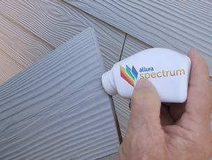
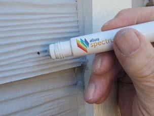
Do not allow Allura Spectrum touch-up to freeze. Apply touch-up when temperature of the air and the siding products is above 40°F (4°C).
Allura does not warrant the use of third party touch-up or paints used as touch-up on Allura Spectrum products.
The siding should be inspected periodically with the following routine maintenance performed as necessary. Re-fasten any loose siding and cut back any trees or shrubs that touch the siding. Correct the drainage in any spots where water is retained in contact with the siding. Long term contact with water may result in discoloration. Avoid regularly wetting the siding with lawn sprinklers since water in many locales contains rust or minerals which may discolor the siding’s surface, shorten the life of the paint, and encourage the growth of mildew and fungus.
Allura recommends periodic washing (every 6 to 12 months). Mix water with a mild household cleaner, such as liquid dish washing soap. Apply the solution with a cloth, sponge, or soft brush (such as a car wash brush). Immediately follow all washing by rinsing thoroughly with plain water from a garden hose. Never use harsh cleaners, abrasives, or strong solvents because they may damage the paint or surface. If the dirt does not wash off, it may be mildew or a fungus growth.
Do not power wash Allura Fiber Cement products as it can cause moisture intrusion, damage and discoloration.
Fill dents, chips using a good quality cement patching compound (acrylic mortar patch), which can be found at your local Home Center or Hardware Store. Allura does not approve the use of caulking or cementious patches to touch up, fill or repair nail heads, nail holes or other surface imperfections.
Replace siding and trim products in accordance with Allura® ’s written installation instructions.
When caulk is in need of replacing, carefully remove existing caulk and replace with a high quality, paintable latex caulk. Caulking should be applied in accordance with the caulking manufacturer’s written application instructions.
Remove any damaged, chipped or cracked paint. Prior to repainting, make sure that the surface area is properly cleaned. Repaint immediately using a good quality 100% acrylic paint. For best results, please refer to your paint manufacturer’s written specifications for application rates and required topcoats.
NOTE: If the product has been finished/ painted in the field, please refer to your paint manufacturer’s recommendations for care and maintenance. If the product has been pre-finished with Allura Spectrum Finish, refer to the directions provided in this document.

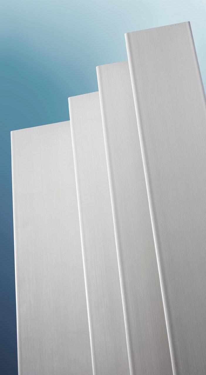
Allura Trim® boards come finished with either a factory primer or Allura® Spectrum Coating. The Allura® Spectrum Coating is a factory-applied, oven-baked finish available on a variety of Allura® products.
Allura® Trim
Allura® Trim, 4/4 and 5/4 boards are a decorative non-load bearing trim product. 4/4 board is 3/4 in. thick, 5/4 board is 1 in. thick, and are 12’ long. Allura® Trim is available in commonly used nominal widths ranging from 3 inches to 12 inches.
In addition to frieze, rake, window, door, and corner details, Allura® Trim 4/4 and 5/4 boards may be used to construct light blocks, column wraps and decorative scroll work.
Allura® Trim Battens
Allura® Trim® Battens are a decorative non-load bearing trim product. Allura® Trim Battens are available in 4/4 and 5/4 thickness, 12 foot lengths and 3 inch or 4 inch nominal widths.
Review the general cutting, fastening, and wall preparation instructions in Sections 1 through 6 of this guide.
Allura trim is a decorative non-load bearing trim product. Before you install Allura trim, review and comply with all local building codes and regulations regarding wall construction. Establishing a structural fastening surface sufficient to meet the requirements outlined in this manual is the responsibility of the property owner, architect/designer, general contractor and/or installer. Design the wall assembly to ensure that all appropriate wind load and anchoring requirements are met.
IMPORTANT: Seal all primed Allura product cut edges with 100% acrylic latex paint or primer prior to installation. For Allura Spectrum Products, use only Allura Spectrum touchup paint.
For trim products use a circular saw equipped with a carbide tipped blade, NOT a polycrystalline diamond tip blade.
Fasten Allura Trim from one end to the other. Never fasten from both ends to the middle—it will stress the trim board. Drive the fastener perpendicular and flush to the surface of the trim. Do not over drive the fasteners. When a fastener is driven below the surface of the trim, its holding power is reduced and it creates an entryway for moisture.



Use only corrosion resistant or stainless-steel fasteners. Refer to the chart below for fastener options to determine the proper fastener for your application.
Follow the fastening requirements as shown below for width of trim being installed. Note that 3-inch – 4-inch trim is the only pattern where fasteners alternate sides every 16 inches.
When assembling inside or outside corners always weather cut adjoining ends using a minimum 22.5° angle so moisture will shed down and away from the structure. Ensure weather cuts are a minimum of 12 inches apart on adjacent trim pieces.
Allura recommends the use of 5/4 trim boards for all lap siding butt to trim applications.
Ensure Allura Trim is fastened according to the fastener schedule and attached to framing and/ or blocking.
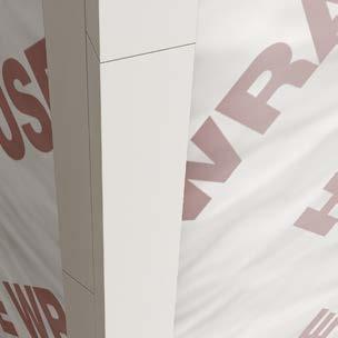
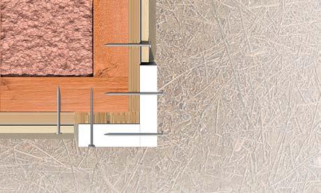
Inside corners can be made with either a single Allura Trim 4/4 or 5/4 board in the corner, or with one board on each wall depending on the desired look.
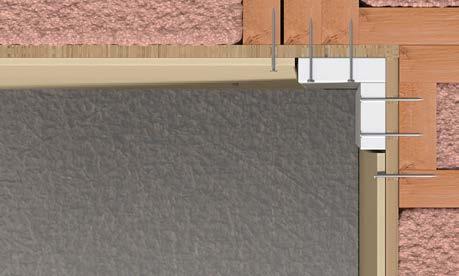
Leave appropriate gap and caulk
Trim
Leave appropriate gap and caulk
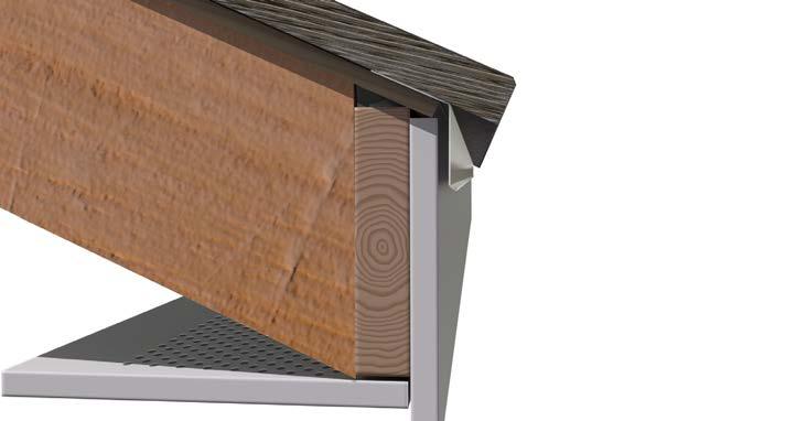
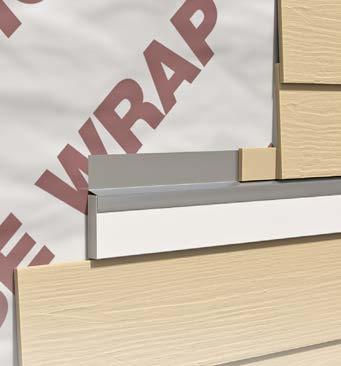
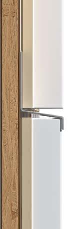
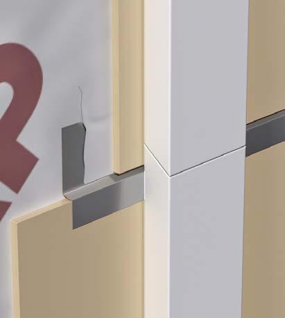
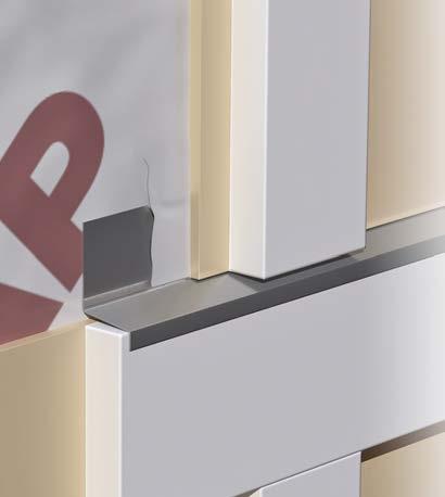
For horizontal trim applications a z flashing incorporated into the WRB must be used (e.g. window and door heads, band boards, and water tables). For horizontal trim terminating into an eave or soffit overhang a z-flashing is not required. When trim is used as fascia and rake boards it must be covered with a drip edge. For longer runs use a bevel cut to join lengths.
Roofing
Roof underlayment
Install fascia and rake trim over a solid wood substrate. Bevel cut adjoining ends and place 2 fasteners every 12” to 16”. After the fascia and rake trim is installed, a vinyl, coated aluminum or galvanized drip-edge flashing must be installed to the roof sheathing overlapping the fascia and rake boards.
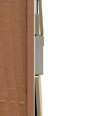
For band board installation follow fastening patterns and clearance requirements as called out in this manual. Always fasten to framing members spaced no greater than 24 on center, and bevel cut adjoining ends on longer runs, Follow all z flashing requirements and siding starter requirements above z flashing. Caulk siding termination at underside of band board.
When installing frieze boards under a soffit or eave, butt the trim to the bottom of the soffit panel. No z flashing or caulk is required at this location. Cut top course of siding to fit under frieze board leaving a minimum 1/8 inch clearance between the panel and the trim board. Caulk at this location and follow trim fastening schedule shown in this manual attaching to framing members spaced no greater than 24 inch on center.
Bevel cut adjoining edges on longer runs.
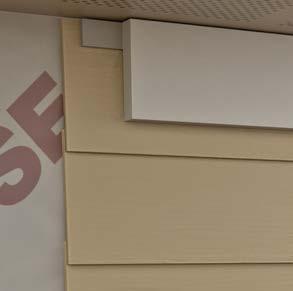
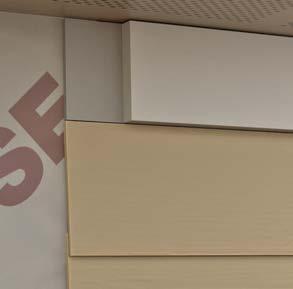
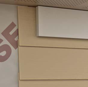
For vertical trim applications around windows and doors trim should be fastened flush to window or door frame. Adjoining trim ends can be mitered or square cut at the corner.
To trim window using square cut (cap over method) cut the bottom piece of trim equal to the width of the window frame. Attach under sill. Next cut two vertical side pieces equal to the length of the window frame plus the width of the sill trim.
Install flush to bottom edge of sill trim and top of window frame. Lastly cut top piece of window trim equal to width of top window frame plus 2 x width of trim.
Mount this piece even to outside edges of vertical trim pieces. Following fastener spacing shown for trim in this manual. Install siding after opening has been trimmed and maintain all vertical and horizontal clearances. Follow flashing and caulking guidelines as required.
To trim doors use the same method excluding the sill trim. Be sure to maintain proper clearances at hardscapes or grade. Install siding after opening has been trimmed and maintain all vertical and horizontal clearances. Follow flashing and caulking guidelines as required.
Side trim pieces go to the top of the window.
Header piece spans the window including the side trim pieces.
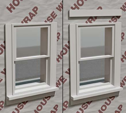
Bottom trim piece is the width of the window.
Starter strip
Weather resistive barrier
Do not caulk between the siding and the flashing.
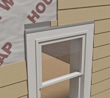
Flashing 1/4" gap
1/8" caulked gap is left between siding and the side trim pieces.
For windows and doors with attached nailing flanges, shim between the substrate and the trim to build wall out and allow trim to sit parallel to the wall.
Center Allura Trim Battens over vertical panel joints and fasten the batten through the panel and into framing. Ensure battens that are not over panel joints are also centered over and nailed to framing. Vertical batten edges do not need to be caulked. The panel butt joint behind the batten should be treated per the siding manufacturers’ recommendations prior to installing the batten.
Allura Panel siding
Allura Trim boards
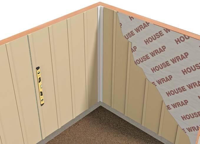
Snapped chalk line guides the installation
Weather resistant barrier
When installing Allura Trim Battens, the battens must either be:
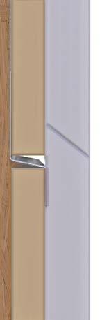
• Weather cut and joined over horizontal transitions using a minimum 22.5 degree angle. The weather cut slope should begin 1/4” above the horizontal z-flashing and slope away from the wall.
• Installed with the proper clearances both above flashing and below band board.
DO NOT bridge floors with Allura Panel or Allura Trim Battens. A horizontal joint shall always be created between floor
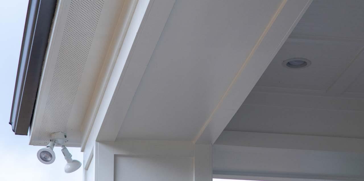
Allura Soffit® comes finished with either a factory primer or with an Allura® Spectrum Coating. The Allura® Spectrum Coating is a factory-applied, oven-baked finish available on a variety of Allura® products.
Allura® Soffit for eave and rake applications are 8 ft. and 12 ft. long, ¼ in. thick and pre cut in a range of widths. The product is available vented or non-vented boards. Allura® Soffit panels come in either a smooth finish or Traditional Cedar textured finish.

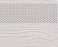

AVAILABLE TEXTURES *
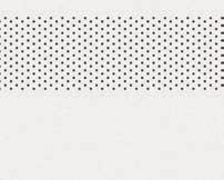
* Check market availability, as products may vary.
12' Vented/Non-Vented ¼" 16" 12'
Vented/Non-Vented ¼" 12" 12'
Review the general cutting, fastening, and wall preparation instructions in Sections 1 through 6 of this guide.
Allura Soffit products are specifically designed and tested for ceiling and overhead use only.
Before you install Allura Soffit products, review and comply with all local building codes and regulations regarding wall construction. Establishing a structural fastening surface sufficient to meet the requirements outlined in this manual is the responsibility of the property owner, architect/designer, general contractor and/or installer. Design the wall assembly to ensure that all appropriate wind load and anchoring requirements are met. Consult the latest version of the QAI Code Evaluation Report CERus-1012 for guidance on approved fasteners.
IMPORTANT: Allura soffit may be used in soffit or porch ceiling panel applications only. Do not install Allura Soffit on vertical walls.
Ventilation
Proper attic ventilation is important for any home. The information provided here may under certain circumstances not result in enough ventilation. The IBC guideline requires that any attic or space between the top floor, ceiling, and roof must be ventilated.
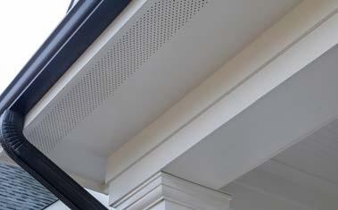
Note: Allura vented soffit provides 6.9 square inches per lineal foot of net free airspace. When installing vented soffit be sure to face vented portion of the board toward the fascia for maximum airflow.
Blocking Rafter
Ledger
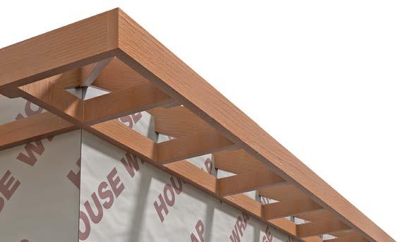
All edges of the soffit panels must be supported Immediate supports should be no more than 24" OC
Subfascia
Allura Soffit must be attached to structural framing members spaced no greater than 24 inch on center.
Framing of rakes and eaves must include a structural subfascia and a 2”x 2” (minimum) ledger board along the wall, with the bottom edge of the ledger board level and parallel to the structural sub fascia for attachment of soffit panel. For soffit wider than 12 inches 2 x perpendicular blocking must be installed spaced no greater than 24 inches on center.
Less than or equal to 12ʺ wide soffit. Greater than 12ʺ wide soffit.
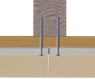
Fasteners must be hot dipped, non-corrosive or stainless steel 6d common nail. Attach Allura Soffit with fasteners spaced no greater than 12” OC on all edges and intermediate blocking. Ensure perimeter fasteners are 3/4" from the front and back edges, 3/8" from the butt ends, and 2" from the corners. For all sizes install panels with all edges butted in moderate contact centered on framing member or blocking.
Do not use finishing nails or staples.
When using receiving channel for soffits make sure panels are cut leaving an 1/8 inch gap when inserted into receiver.
In all cases seal all cuts with 100% acrylic latex paint or primer. When using Allura spectrum prefinished products always use Allura spectrum touch up kits to seal edges.
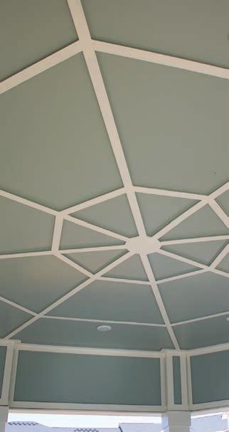
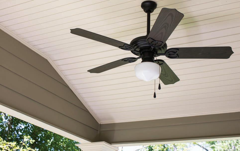
Allura Soffit® panels come finished with either a factory primer or with an Allura® Spectrum Coating. The Allura® Spectrum Coating is a factory-applied, oven-baked finish available on a variety of Allura® products.
Soffit Panels
Ceiling Specifications

AVAILABLE TEXTURES * * Check market availability, as products may vary.
Review the general cutting, fastening, and wall preparation instructions in Sections 1 through 6 of this guide.
Allura Porch Ceiling Soffit products are specifically designed and tested for ceiling and overhead use only.
Before you install Allura Porch Ceiling Soffit products, review and comply with all local building codes and regulations regarding wall construction. Establishing a structural fastening surface sufficient to meet the requirements outlined in this manual is the responsibility of the property owner, architect/designer, general contractor and/or installer. Design the wall assembly to ensure that all appropriate wind load and anchoring requirements are met.
Consult the latest version of the for guidance on approved fasteners.
Allura Porch Ceiling Soffit may be used in ceiling applications only. Do not install Allura Soffit on vertical walls.
Allura Porch Ceiling Soffit must be attached to structural framing members spaced no greater than 24-inches OC. All panel edges must be supported by framing.
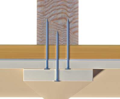
Additional framing may be required for proper fastening. Allura recommends a double stud at panel joints for an easier installation.

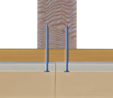
Attach Allura Soffit Porch Ceiling Panels with fasteners spaced no greater than 6” OC on all edges and intermediate framing or blocking. Ensure perimeter fasteners are 3/8" from all edges and 2" from the corners. Install panels with all edges butted in moderate contact centered on framing member or blocking.
Do not use finishing nails.
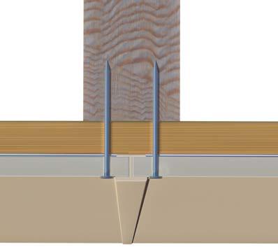
Panel ends may be lightly butted in moderate contact, the ends may be gapped 1/8 in. and caulked, joints can be covered with batten strips, or panels may be joined with H-molding. When using H-moldings, make sure panels are cut to size to allow for leaving an 1/8 inch gap when inserted into receiver.

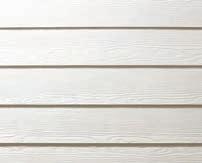

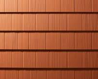
Perfection Shingles
Review the general cutting, fastening, and wall preparation instructions in Sections 1 through 6 of this guide.
Allura Lap Siding is specifically designed to be used in exterior, flat vertical wall applications.
Before you install Allura Lap Siding products, review and comply with all local building codes and regulations regarding wall construction. Establishing a structural fastening surface sufficient to meet the requirements outlined in this manual is the responsibility of the property owner, architect/designer, general contractor and/or installer. Design the wall assembly to ensure that all appropriate wind load and anchoring requirements are met. Consult the latest version of the IQAI Code Evaluation Report CERus-1012 for guidance on approved fasteners.
Starter Strip Installation
You must use a starter strip with Allura Lap siding. Locate the lowest point of the sheathing and snap a level chalk line 1-in. above the low edge of the sheathing. Rip a 1-1/2-in. piece of Allura Lap Siding for the starter strip. Align the top of the starter strip with the chalk line and fasten every 12-16-in. OC.
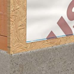
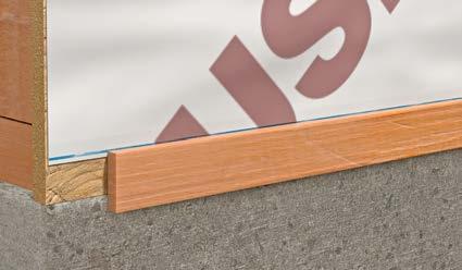
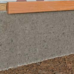
NOTE: Ensure the Allura Lap Siding, when installed, meets all clearance requirements including 6-in. above the finished grade or 1-in. above surfaces where water may collect.
6 inch
Snap a chalk line to ensure the first course of Allura Lap Siding is level and positioned 1/4-in. below the bottom edge of the starter strip. Measure and cut the plank to accommodate 1/8-in. gap at trim (or other transition break) on one end and center the other end over a framing member.
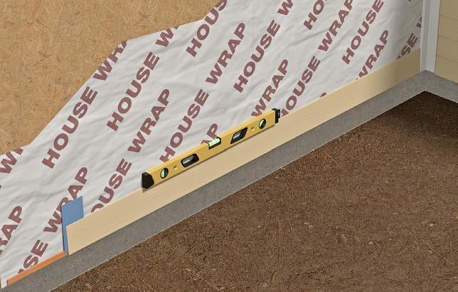
If cut ends are used in a butt joint between planks, Allura requires sealing the cut ends. For Allura Spectrum products, use the color-matched edge coater to seal the cut end.
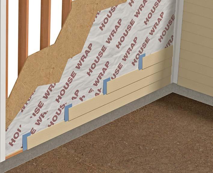
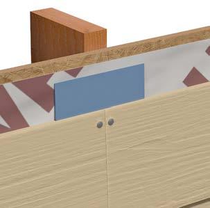
Flashing behind butt joints provides an extra level of protection against the entry of water at the joint. Allura® recommends 6-in. wide flashing at every joint that extends 1-in. over the course below. Joint-flashing material must be durable, waterproof materials that do not react with cement products. Examples of suitable material include finished coil stock, code compliant water-resistive barriers or Bear Skin.
6" joint flashing centered on panel joint
Extend 3" above top of panel
Sheathing
Extend 1" over panel below Weather resistant barrier
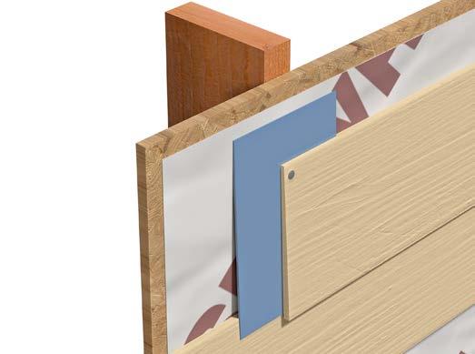
Check with local building code requirements for acceptable backflashing material.
Fasten Allura Lap Siding from one end of the plank to the other. Do not place fasteners in the center, unsupported area of the siding. If you are hand nailing or using screws, it may be necessary to predrill to help prevent the corners from breaking.
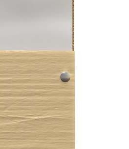
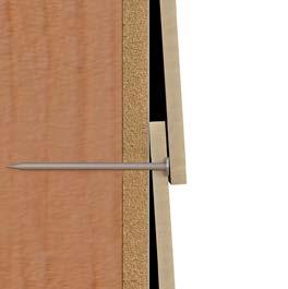
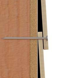
Determine if the siding method will be blind fastened or face fastened. Lap siding that is wider than 9.25-in. must be face fastened. Other factors that determine fastening method include wind load, exposure, wall construction, and type of fastener.
• Place the fastener 1-in. from the top of the panel and no closer than 3/8-in. from the ends.
• When blind nailing Allura® Lap Siding, Allura® recommends the use of nail placement adapters, such as the EZi gauge, to aid in maintaining proper nail placement. The adapter provides consistent placement of the nail one inch down from the top of the siding to the center of the nail while still allowing the depth adjustment to function properly. The adapter helps prevent high and low nail problems and the warranty issues that can result, such as loose siding, unwanted gapping, or rattling.
• Place the fastener 3/4-in. from the bottom of the overlapping panel. This will help ensure that the fastener penetrates both courses of siding. Place the fasteners no closer than 3/8-in. from the butt edge.
• Face fastening only to be used in conjuction with blind fastening when fastening a horizontal termination course or when replacing a board in the field.
Allura Lap Siding Course Layout
Prior to installing Allura Lap Siding, map out the joint pattern for each elevation to minimize waste and create a consistent stagger pattern. If snapping chalk lines up the wall in preparation for all siding courses, ensure each course of siding will overlap 1 1/4-in. over the course below. Stagger butt joints a minimum of 2 stud bays for 16-in. OC framing.
Never stack butt joints on consecutive lap courses.
Several different alignment tools and methods exist to ensure proper spacing and overlap of fiber cement products. Snapping chalk lines with proper spacing above each course as it is being installed is one way, however, there are alignment gauge devices that are easy to use, ensure a consistent reveal and speed up installation. Examples include PacTool Gecko Gauge or Malco® Overlap Gauge.
Once you have installed the starter strip and first course of Allura Lap siding, continue up the wall leaving a 1/8’’ gap at the corner trim, staggering subsequent courses. Butt joints in Allura lap siding should always be centered over and attached to structural framing. Whenever possible, factory finished ends should be used at butt joints.
TIP: When installing Allura Spectrum Prefinished Lap Siding, position the plank in the immediate area where the plank is to be fastened. Do not place the plank on the course below and slide into position. Doing so may scuff or scratch the Spectrum finish on the installed piece.
Caulking at Allura lap siding butt joints is not recommended for aesthetic reasons as the caulking and field applied finish or Allura Spectrum finish will weather differently. For the same reason, do not caulk exposed nail heads.
When a door or window intersects with siding courses, cut siding to fit leaving a minimum 1/8-in. gap on the vertical sides of the window or trim and ¼-in. gap over the top of the window or trim flashing. Notch planks to fit above and below windows and doors or other opening as needed (Refer to Section 5.5 for acceptable notching methods). Maintain proper clearances around the window trim and again, be sure to seal all cut edges.
Avoid placing butt joints directly above or below windows or above doors. Separate butt joints above and below the opening by at least one course of siding.
Add an extra stud if necessary for nailing the ends of the planks.
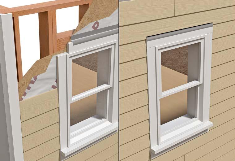
Pay special attention to window, doors, and corners that have been trimmed before the Allura siding is installed. Vertical trim boards may cover the studs beside windows or doors, or they may cover up corner studs leaving no room for nailing the siding. In these places add extra studs as needed.
NOTE: When installing Allura Fiber Cement Siding into a J-channel or other receiving channel, ensure that all cut edges have been re-sealed with Allura Spectrum touch up prior to insertion; do not caulk between the siding and the channel. Make sure all corners are properly flashed.
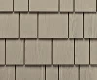
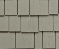
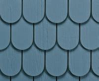
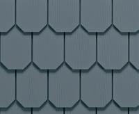
STRAIGHT EDGE Thickness
¼" 16" x 48" 7"
STAGGERED EDGE
Thickness
¼" 16" x 48" 6"
¼" 16" x 48" 7"
* Check market availability, as products may vary.
Review the general cutting, fastening, and wall preparation instructions in Sections 1 through 6 of this guide.
Allura Shake Products are specifically designed to be used in exterior, flat vertical wall applications.
Before you install Allura Shake products, review and comply with all local building codes and regulations regarding wall construction. Establishing a structural fastening surface sufficient to meet the requirements outlined in this manual is the responsibility of the property owner, architect/designer, general contractor and/ or installer. All Allura Shake products must be installed over structural rated wood sheathing (Minimum 7/16-in. OSB) with framing spaced no greater than 24-in. OC.
Fasteners may or may not hit framing/stud locations. Design the wall assembly to ensure that all appropriate wind load and anchoring requirements are met. Consult the latest version of the QAI Code Evaluation Report CERus-1012 for guidance on approved fasteners.
Starter Strip and Starter Course
To install Allura Shake products you must use a starter strip and a starter course. When installing Allura Shake products starting at the base of the structure, snap a level chalk line 1-in. above the lowest edge of the sheathing. When installing above a horizontal band board with z flashing, snap a level chalk line at 2-in. Rip a 1 ½-in. piece of Allura Lap Siding for the starter strip. Align the top of the starter strip with the chalk line and fasten every 12-in.-16-in. OC.
Next install a starter course of 8.25-in. Allura Lap siding with the bottom edge 1/4in. below the starter strip, placing fasteners 1-in. below top edge and into framing. This course ensures that the keyways are fully backed by fiber cement on the first course of Allura Shake.
If you are transitioning from less than 8.25-in. Allura Lap siding to Allura Shake siding, use 8.25-in. lap siding as your starter course at that transition.
WEATHER RESISTANT BARRIER
EXTERIOR SHEATHING
ALLURA SHAKE
ALLURA LAP SIDING
EXTERIOR SHEATHING
ALLURA STARTER STRIP
Staggered Edge
Straight Edge
Half Round

To begin shake installation start on the left end of the wall. Measure to furthest stud within 48 inches of the corner and trim panel to ensure the factory edge is centered on this stud. Allow for proper clearance at trim board. Align bottom edge of the shake panel with bottom edge of starter course. Fasten panel 3/8-in. in from each end and 1-in. above the top of keyway. Fasten 1-in. above every other keyway in the body of the panel. All panels will be fastened in this manner. Continue working from left to right butting panels in moderate contact. Cut finish piece at right end of wall to fit allowing for proper clearances.
Measure up from the top of the installed panels the same measurement as the exposure of the panel (ex. 6-in. for staggered edge shake). Make a mark on the wall and use this as your guide to install next course of siding at the proper exposure. Repeat this step for additional courses.
To begin the second course cut the panel so the butt joint lands on a framing member one stud cavity back from the butt joint in the first course. Fasten panel in manner shown above, again making sure to allow for required clearances and butt joint landing on framing. Continue to work left to right to complete course with full panels. Trim last panel to fit. Allow for clearances.
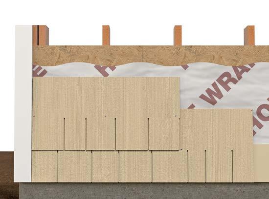
Always cut panels to ensure factory edge lands on butt joints and cut edge goes to trim. Seal cut edges with paint or primer before installation.
Note: If installing half-rounds, ensure the second course tabs are centered over the keyways on the first course.
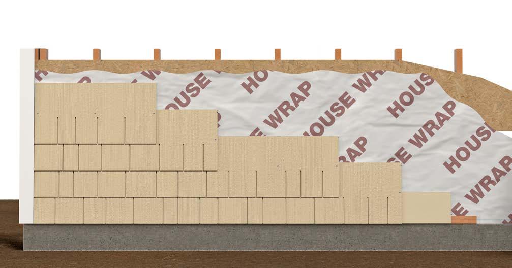
Repeat the steps above.
All Odd numbered courses (1,3,5…) will begin equal to the length of the panel used to start the first course.
All even numbered courses (2,4,6…) will begin with a panel equal to the length of the panel used to start the second course.
When a window or doorway breaks a course continue the application as if the opening were not there to ensure the random shake look is maintained.
Refer to and follow the instructions in Section 11.3 for installing the starter strip and starter course.
For best appearance, gable installations should end with a single half-round piece at the peak. To accomplish this, measure the height of the gable/wall in inches. Divide the height by the exposure (ex. 6-in. for staggered edge shake, 7-in. for half-rounds).
• If the answer is an even number, center the first course of half-rounds on a keyway.
• If the answer is an odd number, center the first course on a half-round.
• If using the straight or staggered edge profile, begin with a factory end touching the centerline.
Drop a plumb line to find the center of the gable. Locate the first piece relative to the centerline of the gable/wall.
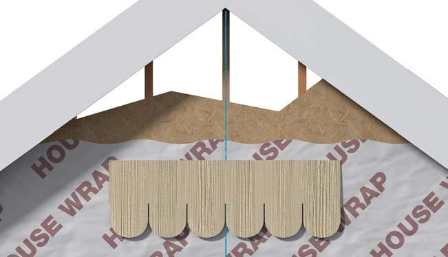
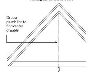
Align bottom edge of the shake panel with bottom edge of starter course and in reference to the plumb line. Fasten panel 3/8-in. in from each end and 1-in. above the top of keyway. Fasten 1-in. above every other keyway in the body of the panel. All panels will be fastened in this manner.
Once first panel has been properly located and fastened finish installing the first course to both the left and right sides butting the panel edges in moderate contact. Be sure to leave proper clearances at ends where cut panels meet trim or soffit.
Measure up from the top of the installed panels the same measurement as the exposure of the panel (ex. 6-in. for staggered edge shake). Make a mark on the wall and use this as your guide to install next course of siding at the proper exposure. Repeat this step for additional courses.
Starting on the left locate the first full panel installed in the first course. If installing half-rounds, offset the second course 21 inches (3-½ tabs) from the edge of the first full piece. This will align the center of the tab with the keyways in the first course. If installing staggered edge or straight edge, offset the second course 16-in. from the edge of the first full piece. Fasten panel as directed. Complete installation to both the left and right sides of this course.
NOTE: Make sure the tops of the keyways are concealed by the overlapping panel before fastening the siding.
Install the 3rd, 5th, and all other odd courses in the same horizontal position as the 1st course, maintaining the proper exposure.
Install the 4th, 6th, and all other even courses in the same horizontal position as the 2nd course, maintaining the proper exposure.
When a window or doorway breaks a course, continue the application as if the opening did not exist.
Face nail the final piece at the top of the gable and the small pieces required to fill in at the rake angle.
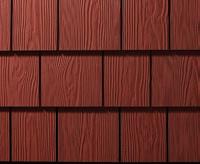
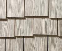
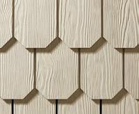
• Available in Straight Edge and Staggered Edge
• Traditional Cedar texture
• Available in Factory Prefinished & Primed
STAGGERED EDGE
Thickness Dimensions Exposure
5 / 16 " 16" x 48" 7"
STRAIGHT EDGE
Thickness
Exposure 5 / 16 " 16" x 48" 7" 5 / 16 " 12" x 48" 5"
* Check market availability, as products may vary.
Review the general cutting, fastening, and wall preparation instructions in Sections 1 through 6 of this guide.
Allura Shake Select Products are specifically designed to be used in exterior, flat vertical wall applications.
Before you install Allura Shake Select products, review and comply with all local building codes and regulations regarding wall construction. Establishing a structural fastening surface sufficient to meet the requirements outlined in this manual is the responsibility of the property owner, architect/designer, general contractor and/ or installer. All Allura Shake products must be installed over structural rated wood sheathing (Minimum 7/16-in. OSB) with framing spaced no greater than 24-in. OC.
Fasteners may or may not hit framing/stud locations. Design the wall assembly to ensure that all appropriate wind load and anchoring requirements are met. Consult the latest version of the QAI Code Evaluation Report CERus-1012 for guidance on approved fasteners.
Starter Strip and Starter Course
To install Allura Shake Select products you must use a starter strip and a starter course. When installing Allura Shake Select products starting at the base of the structure, snap a level chalk line 1-in. above the lowest edge of the sheathing. When installing above a horizontal band board with z flashing, snap a level chalk line at 2-in. Rip a 1-1/2-in. piece of Allura Lap Siding for the starter strip. Align the top of the starter strip with the chalk line and fasten every 12-in. - 16-in OC.
Next install a starter course of 8-1/4-in. Allura Lap siding with the bottom edge 1/4in. below the starter strip, placing fasteners 1-in. below top edge and into framing. This course ensures that the keyways are fully backed by fiber cement on the first course of Allura Shake.
If you are transitioning from less than 8-1/4-in. Allura Lap siding to Allura Shake siding, use 8-1/4-in. lap siding as your starter course at that transition.
DATE: 2021/11/26
REVISION:
WEATHER RESISTANT BARRIER
EXTERIOR SHEATHING
ALLURA SHAKE
ALLURA LAP SIDING
ALLURA SHAKE PANEL
WEATHER RESISTANT BARRIER
EXTERIOR SHEATHING
ALLURA STARTER STRIP STARTER COURSE
Shake Select Square Straight Edge and Staggered Edge panels are produced in three different panels. Each of these panels has a distinct pattern and is identified by the number of V-notches cut into the side of the panel, as shown in the detail below.

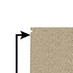
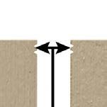
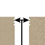
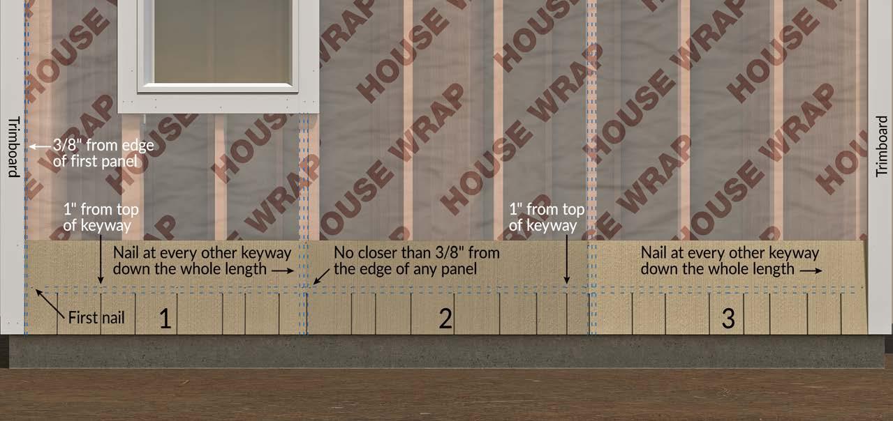
Starting with a panel identified as pattern 1, create a square edge by trimming the top half of the side edge on the left of the panel. Install this panel starting on the left side of the wall. Fasten panel locating fasteners 3/8 inch from the side edges of the panel and 1 inch above the top of the keyway. Fasten at both ends and above every other keyway into structural sheathing. All panels will be fastened following this pattern.
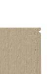
Complete the first course of siding by matching the corresponding v notches and working to the right. Trim the last piece to fit at the termination on the right side of the wall being sure to maintain required clearance. Save the remaining piece to be used later as fill in pieces of left side of wall.
Measure up from the top edge of the panel the same measurement as the exposure of the panel (ex. 7-in. for Shake staggered edge). Make a mark on the wall and use this as your guide to install next course of siding at the proper exposure. Repeat this step for additional courses.
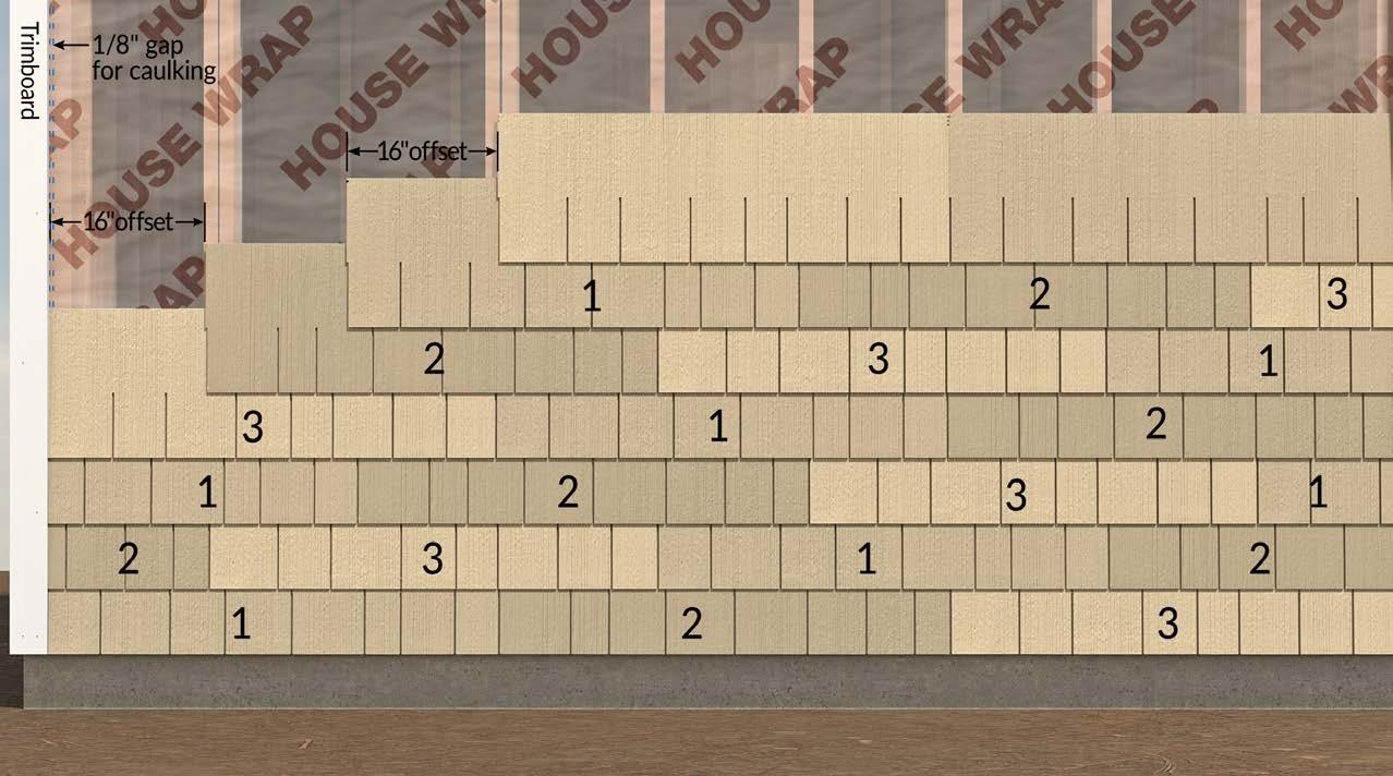
To ensure a random pattern, begin the second course on the left side of the wall using panel pattern 3. The left side of this panel will be installed with a 16-in. offset from the left side of panel 1 in the first course.
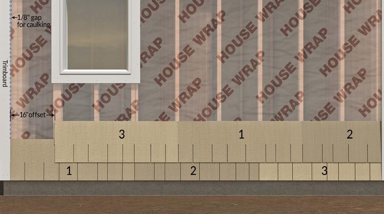
Complete the second course of siding by matching corresponding v notches and working to the right. Again, save the remaining end cut for future use.
To install the third course measure sixteen inches from the left side of pattern 3 and install panel pattern 2.
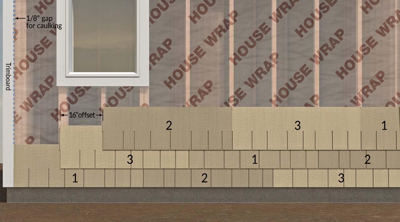
Proceed from left to right to complete course matching corresponding v notches as done in previous course.
The fourth course will begin with a sixteen-inch offset and start with a panel identified as pattern 1.
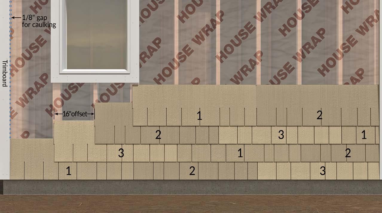
Proceed to finish this course from left to right as in previous courses. Remember to always save cut off pieces from last panel on right to be used as fillers later.
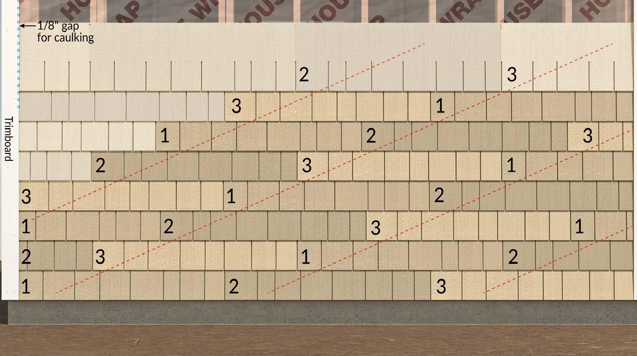
For subsequent courses repeat the 16-in. offset using panels in the same order (3, 2, 1) to complete stairstep pattern up the wall. (See detail below)
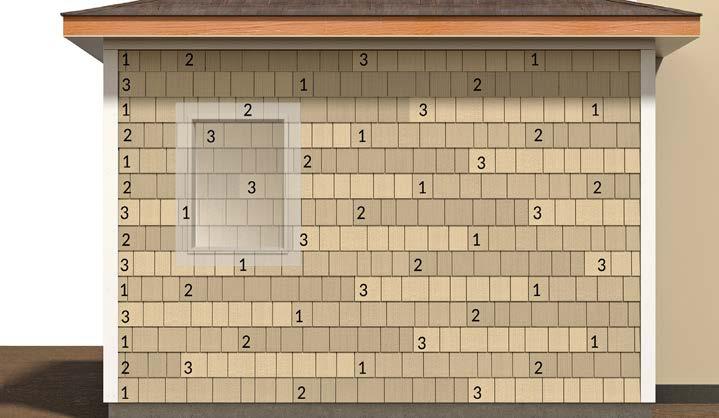
When a window or doorway breaks a course, continue the application as if the opening were not there to ensure the random shake look is maintained.
For all Allura Select products, use minimum 5/4 (1-in.) thick trim.
Once right side is complete, backfill courses from right to left matching v-notches. Use cut off end pieces to fill in last panels at left side trim.
3 2 1 1 3

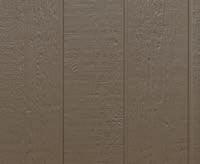
AVAILABLE TEXTURES *
5 / 16 " 4' 8' 5 / 16 " 4' 9' 5 / 16 " 4' 10’
* Check market availability, as products may vary.
Review the general cutting, fastening, and wall preparation instructions in Sections 1 through 6 of this guide.
Allura Panel is specifically designed to be used in exterior, flat vertical wall applications.
Before you install Allura Panel products, review and comply with all local building codes and regulations regarding wall construction. Establishing a structural fastening surface sufficient to meet the requirements outlined in this manual is the responsibility of the property owner, architect/designer, general contractor and/or installer. Design the wall assembly to ensure that all appropriate wind load and anchoring requirements are met. Consult the latest version of the QAI Code Evaluation Report CERus-1012 for guidance on approved fasteners.
To begin the Allura Panel layout, locate the lowest point of the sheathing or sill plate on the walls where Allura Panel is to be installed. Once located, measure up the wall from this point to the floor line break. Make a mark at the floor break and snap a level chalk line across the wall. This line will be a guide for level alignment of the top edge of the Allura Panel.
Do not bridge floors with Allura Panel. You must create a horizontal joint between floors.
For the most symmetrical looking wall, plan for one of the following:
• Center a full panel on the wall or gable with equalsize panels cut for each end
• Join 2 panels on either side of the wall center, leaving equal-size panels on each end.
Vertical edges of Allura Panel must center over studs, so these options may require a centered framing layout.

First Course Installation
Measure and cut the first Allura Panel so that the vertical edges are centered on studs, the bottom edge extends ¼-in. below the lowest point of the sheathing or sill plate and the top edge is aligned with the chalk line. Seal cut edges with Allura Spectrum touch-up or primer.
Once the Allura Panel is set in place, fasten the panel to framing members on all edges and intermediate framing using appropriate fasteners and fastener spacing selected from the CERus-1012. Position fasteners 3/8-in. from panel edges and no closer than 2-in. away from corners. Refer to the CERus before beginning any project.
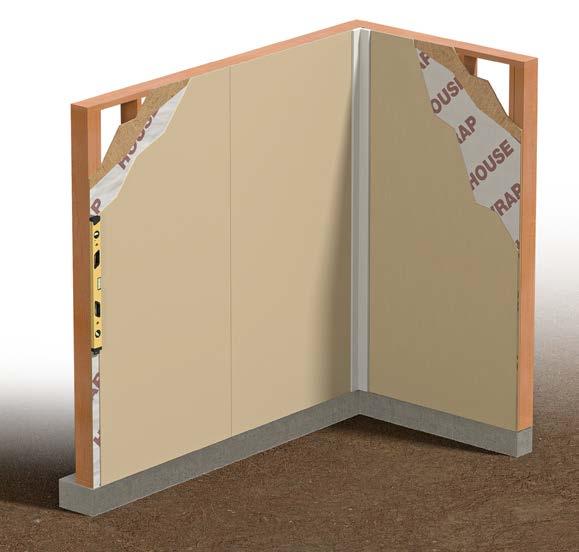
TIP: It is common practice to mark panels for cutting with a chalk line. Blue chalk is recommended because it washes off. Red chalk is considered permanent and may bleed through lighter colored paints.
Continue installing the Allura Panels across the wall to complete the first course. Check the vertical edge with a level as you go.
NOTE: Additional framing or blocking may be necessary for proper attachment. Allura recommends a double stud at butt joints for an easier installation.
When joining the vertical edges of Allura Panel, use one of the options listed below.
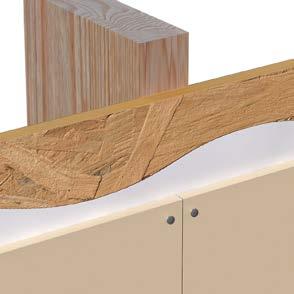
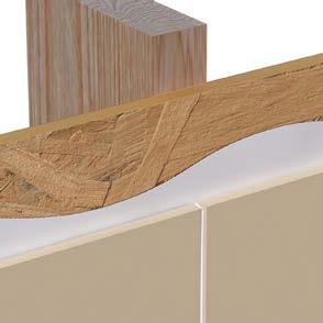
1/8" gap left between panels is filled with caulk (not applicable with Spectrum.)
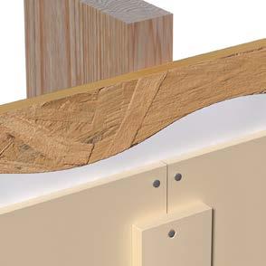
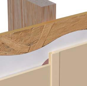
• Lightly butted together with moderate contact
• Appropriate gap between panels and caulked
• Caulked joint covered with a batten strip
• H Channel Joint (Do not caulk)
• Allura recommends the following applications when installing panels with an Allura Spectrum finish:
• Exposed fasteners or battens. Allura does not recommend the caulk joint method when joining panels.
•
•
• Do not use Allura Spectrum touch-up over fastener heads for smooth Allura products
• It is acceptable to use Allura Spectrum touch-up over fasteners for Traditional Cedar or 8-in. OC panel textures only, but correct touch-up application is important. Some colors may show touch-up when applied over fasteners. Trim is recommended to cover joints when appropriate.
In some applications such as multi-story structures or at gable ends, it may be necessary to stack courses of Allura Panel. When this is necessary, you must install z-flashing at the top of every horizontal panel edge before installing the next course. The z-flashing must slope away from the wall, with a ¼-in. gap maintained between the flashing and the bottom of the panel in the next course. It is never acceptable to caulk this gap. Treat horizontal panel joints by using one of the following methods:
When cutting and installing Allura Panel around windows doors and other penetrations be sure to follow all flashing, caulking and clearance requirements.
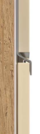
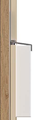
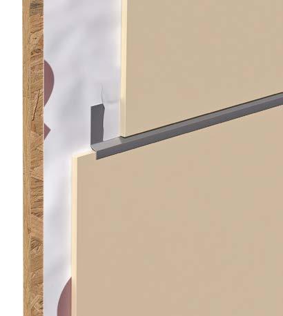
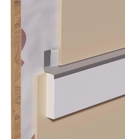
Don't caulk gap between
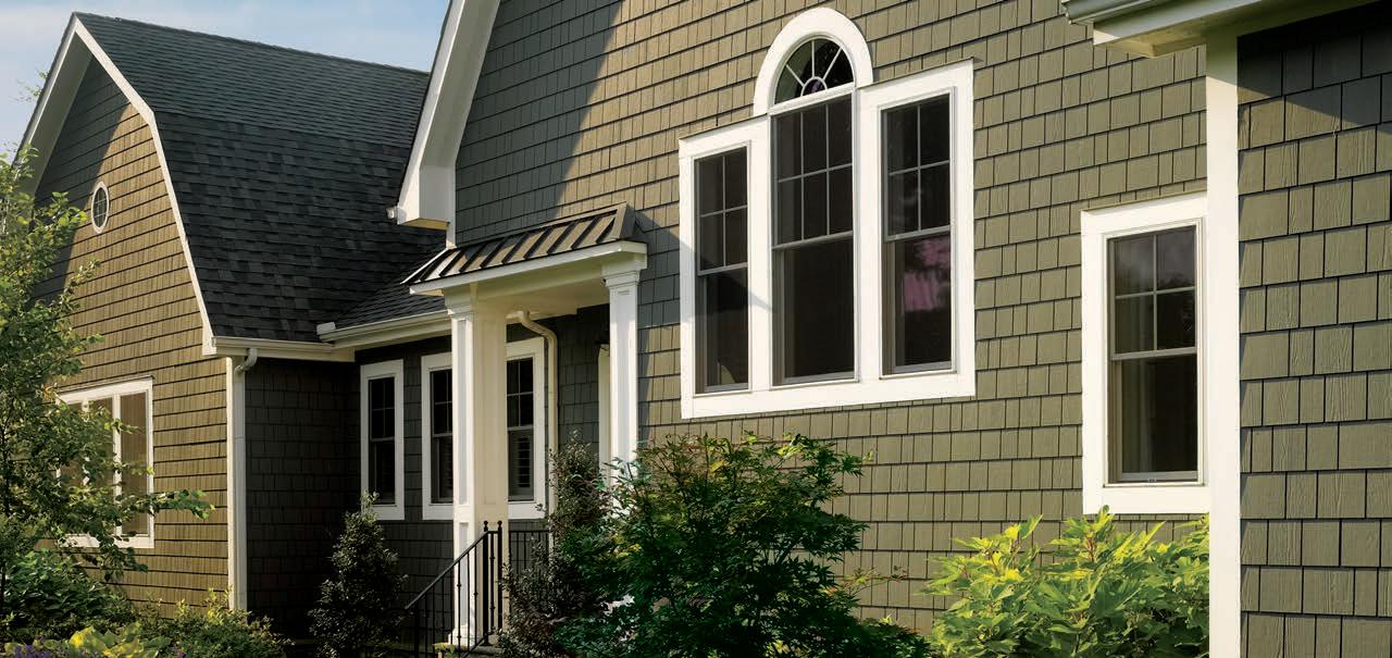
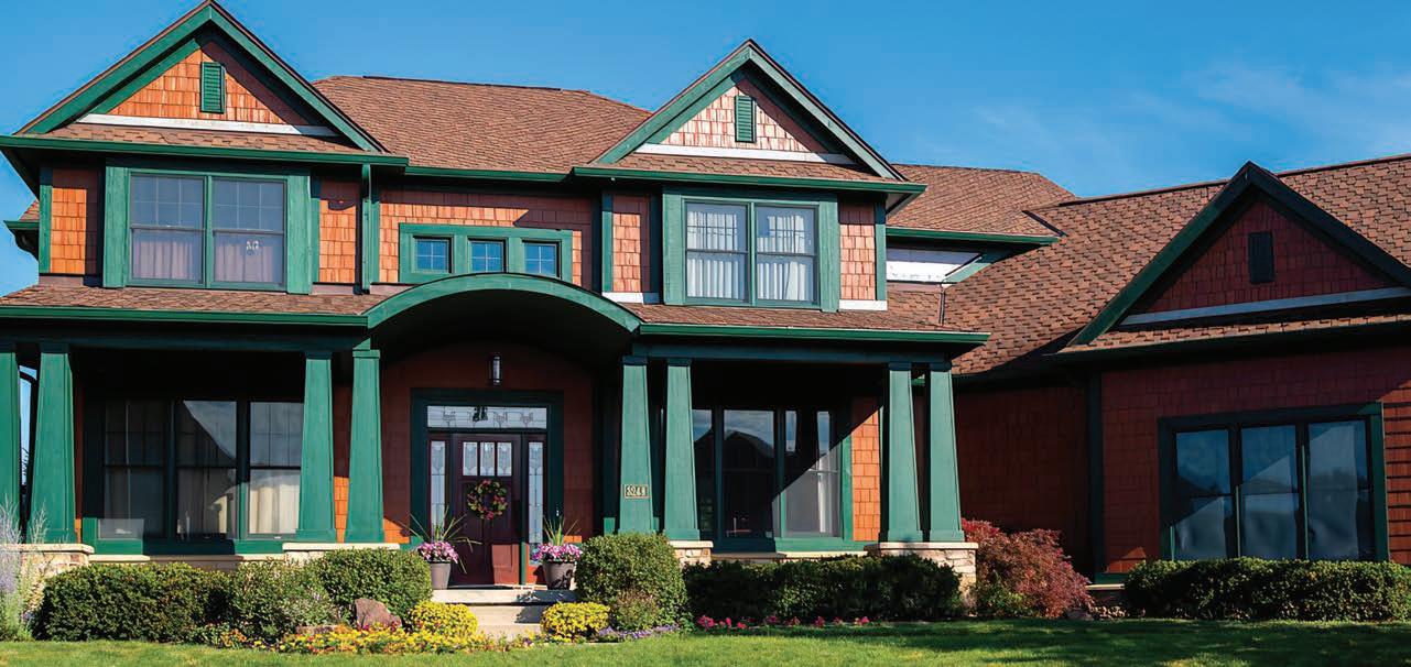
As a low-maintenance alternative to wood, Allura o ers a broad lineup of profiles, decorative siding, shakes, soffits and trims. Historically accurate wide board and batten, wide profiles and vertical panels create attractive architectural designs.
Safe & Durable
Allura has a Class A (1) flame spread rating, will not rot, resists UV rays, and is impervious to wood-boring insects. Our proprietary primer/sealer ensures better weather-resistance by sealing out harmful moisture.
Preferred by Pros
Professionals have come to rely on Allura’s outstanding customer service, on-hand inventory capabilities, and premium quality products.