
Digital Indicator Measurement System
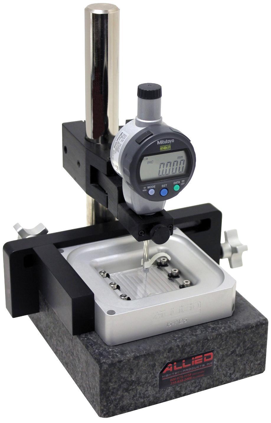
#120-30015 and #15-9120 (shown)
Items Included
The Digital Measurement System can be purchased on its own (#120-30015), or as a kit (#15-9120; shown on cover) that includes the X-Prep® fixture reference assembly. The following items are included in the box to assemble the Digital Indicator Measurement System:




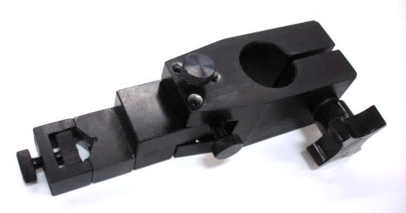
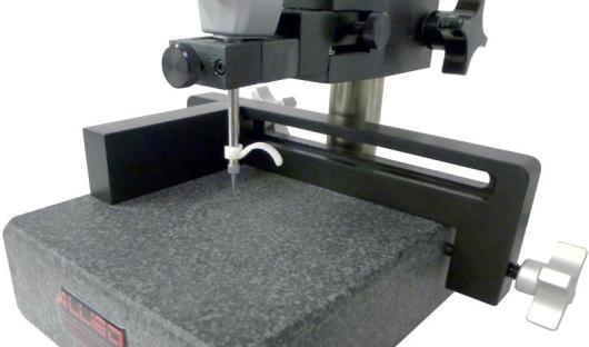
Included with Both #120-30015 and #15-9120 Included with #15-9120 Only
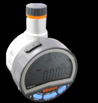
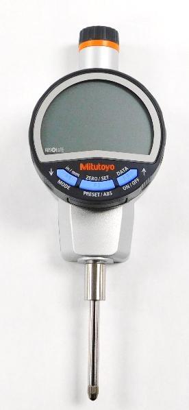
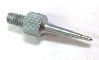
1 Digital Indicator, with Ball Point Contact Tip 7 Needle Point Indicator Tip
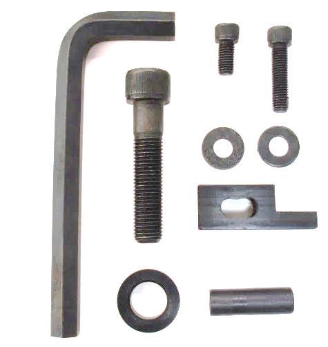
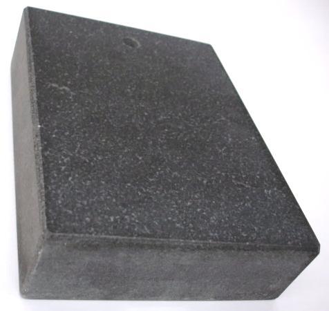
2 Allen Tool, Screws, Washers, & Other Pieces 8 X-Prep® Fixture Reference Assembly 3 Granite Base
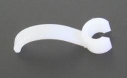
Spindle Lifting Lever
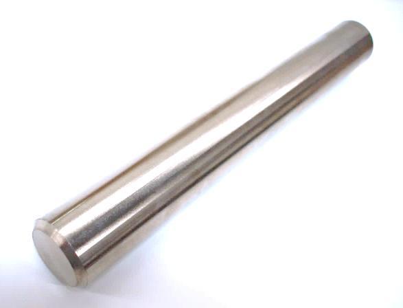
Steel Post 6 Mounting Bracket
Assembly
Before assembling the Digital Indicator Measurement System, wipe off any grease from the various parts. A mild soap and water with a soft cloth can be used to clean these pieces. Make sure each part is completely dry before assembling.
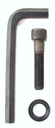
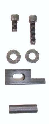
The large screw, large washer, and Allen tool (Figure 1, left) will be used for the general assembly. The other screws, washers, and various parts (Figure 1, right) are only necessary if an indicator with a lug-on mount is used with this system.
For information on installing the locating bracket, please see the Accessories section.
Instructions
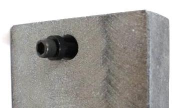
1) Place the large washer around the large screw and insert the screw into the bottom of the granite base (Figure 2).
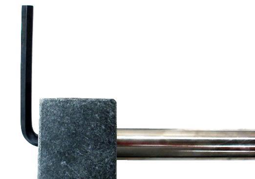
2) Place the steel post on top of the granite base over the screw hole and use the Allen tool to attach the post to the base with the large screw (Figure 3).
3) Loosen the large thumb screw on the mounting bracket and slide the bracket onto the post. Tighten the large thumb screw to secure it to the post (Figure 4). This large thumb screw can also be loosened during operation to adjust the height of the mounting bracket for specimens of different heights and profiles.
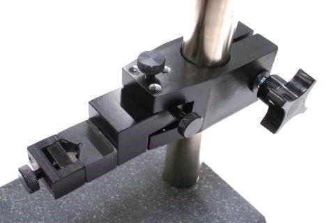
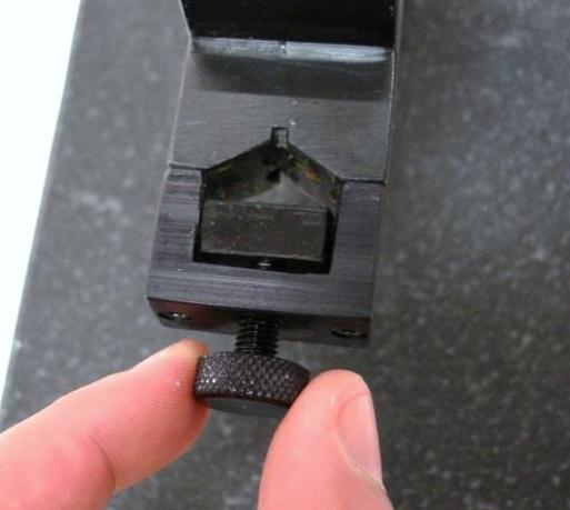
4) Loosen the small thumb screw at the front of the mounting bracket (Figure 5) and insert the digital indicator into the opening. Tighten the small thumb screw to secure the indicator (Figure 6).
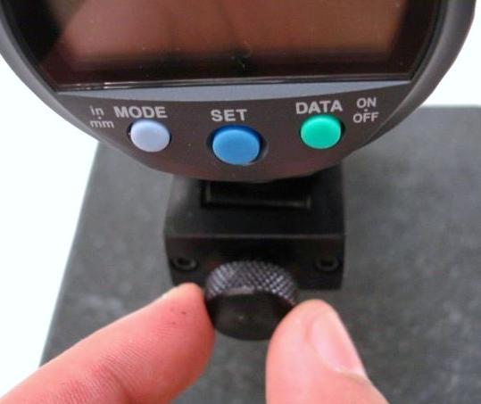
5) The Digital Indicator Measurement System is now fully assembled and ready for measuring heights, thicknesses, and material removal progress, among other metrics.
Using the Digital Indicator
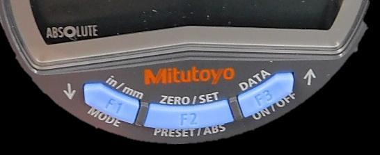
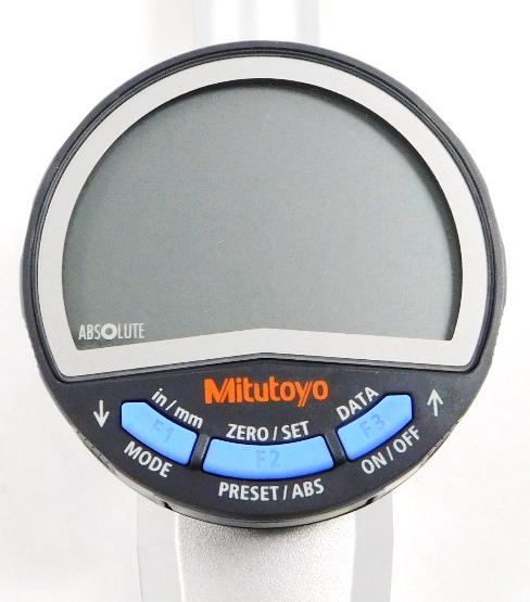
The functions of the three (3) buttons on each digital indicator (Figure 7) are as follows:
1 Push and release to switch between inches and mm.
2 Push and release to zero the display. Push and hold for more than 2 seconds to enter ABS mode, where preset values can be set for the indicator.
3 If the indicator power is off, push and release this button to turn the indicator on. Push and release to “hold” the value on the display. Push and hold for more than 2 seconds to turn the indicator power off.

Accessories
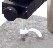
A white, plastic spindle lifting lever is included with the Digital Indicator Measurement System. It can be used to assist in lifting the spindle during measurements without touching the spindle. It allows for more precise movements of the spindle than can be achieved with a hand or fingers; it clips directly onto the spindle (Figure 8), and its position can be adjusted for ease of use.
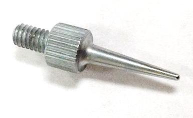
A needle point indicator tip is available for purchase from Allied using item number 120-30015FT. This item is included with the purchase of the #15-9120 Digital Indicator Measurement System. The ball point tip that is pre-installed on the indicator spindle can be unscrewed and replaced with the fine point tip to achieve more accurate measurements within smaller measurement regions. Contact Allied for information about other types of contact tips.
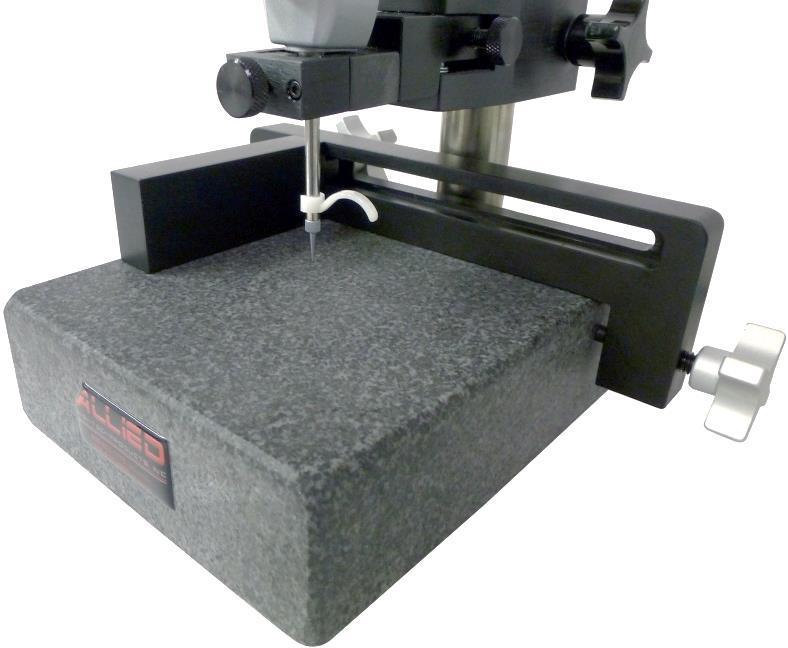
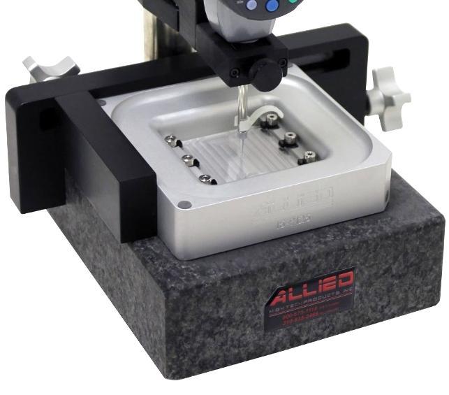
A locating bracket is available for purchase from Allied using item number 120-30015-B. This item is included with the purchase of the #15-9120 Digital Indicator Measurement System (shown on cover). It features an indexing piece that slides across and locks in place for referencing the fixture or specimen in the same spot for every measurement.
This will provide more consistent measurements from step to step of a preparation process, and it is especially useful for samples that are not parallel with the plane of the fixture (such as for samples that have been tilt corrected or contoured using Allied’s X-Prep®).
To install the locating bracket, loosen the large thumbscrew on the longer piece of the bracket (Figure 13, red circle) and slide the bracket onto the granite block. Tighten the thumbscrew to secure the locating bracket in place. Use the second large thumbscrew on the shorter piece of the bracket (Figure 13, green circle) to slide and secure the indexing piece as necessary.
Spare Parts List