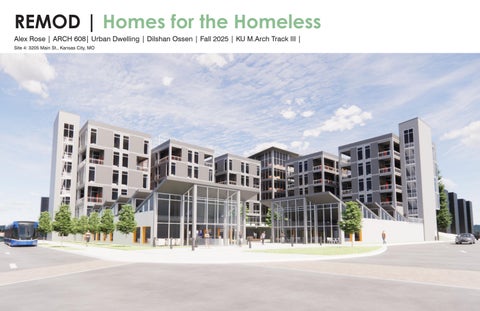
REMOD | Homes for the Homeless Alex Rose | ARCH 608| Urban Dwelling | Dilshan Ossen | Fall 2025 | KU M.Arch Track III | Site 4: 3205 Main St., Kansas City, MO
Community Overview Homelessness is defined as the lack of a fixed, regular, and adequate nighttime residence. In Kansas City, homelessness is concentrated in Midtown and Downtown, particularly near Main Street and Linwood Boulevard. In 2024, the Greater Kansas City Coalition to End Homelessness (GKCCEH) recorded over 2,200 individuals experiencing homelessness on any given night, with 95.7% of chronically homeless individuals unsheltered. The Kansas City Public Schools (KCPS) identified approximately 1,200 youth as unhoused during the school year.
Key Aspects Health Disparities Infrastructure gaps Housing challenges Educational Barriers Economic Disadvantages
Living - wage needed for KC Metro Area
$26.0 4
$32.6 0
$31.40
$37.6 0 Federal Poverty level for a family of 3 = $9.99 2020 Missouri Minimum Wage = $7.85
$16.0 2
Single Adult
1.2 - User Analysis
“I need help with my the IRS and getting my stimulus check. I don’t have an address, so I didn’t get mine when everyone else did.”
“The women’s shelter is not handicap accessible. The shower’s are upstairs, so I can not stay there.” “I need a year - round shelter with minimal entry restrictions (pets, partners, IDs, sobriety).”
2018 Kansas Minimum Wage = $7.25
1 Parent - 1
1 Parent - 2
2 Parent - 1
2 Parent - 2
SC 5.2 User Requirements
Socioeconomic Assessment - Kansas City, MO Education: 40.3% have a bachelor’s degree or higher Average Hourly Wage: $30.78 Average Income: $49,122 Median Household Income: $65,225 Median Gross Rent: $1,215 Homeownership Rate: 56.4% Unemployment Rate: 4.2% as of June 2025 Poverty rate: 13% All images from the Landscape Analysis of Homelessness in the Greater Kansas City
1.2 - User Analysis
SC 5.2 User Requirements
Needs
Aspirations
Challenges
“I need help with my the IRS and getting my stimulus check. I don’t have an address, so I didn’t get mine when everyone else did.” - Julia, 45, Hispanic female
“Year-round shelter with minimal entry restrictions (pets, partners, IDs, sobriety).”- Brian, 30, Black male
“I worked my whole life. Now I am retired, I get a social security check, but it is only enough to afford food or housing. If I wanted to eat, I did not have enough to pay my rent, so I had to come here (the homeless shelter)” Bruce, 69, White male
“What this city needs is help for people to start businesses, kick starters”Gabby, 19, Black female “Food, hygiene, healthcare, and mental health access”- Ruby, 22, NonBinary
1.2 - User Analysis
“In five years, I’ll be in a house, I guarantee it. I believe in the American Dream. You have to work for it. Nothing will fall on your lap. At some point, I will open a food truck.” - Pele, 49, Hispanic male “I can’t work because I am blind. Without work, it is hard to find a place to live. When I get my life together, I want to get married and have a house with a dog.”- Sharon, 40, White female
“Nothing is keeping me from working. My biggest problem is I can’t get to where the work is. Most jobs are out of range for me. The bus routes are inadequate”- Jett, 46, White male “Lack of affordable housing and housing in general.”- Daniel, 55, White male
SC 5.2 User Requirements
Data Collection Homeless population in Missouri
Concerns of the public: “The women’s shelter is not handicap accessible. The shower’s are upstairs, so to stay there, a resident must be able to climb the stairs.”- Karen, 53 ,Black female “Mental health care is almost always either inadequate or unobtainable for people with low or no income.”- Jackie, 23, Black female
“I have bad handwriting, so it is hard to fill in applications. Most want you to fill in applications on a computer, but I do not have a computer.”- Benji, 50 White male
“My wife died, I suffer from severe depression now I am homeless.”- Baker, 50, White male
“I had a felony a few years back and I don’t qualify for Medicaid or food stamps because of it.” - Marshall, 43, Black male
1.2 - User Analysis
“My main problem is work. I lost my house because I lost my job. I can’t get a new house because I can’t get a job.”- Hector, 50, Hispanic male
SC 5.2 User Requirements
The Bridge - Building Scale - Welcome and Dining Building WELCOME BUILDING
The Bridge - Justified Graph - Facility Scale
DINING BUILDING PARK AVE.
CORSICANA ST.
PUBLIC
ENTRY COURT
NON-RESIDENT DINING
ENTRY COURT
PARKING
RECEPTION COMMONS AREA
SECRET GARDEN
SEMIPUBLIC
WOMEN’S SERVICES
LIBRARY SEMIPRIVATE
SECRET GARDEN
WOMEN’S SERVICES
SECRET GARDEN
ENTRY COURT
SHOWERS/ TOILETS
RECEPTION COMMONS AREA
LIBRARY
WELCOME BUILDING
SECURITY/ STORAGE/ KENNELS SEMIPRIVATE
SEMIPRIVATE
CASE OFFICES
PERSONAL CARE
SEMIPUBLIC
SEMIPUBLIC
RESIDENT DINING
PERSONAL CARE
PUBLIC
PUBLIC
SERVICES BUILDING
RESIDENT COURTYARD
DINING BUILDING
MAIN COURTYARD
STORAGE
CASE OFFICES
KITCHEN
PRIVATE
MECHANICAL
EXISTING WAREHOUSE CONVERTED TO SLEEPING PAVILION
PRIVATE
NON-RESIDENT DINING
-
-
The Welcome Building functions as the gateway, filtering visitors into semi-public support services.
RESIDENT DINING
-
Streets = public edge, but once inside, courtyards and dining are semi-private, not fully public.
-
In the Dining Building, non-resident dining = public, while resident dining = semi-public.
-
Courtyards act as defensible semi-private territories — collectively owned but controlled.
-
Most integrated = courtyards/dining (social hubs); most segregated = sleeping pavilion (protection).
-
Kitchen and mechanical zones are most segregated, emphasizing staff-only privacy.
-
Reflects a balance of accessibility and security: thresholds regulate privacy across scales.
-
Thresholds here reinforce Newman’s defensible space: open access for services, but controlled entry to residential life.
SHOWERS TOILETS
MECHANICAL
KITCHEN STORAGE
Personal Care and Women’s Services create semi-private dignity spaces, balancing openness and protection.
The Bridge - Justified Graph - Housing Scale
The Bridge - Building Scale - Services Building -
Ground floor programs (training, mental/physical health) are highly integrated, supporting frequent social use.
-
Upper floors (live/work housing) are more segregated, protecting privacy and resident territoriality.
-
Circulation via lobby/stairs establishes a clear defensible threshold between public and resident spaces.
-
This layering reflects Altman’s boundary regulation: users can choose levels of proximity to others.
WOMEN LIVE/WORK
RESIDENT COURTYARD
1ST FLOOR LOBBY
CORSICANA ST.
LOBBY
STAIRS/ ELEVATORS/ CIRCULATION
TRAINING
PHYSICAL HEALTH
MENTAL HEALTH
ADMINISTRATION OFFICES
SERVICES
ADMINISTRATION
SEMIPRIVATE INTERIM HOUSING WOMEN
SERVICES
1.3 - Case Studies
SERVICES
RESIDENT BEDROOMS (SHARED)
BATHROOM/ SHOWERS
SEMIPUBLIC
SEMIPUBLIC
ADMINISTRATION
INTERIM HOUSING MEN
SECOND FLOOR
DAYROOMS/ LOUNGES
SPECIAL NEEDS HOUSING
2ND FLOOR LOBBY
PHYSICAL HEALTH
SPECIAL NEEDS HOUSING
FIRST FLOOR
PUBLIC
SEMIPRIVATE INTERIM HOUSING WOMEN
LOBBY
PUBLIC
MEN LIVE/WORK
TRAINING
MENTAL HEALTH
SERVICE BUILDING (2F & 3F) LOBBY/ CIRCULATION
CORSICANA ST.
PRIVATE
THIRD FLOOR
INTERIM HOUSING MEN
SPECIAL NEEDS HOUSING
WOMEN LIVE/WORK
MEN LIVE/WORK
INDIVIDUAL SLEEPING ZONES
PRIVATE
-
Housing levels filter access vertically: lobby > lounges > shared bedrooms > special needs/interim housing > bed/personal zone.
-
Bathrooms/showers act as transitional semi-private zones.
-
Gender-specific wings and special needs housing reflect territorial divisions for safety and dignity.
-
Most integrated = lobbies/dayrooms; most segregated = individual sleeping zones.
-
Altman: residents negotiate privacy daily through shared but bounded housing clusters.
PRIVATE
SECOND FLOOR
THIRD FLOOR
SC 5.2 User Requirements
Star Apartments - Justified Graph - Facility Scale
Star Apartments - Justified Graph - Individual Unit
1
MAIN ENTRANCE
2
LOBBY
3
HEALTH CLINIC
4
HOUSING FOR HEALTH OFFICES
5
PARKING
6
PATIO
7
EXERCISE
8
DINING/KITCHEN
9
LIBRARY
10
ART
11
GARDEN
12
APARTMENT
(5) PARKING
PUBLIC
STREET
4
CORRIDOR
PUBLIC 2
1
5
ENTRY/ KITCHENETTE
3
SEMIPUBLIC GROUND LEVEL
SEMIPRIVATE
LIVING AREA
10
(3) HEALTH CLINIC
(4) HOUSING FOR HEALTH OFFICES
INNER CIRCULATION/ STAIRS
BATHROOM
SEMIPUBLIC
MAPLE ST 5TH ST CIRCULATION/ CIRCULATION/ STAIRS STAIRS
9
(8) DINING/ KITCHEN
8
SLEEPING
(1) MAIN ENTRANCE
(2) LOBBY
PRIVATE
(6) PATIO
SEMIPRIVATE
6 7 11
-
Civic functions at ground level (health clinic, retail) = integrated, public-facing spaces.
-
Circulation and patios = semi-public mediators, where chance encounters occur.
-
Modular units = most segregated, providing strong territorial control.
-
Altman: residents choose between solitary retreat or group interaction.
-
Newman: defensible thresholds exist through controlled corridors and shared amenities.
PODIUM LEVEL
12 12
-
Corridor > Entry > Living > Sleeping/Bathroom: a sequential progression of thresholds from shared circulation to personal retreat.
-
Privacy: Residents regulate access at the entry threshold, reinforcing Altman’s concept of boundary control.
-
Territoriality: Each unit is fully self-contained, with lockable doors, kitchen, and bathroom, ensuring strong personal ownership.
-
Defensible Space (Newman): The entry acts as a defensible threshold, clearly separating public circulation from private life.
12 12
12
-
Crowding Relief: Individual kitchens and bathrooms reduce reliance on communal facilities, enhancing dignity and minimizing conflict.
-
Integration vs. Segregation: Most integrated = entry/kitchenette; most segregated = sleeping/bathroom, showing strong privacy depth.
Star Apartments - Justified Graph - Cluster/Vertical Community Scale 1
STREET-LEVEL RETAIL
2
COMMUNITY PROGRAMS
3
VERTICAL CIRCULATION
4
TERRACED CONCRETE SLAB
5
MODULAR UNITS
6
OPEN-AIR CORRIDORS
-
The project works as a vertical neighborhood: retail> community programs > terraces > corridors > units.
-
Open-air corridors = semi-private collective thresholds, not fully public.
-
Modular apartments = private territories, emphasizing resident control.
-
Supports Altman’s model of flexible privacy boundaries and Newman’s idea of segregated safe zones within dense housing.
STREET
PUBLIC
(1) STREET-LEVEL RETAIL
SEMIPUBLIC
(2) COMMUNITY PROGRAMS
(4) TERRACED CONCRETE SLAB
(3) VERTICAL CIRCULATION
SEMIPRIVATE
(6) OPEN-AIR CORRIDORS
(5) MODULAR UNITS
1.3 - Case Studies
PRIVATE
(11) GARDEN
(7) EXERCISE
(9) LIBRARY
(10) ART
(12) APARTMENT
PRIVATE
FOURTH LEVEL
Conclusion - Comparative Analysis
The Bridge Pros - Clear progression of public > private thresholds supports dignity in recovery. - Semi-private courtyards and dining reinforce collective ownership (Newman: defensible space). - Services and personal care facilities allow boundary regulation (Altman) for gradual reintegration. Cons - Dormitory housing risks crowding and limited personal control. - Strong staff/admin oversight may reduce resident autonomy.
Star Apartments Pros - Vertical neighborhood model integrates housing with civic amenities. - Modular units ensure high territorial control and personal privacy. - Semi-public terraces and corridors encourage flexible interaction choices (Altman). Cons - Open-air corridors risk noise and exposure for nearby units. - Vertical circulation can limit accessibility for the wider community.
Lessons Learned The Bridge - excels at creating layered thresholds for dignity, but communal housing limits autonomy. Star Apartments - excels at privacy and territorial control, but risks isolating residents vertically. A resilient urban dwelling model might combine both: Layered thresholds (Bridge) Modular privacy and territorial control (Star) Housing that balances community engagement with individual dignity. Both case studies demonstrate how design mediates privacy, personal space, and territoriality, while circulation patterns shape integration and segregation of residents within the community.
SC 5.2 User Requirements
Site Context: Land Use
Building Context
Building Context
Brownfields/abandoned/underutilized lands
Building Age: Mid to Late 1980s - 2000s Building Materials: -Brick and Mortar -Stone -Glass -Concrete
1.4 - Site & Urban Analysis
SC 5.4 Site Conditions
50’
Building Context: Heights 9.5’
106’
50’
106’
SITE 4
9.5’ 267.5’
40’
75’ 106’
106’ 75’
267.7’
106’
128.38’
106’ 128.38’
9.5’
SITE 4
Setback (25’ min.)
267.7’
9.5’
40’
Setback (25’ min.)
267.5’
Building Context: Use Walking Path Walking Path
Tram Track
Summer Wind Summer Wind
Winter Wind
Tram Track
Winter Wind
BusStop Stop Bus
Existing Vegetation
Existing Vegetation
Lot Dimension ##’##’Lot Dimension Desireable View Desireable View
(ROW) (ROW) ##’##’Right-of-Way Right-of-Way Dimensions Dimensions Parcel Boundaries
Disruptive Noise
Disruptive Noise
Parcel Boundaries
Site 4 Boundaries
Site 4 Boundaries
Setback (25’ min.)
Setback (25’ min.)
1.4 - Site & Urban Analysis
SC 5.4 Site Conditions
Environmental Analysis
1.4 - Site & Urban Analysis
SC 5.4 Site Conditions
Proposed Sites
Site 4: 3205 Main St., Kansas City, MO
Massing Development in the Kansas City Context The massing strategy was shaped using a detailed 3D reconstruction of the site and surrounding blocks in Kansas City, MO. By modeling the neighborhood topography, building heights, transit corridors, and circulation patterns, each massing step could be evaluated against real environmental and urban conditions. This process revealed how solar exposure, prevailing winds, street activity, and adjacent structures influence form, orientation, and courtyard performance. The resulting sequence reflects a design rooted in contextual responsiveness—balancing density, daylight, and community space within an authentic Kansas City urban fabric.
Site 3
Site 2
Site 1
Site 4
t
otte S
d Wyan
e
re Av
o Baltim
E 32
nd S
EL St
oo
t
dB
lvd
W 34
th S
t
n Mai
inw
1.4 - Site & Urban Analysis
SC 5.4 Site Conditions
Concept Statement “Housing as Connected Community”
Design Problem Statement
The design is grounded in the belief that supportive housing must promote dignity, independence, and belonging while responding to the complexities of contemporary urban living. The concept begins with the users—individuals and families seeking stable, affordable homes that balance privacy with opportunities for connection. Their daily routines, comfort needs, cultural practices, and safety concerns directly shape the spatial organization of the project, informing everything from unit layouts to circulation paths and shared amenities.
The project addresses the urgent need for inclusive, affordable urban dwelling solutions that respond to user needs, regulatory requirements, and environmental constraints. The challenge is to create a housing development that balances privacy with community interaction, integrates accessible design principles, and harnesses site-specific environmental opportunities while meeting the spatial requirements of a multistory residential program.
The site, positioned within a dense urban context, becomes an armature for connection. Its edges interface with active streets while the interior massing creates protected communal spaces, encouraging residents to move fluidly between private, semi-private, and public environments. The building’s L-shaped form frames a central open space, enhancing security, visibility, and social cohesion while optimizing natural light, ventilation, and environmental performance. Architecturally, the project synthesizes social, contextual, and ecological factors into a clear structural and spatial system. A rational column-and-slab structure supports modular housing units, promoting construction efficiency and long-term adaptability. Views, daylighting, and cross-ventilation drive the arrangement of living areas and balconies, while shading devices, green roofs, and rainwater management strategies reinforce sustainable performance.
Design Objective - Support user well-being through safe, adaptable, and privacy-conscious unit layouts. - Strengthen community by creating gradients of shared and semi-private spaces oriented around a central courtyard. - Optimize site conditions by shaping massing around daylight, wind, and urban connectivity.
Accessibility and universal design are integral—not additive—components of the concept. Circulation systems, unit layouts, and shared amenity spaces all incorporate ADA principles to ensure equitable use for residents of varying ages and abilities. Safety, comfort, and clarity guide the design of egress paths, corridors, and thresholds throughout the building.
- Integrate ecological systems including green roofs, shading strategies, and rainwater harvesting.
Ultimately, the project positions housing not as a collection of units, but as a layered system of relationships—between residents, between built form and environment, and between the building and its surrounding neighborhood. The design aspires to create a resilient, humane, and connected living environment that supports stability, fosters community, and provides a dignified home for diverse occupants.
- Deliver structural clarity via a repeatable concrete grid system that supports modular housing units.
1.5 - Concept Statement
- Ensure universal accessibility through ADA-compliant circulation, units, and amenity spaces.
- Enhance life-safety performance with intuitive egress routes and clearly organized verti-
SC 5.1 Design Decisions that Synthesized Multiple Factors
Mass Modeling Steps
1.5 - Concept Statement
Step 1 - Define - Establish the full buildable site mass as a starting envelope for program distribution and spatial testing.
Step 2 - Carve - Remove the central volume to introduce a courtyard, improving daylight, ventilation, and community visibility.
Step 3 - Orient - Lift and shape the mass to open sightlines, enhance solar exposure, and strengthen the internal courtyard edge.
Step 4 - Lightwell - Introduce vertical openings to bring natural light deeper into the mass and improve daylight access for interior units.
Step 5 - Balconies - Extend the residential massing with balcony projections to enhance outdoor access, unit livability, and visual connection to the courtyard.
Step 6 - Sawtooth - Introduce sawtooth geometry to optimize sunlight, create rhythmic elevation patterns, and reinforce environmental responsiveness. SC 5.1 Design Decisions that Synthesized Multiple Factors
Zone Planning Overview
INDIVIDUAL UNIT
This diagram illustrates how the facility organizes space across multiple scales—Individual Unit, Cluster, and Block—using a clear public-to-private gradient. By structuring the project with these layered zones, the design supports safety, dignity, daily function, and community interaction while maintaining appropriate levels of privacy for residents.
CORRIDOR
PUBLIC
Individual Unit ENTRY/ KITCHENETTE
The Individual Unit diagram shows the progression from public circulation to the most private residential spaces.
SEMIPUBLIC
- The corridor represents the public interface where staff and residents move throughout the building. - The entry/kitchenette acts as a semi-public threshold, offering a soft transition before entering the resident’s personal space.
LIVING AREA
BALCONY
SEMIPRIVATE
SLEEPING
BATHROOM
PRIVATE
- Living area and balcony are semi-private spaces where residents can socialize, relax, and connect to outdoor views while still maintaining personal control over the space. - Sleeping and bathroom areas are fully private zones, ensuring residents’ comfort, autonomy, and security. This organization reflects a gradual narrowing of access, supporting both functionality and emotional well-being.
BLOCK
Block Scale STREET
The block diagram represents how all buildings and program types relate to each other within the larger site. Street and public services buildings form the public edge, supporting neighborhood connections and providing essential civic functions. Semi-public components such as the courtyard and café/market building invite community engagement while still acting as a buffer between the broader public and the residents. Resident parking and the residents’ building introduce semi-private to private layers, limiting access to tenants, staff, and approved visitors.
PUBLIC SERVICES BUILDING
CAFE/MARKET BUILDING
RESIDENT PARKING
COURTYARD
The block-level zoning reinforces safety, accessibility, and community integration while maintaining a coherent privacy gradient across the entire site.
RESIDENTS BUILDING
1.6 - Zone Planning
PUBLIC
SEMIPUBLIC
SEMIPRIVATE
PRIVATE
SC 5.1 Design Decisions that Synthesized Multiple Factors
Cluster Scale
CLUSTER
At the cluster level, individual units connect to shared amenities that foster community, services, and daily activity while still respecting privacy needs.
Shared areas such as the elevator lobby, resident commons, library/study lounge, and coworking/ computer lab fall into the semi-private zone, promoting interaction while remaining accessible primarily to residents and staff. Support spaces (HVAC, janitorial, mechanical, storage) and service-oriented programs like telehealth, case management, counseling, and gym occupy the semi-private to private spectrum, providing residents with essential resources in a safe, managed environment.
STREET
CAFE
The most private areas include therapy rooms, resident units, and gym bathrooms, which require discretion and controlled access. This hierarchy ensures that residents encounter appropriate degrees of community, support, and privacy within their daily routines.
Design Rationale
PUBLIC SERVICES BUILDING
CAFE/MARKET BUILDING
Street, courtyard, and resident parking operate as the public-facing edges of the cluster.
RESIDENT PARKING
PUBLIC
MARKET
PUBLIC RESTROOM
KITCHEN
COURTYARD
JANITOR’S CLOSET
SEMIPUBLIC
STORAGE/ HVAC/ ELECTRICAL
STREET
COURTYARD
RESIDENT PARKING
LOBBY
CORRIDOR
DAYCARE
VOCATIONAL TRAINING
SUPPORTIVE STAFF WAITING ROOM
PUBLIC SEMIRESTROOM PRIVATE
STAFF BREAK ROOM
SUPPORTIVE STAFF OFFICE
PRIVATE
By synthesizing public-to-private relationships at three scales, the project establishes a consistent organizational logic that guides circulation, access, safety, and user experience. This approach: STREET
COURTYARD
RESIDENT PARKING
PUBLIC
ELEVATOR LOBBY
RESIDENT COMMONS
SEMIPUBLIC
Improves wayfinding and operational clarity for staff. Strengthens community engagement while protecting resident privacy.
HVAC/ RESIDENT BIKE MECHANICAL/ STORAGE & ELECTRICAL/ REPAIR JANITORIAL/ETC
TELEHEALTH BOOTH
1.7 Bubble/Block Diagrams
SEMIPUBLIC
SEMIPRIVATE
DAYCARE STORAGE
PRIVATE
RESIDENTS BUILDING
Enhances resident well-being through predictable transitions between social and private spaces.
Creates a flexible framework that can adapt to diverse activities and support services.
DAYCARE RESTROOM
PUBLIC
CORRIDOR/ CIRCULATION
TELEHEALTH/ THERAPY
MAKER STUDIO
CASE MGMT
COUNSELING
CASE MGMT OFFICE
COUNSELING SUITE
COWORK/ COMPUTER LAB
LIBRARY/ STUDY LOUNGE
SEMIPRIVATE
GYM BATHROOM
PRIVATE
GYM
RESIDENT UNIT
SC 5.1 Design Decisions that Synthesized Multiple Factors | SC 5.2 User Requirements
Tree Selection & Placement
Stormwater Reduction (2025)
Two Swamp White Oaks (Quercus bicolor) were selected and placed within the central courtyard of the proposed development. This species is widely recommended for Kansas City due to its high heat tolerance, excellent stormwater interception, and long-term carbon sequestration capacity. The courtyard location provides ideal full-sun exposure and positions the trees to offer both microclimate benefits and pedestrian comfort, enhancing the usability of exterior spaces throughout the year.
Current-Year Environmental Benefits (2025)
The two oaks intercept: - 1,479 gallons of rainfall, - Preventing approximately 145 gallons of stormwater runoff at the source. This benefit helps counteract runoff from paved surfaces and supports healthier site hydrology.
Carbon Sequestration (2025) According to i-Tree Design results, the two newly planted oaks provide an estimated: $27 in combined annual environmental benefits, including: - Stormwater interception: 21.50 gallons - Air quality improvements: $1.30 worth of pollutant removal - Carbon sequestration: 4.18 lbs of CO2 absorbed The trees help reduce heat, filter pollutants, and begin establishing shade that will increase as they mature.
This year, the trees will: - Reduce atmospheric CO2 by 364 lbs, - Already stored 2,958 lbs (projected cumulative sequestration estimate). This aligns with long-term carbon reduction initiatives and supports community climate goals. 1.8 Ecological Analysis
SC 5.5 Ecological Concerns and Consider Measurable Environmental Impacts
Future-Year Environmental Benefits (2045)
After 20 years of growth, the two mature oaks are expected to provide: - $63 in annual environmental benefits, consisting of: - 46.14 gallons of stormwater reduction - $3.52 of air quality improvements - 13.21 lbs of CO2 removal annually This represents more than double the annual benefit compared to year one.
Carbon Sequestration (2045)
In 20 years, these oaks will: - Reduce atmospheric CO2 by 782 lbs per year Store a significantly greater cumulative amount over the tree’s lifespan, contributing to long-term carbon reduction goals. Energy-Related Benefits
Stormwater Reduction (2045)
By year 2045, the two oaks will: Intercept 4,021 gallons of rainfall per year, And prevent 394 gallons of stormwater runoff. This makes the courtyard a high-performing green infrastructure zone. 1.8 Ecological Analysis
While detailed shading/energy savings could not be calculated due to mapping limitations, the placement of two large deciduous trees will: - Provide cooling shade to reduce heat island effects in summer - Allow sunlight penetration in winter after leaf drop - Contribute to more comfortable microclimates within the courtyard circulation areas These qualitative benefits support the building’s passive design strategies already shown in the solar analysis section. SC 5.5 Ecological Concerns and Consider Measurable Environmental Impacts
Baseline Condition Summary The existing site is overwhelmingly dominated by impervious surfaces, with approximately 91% impervious coverage (asphalt + rooftops). The remaining 9% consists primarily of narrow lawn strips with minimal ecological function. The dominance of hardscape leads to high runoff, low infiltration, and no integrated green infrastructure.
Baseline Land Cover Table: Category
Area (SF)
% of Site
Impervious (Building + Asphalt)
~50,000 SF
91%
Lawn (Existing Grass Strips)
~4,800 SF
9%
Meadows
0 SF
0%
Forest Desert
0 SF 0 SF
0% 0%
TOTAL
55,105 SF
100%
Baseline Low Impact Development (LID) Features: LID Feature
% of Site
Disconnection Rain Harvesting
0% 0%
Rain Garden
0%
Street Planters
0%
Infiltration Basin Permeable Pavement
0% 0%
iTree Summary The i-Tree Design analysis reinforces the environmental value of integrating large canopy trees into the courtyard. Even with only two Swamp White Oaks, the site realizes measurable gains in stormwater control, carbon sequestration, air quality improvement, and long-term ecological resilience. As the trees mature, their annual benefits more than double, demonstrating how strategic landscape design contributes significantly to sustainability goals and enhances the comfort and performance of the overall development. Only two trees were modeled due to platform limitations, but the selected species and placement represent the intended canopy strategy for full build-out. 1.8 Ecological Analysis
Key Takeaway: Stormwater modeling confirms that runoff at the existing site is excessively high due to impervious coverage and compacted soils. After redesign, the number of fully retained wet days more than doubles, annual runoff is reduced by 21.6%, and both infiltration and evaporation significantly increase. These improvements result directly from the introduction of LID systems—green roofs, permeable paving, street planters, and rain gardens—applied systematically across the development.
SC 5.5 Ecological Concerns and Consider Measurable Environmental Impacts
Baseline Stormwater Performance
AFTER Design Performance
Today, the site receives 35.45 in. of annual rainfall, of which 30.33 in. becomes runoff—an 85.6% runoff rate. Only 14.7% of wet days retain any rainfall at all.
The proposed plan introduces green roofs, permeable paving, rain gardens, street planters, and rainwater harvesting. These interventions dramatically shift site hydrology:
The site’s clay-loam soils already infiltrate slowly, but the larger issue is the site’s asphalt-dominated surface, which prevents water from soaking into the ground.
- Annual runoff decreases from 30.33 in. to 23.79 in. (21.6% reduction)
Baseline Pie Chart Interpretation:
- Fully retained wet days increase from 14.7% to 29.39%
- Runoff (Teal): Overwhelmingly dominant due to nearly continuous asphalt and building roofs.
- Maximum rainfall retained increases from 0.56 in. to 0.78 in.
- Infiltration (Light Green): Severely limited due to soil conditions + impermeable surfaces. - Evaporation (Orange): Minimal because vegetation is sparse and fragmented. Stormwater discharge is extremely high, ecological function is low, and the existing landscape offers no meaningful stormwater retention value.
Proposed Pie Chart Interpretation: - Runoff decreases significantly, reflecting added permeability. - Infiltration increases, supported by vegetated + permeable surfaces. - Evaporation increases, due to the expanded green roof and landscape systems. The redesigned site performs more than twice as well hydrologically, confirming a strong ecological benefit.
1.9 Environmental Analysis | 2.10 Service Drawings
SC 5.5 Ecological Concerns and Consider Measurable Environmental Impacts
Integrated Green Roof + PV System & Stormwater Strategy
Biosolar PV + Sedum Green Roof (Non-Walkable / Utility Roof)
The project combines walkable intensive green roofs with a biosolar PV green-roof system to improve building performance, enhance resident experience, and integrate seamlessly with the rainwater harvesting and cistern network. The concrete structural frame allows for deeper soil profiles, water-storage layers, and non-penetrating PV foundations.
Purpose To increase PV efficiency while providing a lightweight vegetated roof that retains water and cools the roof surface.
Intensive Walkable Green Roof (Amenity Roof) System: ZinCo Roof Garden System with Floradrain® FD 60 neo Purpose A multifunctional rooftop landscape designed for walking, seating, gathering, and small resident garden plots. Layer Functions Vegetation + Deep Growing Medium (8–12”) Supports shrubs, native plants, and small food-garden beds. Filter Sheet Prevents fine particles from clogging drainage layer. Floradrain® FD 60 neo (Water-Retention + Drainage Layer) Stores stormwater, promotes capillary irrigation, and controls overflow to roof drains. Protection Mat + Root Barrier Protects membrane and prevents root penetration. Waterproofing Membrane (Root-Resistant) Primary building envelope protection. Concrete Deck Structural support for amenity use and planters. Benefits - Walkable + furniture-supporting surface - High stormwater retention to reduce potable irrigation demand Enhanced resident comfort and rooftop microclimate Overflow drains feed directly into the 25,000-gallon cistern
System: ZinCo Solarvert System with Solar Base SB 200
Layer Functions - Sedum Vegetation Layer - Low-maintenance cooling and biodiversity support. - Extensive Substrate + Filter Layer - Lightweight soil and sheet assembly for water retention. - Fixodrain® / Drainage Layer - Provides water retention and controlled drainage. - Solar Base SB 200 (Ballasted Mounting) - Holds PV frames using the weight of the green roof—no membrane penetrations. - Root-Resistant Waterproofing + Concrete Deck Benefits - Cooler roof surface increases PV output - No penetrations in roof membrane - Vegetation reduces heat-island effect - Runoff routed to cistern for reuse
System Integration with Rainwater Harvesting Both green roof systems retain water and slow runoff. Controlled overflow directs excess stormwater into the building’s downspout network. Downspouts convey water to the 25,000-gallon below-grade cistern. Stored water is treated and reused for: - Courtyard and landscape irrigation - Green roof supplemental irrigation - Toilet flushing in residential units During major storms, overflow safely connects to the municipal storm main. Summary Together, the intensive amenity roof and biosolar PV roof create a high-performance ecological system: improving energy efficiency, reducing potable water demand, enhancing stormwater management, and providing meaningful outdoor space for residents.
1.9 Environmental Analysis | 2.10 Service Drawings
SC 5.5 Ecological Concerns and Consider Measurable Environmental Impacts
Rainwater Harvesting & Reuse Strategy Roof runoff from the green roofs, sawtooth roofs, and terraces is collected via the building’s downspout network and routed by gravity into a 25,000-gallon below-grade cistern located beneath the east café/market building. Incoming water passes through debris screening and first-flush filtration before entering the tank. Captured rainwater is treated in a pump + filtration room and distributed through a network of non-potable reuse pipes for: - Courtyard irrigation - Landscape plantings - Flushing toilets in residential units During major storm events, a controlled overflow connection routes excess water safely to the municipal storm system. This integrated approach significantly reduces potable water use, supports landscape resilience, and enhances overall site sustainability.
Roof downspouts carrying untreated rainwater vertically Horizontal rainwater collection mains
Altogether, the stormwater model, solar studies, and shading analysis demonstrate a unified environmental strategy that improves ecological function, reduces energy demand, and enhances livability. The design reduces runoff, increases infiltration, optimizes solar and daylight harvesting, and creates comfortable microclimates across the site. These findings verify that the architectural and landscape systems operate holistically to support resilient, low-carbon, and community-centered development.
Non-potable reuse lines supplying toilets FLOW DIRECTION
RAIN RAIN
RAIN
BATH ROOM
BATH ROOM
BATH ROOM
BATH ROOM
NON-POTABLE REUSE
1.9 Environmental Analysis | 2.10 Service Drawings
CISTERN
IN
RA
N
IO
CT
E LL
CO
SC 5.5 Ecological Concerns and Consider Measurable Environmental Impacts
9 AM
Summer Solstice
Sun/Shadow Studies
Winter solar behavior: In winter, the sun sits much lower on the horizon, producing long, extended shadows. During the winter solstice, the café/market building and the east residential massing cast shadows that stretch deeply into the courtyard, especially around midday. Only selective areas of the central lawn receive direct sunlight at this time of year.
Summer Solstice The seasonal sun/shadow studies illustrate how the building massing, sawtooth roof forms, balconies, and courtyard geometry respond to changing solar angles throughout the year. Summer solar behavior: During the summer solstice, the sun reaches a high position in the sky, producing short, compact shadows. Because the majority of the residential massing sits south of the courtyard, these buildings do not obstruct sunlight from entering the central outdoor space. Even the taller residential wings on the east side cast minimal shade at noon— the steep solar angle keeps their shadows tight to the building base.
12 PM
HIGH SUMMER SUN
DEEPER SUNLIGHT
EAST BLDG
SHORT SHADOW 1.9 Environmental Analysis
LOW WINTER SUN
The lower sun angle allows the sawtooth clerestories to capture diffuse northern daylight for interior workspaces while still permitting controlled winter solar gain into key residential areas.
12 PM
Courtyard comfort: While a portion of the courtyard is shaded, the low-angle winter sun still reaches deeper into residential units, improving passive heating potential and reducing winter energy use. Shaded areas of the courtyard remain usable for circulation, seating, and protected outdoor activities—even during colder months.
The courtyard therefore receives abundant direct sunlight during midday, making the outdoor environment bright and active. At the same time, the elevated walkways and overhangs surrounding the courtyard provide cool, shaded pockets for comfort—allowing residents to choose between sun and shade depending on activity and season. Balconies on the south and west façades further enhance summer comfort by providing passive shading to living spaces.
Winter Solstice
9 AM
4 PM
Conclusion The overall seasonal sun/shade patterns confirm that the design successfully leverages solar performance to enhance year-round comfort: Summer: - High sun angle maximizes light in the courtyard - Short shadows keep spaces bright and usable - Overhangs and balconies provide intentional shading for thermal comfort Winter: - Low-angle sun provides passive heating to residential interiors - Longer shadows reduce winter glare and moderate outdoor conditions - Courtyard remains accessible with a balanced mix of sun and shade
4 PM
Together, these strategies optimize daylight, shading, and thermal performance—ensuring that the courtyard and surrounding residential units remain comfortable, adaptable, and energy-responsive throughout the year. SC 5.5 Ecological Concerns and Consider Measurable Environmental Impacts
Photovoltaic Array: The PV system is strategically placed on high-insolation roof zones to maximize annual solar energy production, reducing operational carbon and supporting long-term energy resilience.
Light Wells: Vertical light wells deliver natural daylight deep into unit corridors and living spaces, reducing reliance on electric light and improving visual comfort.
Green Roof System: Green roofs capture rainfall, reduce stormwater runoff, moderate rooftop temperatures, and enhance building insulation while creating beneficial microclimates.
Summer Solstice
Winter Solstice Sawtooth Roof Section The sawtooth roof geometry is optimized for north-facing daylight, which is diffused, glare-free, and ideal for interior workspaces. The south-facing opaque slopes block direct summer solar gain while allowing winter sunlight to enter at a lower angle.
Balconies as Passive Shading: Balcony overhangs minimize high-angle summer solar gain while allowing deeper low-angle winter sunlight penetration—improving thermal comfort and daylight access.
Optimized Window Placement: Windows are oriented and sized to maximize daylighting while supporting cross-ventilation, reducing mechanical loads and enhancing indoor comfort.
This geometry yields: Reduced summer glare + overheating Improved winter heating through passive solar gain Strong daylight availability year-round Enhanced energy efficiency from reduced artificial lighting needs 1.9 Environmental Analysis
SC 5.5 Ecological Concerns and Consider Measurable Environmental Impacts
Solar Analysis - Annual Insolation Study The annual insolation study quantifies how the building form, roof geometry, façade orientation, and shading devices interact with Kansas City’s solar climate. High-exposure roof zones demonstrate excellent potential for renewable energy generation, while moderated façade exposure confirms effective passive design strategies that maintain resident comfort. Strong Solar Exposure on Roof Surfaces The study indicates that all roof surfaces—particularly the large top roof, greenhouse roofs, and sawtooth roofs—receive the highest annual solar insolation. This is ideal for: Photovoltaic panel placement Green roof plant viability Potential seasonal heating benefits Peak roof values approach the upper limits (≈ 1200–1300 kWh/m² annually, depending on color scale), making these surfaces ideal solar harvesting areas.
South and West Facades Perform as Expected The south-facing residential facades show consistently strong solar exposure, validating the design strategy of: Orienting deeper living spaces toward the south Using large window openings to maximize passive daylight Enhancing natural lighting penetration into units—reducing daytime lighting loads The west-facing facades also receive high insolation, emphasizing the importance of controlled shading devices and high-performance glazing.
Balcony Overhangs Are Functioning Correctly The heatmap clearly shows the balconies: Reduce direct solar gain on upper façade zones Permit winter sun to penetrate deeper into living spaces Provide effective passive shading during hotter months Create a comfortable microclimate for residents This confirms that the balcony depth/angle is performing as intended in the environmental strategy.
1.9 Environmental Analysis
SC 5.5 Ecological Concerns and Consider Measurable Environmental Impacts
Thermal + Daylight Synergy in Community Spaces
Design Strengths Confirmed by Solar Study:
The sawtooth roof structures above the community block receive high annual sunlight, reinforcing their purpose as daylight collectors.
The analysis validates several intentional environmental design strategies:
This strongly supports: Even daylight distribution inside coworking and learning spaces
Passive solar design works Deep light penetration into residential units is visible and effective. Shading elements function correctly Balconies + sawtooth geometry moderate excessive solar gain.
Reduced electrical lighting loads Integration of rooftop solar panels + clerestory strategy
Roof PV potential is extremely strong Large, flat surfaces optimize renewable energy harvesting. Courtyard microclimate is comfortable Reduced insolation supports outdoor public programming. Facades are appropriately oriented South and west sides operate according to solar design principles. Overall, the solar performance study verifies that the building massing, façade articulation, and rooftop configurations are well-tuned to Kansas City’s solar climate. High-insolation roof zones support PV and greenhouse programming, while moderated façade exposure ensures resident comfort. The solar and shading strategy operates as an integrated system across architecture, landscape, and program.
1.9 Environmental Analysis
SC 5.5 Ecological Concerns and Consider Measurable Environmental Impacts
E 32ND ST
25’
Telehealth / Therapy Rooms
Case Mgmt Counseling Suite
SET BACK
UP
L2 Janitor / Maintenance / Trash
DN UP
L2 Back Lobby
Maker Studio
MAIN ST
L2 Residents Commons
COURTYARD Co-Work / Computer Lab
Library / Study Lounge
Gym
OOD
LINW 1
SITE PLAN SCALE: 1/16” = 1’-0” 2.1 - SITE PLAN
UP
BLVD
Level 2 Copy 2 1/16" = 1'-0"
0'
8'
16'
32'
64'
SC 5.3 Regulatory Requirements | SC 5.4 Site Conditions
RESIDENT PARKING
HVAC/ MECH./ ELEC./ TRASH
DAYCARE OUTDOOR PLAYGROUND
GF ELEVATOR LOBBY
DAYCARE STORAGE DAYCARE RR
RESIDENT BIKE STORAGE/REPAIR
JANITOR/ STORAGE
VOCATIONAL TRAINING
VOCATIONAL TRAINING
RESIDENT PARKING
SUPPORTIVE STAFF MEN’S RR
WOMEN’S RR
COURTYARD
FAMILY RR LOBBY
MARKET
CAFE
KITCHEN
MEN’S JANIRR TOR
STAFF BREAK
STORAGE/ HVAC/ ELECTRICAL
WOMEN’S RR
GROUND FLOOR SCALE - 1/16” = 1’0” 2.2 - All Floor Plans
0'
8'
16'
32'
64'
SC 5.1 | SC 5.2 | SC 5.3 | SC 5.6 | SC 6.6
UP
DN UP
UP
CASE MGMT
TELEHEATLH/ THERAPY
COUNSELING SUITES
MAKER STUDIO
L2 JANITOR/ MAIN./ TRASH
DN UP
L2 ELEVATOR LOBBY L2 RESIDENTIAL COMMONS
CO-WORK/ COMPUTER LAB
LIBRARY/ STUDY ROOM
UP
GYM
RR
RR
UP
SECOND FLOOR SCALE - 1/16” = 1’0” 2.2 - All Floor Plans
0' 1
Level 2 Copy 2 1/16" = 1'-0"
8'
16'
32'
64'
SC 5.1 | SC 5.2 | SC 5.3 | SC 5.6 | SC 6.6
UP DN
DN UP
UP DN
1 BR
1 BR
2 BR
2 BR
1 BR
1 BR
L3 JANITOR/ MAIN./ TRASH
DN UP
L3 ELEVATOR LOBBY L3 RESIDENTIAL COMMONS
3 BR
1 BR UP DN
1 BR
UP DN
THIRD FLOOR SCALE - 1/16” = 1’0” 2.2 - All Floor Plans
0' 1
Level 3 Copy 1 1/16" = 1'-0"
8'
16'
32'
64'
SC 5.1 | SC 5.2 | SC 5.3 | SC 5.6 | SC 6.6
UP DN
UP DN
2 BR
2 BR
3 BR
2 BR
2 BR
2 BR
2 BR
L4 JANITOR/ MAIN./ TRASH
3 BR
2 BR
L4 Janitor / Maintenance / Trash
2 BR DN UP
DN
L4 ELEVATOR LOBBY
L4 Back Lobby L4 Resident Commons
L4 RESIDENTIAL COMMONS
3 BR
3 BR
1 BR
1 BR
1 BR
1 BR
1
UP
UP
DN
DN
Level 4 Copy 1 1/16" = 1'-0"
FOURTH FLOOR SCALE - 1/16” = 1’0”
0'
2.2 - All Floor Plans
8'
16'
32'
64'
0'
8'
16'
32'
64'
SC 5.1 | SC 5.2 | SC 5.3 | SC 5.6 | SC 6.6 Level 4 Copy 1
UP DN
UP DN
1 BR
1 BR
2 BR
1 BR
2 BR
1 BR
1 BR
2 BR
2 BR
1 BR
L5 JANITOR/ 1 BR MAIN./ TRASH
L5 Janitor / Maintenance / Trash
1 BR
UP
DN UP
L5 Elevator Lobby
L5 ELEVATOR LOBBY
L5 Resident Commons
L5 RESIDENTIAL COMMONS
3 BR
3 BR
1 BR
1 BR
1 BR
1 BR UP
UP
1
Level 5 Copy 1 1/16" = 1'-0"
1
DN
DN
Level 5 Copy 1 1/16" = 1'-0"
FIFTH FLOOR SCALE - 1/16” = 1’0” 2.2 - All Floor Plans
0'
8'
16'
32'
64'
0'
8'
16'
32'
64'
SC 5.1 | SC 5.2 | SC 5.3 | SC 5.6 | SC 6.6
UP DN UP DN
2 BR
2 BR
2 BR
3 BR
2 BR
2 BR
L6 JANITOR/ MAIN./ TRASH
3 BR
2 BR
2 BR
L6 Janitor / Maintenance / Trash
2 BR
Room
UP
DN UP
L6 Elevator Lobby
L6 ELEVATOR LOBBY
L6 Resident Commons
L6 RESIDENTIAL COMMONS
3 BR
3 BR
1 BR
1 BR
1 BR
1 BR UP UP
DN
DN
SIXTH FLOOR
Level 6 Copy 1 1 1/16" = 1'-0"
1
Level 6 Copy 1 1/16" = 1'-0"
SCALE - 1/16” = 1’0” 2.2 - All Floor Plans
0' 0'
8'
16'
32'
64'
8'
16'
32'
64'
SC 5.1 | SC 5.2 | SC 5.3 | SC 5.6 | SC 6.6
GREEN HOUSE
L7 Janitor / Maintenance / Trash
L7 JANITOR/ MAIN./ TRASH
GREEN HOUSE
PV PANELS
L7 Elevator Lobby
L7 ELEVATOR LOBBY GREEN ROOF
GREEN ROOF
L7 Resident Commons
L7 RESIDENTIAL COMMONS
GREEN HOUSE
GREEN ROOF
PV PANELS
1
Level 7 Copy 1 1/16" = 1'-0"
1
Level 7 Copy 1 1/16" = 1'-0"
ROOF PLAN SCALE - 1/16” = 1’0” 2.2 - All Floor Plans
0'
8'
16'
32'
64'
0'
8'
16'
32'
64'
SC 5.1 | SC 5.2 | SC 5.3 | SC 5.6 | SC 6.6
UP
www.autodesk.com/revit DN UP
Consultant Address
No. Address Address Phone
UP
Description
Date DN UP
Consultant Address Address Address Phone Consultant Address Address Address Phone Consultant Address Address Address Phone Consultant Address Address Address Phone
Owner
Project Name Ground Floor Project Number Issue Date Date Author Checker
Project Number
No.
Checked By
A111 SECOND FLOOR
SCALE - 1/16” = 1’0”
0'
8'
16'
32'
1/16" = 1'-0"
Scale
SCALE - 1/16” = 1’0”
64'
Consultant Address Address www.autodesk.com/revit Address Phone
Description
Drawn By
GROUND FLOOR
www.autodesk.com/revit
12/8/2025 9:52:45 PM
Date
UP
Consultant Address Address Address Phone
Consultant Address Address Address Phone
Level 2 Copy 2 1 1/16"Consultant = 1'-0" Address Address Address Phone
UP DN
DN UP
Level 2 Copy 2 1 1/16" = 1'-0"
Owner
DN UP
Drawn By Checked By
A111 0'
EGRESS PATH - START EGRESS PATH - CONTINUED
8'
16'
32'
64'
Scale
1/16" = 1'-0"
16'
32'
UP DN
2 BR
2 BR
8'
16'
3 BR
32'
2 BR
64'
L4 Janitor / Maintenance / Trash
2 BR DN UP
Consultant Address Address Address Phone
DN
L4 Back Lobby L4 Resident Commons
No.
No.
Description
Description
Date
Date
1 BR
UP DN
1 BR
EGRESS PATH - END UP
UP
UP
DN
DN
DN
1
THIRD FLOOR
FOURTH FLOOR
SCALE - 1/16” = 1’0”
2.2 - All Floor Plans
64'
3 BR
12/8/2025 9:52:45 PM
Project Number Issue Date Author Checker
Date
8'
Consultant Address Address Address Phone
Ground Floor Project Number
0' Consultant Address Address Address Phone
Consultant Address Address Address Phone
Project Name
0'
Consultant Address Address Address Phone
Consultant Address Address Address Phone
UP DN
UP DN
UP
0' 1
Level 3 Copy 1 1/16" = 1'-0"
8'
16'
32'
64'
SCALE - 1/16” = 1’0” 1
Level 4 Copy 1 1/16" = 1'-0"
Level 4 Copy 1 1/16" = 1'-0"
Owner Project Name
0'
8'
16'
32'
64'
0'
8'
16'
32'
64'
SC 5.1 | SC 5.2 | SC 5.3 | SC 5.6 | SC 6.6
Address Address Phone
UP DN
1 BR
1 BR
2 BR
1 BR
2 BR
UP DN
L5 Janitor / Maintenance / Trash
UP DN
1 BR
Address Phone
L6 Janitor / Maintenance / Trash
UP DN
2 BR
2 BR
UP
2 BR
3 BR
2 BR DN UP
DN UP
No.
L5 Elevator Lobby
Description
No. Date
Room
UP
Description
Date
L6 Elevator Lobby
L5 Resident Commons
L6 Resident Commons
3 BR
3 BR
Owner
Owner
Project Name
Project Name
5th Level
5th Level
1 BR
www.autodesk.com/revit
www.autodesk.com/revit
1 BR
DN
Level 5 Copy 1 1/16" = 1'-0"
1
FIFTH FLOOR
0'
8'
16'
32'
0'
64'
8'
16'
32'
64'
SCALE - 1/16” = 1’0”
Level 6 Copy 1 1/16" = 1'-0"
Address Address Phone
Consultant Address Address Address Phone
Project Number
Project Number Date Drawn By
0' 8' Checked By
Consultant Address Address Address Phone
Consultant Address Address Address Phone L7 Janitor / Maintenance / Trash
DN
DN
1
Level 6 Copy 1 Consultant 1/16" = 1'-0" Address
SIXTH FLOOR
SCALE - 1/16” = 1’0”
UP
UP
16'
32'
Project Number Date Issue Date Drawn By Author 0' 8' Checked By 64' Checker
A115 Scale
1/16" = 1'-0"
Consultant Address Address Address Phone
Consultant Address Address Address Phone
Scale
16'
32'
Project Number Issue Date Author 64' Checker
A115
1/16" = 1'-0"
Egress Path & Life Safety Strategy
L7 Elevator Lobby
Consultant Address Address Address Phone
Each floor incorporates a code-compliant egress network highlighted in red, guiding occupants from all units and programmatic spaces toward one of the building’s three enclosed stairwells. These stairs are intentionally positioned along the building’s L-shaped footprint to provide balanced coverage, reduce travel distance, and offer redundancy during an emergency. The egress diagrams illustrate the sequence of movement—start, continued path, and end/discharge—ultimately leading to the Ground Floor exits opening directly to the exterior. All corridors maintain required widths, dead-end limits, and clear directional flow to support safe No. and intuitive evacuation. Description Date Consultant Address Address Address Phone
L7 Resident Commons
No.
Description
Date
EGRESS PATH - START EGRESS PATH - CONTINUED EGRESS PATH - END
1
Level 7 Copy 1 1/16" = 1'-0"
1
Level 7 Copy 1 1/16" = 1'-0"
ROOF PLAN
SCALE - 1/16” = 1’0”
2.2 - All Floor Plans
0'
8'
16'
32'
64'
0'
8'
16'
32'
64'
Owner
Owner
SC 5.1 | SC 5.2 | SC 5.3 | SC 5.6 | SC 6.6
11/24/2025 4:34:54 AM
1
Level 5 Copy 1 1/16" = 1'-0"
DN
1 BR
12/9/2025 12:29:58 PM
1
Consultant Address Address Address Phone
Consultant Address Address Address Phone
UP UP
1 BR
L7 Janitor / Maintenance / Trash
L7 Elevator Lobby L7 Resident Commons
MAIN ST
RESIDENT PARKING 1
Level 7 Copy 1 1/16" = 1'-0"
NORTH ELEVATION SCALE - 1/16” = 1’0” 2.3 Elevations
0'
8'
16'
32'
64'
SC 5.1 | SC 5.2 | SC 5.3 | SC 5.6 | SC 6.6
L7 Resident Commons
E 32nd St
LINWOOD BLVD
1
COVERED RESIDENT PARKING
RESIDENT PARKING
Level 7 Copy 1 1/16" = 1'-0"
EAST ELEVATION SCALE - 1/16” = 1’0” 2.3 Elevations
0'
8'
16'
32'
64'
SC 5.1 | SC 5.2 | SC 5.3 | SC 5.6 | SC 6.6
L7 Janitor / Maintenance / Trash
L7 Elevator Lobby L7 Resident Commons
MAIN ST
VEHICLE DRIVE ENTRANCE
LINWOOD BLVD
1
Level 7 Copy 1 1/16" = 1'-0"
SOUTH ELEVATION SCALE - 1/16” = 1’0” 2.3 Elevations
0'
8'
16'
32'
64'
SC 5.1 | SC 5.2 | SC 5.3 | SC 5.6 | SC 6.6
L6 Elevator Lobby
L6 Resident Commons
3 BR
1 BR
1 BR
E 32ND ST
VEHICLE DRIVE EXIT 1
2.3 Elevations
MAIN ST
DN
LINWOOD BLVD
Level 6 Copy 1 1/16" = 1'-0"
WEST ELEVATION SCALE - 1/16” = 1’0”
UP
0'
8'
16'
32'
64'
SC 5.1 | SC 5.2 | SC 5.3 | SC 5.6 | SC 6.6
L6 Elevator Lobby A
L6 Resident Commons
A
3 BR
1 BR
1 BR
DAYCARE
1
2.4 Sections
SUPPORT STAFF
RR
LOBBY
UP DN
Level 6 Copy 1 1/16" = 1'-0"
SECTION A-A SCALE - 1/16” = 1’0”
VOCATIONAL TRAINING
0'
8'
16'
32'
64'
SC 5.1 | SC 5.2 | SC 5.3 | SC 5.6 | SC 6.6
UP DN
2 BR
2 BR
3 BR
2 BR
L6 Janitor / Maintenance / Trash
2 BR
Room
UP
L6 Elevator Lobby B
B
L6 Resident Commons
3 BR
1 BR
1 BR
UP DN
1
Level 6 Copy 1 1/16" = 1'-0"
SECTION B-B SCALE - 1/16” = 1’0” 2.4 Sections
0'
8'
16'
32'
64'
SC 5.1 | SC 5.2 | SC 5.3 | SC 5.6 | SC 6.6
UP DN
2 BR
2 BR
3 BR
2 BR
L6 Janitor / Maintenance / C Trash
2 BR
Room
C UP
L6 Elevator Lobby
L6 Resident Commons
3 BR
1 BR
1 BR
UP DN
1
Level 6 Copy 1 1/16" = 1'-0"
SECTION C-C BELOW RESIDENTS & RESIDENT ROOM SECTION SCALE - 1/16” = 1’0” 2.4 Sections
0'
8'
16'
32'
64'
SC 5.1 | SC 5.2 | SC 5.3 | SC 5.6 | SC 6.6
1 BR
1 BR
1 BR LIVING
2 BR
LIVING
KITCHEN
2 BR
LIVING KITCHEN
3 BR
LIVING
KITCHEN
DINING KITCHEN
DINING
DINING
DINING
DINING
BATH
BATH
BATH
BATH
LIVING
BED
KITCHEN
1 BR BATH
BATH
UP DN BALCONY
BED
BED
BED
BALCONY
FLOOR PLANS - 1, 2, 3 BR Units SCALE - 1/16” = 1’0”
0' 4' 8' 16' 2.5 - Detailed floor plans for ALL HOUSING TYPES
32'
BED
BED
0'
BED
8'
16'
BALCONY
32'
BED
BED
0'
BALCONY
64'
4' 8' 16' SC 5.1 | SC 5.2 | SC 5.6
Accesible Unit Plan
20' - 0" 3' - 2"
3' - 2"
3' - 2"
20' - 0" 3' - 2"
5' - 0"
5' - 0"
5' - 0"
5' - 0"
10' - 0"
2.6 - 3D House Planner
5' - 0"
5' - 0"
10' - 0"
20' - 0" 20' - 0" - 2" 3' 3' - 2"
10' - 0"
10' - 0"
15' - 0" 10' - 0"
10' - 0"
40' - 0"
5'5'- -0" 0" 5' - 0"
20' - 0"
5' - 0"
5' - 0" 15' - 0"
15' - 0" 10' - 0"
40' - 0"
5' - 0"
5' - 0" 15' - 0"
15' - 0"
- 0"
3' - 2"
5' - 0"
5' - 0"
20' - 0"
20' - 0" 3' - 2"
15' - 0"
5' - 0"
40' - 0"
3 BR
5' - 0"
20' - 0"
2 BR
10' - 0"
10' - 0"
5' - 0"
5' - 0" 15' - 0"
40' - 0"
2 BR
15' - 0"
20' - 0"
1 BR
15' - 0"
1 BR
10' - 0"
10' - 0"
SC 5.1 | SC 5.2 | SC 5.6
2.7 Detail Section
Sawtooth Roof System – Daylighting & Environmental Performance
01 02 03 04 05 06 07 08 09 10 11 12 13
The sawtooth roof allows controlled north-facing daylight to penetrate deep into the workspace, reducing the building’s overall energy demand while limiting glare and direct solar heat gain. Clerestory glazing is positioned on the vertical face of each sawtooth module, providing uniform daylight distribution across the interior. The roof assembly includes multiple layers of thermal insulation, acoustic absorption panels, and a continuous waterproof membrane. Integrated gutters at each trough capture and redirect roof drainage, protecting the clerestory frame and ensuring longevity of the envelope.
STEEL BEAM METAL PURLIN STEEL TRAY PHOTOVOLTAIQUE MEMBRANE THERMAL INSULATION 100MM THERMAL INSULATION 60MM PINE BATTENS 40MM X 20MM ACOUSTIC ABSORPTION 80 MM MW FIXINGS LIGHTING SARNAFIL ROOF MEMBRANE GLAZING GUTTER
Summer Solar Path 25
24
23
22
21
Winter Solar Path 20
Level 3 24' - 0"
Level 2 12' - 0"
Level 1 0' - 0"
Sawtooth clerestories admit diffuse north light while minimizing heat gain. 2.7 Detail Section
SC 6.2 Integrated Building Envelop Systems | SC 6.3 Integrated Building Assemblies
Building Construction & Structure
CONCRETE SQUARE COLUMN - 18” x 18” CONCRETE RECTANGULAR BEAMS - 12” x 24” CONCRETE PILE CAP - 39” x 39” x 35” w/ CONCRETE 24” ROUND COLUMN - 20’ depth CONCRETE SQUARE COLUMN - 12” x 12” RECTANGULAR FOOTING - 72” x 48” x 18”
CONCRETE FLOOR PLATE - 1’ THICK
Building Structural System The structural system for the project is based on a reinforced concrete frame designed to provide a resilient, long-lasting, and highly adaptable framework for multifamily housing. The building is supported by a combination of 18”x18” and 12”x12” concrete columns, strategically spaced to create efficient structural bays that align with interior partitions and residential planning modules. These columns carry 12”x24” reinforced concrete beams, which distribute loads to the vertical supports while maintaining clear interior spans for flexible layouts. Each level is formed by a 1’-0” thick concrete floor plate, providing acoustic separation between units, increased thermal mass, and robust load-bearing capacity for residential occupancy. The floor plate thickness also supports rooftop amenities, green roofs, and PV infrastructure distributed across upper levels. Foundation System The foundation utilizes a hybrid approach combining spread footings and deep foundation elements. Rectangular footings (72”x48”x18”) provide direct bearing capacity for lighter loads, while 39”x39”x35” pile caps paired with 24” diameter concrete drilled piers address areas with higher loads or less stable soil conditions. This system ensures uniform settlement control and accommodates the building’s L-shaped footprint and varying column loads. Integration with Architectural Design The structural grid aligns with the modular housing units, vertical circulation cores, and amenity spaces, allowing the architectural design to maintain clarity and consistency. The concrete frame supports cantilevered balcony slabs and provides inherent fire resistance, minimizing the need for additional fireproofing. By coordinating structure with egress paths, mechanical zones, and façade modules, the design meets SC 6.4 by fully integrating structural, architectural, and life-safety requirements.
2.8 - Building Structural Layout
SC 6.4 Integrate Structural Systems
Balcony View
Unit Interior
Lobby
Cafe/Market
2.9 - 3D images & perspectives
SC 5.1 | SC 5.2 | SC 5.6
Courtyard Entry
Green Roof | Rain Harvesting | PV Panels