
5 minute read
ALEMLUBE ILC-MAX PUMP OPERATION

The DC gearmotor (1) provides continuous drive to the eccentric cam ( 2 ).
The pumping elements ( 3 ) are a push/pull design without return springs.
Advertisement
This cam also has a catch ring ( 4 ) so that as the gearmotor rotates, the pump element piston produces a suction stroke as it extends and a pressure stroke as it returns.
The body of the pump element contains a check valve ( 5 ) to ensure that lubricant cannot return to the reservoir.

The outlet body of the pump element has a relief valve ( 6 ) pre-set to 280Bar to protect components down stream from excessive pressure.
ALEMLUBE ILC-MAX STANDARD ONBOARD CONTROLLER 40.CCT.DC.05
Technical Features
Operating Voltage 9-30vdc

Operating Temperature -20 to 80c
Digital Display LED
Input Type Sealed Push Button
Operating Mode Options
• Pause by Time, Run by Time (default)
• Pause by Counts, Run by Time
• Pause by Time, Run by Counts (e.g. Divider Cycles)
• Low Level Alarm
• High Pressure Alarm
Default Settings
Pause Time – 2min, Run Time – 30sec.
There are three indicator lamps above the display: Green – Pause Time Yellow – Pump On Red – Alarm

In normal working mode, the digital display turns off after a few seconds. To turn the display back on, press the manual run button beside the power cable.
Controller Set Up And Adjustment
Before any adjustment, the protective cover must be removed. There are 6 screws. Ensure the protective cover is replaced immediately after adjustments are completed.
NOTE: A manual run push button is located next to the power cable on the side of the pump
ALEMLUBE ILC-MAX BASIC SETTINGS & ADJUSTMENTS
ALEMLUBE ILC-MAX BASIC SETTINGS & ADJUSTMENTS
ENTERING REDUCED MENU PROGRAMMING MODE
Setting Reduced Menu
Scroll Down Scroll Up Enter Menu
ENTER PROGRAMMING MODE
To exit running mode and enter programming mode, hold the ENTER button for 3 seconds. The green Pause and yellow Pump On lamps will flash together when in programming mode.
E-CM Programming mode is displayed
To select the required operating function, press MENU to enter the Operating Function menu
E-FU Enter operating function mode
To select different functions, use the up and down buttons to scroll through the different options.
FU.PL Pause by time, lube by time*
FU.IL Pause by pulses, lube by time
FU.PC Pause by time, lube by counts
FUNCTION MENUS
Once the required Operating function is selected, press MENU for the enter function menu
E-FU Enter Function Menu
Then using the scroll keys, the different menus can be selected and the values entered
E-PM Pause Time in Minutes*
E-PH Pause Time in Hours*
E-LS Lubrication Time in Seconds*
E-LM Lubrication Time in Minutes*
E-CS Lubrication by Divider Cycles in three ranges, 1-16, 17-32, 33-48
E-CT Divider Cycle Monitor Time (seconds)
ENTERING VALUES
When the required menu is selected, e.g. E-PM (Pause Time in Minutes), press the MENU button to enter value selection - Scroll up/down to increase/decrease the value. Press MENU to confirm and exit the value selection and return to enter function menu. Scroll to the next mode required e.g. E-LM (Lubrication Time in Minutes) and press MENU to enter value selection for the pump running time.
Exiting Programming Mode
Once the required values have been entered and confirmed ( MENU button), then scroll up the Function Menu until E-CM is again displayed.
Press ENTER for at least 5 seconds to exit Programming mode. The pump is now programmed and begins the lubrication cycle.
*Default settings
Hold the key down for 3 seconds to start programming
The letters E-CM appear with the 2 LEDs flashing on the left Press the button
Scroll to CM-b using Press E-CM appears E-CM is now in Basic Menu Mode
NOTE: CONTROLLER DEFAULT SETTINGS
New pumps are factory preset to the minimum settings –PAUSE E-PM = 2 minutes

LUBE E-LS = 30 seconds
NOTE: TO ADJUST TO NEW SETTINGS –e.g PAUSE E-PH = 1 hour, LUBE E-LM = 3 minutes, Ignore the default settings and enter the new E-PH and E-LM settings in hours and minutes
Then zero out the old default E-PM and E-LS minutes and seconds settings.
ALEMLUBE ILC-MAX BASIC SETTINGS FU.PL – PAUSE BY TIME, RUN BY TIME
Pause time in H/M/S (FU-PL) Working time in M/S
From E-CM press until E-FU appears
Press
Select FU.PL using Press to confirm and return to E-FU
ALEMLUBE ILC-MAX ADVANCED SETTINGS & ADJUSTMENTS
Enter Complete Menu Programming Mode to access all the controller function menu including Low Level Alarm, High Pressure Alarm and Control by Cycles.
Hold the key down for 3 seconds to start programming
The letters E-CM appear with the 2 LEDs flashing on the left Press the button
From E-FU press
Select CM-b using Press
E-PM appears
Press
Set a pause time from 2 to 999 minutes using Press to confirm
Press E-PH appears Press
Set a pause time from 2 to 999 hours using Press to confirm
Press E-LS appears Press
Set operating time from 3 to 999 seconds using Press to confirm
Press E-LM appears
Press
Set a working time from 0 to 999 minutes using Press to confirm
Select E-CM using
If the set-up is completre press for 5 seconds
E-CM appears
E-CM is now in Complete Menu Mode
CM-F Full (Complete) Menu Programming Mode
Press MENU returns to Complete Menu Mode E-CM
Scroll up/down now gives the following new options
E-AL Low Level Alarm Enabling
E-AP High Pressure Alarm Enabling
E-AC Cycle Alarm Enablingw


ALEMLUBE ILC-MAX ADVANCED SETTINGS & ADJUSTMENTS
LOW LEVEL ENABLE/DISABLE
Start from E-CM (Complete Menu Mode)
Select E-AL using Press Select using AL-0 alarm not enabled AL-1 alarm enabled Press to confirm


In the event of an alarm, the display will show 1.1AL. This alarm does not block the pump if triggered
ALEMLUBE ILC-MAX ADVANCED SETTINGS & ADJUSTMENTS
HIGH PRESSURE ENABLE/DISABLE
Start from E-CM (Complete Menu Mode)
Select E-AP using Press Select using AP-0 off AP-1 on Press to confirm
In the event of an alarm, the display will show 1.1AL. This alarm does not block the pump if triggered


ALEMLUBE ILC-MAX ADVANCED SETTINGS & ADJUSTMENTS
ENABLE/DISABLE CYCLE ALARM
Required in FU.PC mode to pause by time and run (and monitor) by divider cycles
ALEMLUBE ILC-MAX WIRING
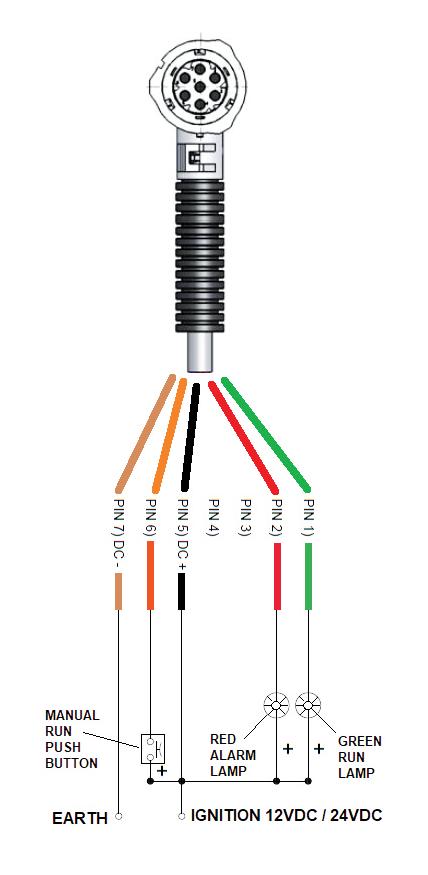
MANUAL RUN PUSH BUTTON
Start from E-CM (Complete Menu Mode)
Select E-AC using Press Select using AC-0 cycle alarm not enabled AC-1 cycle alarm enabled Press to confirm

In the event of an alarm, the display will show bloc. This alarm blocks the pump if triggered

Isolate unless button fitted
MAIN POWER SOCKET
5m power cable assy 40CBL510AK
10m power cable assy
40.CBL.5.10.AK
M12x1 CABLE SOCKET
Connect to –
High Pressure Switch 097127 And enable E-AP in controller

Isolate unless lights fitted
ALTERNATIVELY – FOR FULL VOLUME CONTROL MONITORING
Connect to –
Master divider proximity switch
And enable FU.PC mode And enable E-AC in controller
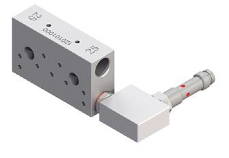
ALEMLUBE ILC-MAX PUMP ELEMENTS

Two types of pump elements are available
90.900.0 FIXED VOLUME
0.160cc/revolution
Includes banjo relief valve assy A70095133 OUTLET – ¼”BSP
90.900.3 ADJUSTABLE VOLUME
Volume adjustable from
0.01cc/revolution to 0.16cc/revolution
Includes relief valve A68075011 OUTLET – ¼”BSP


ALEMLUBE ILC-MAX PUMP ELEMENT INSTALLATION
Only install pump elements when the pump power cable is unplugged.
• First Remove the covering plug from the pump element port
• Clear grease from inside the pump – use a finger to push the grease away and feel where the eccentric and the catch ring are located inside
• Extend the pump element piston to 30mm
• Insert the piston and pump element into the housing on an upward angle so that the piston head touches the eccentric
• Move the pump element into a horizontal position
• The piston head must run in the groove between the eccentric and the catch ring
• Engage the thread and tighten the pump element just a few turns
• Plug the power cable back in and start the pump
• Slowly tighten the pump element until tight, ensuring that the pump is rotating smoothly and grease is beginning to be discharged
• Torque the pump element to 25-30 Newton Metres maximum
• For removal, reverse the above procedure ensuring that the piston is not left behind inside the pump housing
Adjustment Procedure
The delivery rate of the pumping element can be adjusted by loosening the locking nut (c) and rotating the adjustment screw (b) clockwise to reduce delivery, or counter clockwise to increase delivery. The output adjustment table shows the outputs that can be obtained by varying the distance (A) of the adjustment screw.

IMPORTANT: DO NOT ADJUST DISTANCE “A” LONGER THAN 23.6mm

