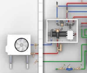
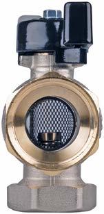
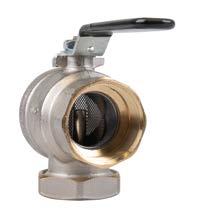
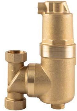
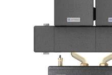
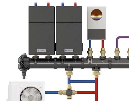
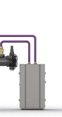
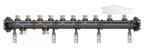
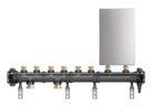
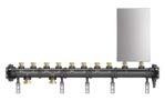
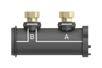
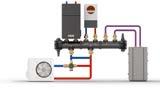
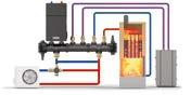
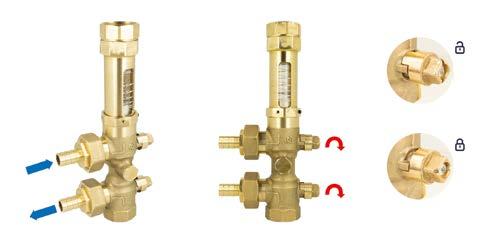
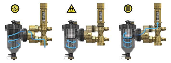
As skilled labour is becoming scarcer and demands on technical solutions are increasing, we have made it our mission to provide you with the best possible support in the form of future-oriented products. As your reliable HVAC partner, we are fully aware of the fact that efficiency, flexibility and quality are more important today than ever before.
Our New Products 2026 catalogue covers innovative DOMESTIC TECHNOLOGY products for safety and measuring equipment for heating systems, solutions for energy savings and alarm units that can be integrated into smart home systems.
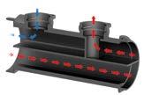
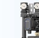
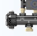
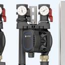
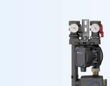
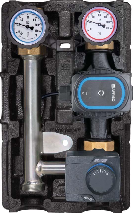
Discover product innovations that are taking centre stage in the industry: Completely pre-assembled system assemblies. Such assemblies help to save you time in planning and installation. These products are made of durable polymer materials, for example. These high-grade plastics are particularly robust and resistant and have a low carbon footprint thanks to our "Green Production" philosophy.
Our objective is to make your day-to-day work easier and to enable you to deliver the best quality even when demand is high in the future.
We look forward to a successful cooperation.
Best regards,
Matthias Blasinger Managing Director Sales and Distribution
AFRISO-EURO-INDEX GmbH
The product package contains the specified number of products or can be delivered in the specified order quantity.
An additional package contains the specified number of products.
Ordering code example = in-stock items All stock items have part numbers printed in blue Questions on the product:
Transformation of the heat market.
Technology-neutral for a sustainable, safe heat transition
For decades, AFRISO has been working on the idea that there must be alternatives to fuel oil and radiators in heating systems. The production start of manifold systems for underfloor heating systems in the 1980s was the initial milestone. This was followed by a wide range of projects for various types of heat generators. Backed by this comprehensive experience, we are now able to provide the right components for the heat sources of the future.
We believe that a sustainable energy transition can only succeed if different technologies and resources can be utilised simultaneously. Renewable energies will, of course, be key in this.
Biogas
Hydrogen
We have identified four key areas in the energy transition on the heating system market, for which we would like to be your reliable partner:
1. Green Fuels Ready: Liquid fuels as a transition technology
Synthetically produced paraffinic fuels can contribute to paving the way to zero CO2 emissions. Therefore, we are optimising our "oil products" on an ongoing basis. AFRISO components are suitable for FAME admixtures and also bear the "Green Fuels Ready"’ label of the BDH (Federal Association of the German Heating Industry). The future has already begun for your fuel oil heating customers: Classic fuel oil, e-fuels and biofuels can be mixed, and the proportion of climate-neutral energy can be continuously increased to 100% CO2 neutrality over the next few years.
2. Green production
Our mission statement "Technology for Environmental Protection" also relates to our corporate responsibility, and we are committed to constantly optimising our own production from an ecological point of view. Next to optimum technology, sustainability always takes centre stage. When we develop new products, we invest maximum effort in weight optimisation, multiple use of parts, recyclability, maximum possible in-house contribution to the product and reduction of transport routes to the place of use.
3. Rapid results through efficient use
Modernising heating systems on an ongoing basis to maximise energy savings immediately results in improved environmental protection and more efficient use of resources. In this area, we provide hydraulic connection systems, energy-efficient pump assemblies, manifold systems and clever valve and control technology. Our pre-assembled components can be used independently of the heating system so that this asset can continue to be used even if the heat source is changed.
4. Conversion of decommissioned fuel oil consuming systems
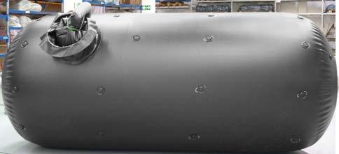
If the end customer opts for a change of technology when a new system is installed, we can provide solutions that allow to reuse existing components in a sustainable way. For example, an AFRISO inner lining for rainwater quickly converts an old steel tank into the basis for a modern rainwater harvesting system.
Together, we make the world more sustainable
For many, sustainability is trendy. Many companies have now jumped on the sustainability bandwagon. We were instrumental in putting this train on the track more than 50 years ago. Today, ecological thinking is firmly anchored in our products and corporate processes. For us, sustainable business means securing business success in the long term while protecting natural resources.
Green production
The "Green Production" label underpins that sustainability takes centre stage. Using plastic as an essential raw material allows us to manufacture our products with low material input and energy consumption. We control most of the processes ourselves and are not dependent on suppliers. This dramatically reduces transport routes. For example, in the Güglingen plant, everything from tool design to plastic injection moulding to final assembly is performed on a 250 m production line. Therefore, our products have always had an extremely small CO2 footprint. Replacing metal with plastic accelerates this.
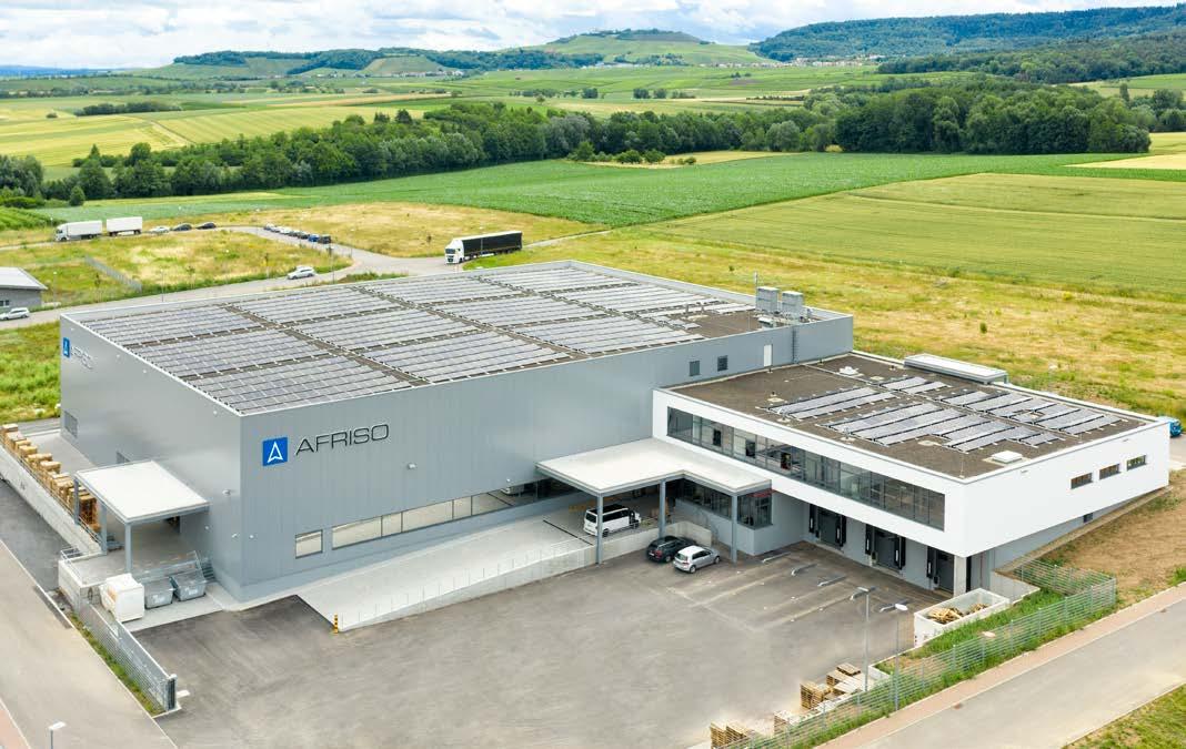
In the new logistics and service centre, building technology operational processes are perfectly aligned: Electricity from the 2,078 m² photovoltaic area is used to operate the forklift trucks, heat pumps and electric vehicles for shuttling between the plant halls.
Short transport routes are beneficial for the environment.
Sustainable. Durable. Made in Germany.
Technology for environmental protection is not just a slogan for AFRISO, but has also been our performance promise for decades: It underpins our claim to manufacture technologically advanced products in Germany in a particularly sustainable way.
This is based on the highest possible vertical integration: From development to in-house tool and equipment design and construction to plastic injection moulding with state-of-the-art, energy-efficient machines, all competencies are combined in-house and can therefore be directly influenced at any time. All production processes are optimised in an ongoing basis from an ecological perspective.
1981
Setting new standards with premium products made of polymers
High-quality polymers have turned out to be ideal for realising this strategic production orientation and as a basic material for sustainable products.
Polymer makes all the difference
The use of plastic significantly reduces the weight of the products. This way, it is possible to create extremely compact designs or assemblies without accepting tradeoffs with regard to stability and robustness. This facilitates makes handling and installation and also contributes to efficiency and reliability in operation. The robust assemblies are resistant to mechanical loads, temperature fluctuations and other environmental influences.
Reliably in use, even after 40 years
AFRISO polymer products
MADEIN GERMANY MADEIN GERMANY
Market launch of the first compact plastic manifold made for surface heating systems
AFRISO support centres – close by, guaranteed.
Sites in Germany
We ensure that you get professional, personal service
With a staff of more than 80 field and internal sales experts! Please visit www.afriso.com/contact for further information on your specific contact person.
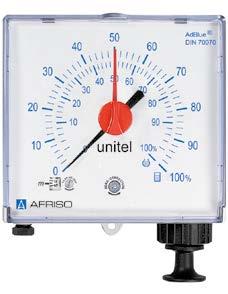
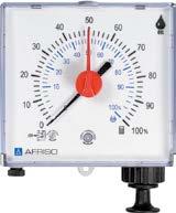
Pneumatic level indicator for AdBlue® – Unitel-Set AdBlue
Specially calibrated for AdBlue®
Universally adjustable
Easy mounting
Complete with special mounting kit
No power supply required
Application
Description
Technical specifications
For level measurement in tanks containing AdBlue® (density 1.09 g/cm3). For tank heights from 700 to 2,300 mm. Suitable for use in flood hazard areas and for remote indication up to 50 m. The term AdBlue ® is the same as "NOx Reducing Agent AUS 32" and "Urea solution 32.5 %".
Universal, pneumatic level indicator with capsule movement. Specially adjusted to the specific weight (density) of AdBlue® = 1.09 g/cm3. Fully adjustable from 700 to 2,300 mm tank height. Measuring accuracy ±3 % of full scale value. Indication in percentage of level. With zero correction at the front side. Universal measuring line connection for pipe or hose with an outside diameter of 6 mm. Easy mounting by means of a mounting kit specially designed for AdBlue®. Process connection G1 and G½, standpipe PVC 2.5 m with stainless steel balance chamber, 17 m measuring line PVC 4 x 1 mm, reducer G1 x G1½ x G2. Watertight up to 10 m water column.
Measuring range
0/700 to 0/2,300 mm tank height
Measuring accuracy
±3 % of full scale value
Operating temperature range
Medium: 0/35 °C
Ambient: –5/+55 °C
(Please observe the pertinent regulations concerning the storage of AdBlue®!)
Scale (displayed values)
Dual scale 0/100 % liquid level
Outer for rectangular tanks, inner for cylindrical tanks
Housing
Wall mounting housing made of impact-resistant plastic with integrated hand-operated pump
W x H x D: 145 x 135 x 65 mm
Process connection
G½ and G1, reducer G1 x G1½ x G2
Standpipe
Plastic PVC
Length 2.5 m balance chamber stainless steel
Measuring line
PVC hose 4 x 1 mm
Length approx. 17 m
Scope of delivery
Level indicator and mounting kit consisting of screw fittings G½ and G1, reducers
G1 x G1½ x G2, 20 m hose with bottom part
i
Make sure to observe all pertinent legislation concerning selection of materials and construction when building storage facilities for AdBlue®
See chapter 2 for suitable overfill prevention systems and chapter 3 for inner tank linings.
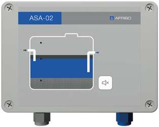
Alarm unit for separators ASA-02
■ For oil, petrol and grease separators
■ With layer thickness alarm
■ Optional overflow alarm and/or sand/sludge alarm
■ With Ex approval for use in zone 0
Application
Oil, grease and petrol pose a great hazard to groundwater and waste water. ASA-02 monitors the layer thickness of separated liquid in oil, petrol and grease separators and generates an alarm signal when it is time to drain the separator.
With the optional retrofittable overflow probe and the sand/sludge probe, it is possible to detect the maximum permissible level and/or a layer of solids in the separator. This avoids overflows that may be caused by clogged outlets or other circumstances. The unit keeps harmful substances from reaching the sewage water system.
Description
Technical specifications
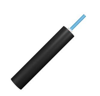
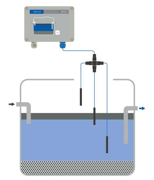
The base system ASA-02 consists of a control unit and a capacitance probe ASA-LP to monitor the layer thickness of oil, petrol or grease layers. The control unit is equipped with 3 configurable relay outputs, visual and audible alarms as well as an acknowledge button. The ASA-LP layer thickness probe is mounted below the constant level of the separator. As soon as the oil, petrol or grease layer reaches the critical level, the device generates an alarm signal.
Optionally, the maximum level can also be monitored with the ASA-OP overflow probe and the sand and sludge deposits with the ASA-SP sand/sludge probe.
Capacitance probe for detecting when a preset threshold value of the oil/grease layer is exceeded
Sludge probe ASA-SP
Ultrasonic probe for detecting when a preset threshold value of the sand/sludge layer is exceeded
Connection example
Capacitance probe for detecting a high level in the separator
① = Alarm unit for separators ASA-02
② = Bus connector ASA
③ = Overflow probe ASA-OP
④ = Layer thickness probe ASA-LP
⑤ = Sand/sludge probe ASA-SP
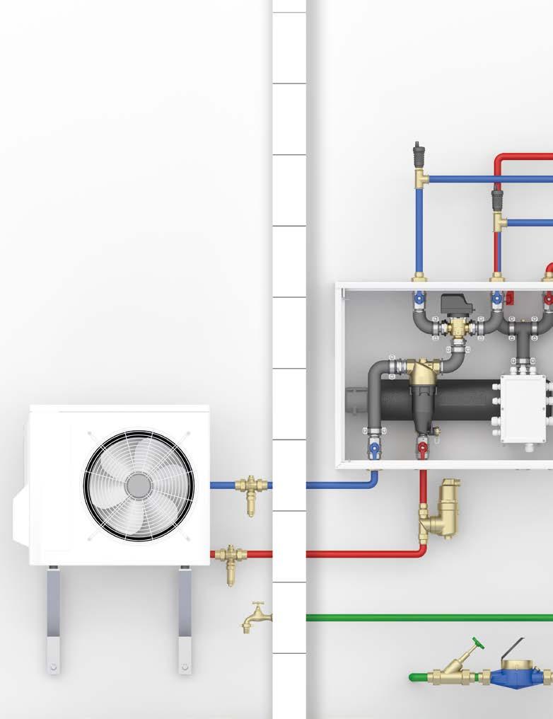
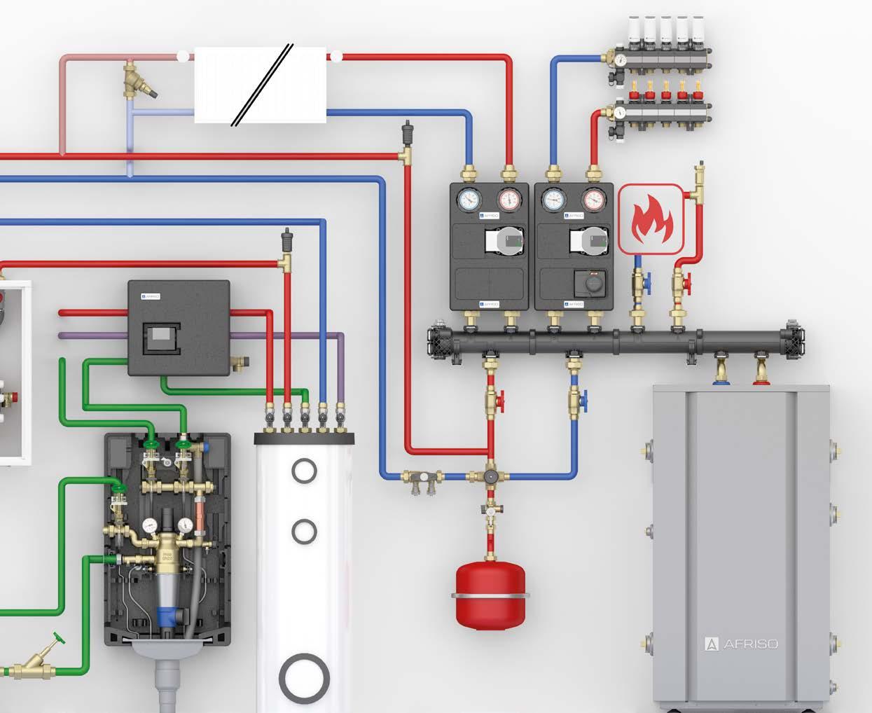
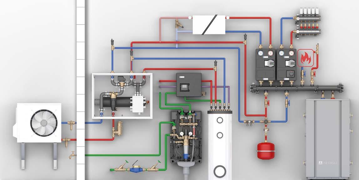
1 Frost protection valves AAV
2 Air separator G1
3 Hydraulics module AMB 900 as a pre-installed assembly in a metal enclosure
4 Quick air vent PrimoVent Hybrid
5 Domestic water station HWSC
6 Hot water circulation unit WZS 100
7 Differential pressure bypass valve DPOH
8 Filling and fl ushing fi tting
9 Anti-tamper cap valve with integrated boiler filling and drain valve KFE
10 Return temperature limiter
11 Heating pump assemblies PrimoTherm ® K 180-2 with ProClick actuator and mixer with adjustable flow coefficient Kvs
12 Motorised actuators MSA 10 DT for automatic hydraulic balancing
13 Polymer manifold ProCalida ® MC 1 for heating and cooling
14 Quick air vent PrimoVent brass
15 Polymer heat source manifold HSM for intelligent distribution of heating circuit water and supply
16 Heating water buffer tank ABT 160
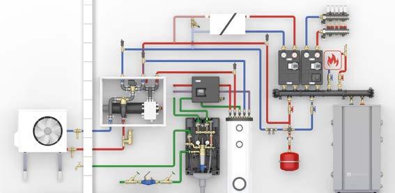
The increasing level of diversity and customisation of heating systems leads to more complexity. This development results in new challenges for the industry with regard to efficient systems and heat distribution. AFRISO
provides support with pre-assembled system assemblies and platform solutions for the interaction of a wide variety of heating concepts.
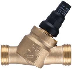
Differential pressure bypass valve DPOH
■ Ensure the minimum flow of a heat generator/chiller
■ Avoids flow noise
■ With directly readable adjustment scale
■ Differential pressure fully adjustable
■ Available as space-saving angled version or straight version and as kit for mounting to manifold
Mounting example in heating circuit, upstream of consumer
Application
Description
Technical specifications
To maintain the minimum flow rate in the heat generator, regardless of the number of open heating circuits in the heat distribution system.
Differential pressure bypass valve with directly readable adjustment scale. Housing made of brass. Available as straight version or angled version for space-saving installation.
The bypass valve is adjusted (with closed heating circuits) in such a way that the minimum volume flow of the heat generator is maintained. The minimum volume flow is essential for heat pumps, for example, during defrosting mode and cooling mode.
Operating temperature range
Max. 95 °C, (short-term 120 °C)
Operating pressure
Max. 6 bar
Differential pressure
Fully adjustable 0.1 to 0.5 bar
Housing
Angled version or straight version
Material: Brass
Differential pressure bypass valve
DPOH SET G1 union nut x G1 male, kit for mounting to manifold
Connection (straight/angled version) Inlet: G1 male or G1 female, flat-sealing Outlet: G1 male, flat-sealing
Connection of kit for mounting to manifold Inlet: G1 female and male, flat-sealing Outlet: G1 female and male, flat-sealing
Hydraulics module AMB 900
■ Pre-installed, tightness-tested indoor unit, ready to be connected
■ Integrated heating element: 3, 6 and 9 kW
■ With magnetite sludge separator and reversing valve
■ Maximum time savings: No planning of hydraulics, no error sources during mounting
Application
AMB 900 is a specially developed indoor unit for use in closed heating systems as per EN 12828. It allows for simple, reliable and fast integration of monobloc heat pumps into existing or new heating systems. The factory-preassembled and tightness tested unit is installed inside the building between the heat pump and the hot water storage tank or the heat distribution system. Thanks to the pre-wired components, it is sufficient to wire the power supply and connect the unit to the heat pump. With to the integrated electric heating element, AMB 900 can also be used as an auxiliary or emergency heater in combination with the heat pump control.
Description
Technical specifications
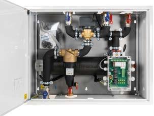
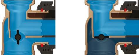
Hydraulics module AMB 900 in a compact metal cabinet with electrically and mechanically pre-assembled components. It contains a 9 kW heating element, a 3-way reversing valve AZV 844 and a magnetite sludge separator ADS 181 specially designed for heat pumps. It features a large filter surface and optimised flow for minimum pressure loss. An extra-strong magnet quickly and reliably separates magnetite. The 3-way reversing valve allows you to switch between the heating circuit and the hot water tank.
Integrated safety-related equipment such as 3 bar safety valve, safety temperature cut out, quick air vent and shut-off valves minimise potential errors during installation and ensure reliable operation. The installation is "plug & play": fit the metal plate to the wall using the prepared eyelets, connect system lines with standard connections and then fit the metal housing without tools.
System connections
Heat pump: G1¼ union nut
Heating circuit: G1¼ union nut
Operating temperature range
Medium: 5–90 °C
System pressure
Max. 3 bar
Flow coeffi cient Kvs
6.5 m³/h
Power heating element Heizstab
Max. 3 kW at 230 V AC
Max. 9 kW at 400 V AC
Heat pump power
Max. 16 kW
Dimensions
W x H x D: 765 x 577 x 252 mm
Magnet insert
Neodymium 14,000 Gs
Hydraulics module AMB 900
Frost protection valves AAV
Heating pump assembly PrimoTherm® K 180-1 3 Buffer tank ABT 50
Underfloor heating circuit manifold
Ball valve KH with fi lter and magnet
■ Shut-off element for universal use with heating systems
■ Integrated filter sieve and magnet as dirt collector
■ Easy cleaning
■ Nickel-plated housing
Application
Description Technical specifications
Ideal for all applications in heating systems that require an additional filter function against lime, rust, sludge or other contaminants is required. The installation of shut-off elements in heating systems is essential for subsequent maintenance.
Nickel-plated ball valve as shut-off element with integrated filter sieve and strong magnets. You can clean the unit without unpressurising and draining the system. For cleaning, the ball valve is simply closed and the filter sieve and magnet are cleaned by removing the cap on the underside.
Housing Brass, nickel-plated
Filters
Stainless steel
Operating pressure 16 bar (PN 16)
Operating temperature range
–20/+90 °C (short-term 120°C)
Mesh size fi lter
0.65 mm
Magnet
Neodymium 1.2 T (12,000 Gs)
Mounting position
Preferably vertical
Flow coeffi cients Kvs
G¾: 2.8 m3/h
G1: 5.9 m3/h
G1¾: 13 m3/h
Options
■ Other nominal sizes
■ Other handle (colour/shape)
■ Other connection threads
Ball valve G1¼ female thread with filter/magnet
Ball valve KH with fi lter and magnet
Dimensions (mm)
Ball valve G¾ female thread with filter/magnet
Ball valve G1 female thread with filter/magnet
Ball valve G1¼ female thread with filter/magnet
Air separator G1
■ Optimum separation of micro air bubbles
■ Extends the service life of the system and ensures optimum system efficiency
■ Maintenance-free operation
■ Ideal for large water volumes thanks to low pressure loss
Application
Description
Technical specifications
For removing air from heating systems. The air separator ensures reliable operation as well as better and faster heat transfer. Suitable for all types of hot water heating systems and underfloor heating systems.
Compact air separator with integrated vent valve. When the system water flows through the air separator, air bubbles are effectively separated from the medium and collect in the venting area. When a certain amount of air is collected, the vent valve opens automatically and the air escapes.
The air separator G1 is suitable for mounting in vertical and horizontal pipes. The connection piece (T piece) and the vent valve can be rotated by 360° around their axes.
Housing Brass
Operating pressure
Max. 10 bar
Flow coeffi cient Kvs 20.44 m³/h
Operating temperature range
Medium: –10/+110 °C
Ambient: 0/90 °C
Connection thread
2 x G1 female
Mounting position Horizontal and or vertical
Dimensions (mm)
Manual air vent PrimoVent SV
Application
Reliable venting of heat pump systems with flammable refrigerants
Secure the hydraulic circuit against uncontrolled leakage of refrigerant
Screw it in and you're done: Vent with O ring seal
Also available with mounting valve
Mounting valve for easy, fast mounting or dismounting without draining the system.
Description
For manual venting of sealed heating systems as per EN 12828. Suitable for up to 12 bar/110 °C for water and water/glycol mixtures with up to 50 % glycol. Ideal for heat pump systems with flammable refrigerant to help ensure that no refrigerant escapes from the hydraulic circuit in an uncontrolled manner.
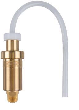
Manual air vent with collection chamber. During system operation, the integrated air collection chamber allows to capture air or gas bubbles, keeping them from getting into the piping. The manual air vent is opened by hand during the venting phase. The enclosed drain hose allows you collect the escaping water in a collection container (provided by the customer) in a controlled manner.
Its high, narrow design is perfect in terms of appearance and function.
Technical
specifications Connection
G3/8 or G½
Operating temperature range
Max. 110 °C
Nominal pressure
Max. 12 bar
Housing
Brass
Hand wheel
POM
Drain hose
Silicone
Length: 40 cm
Scope of delivery
■ Manual air vent
■ Drain hose
■ Part no. 77326 with mounting valve
Mounting valves as accessories for quick air vents:
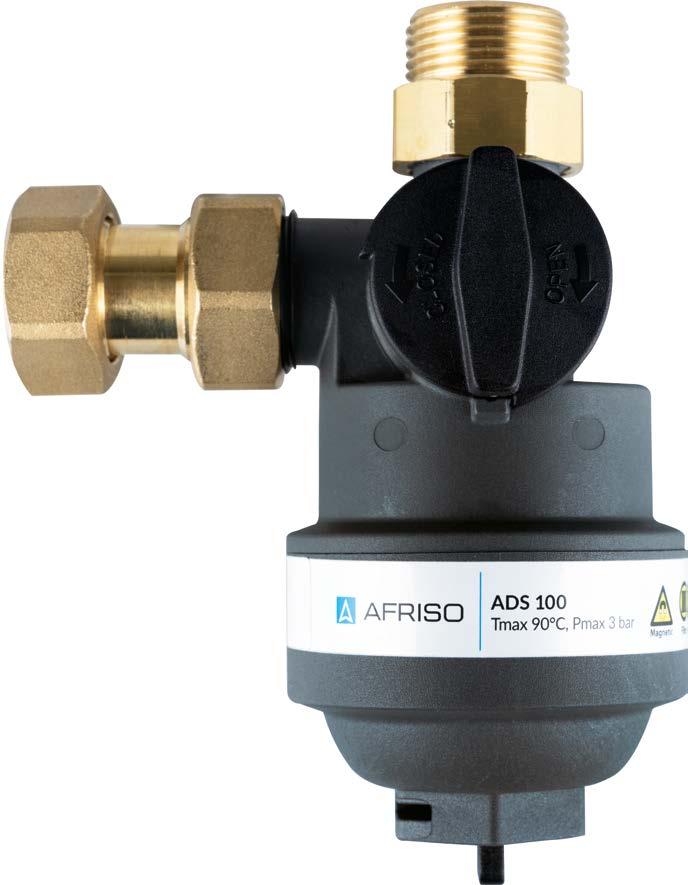
Magnetite sludge separator ADS 100
Flexible connection
Two connection possibilities for horizontal and vertical mounting to pipes.
kundenspezi
individuell
Sonderanfertigungen & Systemlösungen
Inztegrated shut-off valve
Magnetite capture
A powerful magnet (12,000 Gs) removes metal particles such as rust or metal chips from the inflowing water.
Robust design
Housing made of high-grade polymers (PA66) with 30 % glass fiber for corrosion-free, long-term operation in heating and cooling applications.
800-μm mesh filter
A dense stainless steel mesh removes all impurities and particles with a size of more than 0.8 mm.
Advantages – your benefi ts
Ideal for installation below wall-mounted condensing gas boilers with up to 35 kW
Highly compact design with integrated shut-off valve for applications where space is limited
In spite of its compact design and dual-stage filtration, the separator has a flow coefficient Kvs of 4.2 m³/h at a relatively high volume flow
Magnetite sludge separator
ADS 100
Application
Description
Technical specifications
Effective separation of particles by means of magnet insert and filter sieve
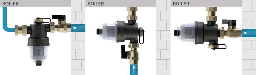
For applications where space is limited: Horizontal or vertical mounting possible
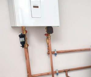
Designed for continuous removal of solid impurities from heating systems that can damage other system components (such as heat exchangers, condensers, valves, pumps). The sludge separator ensures clean water, reliable operation, better and faster heat transfer and thus contributes to reduced fuel consumption and emissions. Suitable for hot water heating systems, underfloor heating systems and other system equipment with water/glycol mixtures. Rust, lime particles, calcium, magnesium, oxides, carbonates and sludge as well as larger particles such as metal chips or construction residues are removed from the water – without the use of chemicals. Ideally, the unit is installed in the return line upstream of the heat generator.
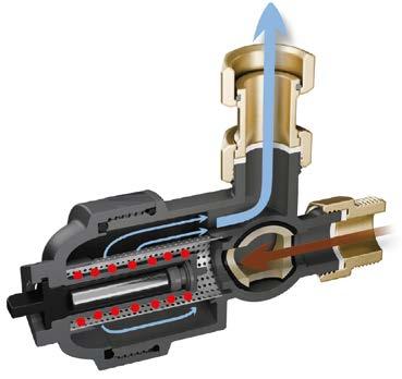
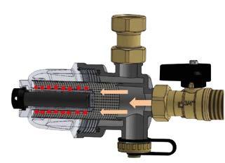
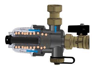
Extremely compact sludge separator with drain valve and magnet insert. When the system water flows into the separator, metallic particles such as rust or metal chips are removed by a strong magnet. Other, non-metallic particles are removed by a 800 µm stainless steel sieve. Collected impurities can be removed quickly via the integrated drain valve. The mounting tool included in the scope of delivery allows you to easily disassemble the sludge separator for thorough cleaning.
Housing
Plastic (PA66 with 30 % glass fibre), brass connection parts
Operating pressure
At max. 50 °C: 6 bar
At max. 90 °C: 3 bar
Flow coeffi cient Kvs
4.2 m³/h
Recommended fl ow rate
Max. 1.8 m³/h
Operating temperature range
Ambient: 0/90 °C
Capacity
79 ml
Connection System: G¾
Filter
Material: Stainless steel
Mesh size: 800 µm (pre-assembled)
Magnet insert
Neodymium 1.2 T (12,000 Gs)
Mounting position
Horizontal, vertical
Scope of delivery
■ Magnetite sludge separator with 800 µm filter sieve
■ Mounting tools
Magnetite sludge separator ADS 100
Dimensions (mm)
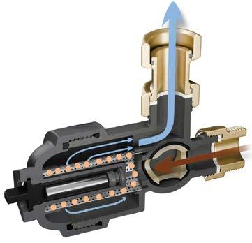
Filter function stage 1
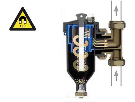
Magnet attracts metallic particles
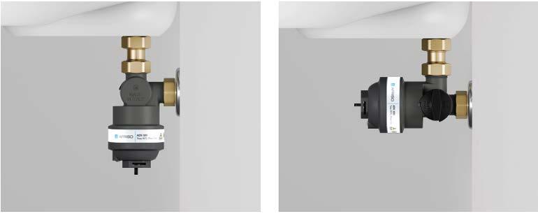
Mounting
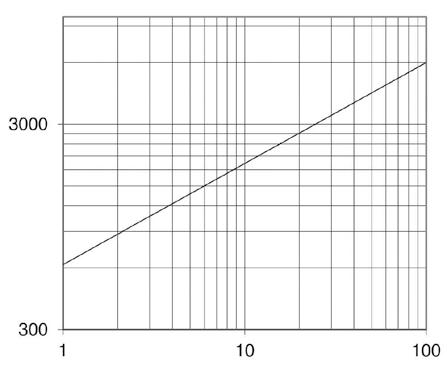
Pressure loss
Diagram pressure loss depending on flow rate.
Filter function stage 2
Impurities are removed by the stainless steel sieve
Can be mounted below wall-mounted heat generators (for example, condensing gas boilers)
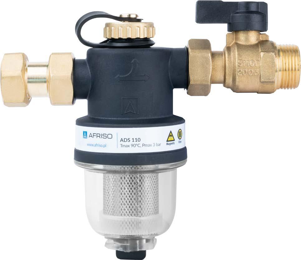
Magnetite sludge separator ADS 110
Flexible connection
Three connection possibilities for horizontal and vertical mounting to pipes. Angular 90° connection is also provided for.
Robust design
Housing made of high-grade polymers (PA66) with 30 % glass fiber for corrosion-free, long-term operation in heating and cooling applications.
Fast visual inspection
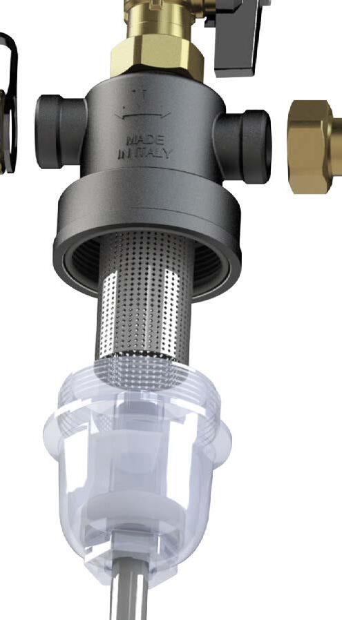
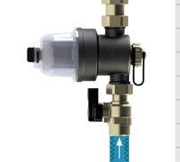
Thanks to the transparent filter cup the degree of contamination can be seen at a glance.
800-μm mesh filter
A dense stainless steel mesh removes all impurities and particles with a size of more than 0.8 mm.
Advantages – your benefi ts
Magnetite capture
A powerful magnet (12,000 Gs) removes metal particles such as rust or metal chips from the inflowing water.
Ideal for installation below wall-mounted condensing gas boilers with up to 35 kW
Highly compact design for applications where space is limited
In spite of its compact design and dual-stage filtration, the separator has a flow coefficient Kvs of 5.3 m³/h at a relatively high volume flow
Magnetite sludge separator ADS 110
Application
Description
Technical specifications
Effective separation of particles by means of magnet insert and filter sieve
Idela for wall-mounted condensing gas boilers with up to 35 kW
Transparent filter cup for fast visual inspection
For applications where space is limited: Horizontal, vertical or 90° angle installation
Requires little space – ideal for 90°-installation below equipment.
Designed for use below wall-mounted heat generators for continuous removal of solid impurities from heating systems that can damage other system components (heat exchangers, condensers, valves, pumps, etc.).
The sludge separator ensures clean water, reliable operation, better and faster heat transfer and thus contributes to reduced fuel consumption and emissions. Suitable for hot water heating systems, underfloor heating systems and other system equipment with water/glycol mixtures. Rust, lime particles, calcium, magnesium, oxides, carbonates and sludge as well as larger particles such as metal chips or construction residues are removed from the water – without the use of chemicals. Ideally, the unit is installed in the return line upstream of the heat generator.
Extremely compact sludge separator with drain valve, transparent filter cup and magnet insert. When the system water flows into the separator, metallic particles such as rust or metal chips are removed by a strong magnet. Other, non-metallic particles are removed by a 800 µm stainless steel sieve. Collected impurities can be removed quickly via the integrated drain valve.
The mounting tool included in the scope of delivery allows you to easily disassemble the sludge separator for thorough cleaning.
Housing
Plastic (PA66 with 30 % glass fibre), brass connection parts
Operating pressure
At max. 50 °C: 6 bar
At max. 90 °C: 3 bar
Flow coeffi cient Kvs
5.3 m³/h
Recommended fl ow rate
Max. 2.0 m³/h
Operating temperature range
Ambient: 0/90 °C
Capacity 139 ml
Connection
System: G¾
Filter
Material: Stainless steel
Mesh size: 800 µm (pre-assembled)
Magnet insert
Neodymium 1.2 T (12,000 Gs)
Mounting position
Horizontal, vertical, 90° angle
Scope of delivery
■ Magnetite sludge separator with 800 µm filter sieve
■ Mounting tools
Magnetite sludge separator ADS 110
Dimensions (mm)
Pressure loss
Diagram pressure loss depending on flow rate.
Step 1
Magnet attracts metallic particles
Mounting
Filter function stage 2
Impurities are removed by the stainless steel sieve
Can be mounted below wall-mounted heat generators (for example, condensing gas boilers)
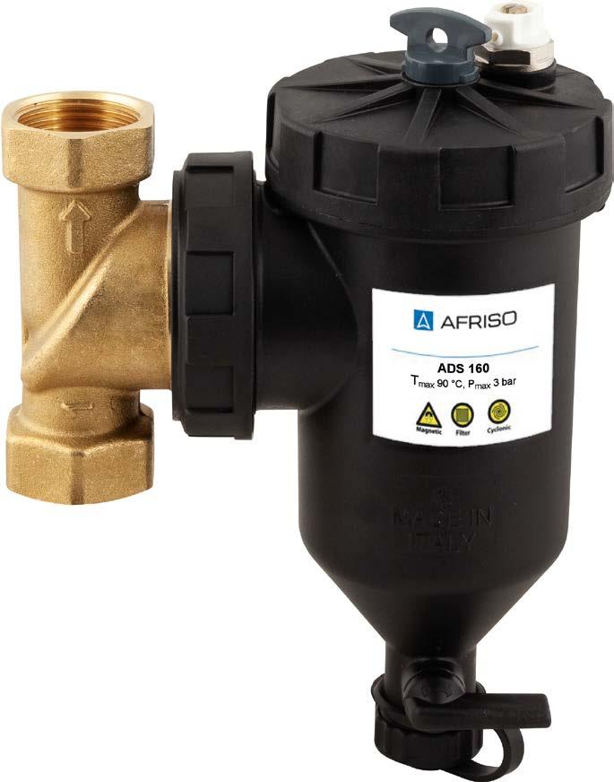
Magnetite sludge separator ADS 160
Mounting
The rotatable connection allows mounting to horizontal, vertical and diagonal pipes. System connections G¾, G1 and G1¼ possible.
Vent
With the manual air vent, venting is possible in a controlled manner during maintenance.
Convenient operation
Mounting tool for modifying the position of the connection flange or removing the cover for thorough cleaning of the sludge separator.
Quickly thermally insulated
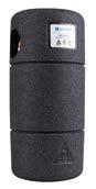
The form-fit EPP heat insulation reduces installation time and limits heat loss.
Easy emptying
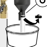
Collected impurities can be removed quickly via the integrated drain valve at the bottom of the separator.
Advantages
Security
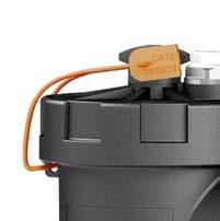
An anti-tamper seal protects the magnet from unauthorised removal. The date of the most recent maintenance work can also be noted here.
High capacity
Dirt collector with high capacity (400 ml).
– your benefi ts
Ideal protection for all heat generators
In spite of its compact design and triplestage filtration, the separator has an excellent flow coefficient Kvs at a relatively high volume flow
3 filtration stages
Via flow effect: Separation with strong magnet and mesh filter 500 µm or 800 µm.
Magnetite sludge separator
ADS 160
Application
■ Effective separation of particles by means of three filtration stages
■ Extends the service life of the system and ensures optimum system efficiency
■ Easy operation and cleaning
■ Flexible mounting, vertical, horizontal or diagonal
■ Optional EPP heat insulation
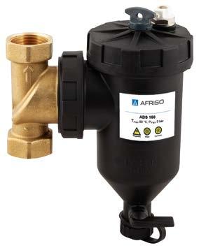
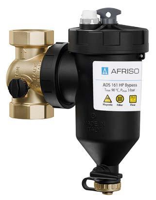
For continuous removal of solid impurities from heating systems that can damage other system components (such as heat exchangers, condensers, valves, pumps). The sludge separator ensures clean water, reliable operation, better and faster heat transfer and thus contributes to reduced fuel consumption and emissions. Suitable for hot water heating systems, underfloor heating systems and other system equipment with water/glycol mixtures. Rust, lime particles, calcium, magnesium, oxides, carbonates and sludge as well as larger particles such as metal chips or construction residues are removed from the water – without the use of chemicals. Ideally, the unit is installed in the return line upstream of the heat generator.
Description
Technical specifications
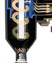
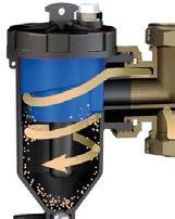
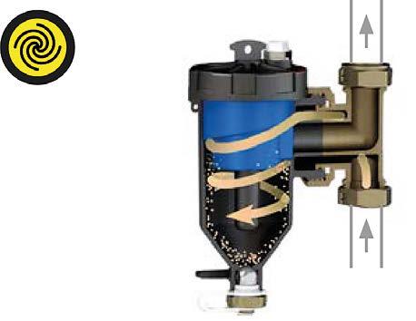
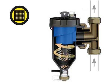
Compact sludge separator with drain valve and magnet insert and optional form-fit heat insulation. When the system water flows into the separator, it starts to swirl. This causes a cyclonic movement of the medium, causing impurities to separate and settle in the lower part of ADS 160. There, metallic particles are attracted by a strong magnet. Other, non-metallic particles are removed by a 500 µm stainless steel sieve. The collected impurities can be easily removed via the drain valve. A manual air vent is integrated in the cover. The mounting tool allows you to easily disassemble the sludge separator for thorough cleaning. Accessories include an additional stainless steel sieve with a greater mesh size, an anti-tamper seal to secure the magnet and spare O rings.
Housing
Plastic (PA66 with 30 % glass fibre), brass connection parts
Operating pressure
At max. 50 °C: 6 bar
At max. 90 °C: 3 bar
Flow coeffi cients Kvs
ADS 160: 6.9 m³/h
ADS 161: 7.4 m³/h
ADS 164: 6.6 m³/h
Recommended fl ow rate
Max. 2.7 m³/h
Operating temperature range
Ambient: 0/90 °C
Capacity
400 ml
Connections
System: G¾ female, G1 IG or G1¼ female
Vent: G½ female
Filter
Material: Stainless steel
Mesh size:
500 µm (pre-assembled)
800 µm (accessories)
Magnet insert
Neodymium 1.4 T (14,000 Gs)
Mounting position
Vertical, horizontal or diagonal
Scope of delivery
■ Magnetite sludge separator with 500 µm filter sieve
■ Filter sieve 800 µm
■ Mounting tools
■ Anti-tamper seal
■ 2 spare seals
Magnetite sludge separator ADS 160
Dimensions (mm) and principle of operation
Pressure loss
Diagram pressure loss depending on flow rate
Flow rate (l/h)
ADS 164 ¾" up to Ø 22
ADS 160 ¾" up to Ø 22
ADS 164 1" up to Ø 28
ADS 160 1" up to Ø 28
ADS 164 1" up to ¼
ADS 0161 bypass closed ADS 0161 bypass closed
loss (kPa)
Filter function stage 2
Magnet attracts metallic particles
Filter function stage 1
Inflow in a spiral movement
Filter function stage 3
Impurities are removed by the stainless steel sieve
Magnetite sludge separator ADS 160
Further details on how it works: Sludge separator series ADS 160
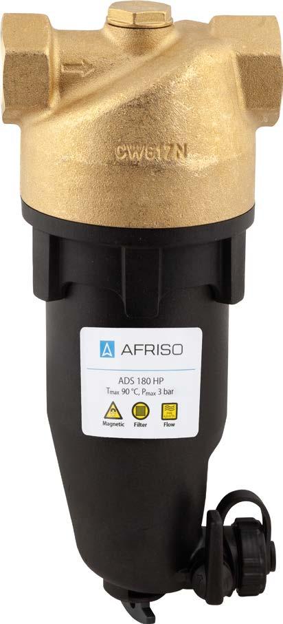
Magnetite sludge separator ADS 180
High flow rate
Ideal for heat pump application due to the high flow rate of 17.1 m3/h.
Direction of flow
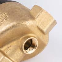
The arrow on the housing indicates the direction of flow of the medium.
Quickly thermally insulated
The form-fit EPP heat insulation reduces installation time and limits heat loss.
Magnetite capture
The powerful magnet (14,000 Gs) removes metal particles such as rust or metal chips from the inflowing water.
Advantages – your benefi ts
Connection for vent valves
Optional manual air vent for venting in a controlled manner during maintenance. It is also possible to mount the quick air vent Primovent brass with aqua stop.
800-μm mesh filter
The large filter surface and the optimised flow ensure a pressure loss as low as possible.
Easy emptying
Collected impurities can be removed quickly via the integrated drain valve at the bottom of the separator.
Ideal protection for heat generators with a high flow rate
In spite of its compact design and dual-stage filtration, the separator has an excellent flow coefficient Kvs at a relatively high volume flow
Impressive magnetite separation rate: The special arrangement of the individual magnets provides for an active contact surface that is up to 30 % larger than that of other commercially available magnetite sludge separators
Magnetite sludge separator
ADS 180
■ Effective separation of particles by means of magnet insert and filter sieve
■ Extends the service life of the system and ensures optimum system efficiency
■ Easy operation and cleaning
■ Ideal for large water volumes thanks to low pressure loss
Application
Description
Technical specifications
For continuous removal of solid impurities from heating systems that can damage other system components (such as heat exchangers, condensers, valves, pumps). The sludge separator ensures clean water, reliable operation, better and faster heat transfer and thus contributes to reduced fuel consumption and emissions. Suitable for hot water heating systems, underfloor heating systems and other system equipment with water/glycol mixtures. Rust, lime particles, calcium, magnesium, oxides, carbonates and sludge as well as larger particles such as metal chips or construction residues are removed from the water – without the use of chemicals. Ideally, the unit is installed in the return line upstream of the heat generator.
Compact sludge separator with drain valve and magnet insert. When the system water flows into the separator, metallic particles such as rust or metal chips are removed by a strong magnet. Other, non-metallic particles are removed by a 800 µm stainless steel sieve. Collected impurities can be removed quickly via the integrated drain valve.
The upper part of the housing contains a connection thread G½ which is closed by a cap. This is provided for connection of a manual air vent or an automatic quick air vent. The mounting tool included in the scope of delivery allows you to easily disassemble the sludge separator for thorough cleaning.
Housing
Plastic (PA66 with 30 % glass fibre), brass connection parts
Operating pressure
At max. 50 °C: 6 bar
At max. 90 °C: 3 bar
Flow coeffi cients Kvs
ADS 180 G1: 17.1 m³/h
ADS 181 G1¼: 17.18 m³/h
Recommended fl ow rate
Max. 12.5 m³/h
Operating temperature range
Ambient: 0/90 °C
Capacity
440 ml
Connections
System: G1 female or G1¼ female
Vent: G½ female
Filter
Material: Stainless steel
Mesh size: 800 µm (pre-assembled)
Magnet insert
Neodymium 1.4 T (14,000 Gs)
Mounting position
Horizontal
Scope of delivery
■ Magnetite sludge separator with 800 µm filter sieve
■ Mounting tools
Magnetite sludge separator ADS 180
Dimensions (mm)
Filter function stage 1
Magnet attracts metallic particles
Diagram pressure loss depending on flow rate
Filter function stage 2
Impurities are removed by the stainless steel sieve
Heat source manifold HSM
De-aeration with manual vent or quick air vent with flexible orientation for 360°-installation positions.
High-grade polymer material enables compact, light-weight design. Connection of the brass parts via the AFRISO plug-in connection system enables homogeneous recycling at end-of-life.
Buffer segment B Hydraulics adapted matched to operation with buffer storage tanks (e.g. ABT 22/50/160) for minimum volume flow or heat storage in heat pump systems.
Modular segment design HSM 90/125 2 base segments: HSM 90 (G1) with an axis distance of 90 mm and HSM 125 (G1½) with 125 mm.
Allows for optimised warehouse logistics and adaptation to any use case.
Buffer segment for easy combination with buffer tanks
For example, for integration of a small buffer tank to maintain a minimum volume flow in the system. Adjustable bypass with differential pressure bypass valve.
For example, for integration of a system storage buffer to increase efficiency and store thermal energy.
MADEIN GERMANY MADEIN GERMANY
90/125 mm
Heat source manifold HSM
Individual requirements for heating systems and complex system hydraulics call for intelligent heat distribution
Individual requirements for heating systems and complex system hydraulics call for intelligent heat distribution
Modern heating systems are getting more and more complex:
Modern heating systems are getting more and more complex:
■ Heat pumps with or without solar support
■ Heat pumps with or without solar support
■ Hybrid systems in which a heat pump is added to existing heating technology during modernisation
■ Hybrid systems in which a heat pump is added to existing heating technology during modernisation
■ Buffer tanks that ensure a minimum volume and a minimum flow or extend the general heat supply in existing system solutions
■ Buffer tanks that ensure a minimum volume and a minimum flow or extend the general heat supply in existing system solutions
These are just a few examples of the increasing level of diversity and customisation of heating systems. This development results in new challenges for the HVAC industry with regard to efficient heat distribution. With the HSM heat source manifold (patent pending), AFRISO has created the technical basis for implementing a wide variety of concepts based on a standardised platform.
These are just a few examples of the increasing level of diversity and customisation of heating systems. This development results in new challenges for the HVAC industry with regard to efficient heat distribution. With the HSM heat source manifold (patent pending), AFRISO has created the technical basis for implementing a wide variety of concepts based on a standardised platform.
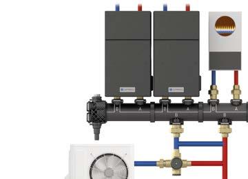
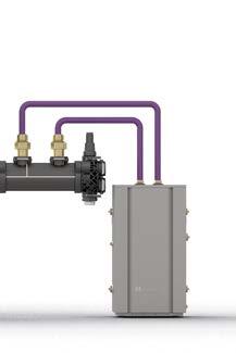
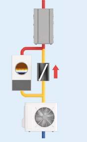
Example of a hybrid heat pump system with fossil fuel heat generator and buffer tank
Example of a hybrid heat pump system with fossil fuel heat generator and buffer tank
Complex system hydraulics easily implemented with few components and minimum effort
Complex system hydraulics easily implemented with few components and minimum effort
Heat source manifold HSM
Heat source manifolds provide for maximum fl exibility during installation
Easy to convert from right to left
The heat source manifold can be rotated to adapt flexibly to local conditions on the construction site. Thanks to the AFRISO plug-in system, the connected pump assemblies can be easily converted from right to left or left to right.
Segment replacement
As opposed to conventional boiler manifolds, the heat source manifold can be flexibly adapted to the conditions on site by replacing segments. Whether you need the flow on the right or left or require more space between the pipes, there are virtually no limits to the flexibility.
Adjustable wall distances
The concept of adjustable wall distances also speeds up and facilitates installation. During installation, the distance to the wall can be adjusted from 80 to 130 mm in practically no time at all, allowing the manifolds and pump assemblies to be optimally adapted to the existing piping on site.
Connection heat pump from the left
Heat source manifold HSM
Prefabricated segment assemblies for adaptation to any application
Hydraulic separator / version with bypass valve
In addition to standard applications, the HSM heat source manifold can also be used to implement systems that require a bypass or a complete hydraulic separator function.
The accessories included in the scope of delivery allow you to replace the separation between the flow and return by a hydraulic separator function. If a bypass valve is needed in the hydraulic system, the differential pressure bypass valve HSM DPO valve can be fitted directly into one of termination components of the manifold. This eliminates the need for additional piping and labour.
The differential pressure bypass valve ensures that a minimum circulation in the heat generator is maintained only when the heating circuits are closed. If the heating circuits are open, there is no bypass. This makes the system particularly efficient, avoiding unnecessary energy losses.
Standard de-aeration at the top De-aeration via the upper chamber, separation between the two chambers
Standard de-aeration at the bottom De-aeration via the bottom chamber, separation between the two chambers
Combination with smart AFRISO buffer tanks
Hydraulic separator function De-aeration via the upper chamber, integrated accessories kit hydraulic separator
System hydraulic with bypass De-aeration via the upper chamber and differential pressure bypass valve
AFRISO buffer tanks can be operated in series. A special connection kit is available allowing the direct connection of the buffer tank to the HSM manifold. System separation is implemented with the buffer tanks. This way, it is possible to install electric backup heaters, for example, to increase the self-consumption of electricity from PV systems.
One termination component – numerous possible functions
HSM with bypass valve
HSM with hydraulic separator function
Heat source manifold HSM
Minimum volume fl ow and heat storage in heat pump systems
Benefi
ts of heat storage in buffer tanks
Buffer tanks are very popular in heat pump applications. There are various reasons for this: On the one hand, buffer volume is used to supply the defrosting energy that a heat pump needs to remove a layer of ice. On the other hand, it is important to obtain a minimum running time for the heat pump to keep it from switching off too quickly.
Extension segment B for buffer tank
For maximum flexibility on the construction site – even storage tanks without special heat exchangers can be integrated as buffer tanks. Depending on your requirements, the buffer can be integrated into the heat pump only or into the entire system. The hydraulics become clearer in spite the complex functionality.
In the case of larger buffer tanks, cost pressure and limited space on site play a role in the decision. Large volumes provide the benefits already mentioned, but can also take over the supply of the heat distribution network in the short to medium term during shutdown periods without energy input from the heat pump. In all cases, storing thermal energy increases the efficiency of the system.
Ensuring minimum system volume and minimum volume fl ow
What can be done if there is no space available for installing buffer storage tanks, but the heat pump manufacturer specifies a minimum system volume and minimum volume flows? Storage tanks are often constructed and utilised with ingenuity and makeshift means. The bypass valve is integrated into the heating circuit, depending on the situation, also in the boiler room – even if this implies that the system volume is no longer used.
System buffer
In order to minimise error potentials and meet the manufacturer's specifications, the bypass valve can be integrated directly into the HSM heat source manifold, and the minimum volume can be ensured via an optional ABT 22 mini buffer tank.
The extension segment B allows you to integrate a buffer tank in such a way that the bypass is also automatically taken into account. The volume flows of the heat pump or pump assemblies to the heating circuits determine whether stratification or discharging takes place. The primary circuit is independent of the secondary circuit due to a hydraulic separator function. This enables smooth operation of the system, especially in renovation projects. If heat is required in the heating circuits, it flows directly from the heat pump circuit via the pump assemblies to the heating circuits without any detours.
account. The volume flows of the heat pump or pump assemdischarging takes place. The primary circuit is independent of the bles smooth operation of the system, especially in renovation from the heat pump circuit via the pump assemblies to the heat-
Heat source manifold HSM
Hybrid applications made easy
Combined operation with different heat generators
Hybrid systems are increasingly becoming the focus of heat generation and are attracting growing interest among end customers: This is due to global factors such as an uncertain supply of fossil fuels, the steadily rising CO2 tax, or even unsettling statements that a heat pump cannot efficiently reach the "high" temperatures in older buildings. System owners see the benefit of continuing to use existing heat generators and, to the extent feasible, supplementing them with a heat pump. In such cases, it is often a challenge to implement the manufacturer's hydraulics specifications in the boiler room. Many components, such as check valves, storage volumes and temperature limiters, require
Effi cient integration of the heat pump into existing oil- or gas-fi red heating systems
installation and coordination. Errors are not uncommon and are often only discovered afterwards when the electricity bill arrives. This is where the modular concept of the heat source manifold comes in, enabling simple and error-free installation without complex planning of the hydraulic system. Time savings reduce costs and existing equipment can be integrated into the system. It is even possible to retrofit a second heat generator at a later point in time. True to the motto: "Who knows what the future holds."
The specially designed HSM hydraulic system allows for the optimum integration of a heat pump into existing oil- or gas-fired heating systems. The focus is on maximum efficiency of the heat pump: The buffer tank extends the running times and reliably prevents frequent on and off cycles
The heat generator is powered solely by the heat pump, preventing unnecessary consumption of fossil fuel. Both heat generators can be operated independently of each other or in parallel without affecting each other. The intelligent connection ensures optimum adjustment of the different volume flows and prevents flow noise in the system.
Genuine plug & play solution for rapid, error-free installation: Hydraulic system completely pre-assembled, everything is clearly labelled and tightness-tested.
Optimal system solution for solid fuel boilers and further heat generators with buffer tanks
The sophisticated hydraulic system design with a system buffer allows for the efficient integration of solid fuel boilers and other heat generators that require a buffer volume for heat storage. If the boiler is not in operation, the heat pump automatically takes care of the heat supply. The buffer tank ensures long running times of the heat pump and prevents frequent on and off cycles. When the wood boiler is in operation, it can transfer the heat it generates to the storage tank in an optimum way. At the same time, the system reliably protects the heat pump from excessive return temperatures, thereby contributing to a long service life.
Heat source manifold HSM
Benefi ts and disadvantages of hybrid heat generation
Advantages of a hybrid system – your benefi ts
More efficient, greener heating system
Lower operating costs – each heat generator operates within its optimum range
Increased supply security
May be eligible for renewable energy subsidies
Can be combined with an existing system in a building (energy-efficient renovation)
Less or no dependence on gas or oil prices
Disadvantages with two heat generators
■ Higher initial investment
■ More space required
■ More complex hydraulics increase the planning effort for HVAC professionals
Gamechanger HSM: The AFRISO approach turns disadvantages into benefits.
Fast and easy with the AFRISO hybrid approach
■ Continue to use existing efficient heat generators in a sustainable manner
■ Compact heat distribution: Many functions are already integrated
■ Segment assembly automatically considers the hydraulics and ensures compliance with the requirements of the heat pump manufacturer
Intelligent heat source manifold HSM
■ Compact and robust version in form-fi t heat insulation
For 90 or 125 mm pump assemblies
Optimum heat loss limitation – virtually no formation of condensate
Conversion kit hydraulic separator included 100 % factory-tested for tightness
Application Description For distribution of the heating circuit water in sealed heating systems as per EN 12828 from the heat generator to the heating pump assemblies PrimoTherm®. The heat source manifold allows for flexible connection and free combination of heat pumps with oil, gas and pellet heat generators as well as reliable integration of solar and geothermal energy or additional buffer tanks. Suitable for connection of up to 5 pump assemblies.
Heat manifold in a robust and highly compact segment design, made of high-quality polymers. This ensures minimum heat loss and prevents condensation for reliable operation of cooling applications. The heat source manifold features a modular design with 90 or 125 mm segments (axis distance) for the connection of 2 to 5 heating pump assemblies and can be extended to up to 5 heating circuits using extension segments. An extension segment B for the integration of buffer tanks is also available. You can integrate a differential pressure bypass valve or convert the heat source manifold (HSM) into a hydraulic separator. Regardless of the configuration and application, the water distribution through the segments is intelligently coordinated so that the various heat sources work together in an optimum and energy-efficient way, even with a large number of heating zones.
As compared to standard boiler manifolds, HSM lets you arrange the system and venting components in a flexible way using the AFRISO plug-in system - no tools required. The outlet to the pump assembly can be positioned either upwards, downwards or sideways in order to accommodate different site and piping conditions. It is also possible to rotate the heat source manifold, allowing to flexibly interchange the flow and return in order to realise the connection to the heat generator in an easy way.
Metal rails are used for wall mounting at an adjustable wall distance from 80 to 130 mm. HSM heat source manifolds are pre-assembled at the factory, 100 % tightness-tested, and delivered with form-fit heat insulation.
Technical specifications
Number of heating circuits
2–5 (can be extended to up to 5 circuits)
Axis distance (pump assembly)
90 mm or 125 mm
Medium
Heating circuit water and cooling water as per VDI 2035 (water/glycol mixtures with an admixture of max. 50 %)
System connection heat generator
G1½
Connection pump assembly / buffer tank
HSM 90: Union nut G1, flat-sealing
HSM 125: Union nut G1½, flat-sealing
Operating temperature range
Medium: Max. 60° C at 6 bar or max. 70° C at 5 bar or max. 90° C at 3 bar
Flow
80 kW: 3.5 m³/h
Materials
Body: Polymer
Connections: Brass
Connection elements: Stainless steel 304
Heat insulation: Polypropylene EPP
Scope of delivery
■ Heat source manifold
■ At least 2 wall mounting brackets, additional wall mounting brackets are included in the case of several manifold circuits
■ Heat insulation
Equipment for heating systems Heat distribution
Heat source manifold HSM
Dimensions (mm)
Heat source manifold HSM 90
Heat source manifold HSM 125
Heat source manifold HSM 90
Heat source manifold HSM 90 B2
Heat source manifold HSM 125
Heat source manifold HSM
Dimensions (mm)
HSM 90 – connection segment A
HSM 125 – connection segment A
90 – connection segment B
125 – connection segment B
90E – extension segment
125E – extension segment
90B – buffer tank segment
125B – buffer tank segment
HSM
HSM
HSM
HSM
HSM
HSM
Heat source manifold HSM
Heat source manifold for heat distribution
HSM manifold, can be used either closed or as hydraulic separator
For 4 pump assemblies with mini buffer tank (22 l)
Options/accessories Extension segment for heat source manifold in conjunction with 2x, 3x and 4x heat
Primary end conncetion for connection to buffer tank ABT at an axis distance of 125 mm.
Pluggable differential pressure bypass valve
Pluggable probe socket for temperature probe HSM TP
Pluggable threaded connection G1 male / G½ female for connection of diaphragm expansion vessel or boiler safety group assembly KSG
Heat source manifold HSM
DG: P, PG: 1 Description
Options/accessories
Pluggable, eccentric threaded connection G1 male for connection of diaphragm expansion vessel or boiler safety group assembly
Pluggable filling and drain valve
HSM 90 HSM 125
Heat source manifold for hybrid systems
Options/accessories
Hybrid system integration for direct connection heating circuit or in conjunction with a pump assembly as hydraulic separator. Buffer tank is only charged by the heat pump.
Hybrid system integration for two pump assemblies as hydraulic separator. Buffer tank is only charged by the heat pump.
Hybrid system integration for direct connection heating circuit or in conjunction with a pump assembly as hydraulic separator. Buffer tank is used by both heat generators. For example, solid fuel boiler.
Hybrid system integration for two pump assemblies as hydraulic separator. Buffer tank is used by both heat generators. For example, solid fuel boiler.
Extension segment for heat source manifold in conjunction with 2x, 3x and 4x heat source manifold
Pluggable probe socket for temperature probe
Pluggable threaded connection G1 male / G½ female for connection of diaphragm expansion vessel or boiler safety group assembly KSG
Pluggable, eccentric threaded connection G1 male for connection of diaphragm expansion vessel or boiler safety group assembly
Pluggable filling and drain valve
(l)
Polymer heating pump assembly
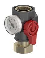
Combination valves with thermometer, range 5/80 °C. Red mark facilitates the assignment of "flow line" and function test through the owner/operator of the system.
System connection G1 femalewith metal thread at heating system end for rapid, reliable mounting to the heating circuit.
Well-designed wall bracket with adjustable wall istance for rapid and easy mounting.
Virtually any standard pump can be installed without refitting of the heat insulation.
Modular, compact heat insulation with label field for heating circuit assignment in the removable cover. Ventilation openings ensure optimum aste heat dissipation.
Maximum flexibility right up to the last minute on the construction site thanks to a robust mixer with adjustable flow coefficient Kvs (3.2 to 5.2) and a simple concept for right/left conversion by swapping the position of the blind plug.
Snap on – done. New actuator with ProClick adapter system for lightning-fast mounting to the mixer without tools.
Pipes with separate heat insulation
Polymer heating pump assembly
PrimoTherm® C 130-1 DN 20
Application
Description
■ Pre-assembled, tightness-tested and heat-insulated assembly
■ Modular system with flow at left or right
■ Easy and fast installation
■ With high-efficiency pump class A
Heating pump assembly for use in non-mixed heating circuits, specially for storage tank charging. It connects the heating boiler and the pipe system.
Complete, pre-assembled and tightness-tested heating pump assembly made of high-grade polymer material with all required functional components, form-fit heat insulation and wall mounting unit.
The flow line consists of:
■ Shut-off valve with thermometer holder (red handle)
■ Thermometer flow (5 to 80 °C)
■ Plastic pipe for length compensation
Suitable for circulation pumps DN 20 with G1 x 130 mm
The return line consists of:
■ Shut-off valve with thermometer holder (black handle)
■ Thermometer return (5 to 80°C)
■ Gravity brake
■ Plastic pipe for length compensation pump / mixer
Technical specifications Axis distance
90 mm
System connections
Boiler G1 male / heating circuit G1 female
Operating temperature range
Medium: Max. 60 °C at 6 bar or max. 70 °C at 5 bar or max. 90 °C at 3 bar
Flow coeffi cient Kvs
5.7 m3/h
Heat insulation
Polypropylene EPP
Dimensions
W x H x D: 189 x 335 x 240 mm
Material
Polymer and brass
Polymer heating pump assembly
PrimoTherm® C 130-1 DN 20
Dimensions (mm)
cations
Polymer heating pump assembly
PrimoTherm® C 130-2 DN 20 KVS Vario
Application
■ Pre-assembled, tightness-tested and heat-insulated assembly
■ Robust mixer with adjustable flow coefficient Kvs from 3.2 to 5.2 m3/h
■ Adaptation of flow coefficient Kvs also possible during operation (under system pressure)
Description
Technical specifications
Heating pump assembly for use in mixed heating circuits. With the 3-way mixer and the actuator, the flow temperature can be adjusted to a desired temperature by adding water from the return. The new mixer with adjustable flow coefficient Kvs offers the HVAC professional maximum flexibility in adapting the system to individual control requirements. This way, a great variety of mixer/pump assemblies can be covered with a single version.
Complete, pre-assembled and tightness-tested heating pump assembly made of high-grade polymer materials with all required functional components, form-fit heat insulation.
The flow line consists of:
■ Shut-off valve with thermometer holder (red handle)
■ Thermometer flow (5 to 80 °C)
■ 3-way mixing valve ARV KVS Vario with adjustable flow coefficient Kvs and ProClick adapter system
■ Maintenance-free, silent actuator ARM 343 (6 Nm, 120 s, AC 230 V) with 0/90° angle of rotation, indication for direction of rotation, selector key "Manual/Automatic Mode" and ProClick adapter system
■ Sensor clip for connection of a flow line sensor with Ø 6 mm Suitable for circulation pumps DN 20 mit G1 x 130 mm.
The return line consists of:
■ Shut-off valve with thermometer holder (black handle)
■ Thermometer return (5 to 80 °C)
■ Gravity brake
■ Plastic piece for length compensation pump / mixer
Axis distance
90 mm
System connections
Boiler G1 male / heating circuit G1 female
Operating temperature range
Medium: Max. 60 °C at 6 bar or max. 70 °C at 5 bar or max. 90 °C at 3 bar
Flow coeffi cient Kvs
Adjustable: 3.2 (3.5) – 3.75 (4.5) – 4.6 (7) –
5.0 (8.5) – 5.2 (9) m3/h () = value adjusted at mixing valve
Leak rate mixing valve KVS Vario
< 0.1 % of flow coefficient Kvs (up to Δp 0.5 bar < 0.2 % of flow coefficient Kvs)
Heat insulation
Polypropylene EPP
Dimensions
W x H x D: 189 x 335 x 240 mm
Material
Polymer and brass
Polymer heating pump assembly
PrimoTherm®
C 130-2 DN 20 KVS Vario
Dimensions (mm)
PrimoTherm® C130-2 with AFRISO pump
Technical
fications
Product highlight: 3-way mixing valves ARV (Vario)
The flow coefficient is key in rating hot water heating systems and providing the right amount of heat at the radiators. Mixing valves in installations must be correctly rated before they are mounted and adjusted to the required flow coefficient Kvs of the system. If
a selection error is made or the system is modified at a later point in time (for example, extended), the existing valve is usually no longer usable. If the flow coefficient Kvs is only estimated, the system will not operate in an efficient way.
Mixer housing made of brass, with robust, glass-fibre reinforced plate at the rear for adjustment of flow coefficient Kvs.
Fast and easy conversion bypass to connection at the right.
Adapter to attach the AFRISO ARM ProClick actuator at the correct position without tools.
Advantages – your benefi ts
Easy adjustment of flow coefficient Kvs with adjustment lever at the rear of the mixer.
Non-slip rotary knob with double-sided scale, position indication in manual mode via limiting ring with mark.
■ A mixer for all cases: Simply set the required flow coefficient Kvs without draining the system
■ No incorrect rating thanks to optimum adaptation to the control requirements of the system. This allows for:
Smaller volume jump Vmin / smaller minimum controllable power Q min
Higher valve authority PV (pressure ratio between mixer and pipe system with all consumers connected)
Complete use of mixer control range (0–100 %)
Improved controllability: No cycles, no flow noise
Positive effects on hydraulic balancing: Power required to heat the heating surfaces is available and can be used
■ Long-lasting service life: Low torque for increased service life of actuator
■ Reduces number of versions and warehousing efforts for mixers and pump assemblies
3-/4-way mixing valves ARV (Vario)
■ For distribution and mixing
■ 3-way mixing valve with adjustable flow coefficient Kvs
■ Low torque for increased service life of actuator
■ ProClick adapter system for motor mounting without tools
Application
Description
Technical specifications
Universal mixing application in water-based heating and cooling systems (radiators, panel heating systems). The 3-way mixer can also be used as a distribution or zone mixer. Suitable for water and water/ glycol mixtures with up to 50 % glycol. Not suitable for drinking water.
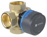
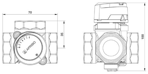
Compact, low-loss 3-way or 4-way mixing valves with brass base and easy-to-handle rotary knob made of high-strength plastic. The rotary knob with scale allows for easy and accurate manual adjustment of the mixing valve. The elevated mark allows for fast position determination. With dual scale "0 to 10" for horizontal installation and "10 to 0" for vertical installation for maximum flexibility.
3-way mixing valve for distribution and mixing: The desired flow temperature is obtained via the precise mixing ratio of hot boiler water and cold water from the return line.
4-way mixing valve for dual mixing. The return temperature to the boiler can be high in order to avoid corrosion damage, for example.
The mixing valves are easy to automate with the AFRISO actuators. The AFRISO ProClick adapter system allows for hassle-free mounting of the motor to the mixing valve without tools.
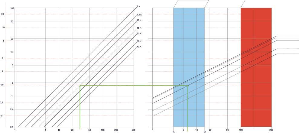
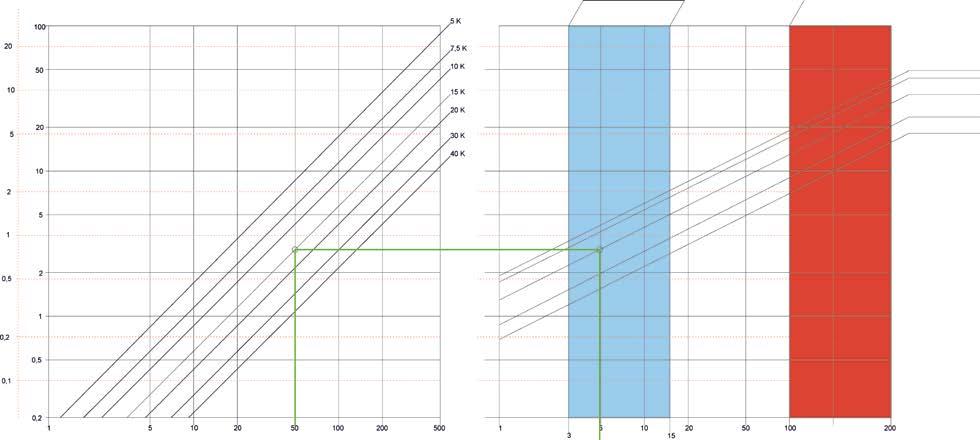
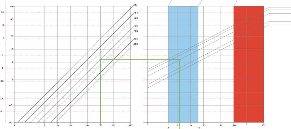
3. Point of intersection in the centre of the optimum range 3–15 kPa
4. Read adjustment value: Kvs 13 (in m³/h at a differential pressure of 1 bar)
Example:
1. Power: 100 kW
2. Temperature spread: 15 K
3. Point of intersection in the centre of the optimum range 3–15 kPa
4. Read adjustment value: Kvs 25 intermediate setting (in m³/h at a differential pressure of 1 bar)
3-/4-way mixing valves ARV (Vario)
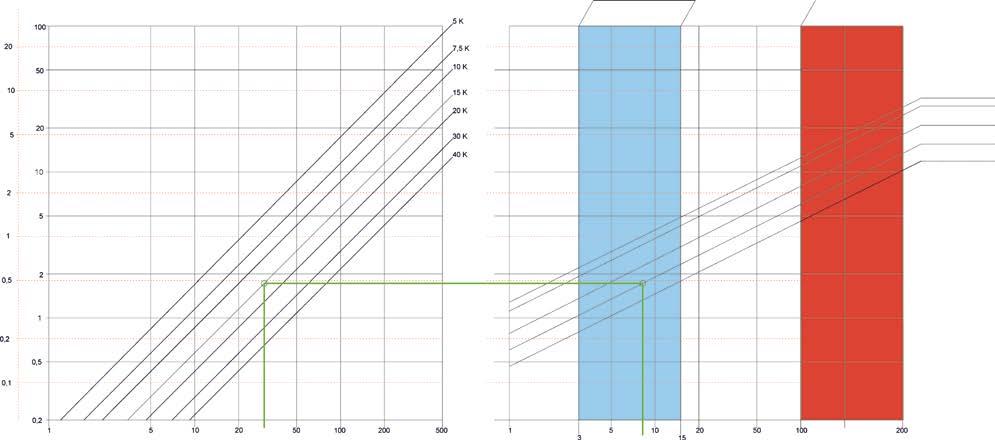
Adjustment values fl ow coeffi cient Kvs DN 50
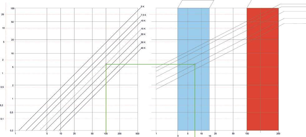
Example:
1. Power: 100 kW
2. Temperature spread: 15 K
3. Point of intersection in the centre of the optimum range 3–15 kPa
4. Read adjustment value: Kvs 22 (in m³/h at a differential pressure of 1 bar)
Heating pump assembly PrimoTherm® K 180 KVS Vario, short design
Combination valves with thermometer in the hand wheel, range 0/120 °C. Red/blue mark facilitates the assignment of "supply/return" and function test through the owner/operator of the system. Additional temperature probes (for example, PT 100) can be integrated behind the ball valve.
System connection G1 female for rapid mounting to the heating circuit.
System connection G1½ male for fast mounting to the boiler flow/return by means of flange and union nut. Suitable for boiler manifold KSV and heat source manifold HSM.
Virtually any standard pump can be installed without refitting of the heat insulation.
Snap on – done. New actuator with ProClick adapter system for lightning-fast mounting to the mixer without tools.
High-grade, robust mixer with adjustable flow coefficient Kvs (2.5 to 12) for maximum flexibility all the way to the construction site.
Integrated adjustable gravity brake.
Modular system with pump and return line left or right.
Easy designation of the heating circuits by means of enclosed pictograms.
MADEIN
Heating pump assembly PrimoTherm® K 180-1 DN 25
Pre-assembled, tightness-tested and heatinsulated assembly (complies with German Energy Saving Regulation)
Modular system with flow at left or right Easy and fast installation
Available with high energy efficiency pumps
class A (Wilo, Grundfos or AFRISO)
Application
Description
Technical specifications
Option
Heating pump assembly for use in non-mixed heating circuits, specially for storage tank charging. It connects the heating boiler and the pipe system.
Comact, pre-assembled and tightness-tested heating pump assembly with all required functional components, form-fit heat insulation (complies with German Energy Saving Regulation) and wall mounting unit. Adhesive labels with pictograms allow for easy designation of the heating circuits.
The flow line consists of:
■ Combination valve with thermometer in the hand wheel (red mark, range 0/120 °C)
■ Ball valve below the pump
■ System connection G1½ male (boiler), G1 female (heating circuit)
Suitable for pumps DN 25 with G1½ x 180 mm.
The return line consists of:
■ Combination valve with gravity brake, thermometer in the handle (blue mark, range 0/120 °C)
■ Pipe for length compensation with screw connection
■ System connection G1½ male (boiler), G1 female (heating circuit)
Axis distance
125 mm
System connections
Boiler G1½ males, heating circuit G1 female
Operating temperature range
Medium: T max = 95 °C, short-term 120 °C
System pressure
Max. 10 bar
■ Other circulation pumps
Flow coeffi cient Kvs 7.6 m3/h
Heat insulation
Polypropylene EPP
Dimensions
W x H x D: 248 x 400 x 155 mm
Heating pump assembly
PrimoTherm®
K 180-1 DN 25
Dimensions (mm)
PrimoTherm® K 180-1 with Wilo pump
Technical specifications
circulation pumps
Length 180 mm
Degree of protection IP 44
Operating modes / power levels
PP (constant volume flow)
CP (constant pressure)
CC (constant speed of rotation)
Supply voltage AC 230 V, 50 Hz
Energy effi ciency class ≤ 0.20
Heating pump assembly
PrimoTherm® K 180-2 DN 25
■ Pre-assembled, tightness-tested and heat-insulated assembly
■ With high-grade, robust mixer
■ Version with adjustable flow coefficient Kvs from 2.5 to 12 m3/h: Adjustment also possible during operation (under pressure) at any time
■ Available with high energy efficiency pumps class A (Wilo, Grundfos or AFRISO)
Application
Description
Technical specifications
Heating pump assembly for use in mixed heating circuits. With the 3-way mixer and the actuator, the flow temperature can be adjusted to a desired temperature by adding water from the return. The mixer version with adjustable flow coefficient Kvs offers maximum flexibility in adapting the system to individual control requirements. The flow coefficient Kvs can be modified at any later point in time, even if the system is under pressure. This way, a great variety of mixer/pump assemblies can be covered with a single version.
Comact, pre-assembled and tightness-tested heating pump assembly with all required functional components, form-fit heat insulation (complies with German Energy Saving Regulation) and wall mounting unit. Adhesive labels with pictograms allow for easy designation.
The flow line consists of:
■ Combination valve with thermometer in the hand wheel (red mark, range 0/120 °C)
■ 3-way mixing valve with ProClick adapter system, either ARV 325 with flow coefficient Kvs 12 m3/h or KVS Vario with adjustable flow coefficient Kvs
■ Maintenance-free, silent actuator ARM 343 (6 Nm, 120 s, AC 230 V) with 0/90° angle of rotation, indication for direction of rotation, selector key "Manual/Automatic Mode" and ProClick adapter system
■ System connection G1½ male (boiler), G1 female (heating circuit) Suitable for pumps DN 25 with G1½ x 180 mm.
The return line consists of:
■ Combination valve with gravity brake, thermometer in the handle (blue mark, range 0/120 °C)
■ Pipe for length compensation as T piece for mixer connection with screw connection for system connection
■ System connection G1½ male (boiler), G1 female (heating circuit)
Leak rate mixing valve ARV 325 Kvs Vario < 0.1 % of value of flow coefficient Kvs (up to Δp 0.5 bar < 0.2 % of value of flow coefficient Kvs)
Heat insulation
Polypropylene EPP
Dimensions
W x H x D: 248 x 400 x 155 mm
Heating pump assembly
PrimoTherm® K 180-2 DN 25
Dimensions (mm) DG: G, PG: 2
PrimoTherm® K 180-2 with Wilo pump
PrimoTherm
Operating modes / power levels
PWM-A x/4 -/-
PWM-C x/4 -/-
PP (constant volume flow) x/3 x/3
CP (constant pressure) x/3 x/3
CC (constant speed of rotation) x/3 x/3
Heat pump service combination
AHS 500 / 560
■ Filling and flushing unit with screwed hose connections
■ Separation via magnetite sludge separator or filter with stainless steel sieve (high temperature version)
■ Integrated shut-off valves
■ Large flow range: 5–42 l/min
Application
Description
Function
For integration into closed heating systems and manifold systems, independent of the heat generator.
As per VDI 2035, heating systems must be filled with treated heating circuit water. In addition, high-performance heat transfer media and/or antifreeze agents are increasingly being used. Regardless of whether a new heating system is installed or an existing one upgraded, flushing the system is essential to remove contamination and ensure efficient operation. This requires a filling and flushing unit to be installed. For subsequent operation, the installation of a magnetite sludge separator is state of the art to ensure separation of contaminants such as magnetite on an ongoing basis. It is advisable to install shut-off elements to allow for easy cleaning the magnetite sludge separator. Practically all heat generators already feature electronic displays for the flow rate and system pressure. Nevertheless, the installation of a mechanical flow meter and a classic pressure gauge is helpful in monitoring the initial filling of the system and in checking the flow rate and system pressure during subsequent service work. Installing these components individually can lead to space problems. This often results in important fittings being installed in a poorly accessible location, which makes them difficult to operate later on. Installing, sealing and insulating the individual components requires a great deal of effort. A resulting additional pressure loss in the complete system can be avoided by using AHS.
The heat pump service combination combines all the functions of the individual components described in a compact unit and offers a practical solution covering the entire life cycle of the system:
■ During installation or maintenance, the combination can be used for flushing and filling of the system. The supplied hose connections are screwed on instead of the separator or filter.
■ During operation, the connections are used to accommodate the sludge separator or filter. Thanks to the integrated ball valves, both connections can be reliably closed for conversion, dismantling and cleaning. The flow meter provides information on the actual flow rate. An optional pressure gauge can be fitted from both sides, depending on the mounting position, to allow a quick visual inspection
The form-fit thermal insulation pieces (accessories) optimally reduce heat losses and save time during installation. The AHS 500 version with a brass filter with stainless steel sieve is available for high system temperatures.
Mounting of hose connections and shutoff units for system filling or flushing
High temperature version AHS 500 up to 160 °C
Heat pump service combination
Technical specifications
Materials
Housing AHS 500: Brass
Housing AHS 560: Brass/plastic (PA66 GF 30)
Seals: EPDM
Filter sieve:: Stainless steel
Connection pieces: Brass
Heat insulation: XLPE
Operating pressure
AHS 500: Max. 10 bar
AHS 560: Max. 3 bar
Flow coeffi cients Kvs
AHS 500: 6.5 m3/h
AHS 560: 6.9 m3/h
Operating temperature range
AHS 500: Max. 120 °C (short term 160 °C)
AHS 560: Max. 90 °C
Connection G1 female
Filter mesh size
AHS 500: 500 μm
AHS 560: 500 and 800 μm
Magnetite insert AHS 560: Neodymium 1.4 T (14,000 Gs)
Mounting position
Any, separator head of AHS 560 can be rotated
Mounting place
Preferably in return line to heat generator
Accessories
■ Form-fit heat insulation
■ Pressure gauge
AHS 500
AHS 560
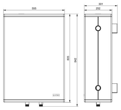
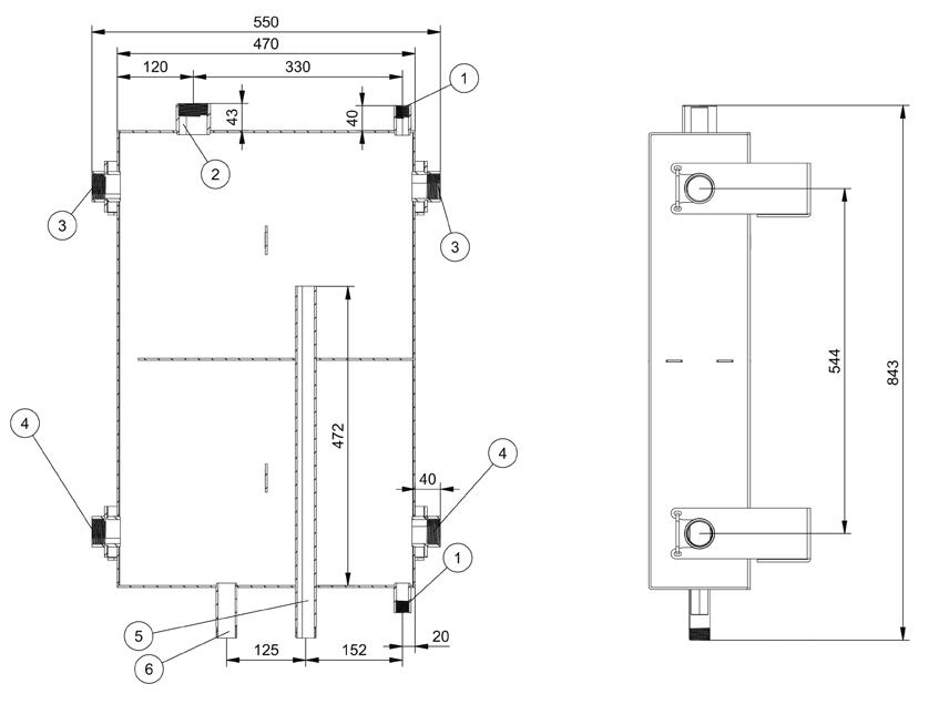
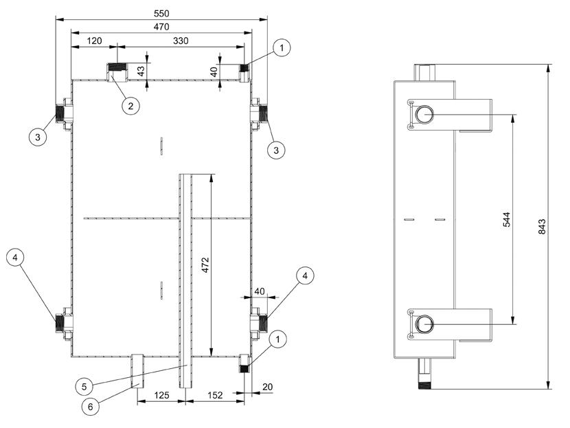
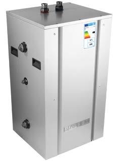
Buffer tank ABT 50
■ 50 litres storage capacity
■ Space-saving, wall-mounted installation, versatile connection system
■ Integration of 2 heat generators possible
■ Mounting option for electric heating element
■ Optimum stratification thanks to heat conduction system
Application
Description
Technical specifications
Buffer tank for hot or cold storage in sealed heating systems as per EN 12828. The buffer tank allows for the integration of up to two heat generators and an additional electric heating element. The connection to the heating circuit operates as a hydraulic separator and is designed for direct connection of the AFRISO boiler manifolds KSV or the pump assemblies PrimoTherm®. Operation with a heat pump ensures a sufficient volume flow and keeps the heat pump from intermittent operation due to a lack of system volume. In addition, the buffer tank ensures that there is sufficient heat capacity for defrosting the outdoor unit.
Compact buffer tank consisting of a rectangular steel tank with a storage capacity of 50 litres and an external, form-fit heat insulation. A baffle plate in the tank ensures a stratified temperature distribution in the tank to allow for controlled mixing of the flow and return. Lateral connections - either to the right or to the left - make it easy to adapt the buffer tank to the conditions on site. The buffer tank is mounted with two wall mounting brackets. A drilling template is provided in the package to facilitate installation.
Series ABT buffer tanks comply with the EU Regulation 812/2013 und der EU Regulation 814/2013.
Storage capacity
50 litres
Connections
Thermal generator: 4 x G1¼ female
Heat/cooling circuit: 2 x screw connection G1 female x G1½ union nut
Heating element: G1½ female
Operating pressure
Max. 3 bar
Medium
Heating circuit water or water/glycol mixture
Operating temperature range
Ambient: 0/60 °C
Medium: 5/0 °C
Material
Buffer tank: Sheet steel (4 mm)
Heat insulation: Polypropylene EPP
Weight
30 kg
Dimensions (W x H x D)
842 x 555 x 252 mm
Length of heating element Max. 360 mm
Energy class (as per EU Regulation 812/2013) C
Heat losses
56.4 W
Scope of delivery
■ 2 x screw connection G1 female x G1½ union nut for heating circuit
■ 1 x closing plug G1½ for connection heating element
■ 2 x closing plug G1¼ for thermal source connection
■ 1 x closing plug G½ for quick air vent connection
■ 1 x quick air vent with mounting valve R½
■ 2 x wall mounting brackets
■ Drilling template
DG: G, PG: 3
no. Buffer tank ABT
Connection of flow/return either from the right or from the left
Buffer tank ABT 50
Dimensions (mm)
Dimensions with heat insulation
Dimensions without heat insulation
① Connection G½
② Connection for heating element G1½
③ Flow heat generator G1¼
④ Return heat generator G1¼
⑤ Heating circuit flow 1"
⑥ Heating circuit return 1"
Buffer tank ABT 160
■ 160 litres storage capacity
■ Floor-standing version, versatile connection system
■ Integration of 2 heat generators possible
■ Mounting option for electric heating element
■ Optimum stratification thanks to heat conduction system
Application
Description
Technical specifications
Buffer tank for hot or cold storage in sealed heating systems as per EN 12828. The buffer tank allows for the integration of up to two heat generators and an additional electric heating element. The connection to the heating circuit operates as a hydraulic separator and is designed for direct connection of the AFRISO boiler manifolds KSV or the pump assemblies PrimoTherm®. Operation with a heat pump ensures a sufficient volume flow and keeps the heat pump from intermittent operation due to a lack of system volume. In addition, the buffer tank ensures that there is sufficient heat capacity for defrosting the outdoor unit.
Compact buffer tank consisting of a rectangular steel tank with a storage capacity of 160 litres, foamed heat insulation and outer casing made of sheet metal. A baffle plate in the tank ensures a stratified temperature distribution in the tank to allow for controlled mixing of the flow and return. Lateral connections – either to the right or to the left – make it easy to adapt the buffer tank to the conditions on site. The floor-standing buffer tank is equipped with levelling feet to compensate for uneven floors.
Series ABT buffer tanks comply with the EU Regulation 812/2013 und der EU Regulation 814/2013.
Storage capacity
160 litres
Connections
Thermal generator: 4 x G1¼ female
Heat/cooling circuit, boiler manifold: 2 x screw connection
G1 female x G1½ union nut
Heating element: G1½ female
Operating pressure
Max. 3 bar
Medium
Heating circuit water or water/glycol mixture
(glycol max. 50 %)
Operating temperature range
Ambient: 0/60 °C
Medium: 5/90 °C
Material
Buffer tank: Sheet steel (4 mm)
Heat insulation: Polypropylene EPP
Weight
103 kg
Dimensions (W x H x D)
1,055 x 550 x 500 mm
Possible length of heating element
Max. 480 mm
Heat losses
57.1 W
Scope of delivery
■ 2 x screw connection G1 female x G1½ union nut for heating circuit
■ 1 x boiler filling and drain valve KFE G½
■ 3 x closing plug G1½ for thermal source and heating element
■ 1 x pocket for temperature probe G ½
■ 1 x closing plug G½ for connection temperature sensor sleeve
Buffer tank ABT 160
① Flow
② Pocket for
③ Return
④ Heating circuit flow
⑤ Heating circuit return
⑥ Connection for heating element
⑦ Boiler filling and drain valve KFE
Zone valve AZV
■ Robust brass version
■ Fully tight
■ Intuitive position indicator using a coloured traffic light system
■ Low pressure loss, ideal for large water volumes
■ Esay integration into heat pumps or hydraulic systems
■ Maintenance-free
Application Description
Technical
specifications
For integration into heat pumps or hydraulic systems. AZV can be used, for example, to switch between the operating modes "heating" and "cooling" or "heating" and "service water heating" as well as for switching over in water storage tank applications and is also suitable for shutting off. Different housing versions allow the zone valve to be customised to suit the application and location. Suitable for water and water/glycol mixtures with up to 50 % glycol.
Zone valve consisting of valve unit and electrical drive. The proven, robust design results in complete tightness with low pressure loss. A position indicator with a coloured traffic light system intuitively signals the switching state of the valve. The direction of flow of the valve in the rest position can be changed while the valve is installed, without the necessity to open the water circuit.
Manual emergency operation is possible by removing the electric motor and turning the integrated hand wheel.
Valve
Material
Housing: Brass (CW617N)
Seals: EPDM
Connections
See table
Operating pressure
Max. 10 bar
Permissible differential pressure
Max. 2 bar
Setting angle
90°
Medium
Heating circuit water or water/glycol mixture (glycol max. 50 %)
Operating temperature range
Ambient: 0/75 °C
Medium: –20/90 °C
Electrical drive
Housing
Material: Plastic (PC/ABS)
Protection class: II
Degree of protection: IP 54 (EN 60529)
Electrical connection
AMP Superseal 1.5 series 1745082-1
Running time
15 seconds
Power input
< 7 W, in rest position 0 W
Supply voltage
AC 230 V, 50 Hz
Nominal duty type
S3 25 %
Options
■ Drive with other running times
■ Drive with more powerful motor/gear
■ Customised housing geometry
■ Other connections
Zone valve AZV
Motorised actuator for hydraulic balancing MSA 10 DT Ü NC
■ Install and you're done! Dynamic hydraulic balancing all year round
■ First Open function
■ Universal application in existing and new buildings
■ Suitable for heating and cooling
■ Probe position detected automatically, therefore impossible to confuse
Application
Description
Technical specifications
Actuator for automatic hydraulic balancing and energy-saving operation of surface heating systems. Suitable for controlling hot water valves in manifold systems such as the AFRISO heating/cooling system manifold ProCalida® MC, EF, VA and IN. Thanks to valve displacement detection and precise valve control, the actuator can also be used universally on existing manifolds. The adaptive PID control algorithm of the continuous controller controls the flow rate based on the measure flow and return temperatures for hydraulic balancing all year round, even during partial load operation of the heating system.
The actuator is factory-opened (First Open function) so that the stroke valves at the heating circuit manifold remain open during initial commissioning. This facilitates mounting as well as filling and flushing of the system since, at this point in time, the control system is usually not yet operative. The First Open function (FO) is automatically disabled as soon as the actuator is electrically controlled. The FO function can be re-enabled via a reset.
Motorised, actuator with temperature-dependent control, with First Open and Re-Open function, LED indicator and two probe cables. Direct connection to the valve or upper part of the valve with union nut. Control via the supply voltage (230 V / 24 V) of the control terminal bar. Low power consumption, since the motor only requires energy when it actually moves. MSA automatically detects which probe is used as the flow or return probe.
Functions
First-open function (can be re-enabled) and closing point detection by homing movement during initial activation
Operating mode
Closed when de-energised (NC)
Condition as delivered: Open
Control stroke
4.5 mm
Closing dimension / actuating force
10.5 mm / 100–150 N
Connection
Union nut M30 x 1.5 mm
(brass, nickel-plated)
Housing
Upper part: Plastic PA6, white
Bottom part: Plastic PA6, white
Flame retardant
Degree of protection: IP 54
(IEC 60529 / EN 60529)
Cable
2 x 0.75 mm², white, H05
Length: 0.9 m
Temperature probes
Fastening by means of pipe clip, cannot be confused
Cable length 0.4 m
Operating temperature range
Operation (at valve): Max. 50 °C
Storage / transport: –25/+60 °C
Ambient: 0 / 50 °C
Ambient humidity: <85 % r.h., non-condensing
Supply voltage
AC 230 V ±10 % 50–60 Hz
AC / DC 24 V ±20/10 % 50–60 Hz
Power input continuous operation
Version 230 V: < 1 W
Version 24 V: < 0.5 W
Inrush current
30 mA for a maximum of 200 ms
Protection class
III (EN 60730-1 bei 24 V ~/=)
II (EN 60730-1 bei 230 V ~)
Motorised actuator for hydraulic balancing
MSA 10 DT Ü NC
Technical specifications
Dimensions (mm)
CE conformity
EMC Directive (2014/30/EU) Low Voltage
Directive (2014/35/EU)
RoHS Directive (2011/65/EU)
EN 60730-1:2016+A1:2019+A2:2022
EN IEC 60730-2-14:2019+A2:2021
EN 61000-3-3:2013/A2:2021
EN IEC 61000-3-2:2019/A1:2021
EN IEC 63000:2018
Accessories for manifold systems
Quick air vent (option)
The manual air vent can be easily replaced with an automatic quick air vent using a lifting tool, for permanently deaerated system water.
Ball valve (option) Flat-sealing
Flow meters
Flow meter for easy hydraulic balancing of the system. With a range of 0.5–4 l/min and locking as per EN 1264-4. Control valves can be shut off. The sight glass of the flow meter can be cleaned with system pressure present.
Thermometer Ø 40 mm for direct temperature indication in the flow and return lines.
Angular connection set (option) For bottom connection
Pressure gauge RF50 (option)
Boiler filling and drain valve KFE
For indication of the system pressure (0/10 bar).
Can be screwed directly onto the boiler filling and drain valve KFE. Also suitable for tightness test.
Rotatable filling and drain valve for filling, draining or flushing the complete system.
MADEIN
Thermostatic actuator TSA 01 (option) For electronic control of the heating circuits. Ideal for limited space conditions.
Dynamic control valve Vario-DP (option)
Pre-adjustment of the valve allows for automatic control of the water volume per heating circuit (20–340 l/h) and thus for fast, reliable hydraulic balancing. The geometry of valve insert provides protection against unwanted pollution. Flow with shut-off valve instead of flow meter.
Wall bracket
4 polymer brackets with excellent soundabsorbing properties can be snapped into the dovetail guide of the manifold bar – for collision-free installation and flexible distances between flow and return during renovation, installation of large footprint actuators or use of heating circuit pipes up to 20 mm.
Designation labels
Threaded rods
For maximum stability of the manifold bar.
Prefabricated stickers for labelling the individual heating circuits.
Insulating dual-chamber system
Inside with large cross-section for optimum supply of system water to the control circuits, outside with air cushion for superior heat loss limitation. The use of plastic as the base material virtually eliminates condensation.
Sustainable production of the ProCalida MC 1 manifold system in Germany with maximum vertical range of manufacture and the shortest possible transport routes – most of the value added takes place at the headquarters in Güglingen.
Living room
MADEIN GERMANY MADEIN GERMANY
Polymer heating circuit manifold
ProCalida ® MC 1
Application
Also available with dynamic control valve Vario-DP for easy hydraulic balancing!
Dual-chamber system for optimum heat loss limitation
Large cross section for optimum supply of the control circuits
Flow meter can be cleaned with system pressure present
Pre-assembled, tightness-tested and ready to be connected
Manifold system for surface heating systems and cooling systems. For distribution of heating and cooling circuit water as per VDI 2035 or of water/glycol mixtures in sealed systems. Suitable for 2–12 heating/cooling circuits.
Robust, very short heating or cooling circuit manifold made of high-grade polymer materials, with up to 12 heating circuits. Return with stroke valves for actuators. Return valves with dual O ring seal at the valve axis for particularly long running times with optimum sealing. Valve disc with O ring seal for permanently reliable closing of the control circuits.
Flow with flow meters that can be shut off. Control range flow meter 0.5 to 4 l/min with locking as per EN 1264-4. The valves can be shut off and regulated for hydraulic balancing of wall or underfloor heating systems. When the system is shut off, the pre-adjustment is not lost for compliance with EN 1264-4.
Windows can be cleaned and replaced with system pressure present. Main connection with union nut G1. With filling and drain valve, manual vent and thermometer.
Quick air vent can be fitted using a lifting tool. Connection by means of angular connection pieces and/or ball valve G1 adapted to the manifold. With dovetail guide at both ends for fast snap-in mounting and horizontal movement of the wall bracket.
The wall bracket is made of robust polymer material and therefore has excellent sound-absorbing properties.
Suitable for standard manifold cabinets. With adjustable distance between the flow and return bars, for easy, collision-free mounting even in the case of large actuator and heating circuit pipes up to 20 mm. The AFRISO manifold systems are 100 % tightness-tested and function-tested.
Number of heating/cooling circuits
2–12
Medium
Heating circuit water and cooling water as per VDI 2035 (water/glycol mixtures with an admixture of max. 50 %)
Test pressure
Max. 6 bar
Main connection
G1 flat-sealing, with union nut
Connection from the right or from the left
Connection heating/cooling circuit
G¾ male thread, eurocone, suitable for standard compression fittings
Operating temperature range
Medium: –20/+90 °C at 3 bar
–20/+60 °C at 6 bar
Flow coeffi cient Kvs
Flow valve: 1.56 m³/h
Return valve: 1.3 m³/h
Combined: 1.0 m³/h
Flow meters
Can be shut off and regulated, with pre-adjustable adjustment ring
Range: 0.5 to 4 l/min
Mounting position: Any
Accuracy: +/– 10 % water, with reference to the full scale value
Return valves
Mating thread: M 30 x 1.5 mm male thread
Closing force: < 70 N
Closing dimensions: 12 ± 0.6 mm (open position 15 mm)
Suitable for electro-thermostatic actuators TSA 01, 02 and 03 from AFRISO or standard actuators with union nut M 30 x 1.5 mm and closing dimensions between 10.3 and 11.0 mm
Wall bracket
Made of polymer, suitable for standard manifold cabinets, bar distance selectable as required
Options
■ Wall bracket with fixed distance
■ With dynamic control valves Vario-DP in the return
Version SV with shut-off valve
MADEIN GERMANY MADEIN GERMANY
Polymer heating circuit manifold
ProCalida ® MC 1
Types and dimensions (mm)
Version with flow meter (FM)
Dimensions table
MADEIN
Polymer heating circuit manifold
Types and dimensions (mm)
Dimensions table
Polymer heating circuit manifold
Adjustment diagram for version with shut-off valve for calculation the fl ow
Polymer heating circuit manifold
ProCalida ® MC 1
Dynamic control valve – for automatic hydraulic balancing
The version with a dynamic control valve Vario-DP features a shut-off valve in the flow line of the manifold instead of the flow meter.
Advantages – your benefits
Automatic control of water volume per heating circuit
Fast hydraulic balancing
Adjusted flow rate is not exceeded
High reserve due to very wide adjustment range up to 340 l/h
Geometry of valve insert provides protection against unwanted pollution
No additional line fittings required for balancing of the individual stations or floors
Pre-adjustment water volume for control valve Vario-DP
Adjustment table
Preadjustment
Polymer heating circuit manifold
order quantity SV with
Thermostatic actuator TSA-01
Application
Description
Technical specifications
TSA-01 with male thread (part no. 79062) suitable for standard manifolds with female thread M 30 x 1.5 mm.
Integrated stroke indicator
Slim design (Ø 39 mm)
Very low design for limited space conditions
For controlling the hot water valves in radiators or AFRISO distribution manifolds such as ProCalida® MC VA 1C. Actuators convert the electric signal they receive from room thermostats or thermostats with timers into a valve stroke to control the set temperature by means of the flow rate. The actuator is normally closed (NC) and thus immediately ready for automatic operation.
Electro-thermostatic actuator with integrated position indication in the cover window, connection cable and union nut for direct connection to the valve or upper part of the manifold. Closed when de-energised.
Operating mode
Closed when de-energised (NC)
Stroke > 3.2 mm
Integrated indicator in the transparent window
Opening time
5–6 minutes
Closing dimension / actuating force
10.8 mm / approx. 90 N
Connection
Part no. 79061: Union nut M 30 x 1.5 mm
Part no. 79062: Male thread M 30 x 1.5 mm
Housing
Plastic
Degree of protection IP 54 (EN 60730-1)
Colour cover: Transparent
Colour stroke indication: White
Cable
2 x 0.75 mm2, grey, H05
Length: 1 m
Operating temperature range
Operation: Max. 100 °C (at valve)
Storage / transport: –25/+70 °C
Ambient: 0/+50 °C
Relative humidity: < 85 % r.h. non-condensing
Supply voltage AC 230 V
Power input
Approx. 2 W (continuous operation)
Switch on power 32.2 W
Inrush current 140 mA
Protection class II (EN 60730-1)
CE conformity
Low Voltage Directive 2014/35/EU: EN 60730-1 EN 60730-2-14
RoHS Directive 2011/65/EU: EN IEC 63000
EMC Directive 2014/30/EU: EN 60730-1
Dimensions
Part no. 79061 = H x Ø: 57 x 39
Part no. 79062 = H x Ø: 54 x 40
Weight 109 g
Option ■ 24 V version
WB 10
ProCalida® VA 1
ProCalida® MC 1
Thermostatic actuator TSA-01
Dimensions (mm)
TSA-01 with female thread and union nut (part no. 79061)
TSA-01 with male thread (part no. 79062)
Thermostatic actuator TSA 13 Ü NC – normally closed
■ First Open function
■ Manual Re-Open function without power applied
■ Stroke indicator
■ Integrated limit switch for circulation pump
■ Either as 24 V or as 230 V version
Application
Description
For controlling the hot water valves in radiators or AFRISO distribution manifolds such as heating/ cooling circuit manifolds ProCalida® MC, EF, VA and IN. Actuators convert the electrical signal received from room or timer thermostats into a valve stroke to control the set temperature via the flow volume. The actuator is factory-opened (First Open function) so that the stroke valves at the heating circuit manifold remain open during initial commissioning. This facilitates mounting as well as filling and flushing of the system since, at this point in time, the control system is usually not yet operative. The First Open function (FO) is automatically disabled as soon as the actuator is electrically connected and fully closed. The FO function can also be manually deactivated by lifting the stroke indicator with a screwdriver. When the stroke indicator is lifted, the "clip Re-Open" is “ relieved and disables the FO function. For servicing, the factory setting "open" of the actuator can be restored manually via the clip without power having to be applied. To do so, lift the stroke indicator with a screwdriver until the clip can be pushed below the stroke indicator. The pre-load of the stroke indicator keeps the clip in position and the FO function is active again.
Electro-thermostatic actuator with First Open and Re-Open functions, position indication, limit switch, connection cable and union nut for direct connection to the valve or upper part of the valve. TSA 13 can be used to switch off the pump via the integrated limit switch when all valves are closed. Closed when de-energised; available as 24 V or as 230 V version. Any mounting position.
Technical specifications
Functions
First Open and Re-Open functions (adjustable via "clip re-open")
Operating mode
Closed when de-energised (NC)
Condition as delivered: Open
Maximum stroke / running time
4.5 mm / 3.5 min at 230 V
4.5 mm / 4.5 min at 24 V
Closing dimension / actuating force
10.8 mm / 110 N
Connection
Union nut M30 x 1.5 mm
Switching output
1 voltage-free, normally open contact
Housing
Plastic PA 6, flame retardant
Degree of protection IP 54 (EN 60730-1)
Colour lower part: White
Colour cap: White
Colour stroke indicator: Yellow
Customer-specific logo
Cable
4 x 0.75 mm², white, H05
Length: 1 m
Operating temperature range
Operating temperature at valve: Max. 100 °C
Storage and transport temperature: –25/+70 °C
Ambient temperature: 0 / 50 °C
Ambient humidity: <85 % r.h., no condensation
Supply voltage
Operating voltage AC 24 V
Operating
Power input continuous operation
1.6 W (24 V /=)
1.7 W (230 V )
Switch on power
4.8 W (24 V /=)
34.5 W (230 V )
Inrush current
200 mA (24 V /=)
150 mA (230 V )
Contact rating
AC/DC 24 V, max. 6 (2) A
AC 230 V, max. 6 (2) A
Protection class
III (EN 60730-1 at 24 V /=)
II (EN 60730-1 at 230 V ~)
Thermostatic actuator TSA 13 Ü NC – normally closed
Technical specifications
Dimensions (mm)
CE conformity
Low Voltage Directive
2014/35/EU: EN 60730-1 EN 60730-2-14
RoHS Directive 2011/65/EU: EN IEC 63000
EMC Directive 2014/30/EU: EN 60730-1
Dimensions H x W x L: 68 x 40 x 56 mm
Weight 165 g
Activation of Re-Open function
Mounting spacer (option)
① Lift sleeve push clip in direction of arrow ② Relieve sleeve, clip is tensioned
Continuous thermostatic actuator TSA 14 Ü NC – normally closed
■ First Open function
■ Manual Re-Open function without power applied
■ Stroke indicator
■ Supply voltage 24 V
■ Control voltage 2–10 V
■ Continuous control and monitoring of stroke position
Application
Description
Connection diagram
Technical specifications
For continuous control of hot water valves in heating and cooling circuits for highly demanding control tasks in building control systems. The actuator converts the electrical signal ( 2–10 V) received from a room thermostat or a building control system into a valve stroke. Depending on the version, the supply voltage is DC (direct voltage) or AC (alternating voltage).
The actuator is factory-opened (First Open function) so that the vales at the heating circuit manifold remain open during initial commissioning. This facilitates mounting as well as filling and flushing of the system since, at this point in time, the control system is usually not yet operative. The First Open function (FO) is automatically disabled as soon as the actuator is electrically connected and fully closed. The FO function can also be manually deactivated by lifting the stroke indicator with a screwdriver. When the stroke indicator is lifted, the "clip Re-Open" is relieved and disables the FO function. For servicing, the factory setting "open" of the actuator can be restored manually via the clip without power having to be applied. To do so, lift the stroke indicator with a screwdriver until the clip can be pushed below the stroke indicator. The pre-load of the stroke indicator keeps the clip in position and the FO function is active again.
Electro-thermostatic actuator with continuous control, with First Open and Re-Open functions, position indicator and control line 2–10 V. 2–10 V control line and union nut for direct connection to the valve or upper part of the valve. With spacer for closing dimension compensation and optimum adaptation to the valve to be controlled. Detection of closing dimension during initial commissioning.
Functions
First Open and Re-Open functions (adjustable via "clip re-open")
Automatic deactivation of the first-open function and closing point detection by homing movement during commissioning
Operating mode
Closed when de-energised (NC)
Condition as delivered: Open
Control stroke
4.0 mm
Closing dimension / actuating force
10.8 mm / 110 N
Connection
Union nut
M30 x 1.5 mm
Plastic PA 6, flame retardant
Housing
Plastic PA 6, flame retardant
Degree of protection IP 54 (EN 60730-1)
Colour lower part: White
Colour cap: White
Colour stroke indicator: Yellow
Cable
3 x 0.25 mm², white Length: 1 m
Operating temperature range
Operating temperature at valve: Max. 100 °C
Storage and transport temperature: –25/+70 °C
Ambient temperature: 0/50 °C
Ambient humidity: <85 % r.h., non-condensing
Supply voltage
Operating voltage AC 24 V ~ ±20 % 50–60 Hz
Operating voltage DC 24 V = ±20 %
Control voltage
Standard: 2–10 V (DC)
Power input continuous operation
1.1 W (24 V /=)
Switch on power
4.8 W (24 V /=)
Inrush current
200 mA (24 V /=)
Protection class III (EN 60730-1 at 24 V ~/=)
MADEIN
Continuous thermostatic actuator
Continuous thermostatic actuator
TSA 14 Ü NC – normally closed
Technical specifications
CE conformity
Low Voltage Directive
2014/35/EU: EN 60730-1 EN 60730-2-14
RoHS Directive 2011/65/EU: EN IEC 63000
EMC Directive 2014/30/EU: EN 60730-1
Dimensions (mm) and electrical connections
■ Other control strokes ■ Other voltage ranges ■ Union nut M30 x 1.5 mm (brass, nickel-plated)
Activation of Re-Open function
Mounting of spacer
Room thermostat RT 10 D 230 C
Application
Description
Technical specifications
■ Easy mounting on standard in-wall switch boxes
■ 230 V version
■ Clear display with heating, cooling and request indicator
■ Adjustable time programs
■ Heating and cooling
Determination of the actual ambient temperature and adjustment of the reference value for the room temperature for use in water-based underfloor heating systems, in heating and cooling applications.
The room thermostat RT 10 D 230 C is used in water-based underfloor heating systems in conjunction with thermostatic actuators and/or controller terminal bars (e.g. CosiTherm® Basic WB 10 D-8-230 and WB 01 D). Each room thermostat measures the actual ambient temperature and switches the output to obtain the required reference temperature. The reference value for the room temperature is adjusted by means of the keys. The actual temperature in rooms with an underfloor heating system is compared to the reference temperature on an ongoing basis. In addition to the reference temperature, you can store timer programs (e.g. Day/Night/Heating/Cooling). The display shows values such as temperature, time, heating and cooling mode. Switching between heating and cooling is done either directly on the device or centrally via a potential-free collective contact.
An additional NTC temperature probe can be connected to the RT room thermostat (not included in scope of delivery) which can be used as a floor temperature sensor or as an alternative room temperature sensor, depending on the configuration. Frost protection functions and screed temperature protection functions can also be configured.
Programs
For heating and cooling
Adjustable for 5 + 2 or 6 + 1 days or 7 days
Operating temperature range
Ambient/storage: 5/60 °C
Temperature adjustment range
5/35 °C
Accuracy: ±0.5 K
Supply voltage
AC 230 V
Contact rating
Max. 3 A 250 V AC
Housing
Plastic, PC
Colour: White (RAL 9003), black (RAL 9004)
Degree of protection: IP 20 (EN 60529)
Weight 165 g
Scope of delivery
■ RT 10 D 230 C
Room thermostat RT 10 D 230 C
Types and dimensions (mm)
Dimensions (mm)
Connection diagram
Bourdon tube pressure gauge with reed contact nominal size 63
Application
Technical specifications
■ Wetted parts and movement made of stainless steel
■ Safety housing S3 as per EN 837-1 (blow-out)
■ Switching contact manually adjustable over entire display range
For corrosive gaseous and liquid media which are not highly viscous and do not crystallise. For measuring in areas with limited space. Suitable for use in hazardous areas under specific conditions (see operating instructions).
Type
D 4
Nominal size
63
Accuracy class (EN 837-1/6)
1.6
Ranges (EN 837-1/5)
–1/+1.5 to –1/+15 bar
0/2.5 to 0/400 bar
Application area
Static load: ¾ x full scale value
Dynamic load: ²⁄³ x full scale value
Short-term: Full scale value
Contact type
Reed contact (RK)
Standard version Connection
Stainless steel 316 L, bottom or cente back, bottom back G¼ B – SW14 (EN 837-1/7.3)
Electrical connection
Cable gland
Cable length: 2 m
Measuring element
Bourdon tube, stainless steel 316 Ti/316 L
≤ 60 "C" type tube
> 60 bar helical tube
Movement
Stainless steel
Dial
Aluminium, white
Dial marking black
Options
■ Wetted parts oil-free and grease-free
■ Other process connections
■ Various cable lengths
Minimum range 2.5 bar
Operating temperature range
Medium: T max = +150 °C
T max = +80 °C (ATEX)
Ambient: Tmin = –20 °C T max = +60 °C
Temperature performance
Indication error when the temperature of the measuring system deviates from the normal temperature of 20 °C: rising temperature approx. ±0.4 %/10 K falling temperature approx. ±0.4 %/10 K of full scale value
Degree of protection IP 32 (EN 60529)
Pointer
Aluminium, black
Housing
Stainless steel 304, safety housing S3 as per EN 837-1 with rear blow-out and solid baffle wall
Bayonet type bezel
Stainless steel 304
Window
Laminated safety glass
■ Throttle screw
■ Special scales
Bourdon tube pressure gauge with reed contact nominal size 63
Housing types and dimensions (mm)
Bottom connection
Centre back connection
MADEIN GERMANY MADEIN GERMANY
Pressure transducers DMU 13 Vario with local display
Application
Description
Technical specifications
Additional data transducer
■ Robust stainless steel housing
■ High-precision measurements with integrated transducer
■ Mechanical, power-independent local display
■ Zero correction via magnet
Options
DMU 13 Vario with cooling element and chemical seal
For pressure measurements with a power-independent local display in combination with an electrical output signal.
The DMU 13 Vario pressure transducers consist of a mechanical Bourdon tube measuring element and a piezo-resistive polysilicon thin-film measuring cell. The Bourdon tube measuring element is used to provide an easy-to-read analogue local display. The display is power-independent. Due to the integrated pressure transducer, high-precision measurement in parallel is possible. A standardised current output is available for signal transmission and recording of measured data. The robust stainless steel housing has a solid baffle wall and blow out. The zero point of the electronic sensor can be corrected from the outside via a permanent magnet after voltage has been applied and within a given time window.
Nominal size
100
Measuring accuracy
Pressure gauge: Class 1.0 (EN 837-1/6)
Transducer: Deviation from the characteristic curve according to IEC 60770 – limit point calibration (non-linearity, hysteresis, repeatability):
< ± 0.3 % FSO
Measuring ranges
Relative pressure: –1/0 bar, 0/0.6 bis 0/400 bar
Application area
Static load: Full scale value
Dynamic load:
0.9 x full scale value
Short term: 1.3 x full scale value
Operating temperature range
Medium: –10/+100 °C
Ambient: –10/+60 °C
Storage: –10/+70 °C
Output signal/supply voltage
4–20 mA, DC 10–32 V 2-wire
Load 4–20 mA ≤ U B – U Bmin 0.02 A
■ Housing filling (paraffin oil)
■ Electrical contacts
■ Other process connections
■ Fitting of chemical seal
Housing Stainless steel 304 with solid baffle wall and blow-out
Window
Laminated safety glass
Degree of protection
IP 54 (EN 60529)
Process connection
G½B – spanner size SW 22, bottom (EN 837-1/7.3)
Wetted parts
Pressure connection Stainless steel 316 L/316 Ti
Electr. measuring cell: Stainless steel 630/304
Seal: Without
Electrical connection Junction box
Current input
4–20 mA < 25 mA
Temperature error band In compensated range –10/+80 °C ≤ 0.15 % FSO/10 K
■ Range for positive and negative overpressure, e.g. –1/+3 bar
Pressure transducers DMU 13 Vario
Dimensions (mm) and electrical connections
Bottom connection
Pin assignment table for pressure measuring cell (right junction box)
Bottom connection, with electrical contact
Wiring diagram
2-wire, 4–20 mA ① Removable key, delivered loose with the unit.
Pin assignment table for electrical contact (left junction box). Example: Magnetic spring contact MK2.12
Alarm units AG 11 / AG 12
■ With visual/audible alarms, Test and Acknowledge buttons
■ Relay output for event reporting systems
■ High (planning) reliability due to timely alarm or status information of system components to be monitored
Application For visual and audible alarms or transmission of signals from connected signal transmitters, e.g. pressure gauges with electrical contacts, pressure transducers, limit switches, boiler water low level alarms in heating systems, AFRISO WATCHDOG-LINE alarm units and other switching equipment.
Description Alarm unit in wall mounting housing with visual/audible alarms, Acknowledge keys and relay output. A green LED indicates normal operation. The alarm signal is generated by the connected signal transmitter. In the case of an alarm, the red LED lights up; in addition, the system generates an audible alarm. The audible alarm can be muted with the Acknowledge key. The visual alarm is cleared once the event has been removed. The Test key allows you to simulate an alarm condition in order to perform a function test. The voltage-free relay contacts allow for connection of additional external signalling equipment (such as a horn), event reporting systems, building control systems or similar equipment.
Version AG 11: For connection of signal transmitters and equipment with one voltage-free normally closed contact such as the boiler water low level alarm WP 6. AG 11 features one voltage-free changeover contact. AG 11 features two operating modes: In the operating mode "Eco" (factory default), the relay is de-energised when no alarm is active. In case of an alarm, the relay is energised. In the operating mode "FailSafe", the relay is energised when no alarm is active. In case of an alarm, the relay is de-energised. This way, an alarm can also be triggered in the case of a power outage.
Version AG 12: For connection of signal transmitters and equipment with one voltage-free normally open contact such as the pressure gauge with electrical contact RF63 MK1 D302. AG12 features two voltage-free changeover contacts one of which can be reset with the Acknowledge key.
EnOcean®-ready: Both alarm units can be integrated into the AFRISO smart home system or other smart home systems based on EnOcean® wireless by means of the optional wireless module TCM 320. This allows for additional push messages to smartphones or via e-mail (further accessories required).
The alarm units AG 11 / AG 12 are suitable for panel mounting with a mounting frame. A sealing kit (IP 54) is available for rough application conditions.
The alarm unit AG 10 Ex is suitable for operation in hazardous areas.
The alarm unit AG 10 Ex is suitable for operation in hazardous areas, see page 122.
MADEIN GERMANY
RF-K CapFox®
WLH 1
Alarm units AG 11 / AG 12
Technical specifications
Operating temperature range
Ambient: –5/+55 °C
Storage
–10/+60 °C
Power input
AG 11: 5 VA
AG 12: 2.5 VA
Switching input
Voltage-free connection
Switching output
Relay contact: 1 voltage-free changeover contact (AG 11); 2 voltage-free changeover contacts (AG 12), 1 of which can be acknowledged
Contact rating: Max. 250 V, 2 A
Operating modes
AG 11: Eco/FailSafe
AG 12: FailSafe
Alarm sound
Min. 70 dB(A)
Response delay
< 1 second
Housing
Wall mounting housing made of impact-resistant plastic (ABS)
W x H x D: 100 x 188 x 65 mm
Degree of protection
IP 30 (EN 60529)
Option
■ EnOcean® wireless module TCM 320 (can be retrofitted)
DG: G, PG: 4
unit AG 11
unit AG 12
Multi-channel process display MPA 10
Multi-channel process display MPA 10
■ 40 configurable display elements
■ 40 configurable display elements
■ 10 configurable displays with 1 to 12 elements
■ 10 configurable displays with 1 to 12 elements
■ Integrated web server
■ Integrated web server
■ Remote operation
■ Remote operation
■ Interface protocols: Modbus-RTU, Modbus-TCP
■ Interface protocols: Modbus-RTU, Modbus-TCP
Application Universal use for displaying definable values on a graphic display. Scrolling through multiple display types. Visual signal monitoring with web browser. Logging of data for subsequent evaluation.
Application Universal use for displaying definable values on a graphic display. Scrolling through multiple display types. Visual signal monitoring with web browser. Logging of data for subsequent evaluation.
Description The multi-channel process display MPA 10 is a combined display unit and data logger for control panel mounting. It provides up to 8 analogue inputs for standard signals. The inputs can be configured as a current inputs or a voltage inputs. Count values can be derived from the analogue signals by means of adjustable switching thresholds. It is possible to display scaled measured values with definable units. The measured values are displayed by means of configurable display elements such as numerical indication, bar chart, time diagram, maximum pointer or LEDs. The device is shipped with preconfigured standard display windows. All signals can be cyclically logged in the device memory. The logged data is saved to an internal microSD card as day files. These files can be saved to a USB flash drive at any time or downloaded via the network interface. The device is configured via the integrated web server of the network interface or the free configuration software. The various interfaces (RS 485/LAN) allow the device to be easily integrated into data networks so that measurement data can be displayed and logged in real time.
Description The multi-channel process display MPA 10 is a combined display unit and data logger for control panel mounting. It provides up to 8 analogue inputs for standard signals. The inputs can be configured as a current inputs or a voltage inputs. Count values can be derived from the analogue signals by means of adjustable switching thresholds. It is possible to display scaled measured values with definable units. The measured values are displayed by means of configurable display elements such as numerical indication, bar chart, time diagram, maximum pointer or LEDs. The device is shipped with preconfigured standard display windows. All signals can be cyclically logged in the device memory. The logged data is saved to an internal microSD card as day files. These files can be saved to a USB flash drive at any time or downloaded via the network interface. The device is configured via the integrated web server of the network interface or the free configuration software. The various interfaces (RS 485/LAN) allow the device to be easily integrated into data networks so that measurement data can be displayed and logged in real time.
Technical specifications
Technical specifications
Display
Degree of protection
Display
TFT display 3.5"
Degree of protection
TFT display 3.5"
Resolution 320 x 240 pixels
IP 54 (front), IP 20 (housing and connection terminals)
User interface languages:
Resolution 320 x 240 pixels
IP 54 (front), IP 20 (housing and connection terminals)
Electrical connection
User interface languages:
German, English, French
German, English, French
Indication of value and bar chart
Indication of value and bar chart
Selectable measuring ranges
Selectable measuring ranges
Current inputs: 0–20 mA
Current inputs: 0–20 mA
Input resistance: 50 Ohm
Input resistance: 50 Ohm
Voltage inputs: 0–10 V
Input resistance: 100 kOhm
Voltage inputs: 0–10 V
Input resistance: 100 kOhm
Operating temperature range
Operating temperature range
Ambient: –10/50 °C
Ambient: –10/50 °C
Supply voltage
AC 50–253 V / DC 20–253 V
Supply voltage
AC 50–253 V / DC 20–253 V
Max. 3.0 W / 9.5 VA
Max. 3.0 W / 9.5 VA
Input resistance
Input resistance
Current < 65 Ohm
Current < 65 Ohm
Voltage > 100 kOhm
Voltage > 100 kOhm
Housing
Housing
Panel housing: 96 x 96 x 63 mm
Panel housing: 96 x 96 x 63 mm
Weight
Weight 0.25 kg
0.25 kg
Electrical connection
Screw terminals, removable
Screw terminals, removable
Interfaces
Interfaces
■ RS 485 (Modbus RTU)
■ RS 485 (Modbus RTU)
■ RS 232
■ RS 232
■ USB host
■ USB host
■ Ethernet (Modbus TCP)
■ Ethernet (Modbus TCP)
Data memory
Data memory
Internal memory 2 GB, internal memory medium microSD, single level cell
Sampling interval 1s – ~18h
Internal memory 2 GB, internal memory medium microSD, single level cell
Sampling interval 1s – ~18h
Max. number of channels 32
Max. number of channels 32
File format *.csv
File format *.csv
Operation 3 keys
Operation 3 keys
H, PG: 4
Dimensions (mm) and connection diagrams
Wiring diagram
Dimensional drawing
Extended product range: HVAC sensors for a healthy indoor climate
Under the Belparts brand, AFRISO will offer a wide range of intelligent sensors for permanent monitoring and control of heating, air conditioning and ventilation systems. The portfolio ranges from sensors for individual measured variables such as temperature, condensate or smoke to combination sensors for air velocity and humidity and multi-sensors for recording several values with a single device. High-precision differential pressure transducers are available for air and water control applications. The sensors can be integrated into building automation systems as passive or active sensors. Networked versions are available for Modbus and BACnet.
Easy commissioning and parameterisation
All active sensors can be optionally equipped r commissioned with a universal display and control unit. The LCD display features an integrated NFC interface. This way, all sensor data can be read and sensor settings be made via the wireless Belparts app.
Benefi ts:
■ Easy to integrate as passive or active sensors
■ Active sensors with optional LCD display
■ Versions with Modbus/BACnet interface
■ Easy parameterisation via NFC data transmission to Belparts app
The multi-sensor is also available as a controller. It is an active sensor that can be networked via Modbus or BACnet.
Belparts was founded in 1987, with an initial specialisation in field components for integration into automated control systems of buildings. The family-owned company has grown into a well-known brand and become a leader in the development and the production of HVAC components. In 2020, Belparts became a member of the AFRISO group.
Sensors for ventilation pipes and ducts
Backed by more than 35 years of experience in the areas of heating, ventilation and air conditioning, Belparts customers benefit from considerable energy savings in buildings, combined with maximum living comfort.
Extended product range: Flow meters, flow switches, pressure switches and
pressure transducers
At the beginning of 2025, AFRISO added electromechanical and electronic sensors for monitoring liquids to its range of measurement and control components. As the exclusive partner of the Italian measurement technology specialist GTE Elettromeccanica S.r.l., we are offering OEM customers a comprehensive range of polymer sensors for monitoring and shutting off the flow of liquids in heating system boilers, industrial applications and small as well as large household appliances.
Flow meters
For flow measurement in pipes. The flow meters measure using an impeller and a Hall effect sensor. The flow can be shut off.
Flow switches
The flow switches shut off the flow using a magnetic system and reed contact.
Pressure transducers
The wide range excels with various pressure ranges and connection versions. The sensors are optimised in terms of space requirements and available with and without display.
Pressure switches
The compact pressure switches monitor the minimum water pressure in boilers, air conditioning systems, household appliances or in systems for water treatment.
The process measuring and control technology from GTE allows for a vast array of application for monitoring of liquids in:
Technology for Environmental Protection
AFRISO monitors, controls and protects the elements fire, water, earth and air – in the broadest sense. On the one hand, these elements symbolically stand for the relief and protection of the environment – and on the other, they illustrate our fields of activity:
Flue gas control
Energy savings
Product development revolves around our motto "Technology for Environmental Protection". We strive to improve the environment, to make processes which work with greater environmental compatibility and to avoid putting a strain on the environment. With a balanced portfolio of innovations, proven products, systems and services, we offer our customers efficient solutions which are of great benefit. AFRISO
Groundwater protection
Conservation of resources
Tank. Heating. Water Technology.
AFRISO provides "Safety for Heating Systems". This is backed by a comprehensive product range for domestic and building technology –irrespective of whether the heating system uses renewable energy or fossil fuels. In addition to this extensive range, a large selection of alarm units for the fast detection of level, liquid spillage, leakage, gas or smoke is available.
Mechanical/pneumatic level indicators
Overfill prevention systems/overfill alarm systems
Leak detectors/leak monitoring systems
Inner tank linings
Equipment for fuel oil storage tanks, oil carrying pipes, boiler rooms, boilers and heating systems
Heating controllers
Distribution manifolds for heating, cooling and geothermal systems
Smart home systems for building automation
Valves and control technology for radiators and hydraulic balancing
Equipment for drinking water supply
Gas analysis and service instruments
The BlueLine series is the perfect solution for official measurements, adjustment, servicing, maintenance and repair work. You benefit from an optimally tuned range of measuring instruments which is continuously setting new standards – from basic devices all the way to portable all-in-one flue gas analysers. AFRISO offers gas analysers, gas sampling probes and turnkey analysis systems with data acquisition systems for continuous emission monitoring.
Portable gas analysers
Portable measuring instruments, analysers and testers
Modular sensor module systems
Gas alarm units
Stationary gas analysers
Emission measurement technology
Measurement data acquisition systems
Pressure. Temperature. Level.
In addition to our comprehensive range of mechanical and electronic pressure, temperature and level instruments, we also offer suitable mounting and installation accessories as well as display, control and evaluation devices.
AFRISO measuring instruments cover the following ranges:
Pressure: 0/2.5 mbar to 0/4,000 bar
Temperature: –50 °C to +1,100 °C
Level: 0/20 cm to 0/250 m
Pressure gauges
Accessories for pressure gauges
Chemical seals
Pressure transducers
Bimetal thermometers and gas filled thermometers
Thermostats
Resistance thermometers
Electronic level indicators
Display, evaluation and control units
Event reporting systems/communication systems
Special designs and system solutions
In addition to our comprehensive range of standardised, proven off-the-shelf products, we also offer customised special products made exactly to your requirements. We are constantly setting new standards with innovative concepts, for example, using plastic fittings instead of metal ones or a combination of polymer and brass materials in complex assemblies.
Our range does not only cover the delivery of individual sensors, but includes suitable components for power supply and evaluation of the measurement signals. In the case of system solutions, we do the entire engineering for you, all the way to the production of the control unit – ready for operation.
Adelbert Fritz bestowed not only his name on the company AFRISO, but also the fundamental principles of its mission today: responsibility and social competence. Today, even after more than 155 years, this still sets the standard and drives the company's entrepreneurial activities as it moves towards the future. The people and companies involved and their needs and competencies are the focus. As a family-owned and managed company, we
Company data
■ Industry: Measuring and control technology
■ Founding year: 1869
■ Type of company: Limited liability company, owned and managed by family, independent of corporate group
are highly flexible. Short decision-making processes as well as many years of experience in the areas of domestic and building technology are an excellent foundation for providing expert support to our OEM customers in the area of domestic technology as well as heat generation and tank construction.
Portfolio
■ Measuring, control and monitoring technology for domestic, industrial and environmental applications
■ Competitively priced, proven series products
■ Special custom products
■ System solutions
■ Research and development
■ Production
■ Consulting and engineering
■ App development/ software programming
■ Delivery
■ Commissioning
■ Training
■ After sales
Jürgen and Elmar Fritz, great-grandsons of the AFRISO company founder. The two brothers have been leading the tradition-backed mid-sized company for more than 30 years on an internationally successful course.
Corporate video
We would be pleased to help you with any questions you may have. You can reach your contact person on +49 7135 102-
Sales group domestic technology Tank. Heating. Water Technology.
Germany: North -121
Centre -169 East -446 South -124
Gas analysis -255/-455
Export: -125
Sales Group Industrial Technology Pressure. Temperature. Level. Germany: North -297 South -358
Gas analysis -166
Export: -405
Service and repairs
Hotline -211
www.afriso.com/contact
Prices / terms of delivery
The prices quoted here are gross prices. Please refer to your local AFRISO representation or get in touch with the AFRISO headquarters for detailed price information and conditions. Our Terms of Delivery apply (see www.afriso.com).
This New Products catalogue supersedes all previous versions, including previous prices. All prices subject to change; the catalogue may contain printing errors.
Technical modifications
As we are constantly improving our products, we reserve the right to technical modifications without prior notice.
Copyright Copyright 2026 by AFRISO-EURO-INDEX GmbH.
No part of this New Products catalogue may be reproduced, copied, distributed, translated or in any other way processed without prior written approval of AFRISO-EURO-INDEX GmbH.