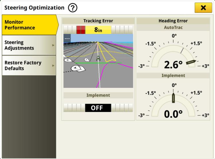
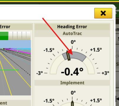
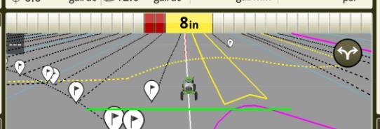
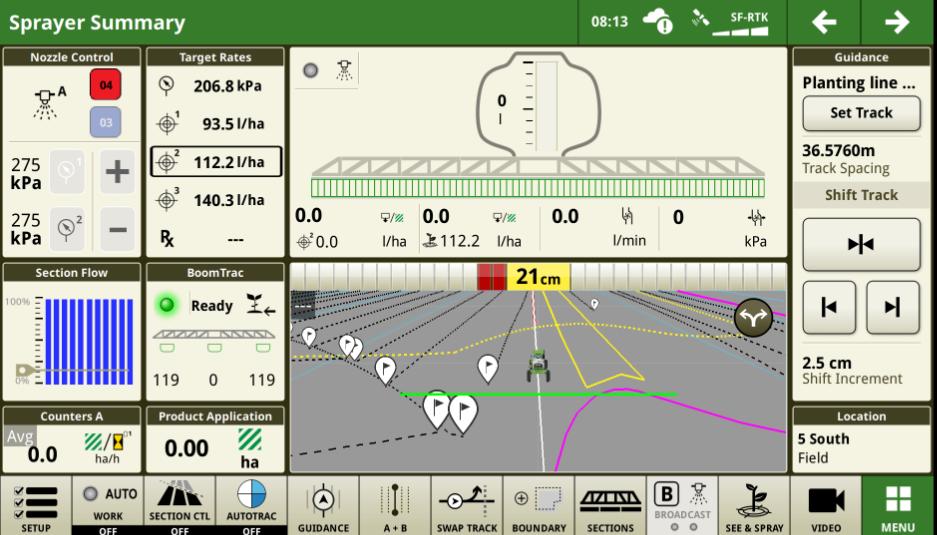
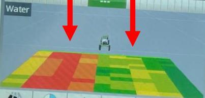
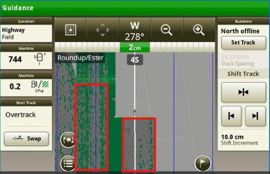
Use the Heading Error Dial in the Steering optimisation page.
This dial shows the deg error between where the machine wants to be heading vs where it is heading. The grey area shows the variance of this range for the last 30sec. Located in Guidance/ Steering/ Monitor Performance
AutoTrac Fine Tuning
Before making any adjustments…
No 'one size fits all' but below is good starting point
Steering setting adjustment golden rules:
• Change only one setting at a time
• Tune settings at the speed you will spray at.
• Tune with the booms unfolded.
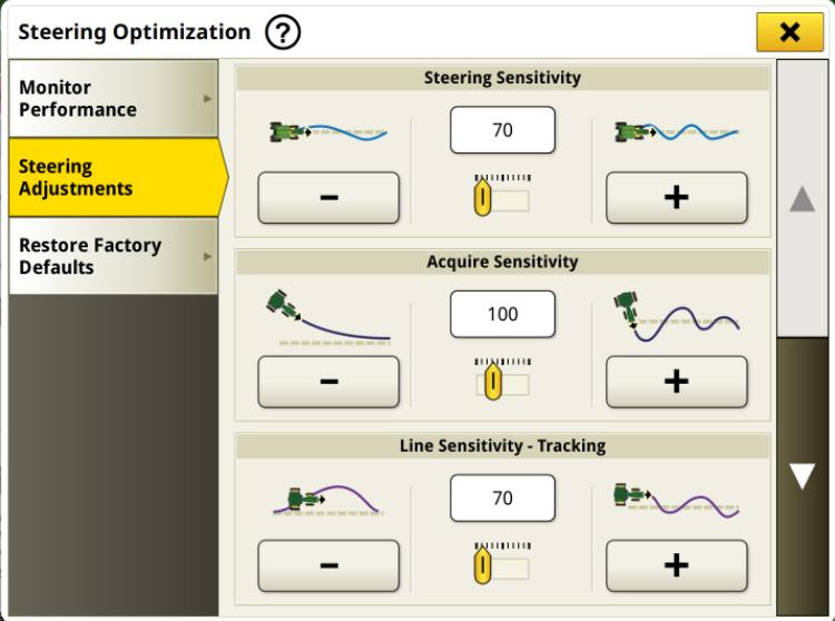
• Start with Steering Sensitivity
• Then Heading Lead
• Then Steer Response Rate.
• Try each individually starting with changes of 20 and work your way in to the best value.
• If slow to acquire increase acquire sensitivity to 120.*
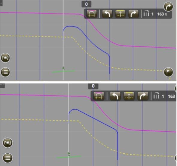
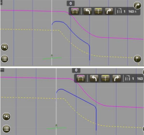
AutoTrac S-ing
Symptom vs Issue
Colour Behavior In-Field Condition Issue
Red Aggressive, Violent Deep, hard wheel ruts. Over Sensitive, Compensating for Hardware issue.
Green Sluggish, Lazy Soft Soil, freshly renovated tracks. Not sensitive enough, Heading Lead Setting too high, Hardware issue.
Blue Off the line Side slope. Receiver, WAS Sensor
Purple Wanders then comes back WAS Sensor
Turn Automation
Setup Guidelines
Good Boundaries = Good Performance
• Boundaries are the foundation of ATTA
• Field boundary = edge of the working area (absolute limit).
• Inaccurate boundaries will result in turns occurring in the wrong spot or ATTA having to resort to other turn types to make the turn.
• Compatible on MY22+ 4xxR/6xxR sprayers
AutoTrac Turn Automation
Requirements
ATTA Usage Requirements:
Gen4 or G5 Integrated
Automation 4.0 activation or G5 Advanced License.
Software version 10.31.3676-103 (25-2) or newer.
Setup file from John Deere Operations Center contains AutoPath data
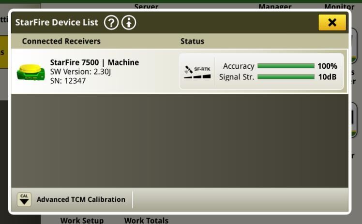
StarFire 3000/6000/7000/7500 Receiver using SF1, SF2, SF3, RTK or SF-RTK.
Following functionalities are NOT available in Sprayer AutoTrac Turn Automation:
• Speed Control
• Sequence Setup
• Speed settings for in-field and turn speed
• AB Curves, Adaptive Curves, and Circles
Following track types are supported with Sprayer AutoTrac Turn Automation:
• Straight track
• AutoPath (rows)
• AutoPath (boundaries)
ATTA – AutoTrac Turn Automation
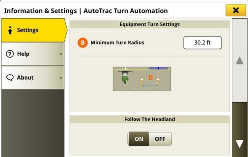
Follow the Headland
• Compatible with Straight Tracks
Screen Run Through
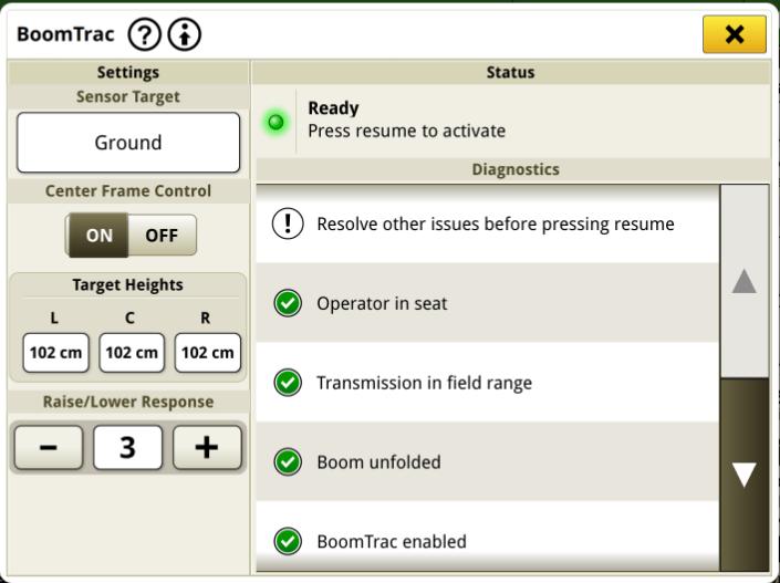
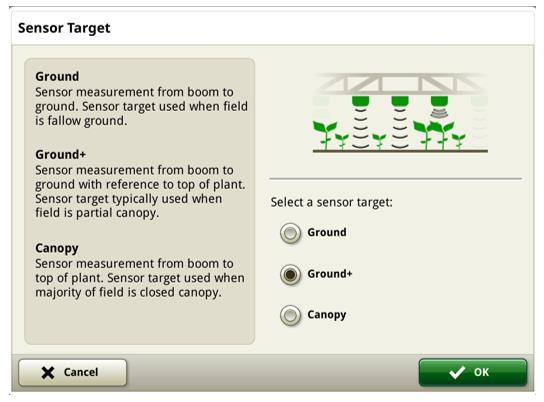
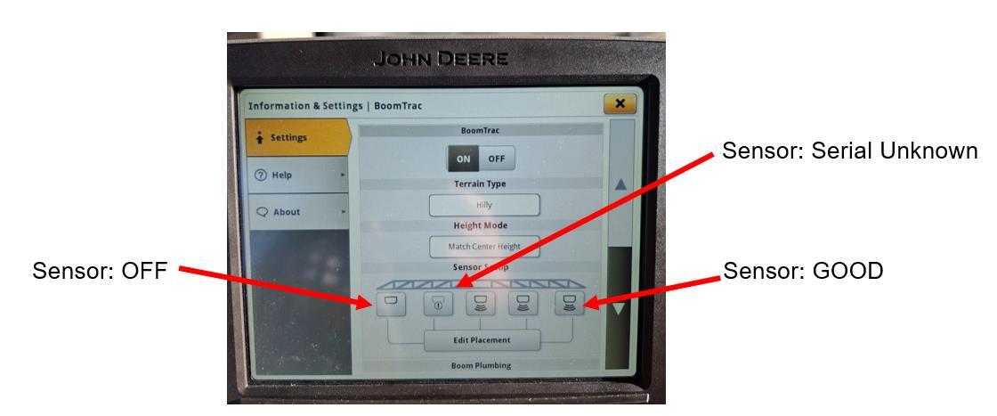
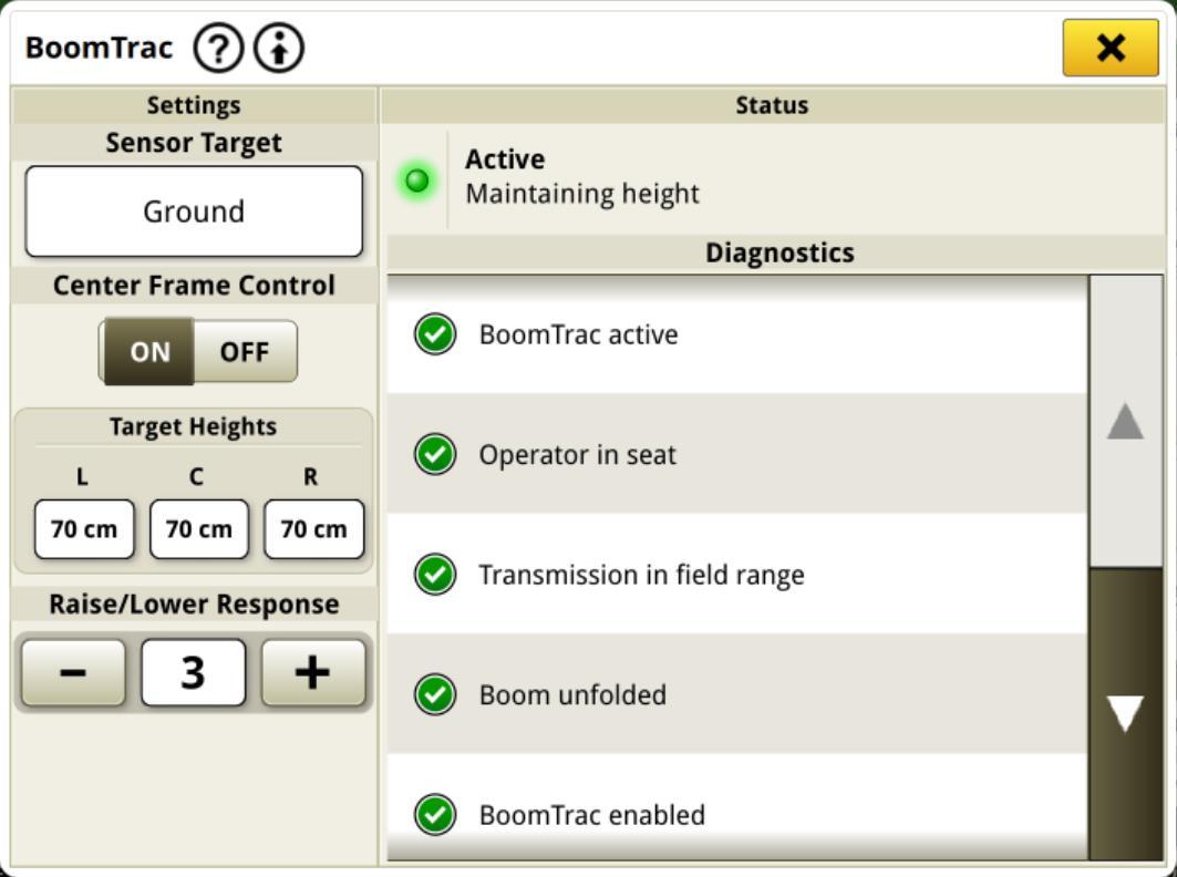
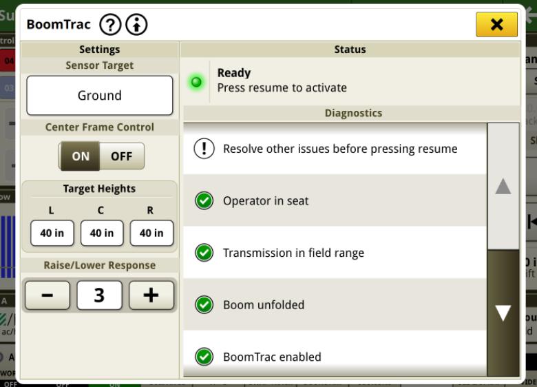
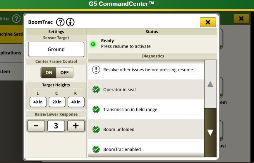
Sensor Target BoomTrac Setup
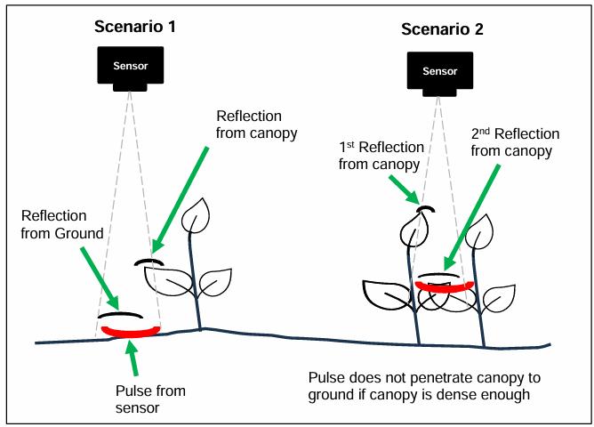
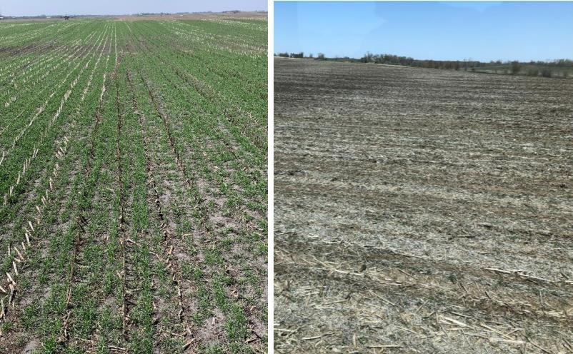
Ground: Use when targeting the height above ground with no canopy.
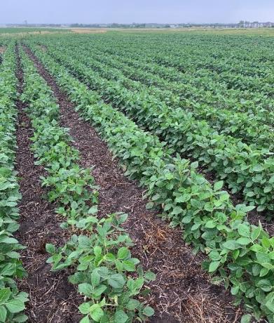
Ground+: Use in partial canopy where sensors may fall between rows. It will target the height above the ground, not the canopy. Software 25.2
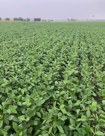
Canopy: Once the height of the plant exceeds the space between the plants, switch to canopy
Screen Run Through
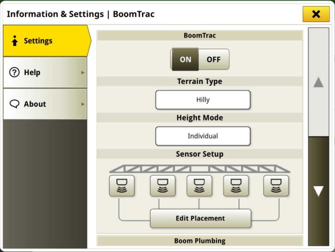
BoomTrac Setup
Center Frame Control
On: Center frame will continue to adjust heights with ground conditions.
Off: Center frame will move to the target height when BoomTrac is engaged and then be disabled. Wings will continue to move.
BoomTrac Setup
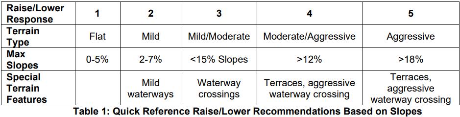
Raise/Lower Response
E-Lift: Full hydraulic actuation
• Emergency lift when the boom goes too close to the ground.
• The lower the boom target height, the more sensitive the boom is to going into E-Lift.
• At low boom heights, response sensitivity may need to be reduced to prevent E-Lift from actuating
Response Sensitivity Table:
Return to Height
• Allows to operator to manually lower the boom and stop at a set point
• Button will need to be pressed again to lower below the setpoint
• Not recommended to use in conjunction with BoomTrac
BoomTrac Setup
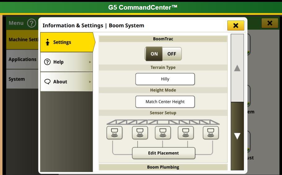
Terrain Type
Hilly: Utilizes the IMU sensor mounted on the boom
• This sensor measures vehicle pitch, roll, pitch rate, roll rate, yaw rate, and acceleration.
• Recommended Terrain Type
Flat: Utilizes the gyroscopic function of the Starfire, mounted on the cab.
• Does not measure the inertia of the boom.
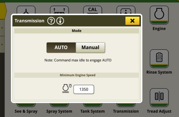
Transmission Setup
Auto = Throttling back automatically.
Manual = fixed Rpm
- For best practices at high speeds (+25kph) leave at Auto and increase minimum rpm (e.g., 1600rpm).
BoomTrac Setup
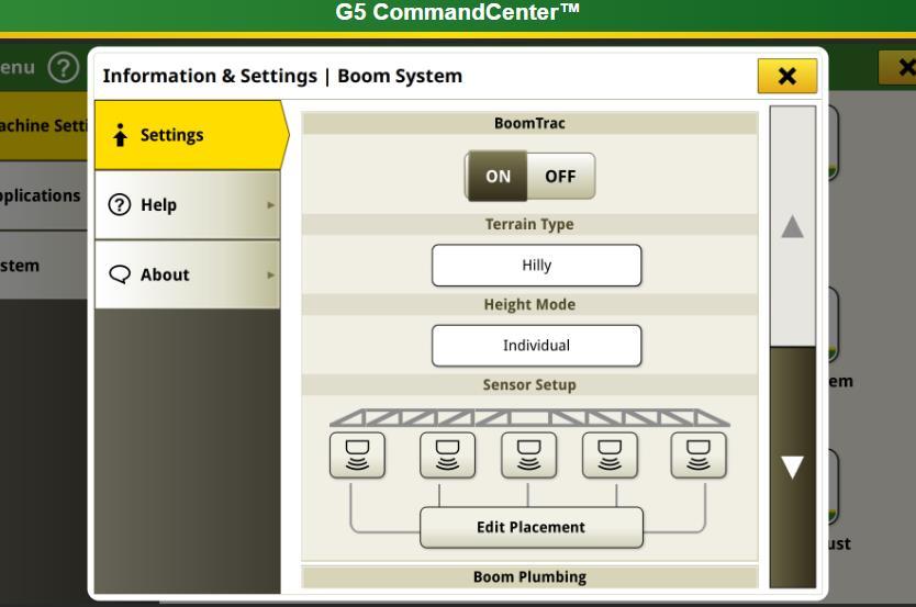
Reactive vs Best stability
Most Reactive
• Canopy
• Individual
• Sensitivity 5
• Transmission Mode Auto
• Min Eng RPM = 1600-1700
Best Performance
• Ground+
• Individual
• Sensitivity 3
• Transmission Mode Auto
• Min Eng RPM = 1500-1600
ExactApply
ExactApply
Deliver effective coverage with precision and manage drift.
• 30-Hz and 15-Hz pulsing
• Auto A/B nozzle switching with pulsing
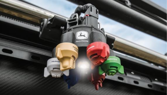
• Individual nozzle control
• Turn compensation
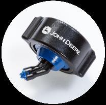
• LED light built into nozzle body
• Consistent pressure and spray pattern
Sprayer Speed Change
Theory of how machines maintain rate while changing forward speed
Conventional Sprayer solution
Changes pressure to maintain rate, Causes changes to Droplet size Has small spraying speed window
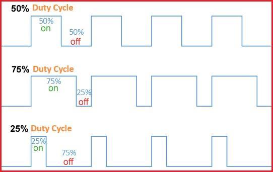
Knowledge check: What is the recommended Duty Cycle?
Exactapply Value
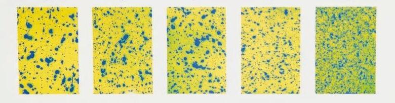
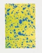
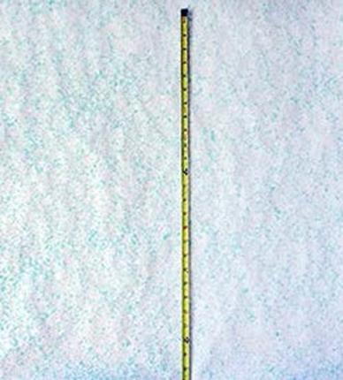
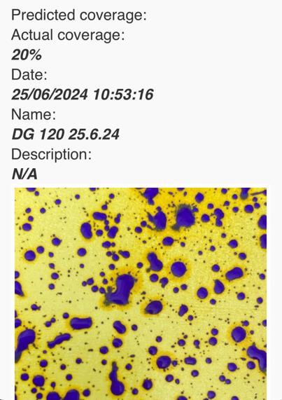
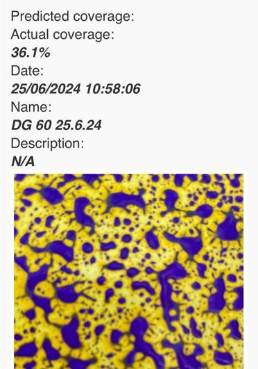
Spray Pattern Testing at 10, 30 Hz
Which is better?
Source: Iowa State University – Department of Ag Engineering- Extension Services Ames, IA
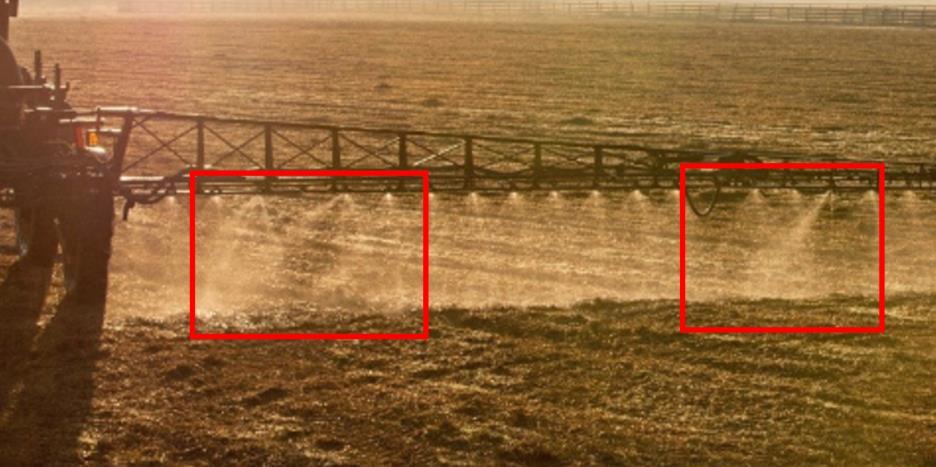
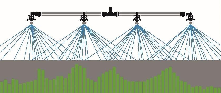
Nozzles are dephased when pulsing to limit skips
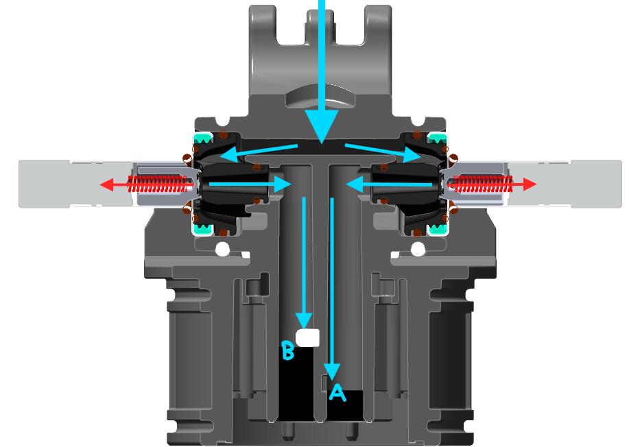
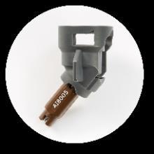
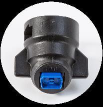
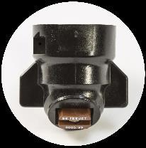
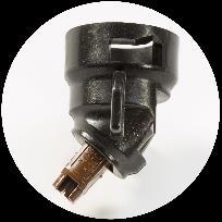
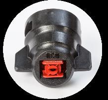
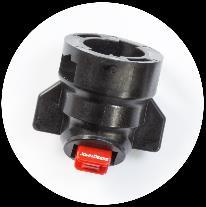
Nozzle Body
ExactApply – Setup
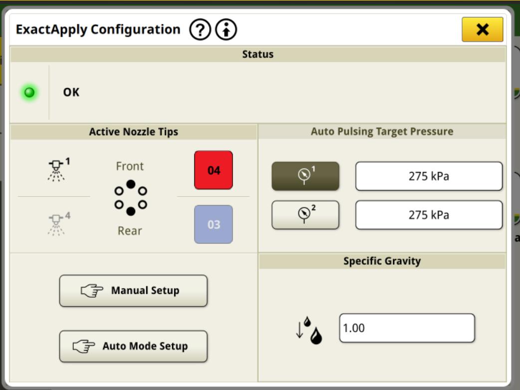
Where do we do this in the Display?
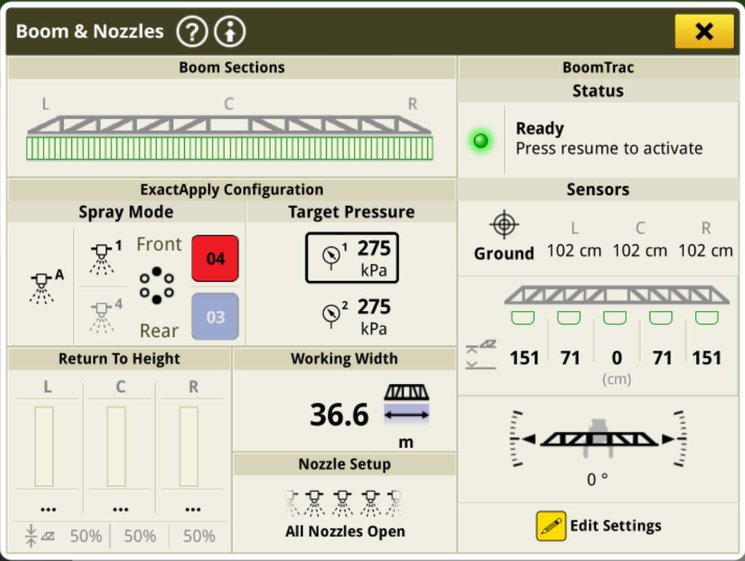
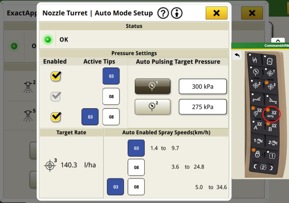
Target Pressure: Set to pressure that will achieve desired droplet size
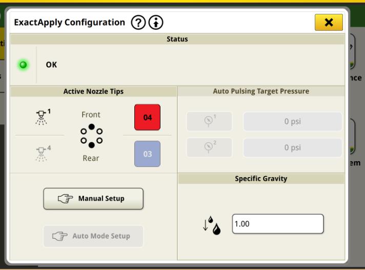
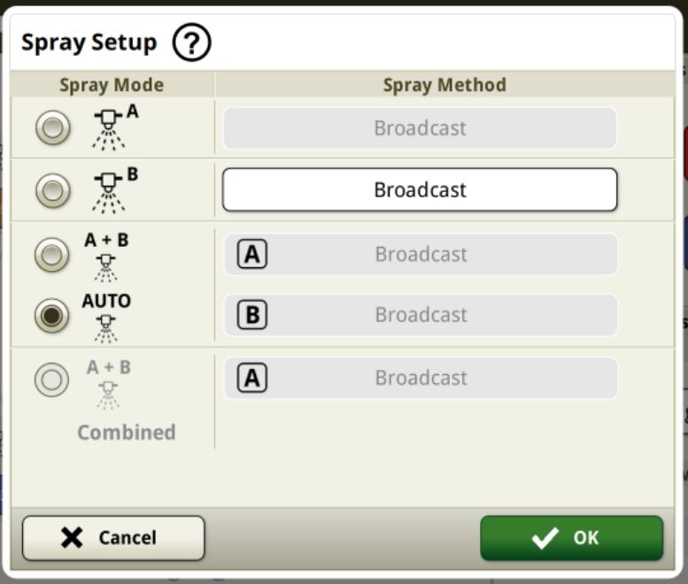
Spray Mode: Adjust active nozzle tips and configuration
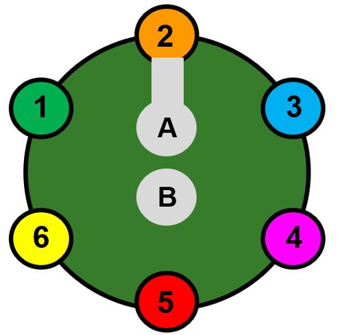
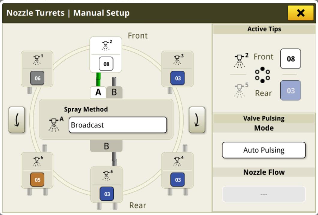
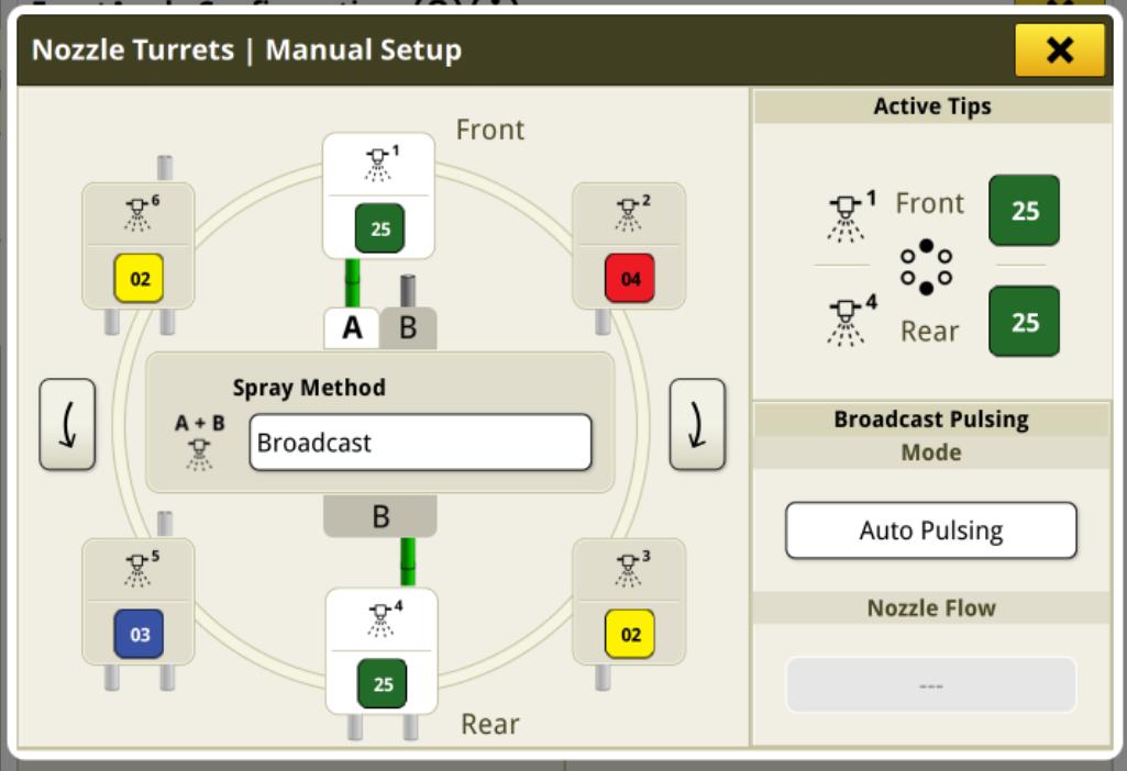
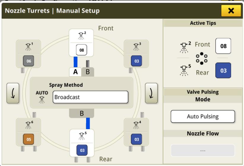
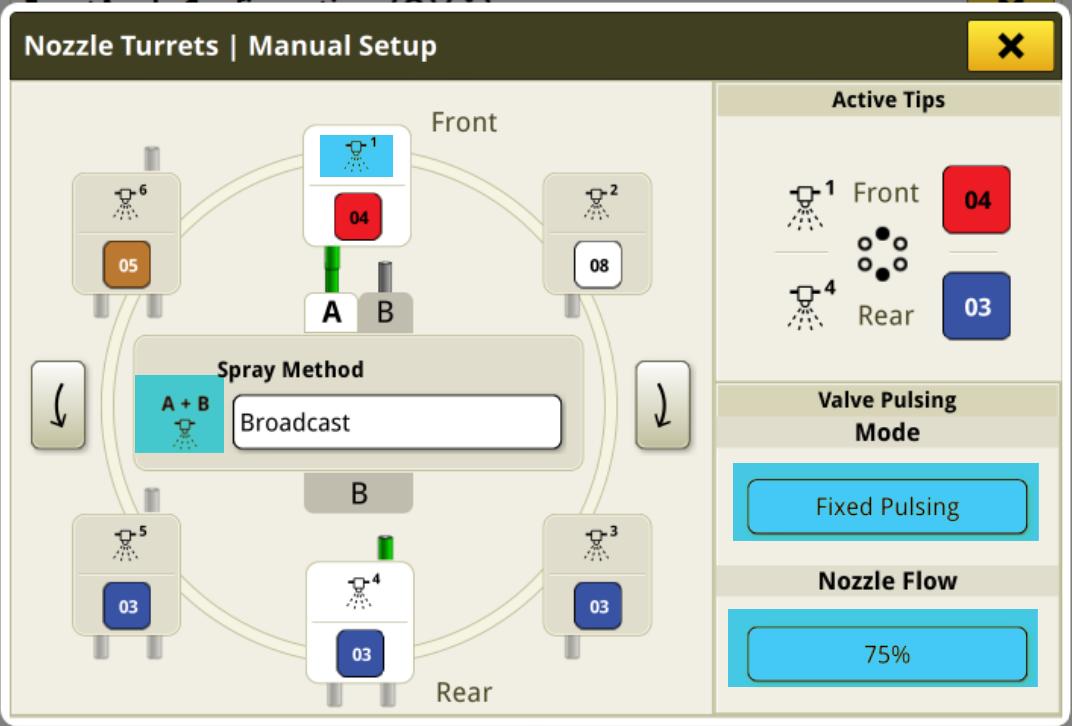
Boom & Nozzles – Manual Setup
Green Hose: Nozzle Active
Grey Hose: Nozzle available, Not active.
Blue Hose: Auto Switching with pulsing active
ExactApply – Setup
Boom & Nozzles – Auto Switching with Pulsing
Creates much larger speed operating range
• Small nozzle at low speeds
• Large nozzle at medium speeds
• Both nozzles at high speed
**Does not switch down until very low duty cycle.
If a large speed range is required, recommend manually selecting the nozzle on the armrest.
ExactApply Auto Switching
ExactApply – How to Prevent Dripping
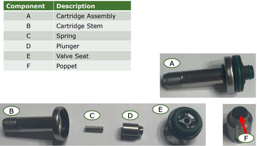
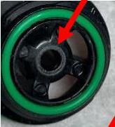
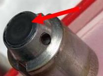
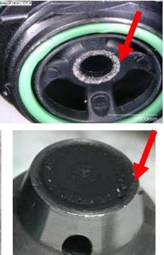
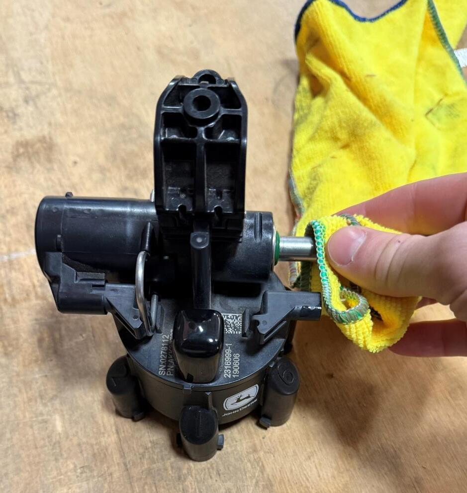
Inspect ExactApply Components
Potential cause for dripping:
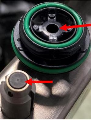
Residue inside of the valve, stopping the plunger (D) from sealing against the valve seat (E).
If this is found, another boom-only rinse needs to be done using clean water.
ExactApply – How to Prevent Dripping
Inspect ExactApply Components
Potential cause for dripping:
• Seal damage
o Not seated correctly or missing
o Flat or damaged O-rings
o Damaged figure 8 seals in turret
o Replace damaged seals.
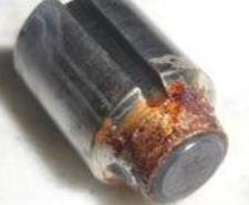
• Broken springs and corroded plunger
• Spring should be 13mm in length. Replace broken springs with KK114043
• KK114043 is a stronger spring that is more resistant to failure.
• If the plunger is corroded and not able to move freely, it needs replacing
• Red Spring (new) has 33% more force than old spring
ExactApply – How to Prevent Dripping
Inspect ExactApply Components
Potential cause for dripping:
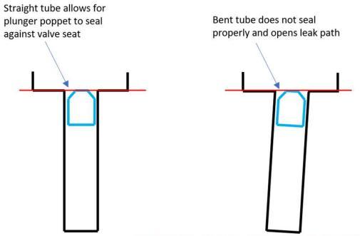
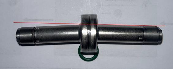
• Bent Valves. Caused by incorrect removal from the nozzle body.
• Bent valves do not seal and need to be replaced.
ExactApply – How to Prevent Dripping
Inspect ExactApply Components
Potential cause for dripping:
• Valve seat and plunger wear.
• Replace worn components.
• Torque valve seats using the supplied torque tool.
• Dry cartridge before reassembling to avoid cartridge seizing inside the coil
Good Fair Replace
Inspect ExactApply Components
Before reinstalling Solenoid Coil, ensure cartridge is dry. If installed with residue on the outside of cartridge, steel cartridge can seize with inside of steel solenoid coil
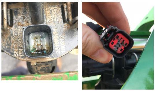
ExactApply – Connector Corrosion
How to prevent corrosion in pigtail harness
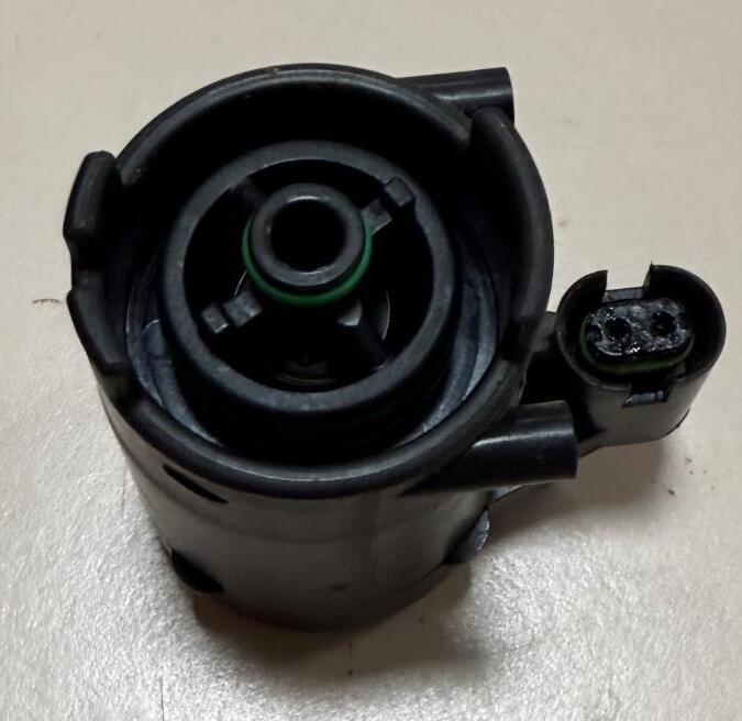
Complaint: Nozzle body/s fail.
Issue: Water/solution ingress into connector and contacts with terminals/pins.
Solution: Apply John Deere’s Di-electric grease to connector terminals.
John Deere Di-electric Grease PN#: T242210
ExactApply – How to Prevent Dripping
1. Always use rainwater
a) Bore water/Hard water significantly reduces wear life
2. Complete a Boom-Only Rinse, daily, at a minimum
3. If use granular products, use more than 1 rinse tank
a) May be beneficial to pull a cartridge apart to check cleanliness.
4. Perform a pressure relief once finished spraying
ExactApply – How to Prevent Dripping
Pressure Relief
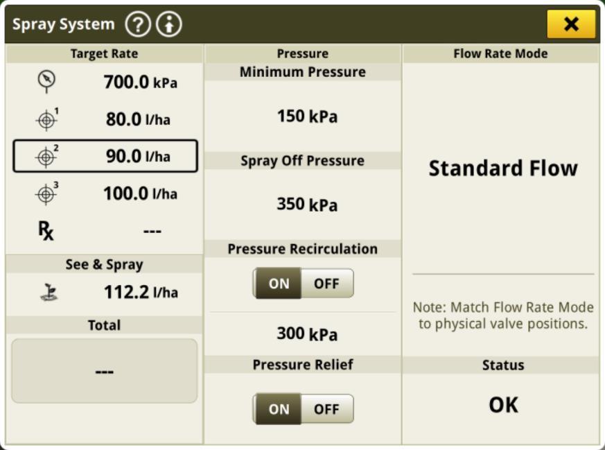
1. Open the Spray System page and toggle on Pressure Relief.
2. With the pump off, press the master on.
ExactApply Nozzle Selection
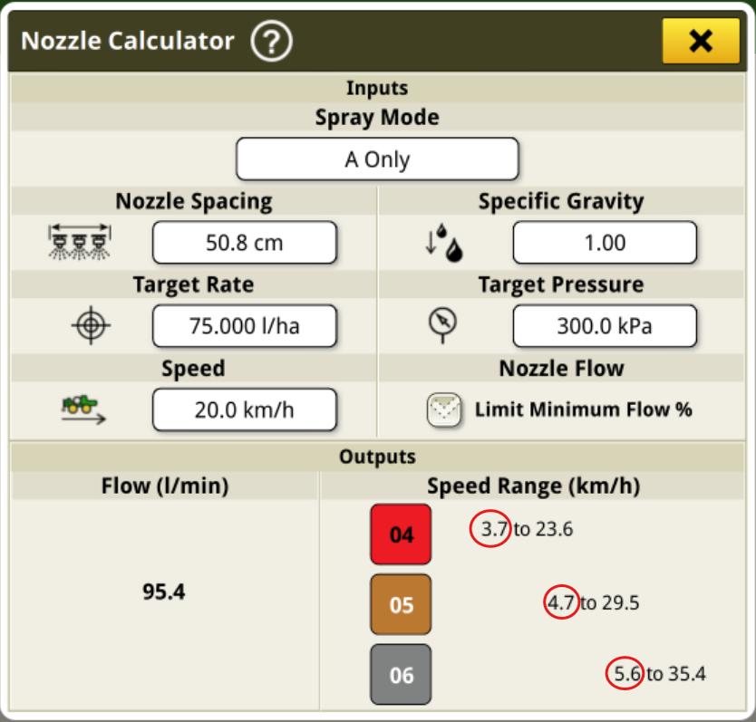
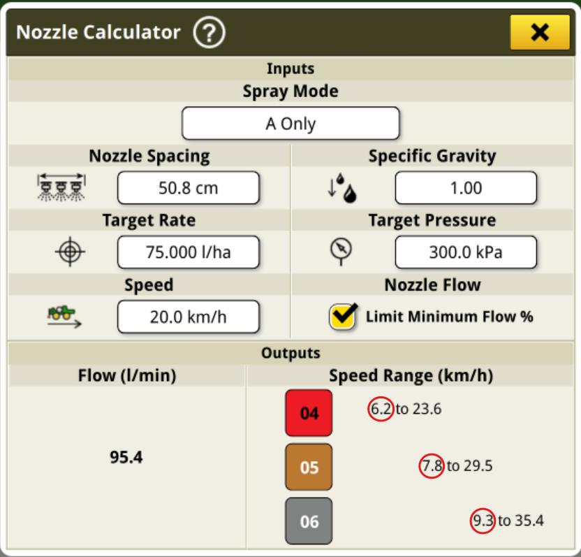
How do you we select a nozzle?
Spraying Inputs:
• Rate
• Droplet Size / Pressure
• Speed
• Nozzle Spacing
• PWM vs Conventional
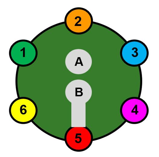
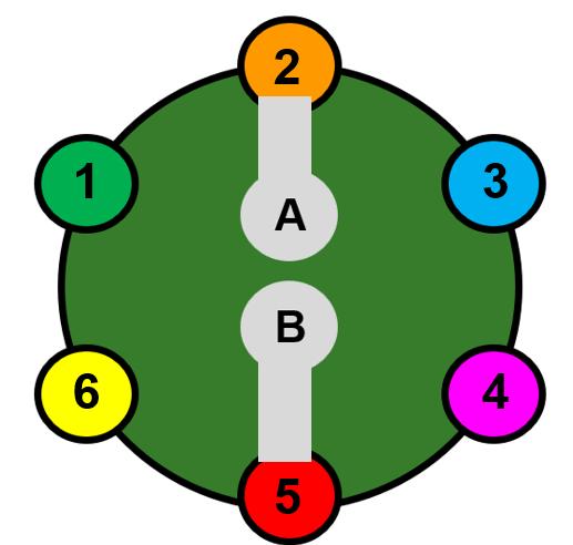
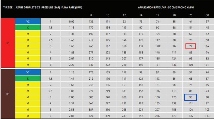
Conventional Red Box
Target Pressure: 3 bar
Target Rate: 75 L/Ha
Target Speed: 25 km/h
Conventional = 04
PWM Blue Box
Target Pressure: Same
Target Speed: Same
Target Rate: Divide by duty cycle
75 / 0.75 = 100L/Ha
PWM = 05
ExactApply Nozzle Selection
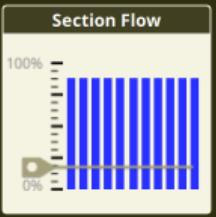
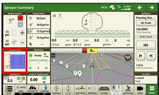
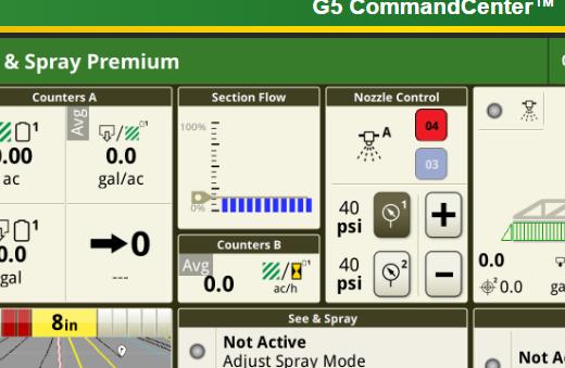
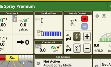
Section Flow
The blue bars on my machine always look like this.
Ideal Duty Cycle = 65-75% at spray speed
Grey Line = Minimum Duty Cycle
What happens when the bars hit the grey line?
- System changes pressure to maintain rate.
- Droplet size needs to be considered.
How do we change Duty Cycle?
- Speed
- Increase Pressure (Reduce DC%)
- Reduce Pressure (Increase DC%)
- Change nozzle (change orifice size).
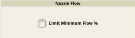
When to use it
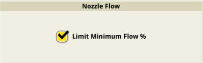
Limit = 15% @15Hz (A Only, B Only)
Limit = 30% @30Hz ( A+B Combined)
Actively calculates based on speed, rate, tip size and spacing in display.
Reset by rotating nozzle body in Nozzle Turret Page
Spray System Setup (Let's go spraying)
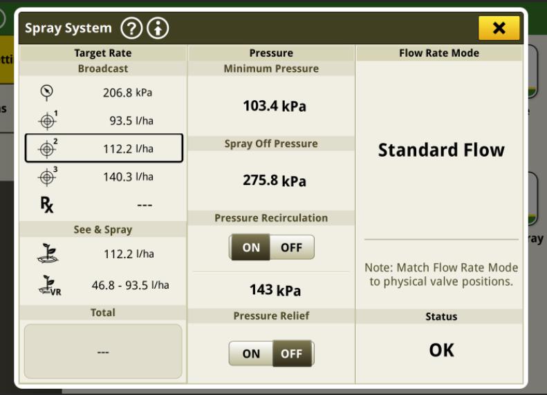
Spray System Screen
Minimum Pressure:
Set to lowest pressure that will maintain a full pattern.
Spray Off Pressure:
Pressure in the boom when nozzles are off. Also controls agitation when not spraying. Set to the same as target pressure
Spray System
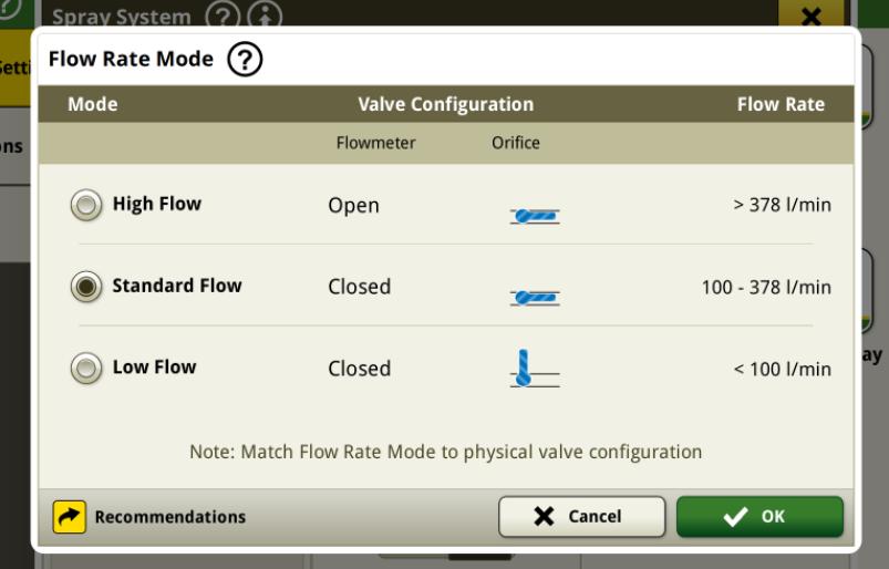
Flow Rate Mode: Depends on the flow required for the rate and speed. Needs to be match the physical orifice valve position.
ExactApply – Setup
Spray System – Advanced Settings
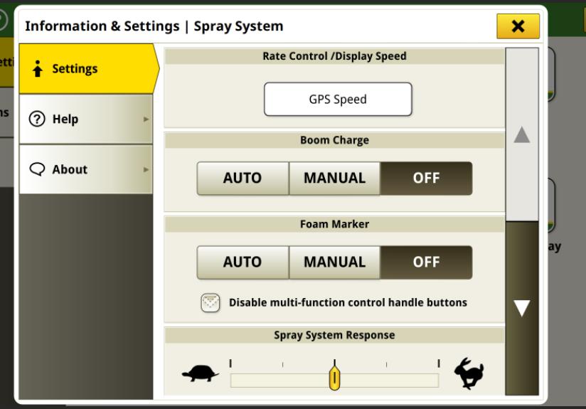
Rate Control: Set to GPS Speed
• If signal is poor use wheel speed.
Boom Charge: Auto – Calculates the boom pressure based on previous run. Reduces overapplying/underapplying when leaving the headland.
Off – Set to off when in point rows
Spray System Response: Increase when system does not reach target in 4 sec coming out of headland.
Decrease if system is erratic.
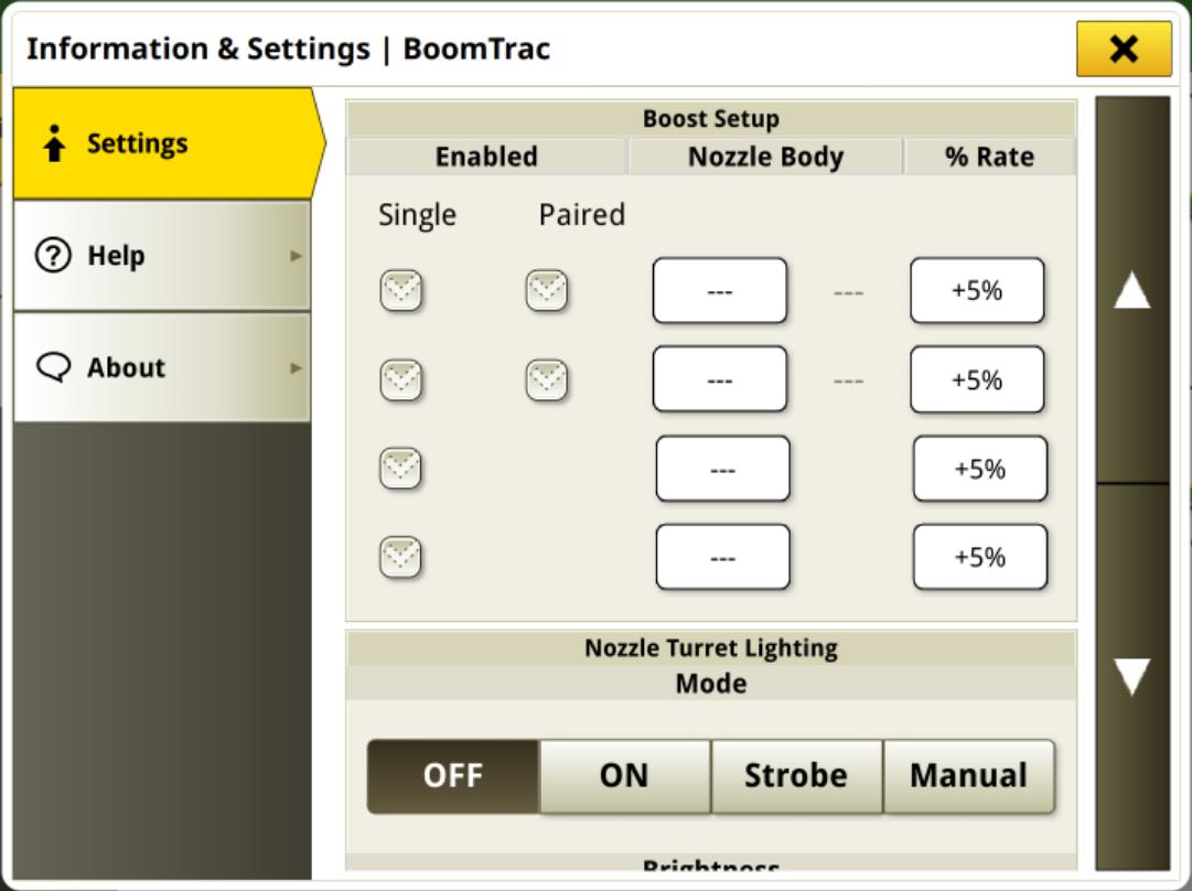
Boom & Nozzles – Advanced Settings Boost
• Any single nozzle or pair of nozzles can be boosted up to 25%
• E.g. Boost nozzles behind wheel tracks
• Does not add additional flow to the boom. Steals from the other nozzles.
• Average rate applied across the boom width is the same
ExactApply – Setup
Multi-Rate
• Currently Available on MY22-26 machines. Machines before MY24 will need harness modifications. 227370
• Can apply different rates up to 11 virtual sections across the boom
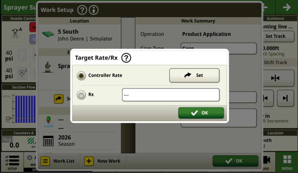
• Requires a prescription (Rx)
• To enable Multi-Rate, Set MNA 122 = 1 and complete a key cycle.
Where to import Rx files
Nozzle Wear
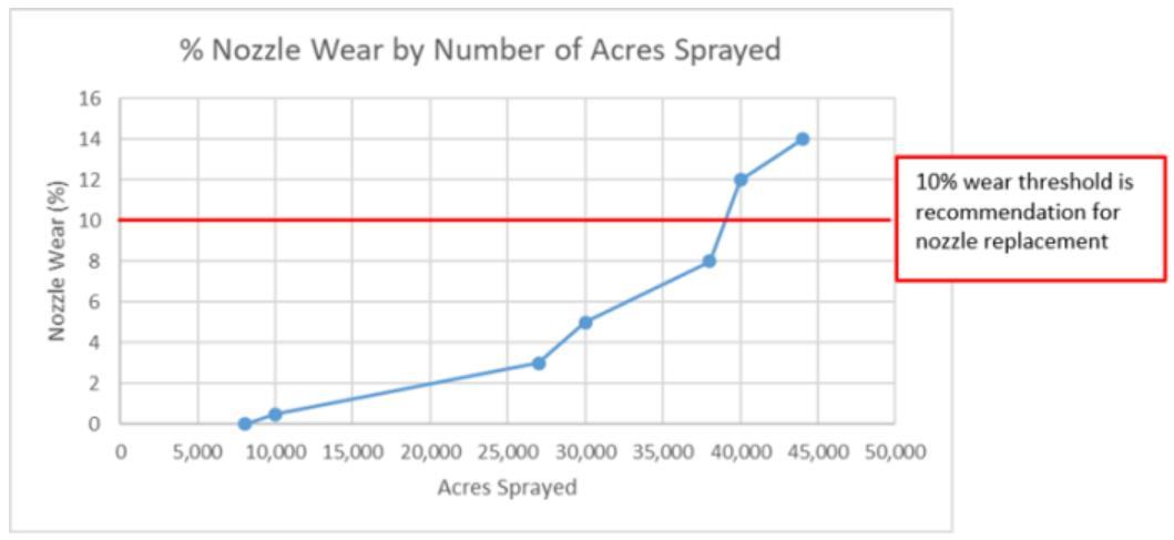
Nozzles are Wear Parts
• Nozzles are wearable components. The orifice size and pattern change over time due to wear.
• Worn nozzles will cause performance and efficiency issues
• Increase the potential of weed resistance
• Reduce crop yield
• Extra passes over the field
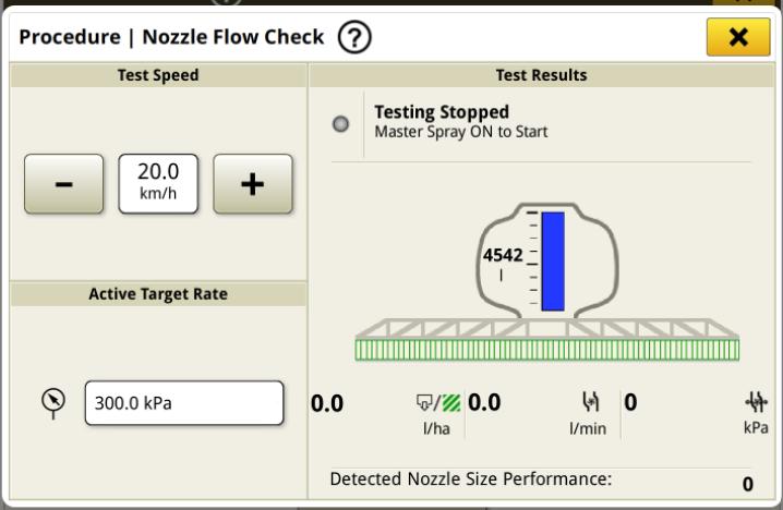
How to know if your nozzle has worn:
• If the flow from a nozzle varies more than 10% above or below the average of all the nozzles for the factory stated flow at 2.8 Bar.
• How to check?
Nozzles are Wear Parts
Checking for Nozzle Wear
Automated Calibration
Replace Nozzles…
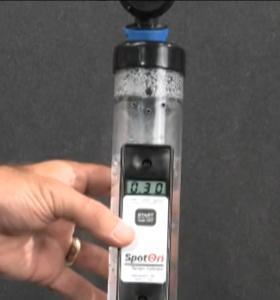
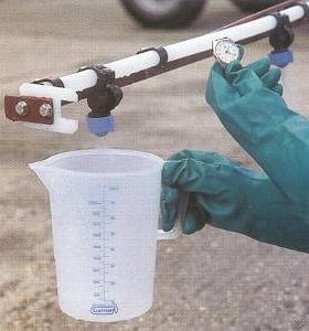
Manual Nozzle Calibration
If the flow from a nozzle varies more than above or below the average of all the nozzles or the factory stated flow at 2.8 Bar (40psi).
Calibrate nozzles on a regular basis
Photo from Turf-Tec International
Solution Rinse & Boom Rinse
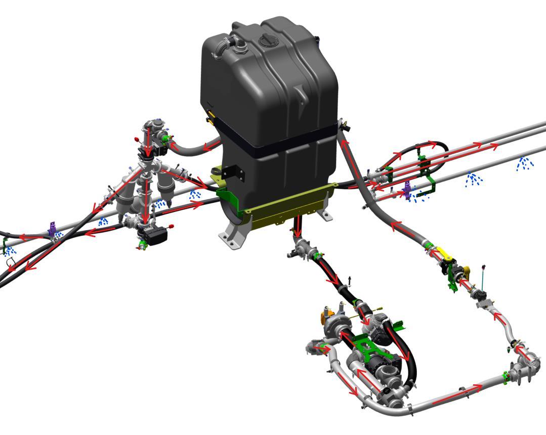
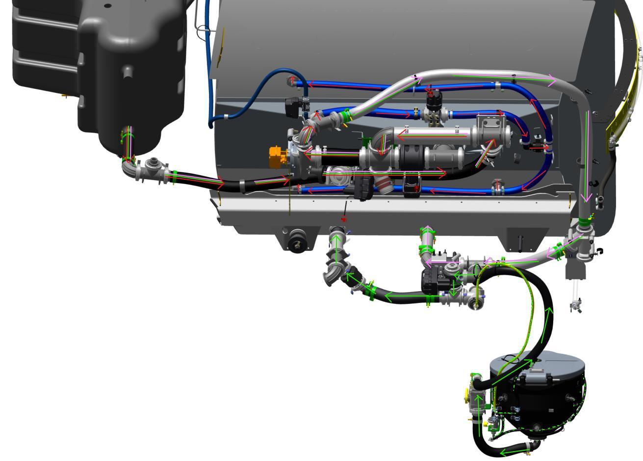
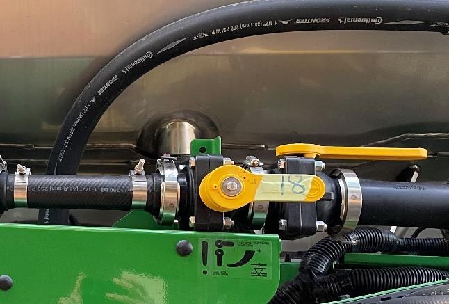
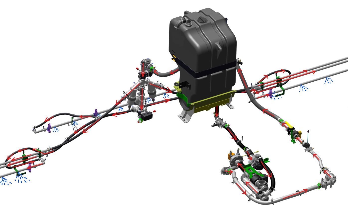
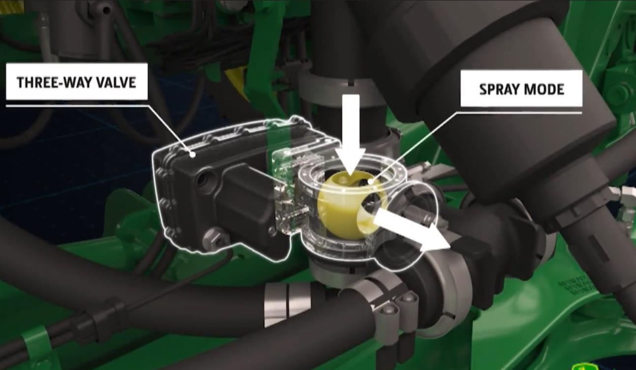
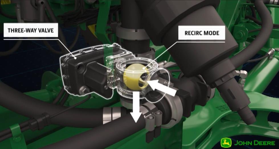
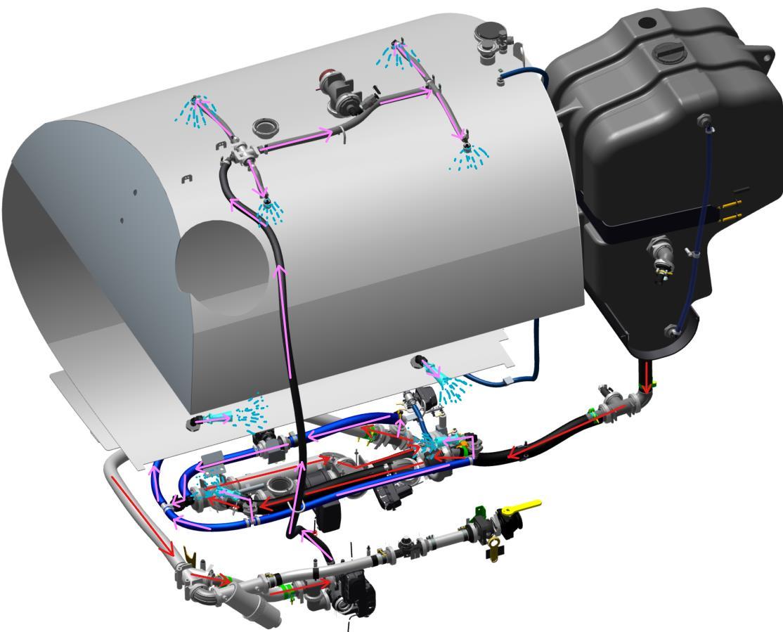
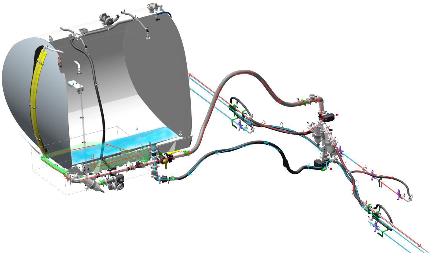
Component location
Solution System & Boom Rinsing
Bypass Valve Air Bleed Solenoid
Solution Pump
Agitation Valve
Flow Meter Shut-Off Valve Boom
Rinse Eductor Valve
Recirc Valve
Orifice Valve
Flow Meter
Rinse Tank Sump Valve
Solution Pump
Preparation for Boom Rinsing
Product Reclaim / Air Purge
What to do before any rinse:
Product Reclaim
• Returns solution from the boom to the solution tank using compressed air.
• Use before boom only rinse when there is solution remaining in the tank.
Air Purge
• Uses pressurised air to push solution from the boom out of the nozzle body
• Use before rinse cycle when the solution tank is empty.
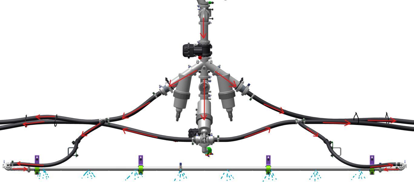
• Recirculation lines are pressurized from both sides of each section when in spray mode/boom rinse
*Return line to Solution Tank is not rinsed (boom only)
Solution System & Boom Rinsing
Boom Only – Rinse Water (Clean Water)
Recap
• Product Reclaim / Air Purge
• Configure Sprayer
• ExactApply Setup
• Boom-Only Rinse
• Clean Filters
• Reset Spray Settings
Solution System tank only Rinsing
Tank Only – Rinse water (clean water)
• Rinses spray solution from solution pump and tank with water from rinse tank.
• Use when spraying out the rinsate is not possible and tank residue requires immediate dilution to avoid crystallization
Solution System & Boom Rinsing Solution System
• Removes spray solution from the solution system, tank, and boom plumbing.
• Used when changing crop type, chemical types and before the machine is stored.
• Recommended to complete an Air Purge first
Steps:
1. Eductor
2. Agitation
3. Bypass with Tank Rinse Nozzles
4. Boom Plumbing
5. Tank Rinse Nozzles again – Drain solution
6. Boom Only Rinse (Recommended)
Solution System & Boom Rinsing
Solution System
Solution System & Boom Rinsing Solution System
Solution System & Boom Rinsing Solution System
Solution System & Boom Rinsing
Solution System & Boom Rinsing Solution System
Solution System & Boom Rinsing
Solution System & Boom Rinsing
Solution System & Boom Rinsing
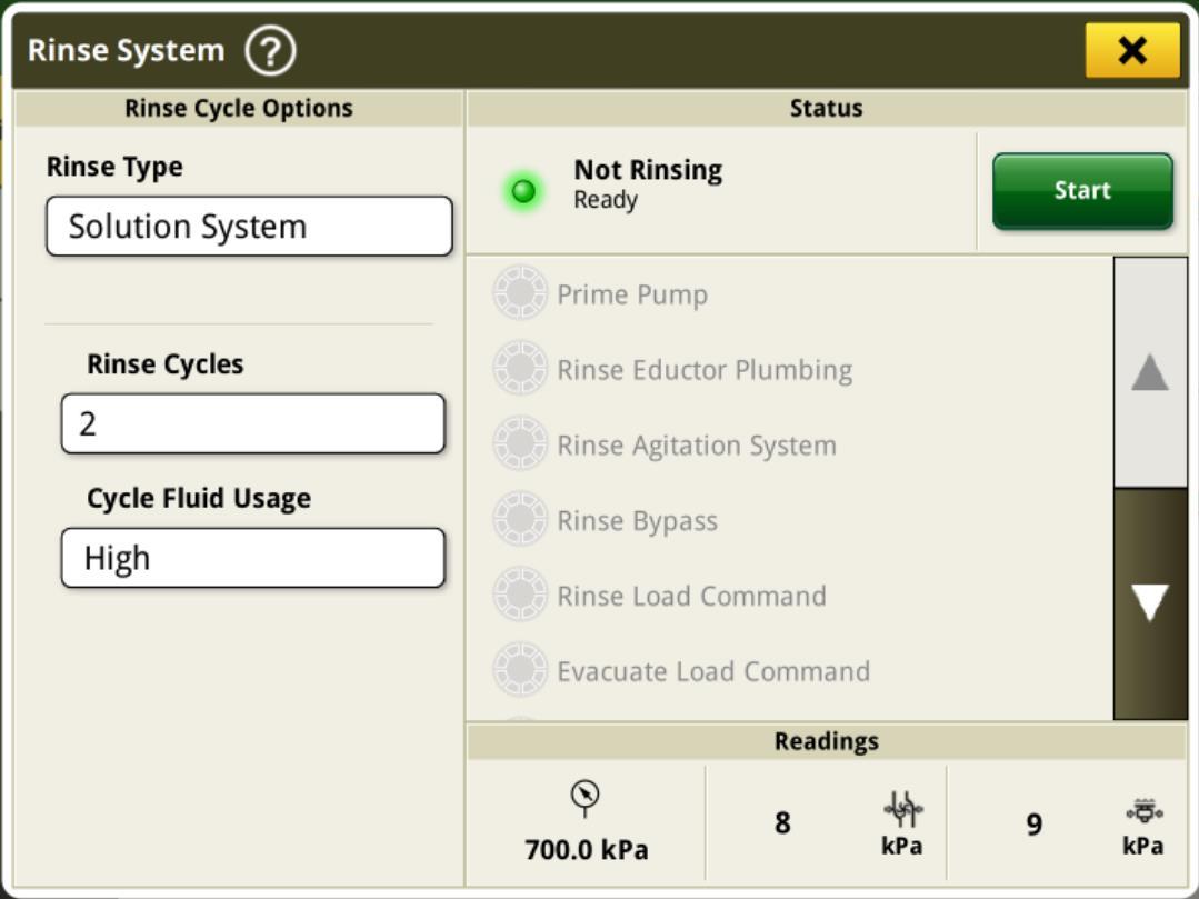
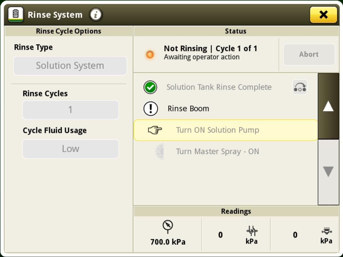
Solution System – Display Setup
*Rinse tank for a 616R is 606L
Solution System & Boom Rinsing Solution System
• Return to cab to spray out Rinsate
• Spray out the rinsate using the same setup as the ‘Daily Rinse’
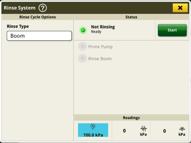
• 700kpa, Fixed Pulsing, 75%, A+B
• After this you may rinse the boom using a Boom Only Rinse once the rinse tank has been refilled if needed.
Solution System & Boom Rinsing Summary
Boom Only
• Rinses Boom Plumbing, pump, flowmeter and recirc lines
• Open Orifice
• Open High Flow valve
• 700kPa
• Spray Mode: A+B
• Fixed Pulsing @50%/75%
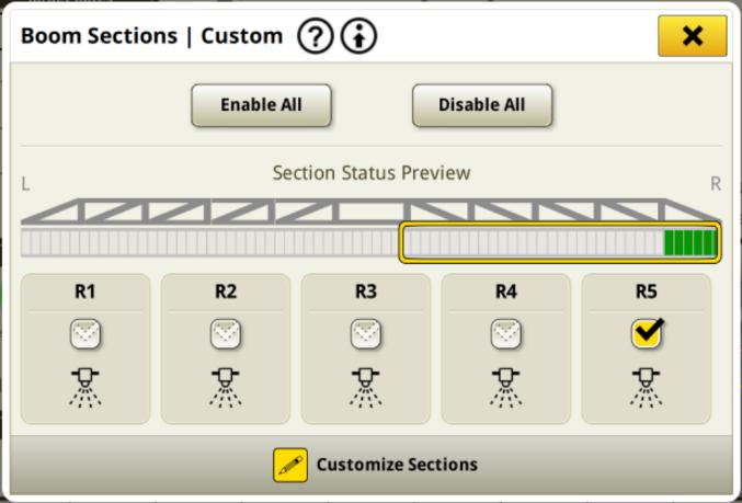
• 10sec / section
• Daily Rinse
Tank Only Solution System
• Uses agitation and tank rinse nozzles to rinse tank.
• Use when you cannot spray out rinsate.
• Used when tank requires extra rinsing.
• Open Orifice
• Open High Flow valve
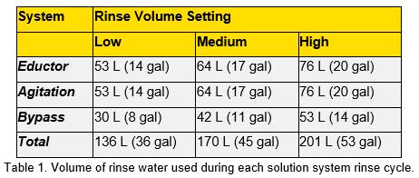
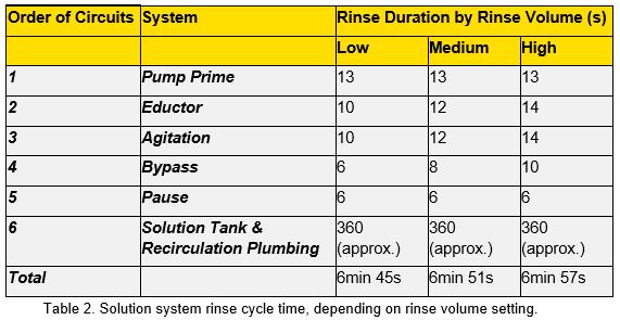
• Select number of cycles and volume
• Rinses eductor, agitation, bypass, boom plumbing and tank.
• Recommended to follow Boom Only Rinse after (refill rinse tank as needed).
* Recommended to do a Product Reclaim and Air Purge before any rinse
See & Spray Select
System Capabilities
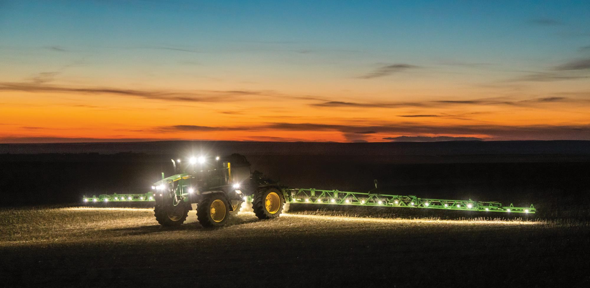
• Green on Brown Cameras (looking for green colour- ONLY)
• Fallow Ground, Stubble, Pre and Post Season Burn-off
• Variable Rate Application
• Day and Night operation
• Operational height is between 50cm-120cm
• Max Speeds:
• 25 km max (inclined nozzles)
• 19 km max speed (downward nozzles)
See&Spray Screen Run Through
See & Spray Prerequisites
• BoomTrac is required to be “ready” for S&S to function, it is not required to be “active.”
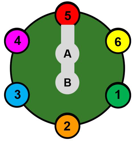
• ExactApply setup with 4,5 or 6 in the rearward position. Nozzle B selected.
• Nozzle is correctly sized for the target speed, rate and pressure.
• Orifice valve needs to be open.
• Sensitivity has been calibrated to the target weeds
• ‘No Crop’ selected as the crop type.
• StarFire Signal, SF3 or higher
• Cameras are clean
See & Spray
Nozzle Selection
Key item to remember before sizing a nozzle
• See & Spray is a rate controlled, pressure-based system
• As speed increases, pressure will need to increase to maintain rate
• Does not have PWM functionality
• Does not have turn compensation*
• Same as a conventional sprayer without ExactApply
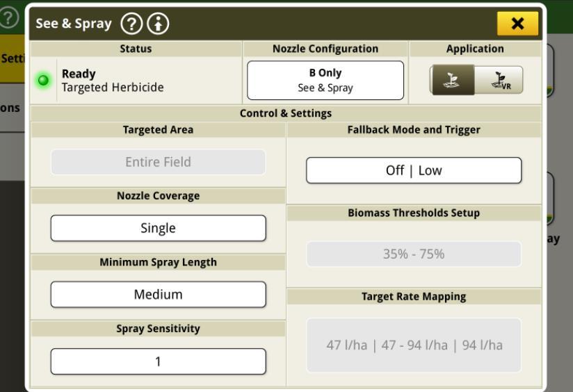
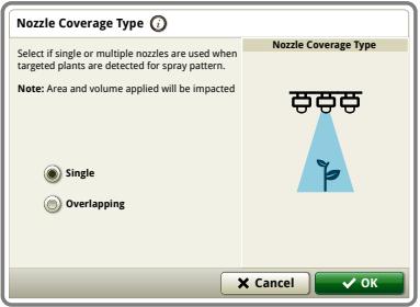
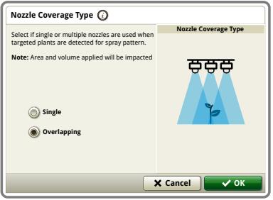
Nozzle Coverage Type
Single Nozzle Coverage: minimum of 1 nozzle enabled, can be up to 2 (if weed goes in between)
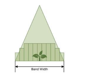
Overlapping Nozzle Coverage: minimum of 3 nozzles enabled, can be up to 4.
See & Spray Select Nozzles
Nozzles for Single Spot vs Overlapping Mode
Single Nozzle Selection:
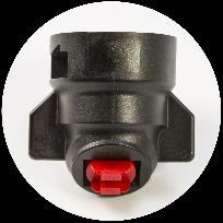
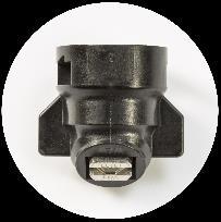
• Nozzle Pattern Type: Even flat fan spray nozzles
– Tapered nozzles will result in inconsistent coverage
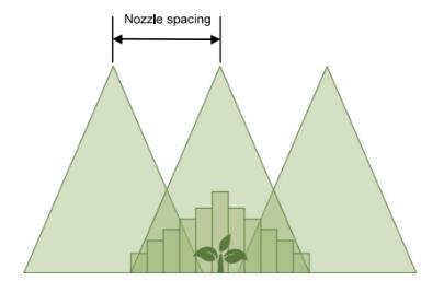
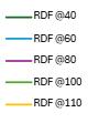
• Spray Pattern Angle: 60/65 degree are ideal for targeted spray
• Boom height needs to be taken into consideration
Overlapping Nozzle Selection:
• Nozzle Pattern Type: Tapered Flat Fan provide consistent coverage
– Even spray nozzles will result in inconsistent coverage
• Spray Pattern Angle: 110 degree are ideal
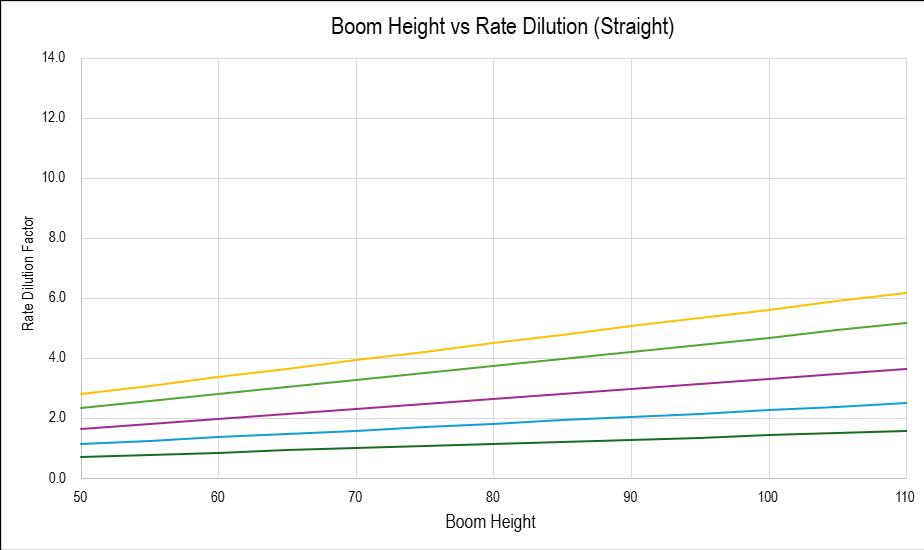
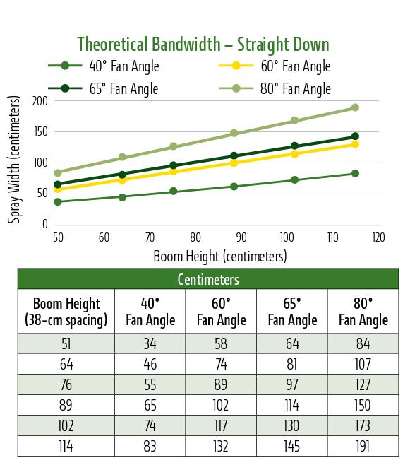
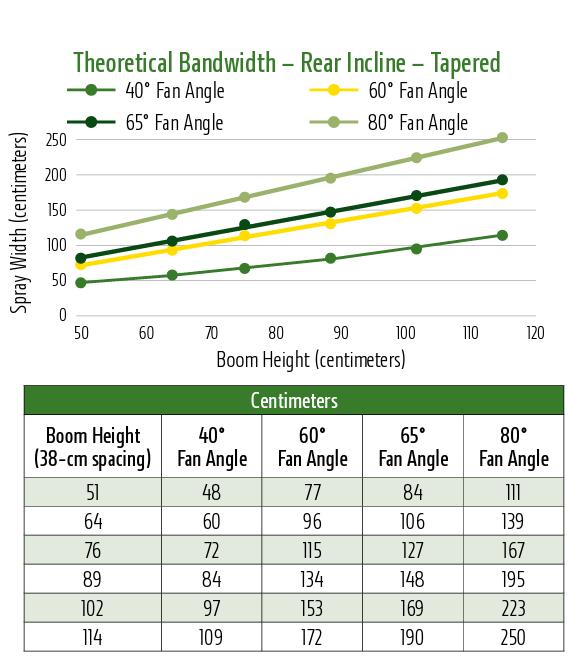
120cm Boom Height
Boom Height Dilution – Straight vs Rear
See & Spray Nozzle Selection
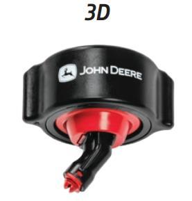
See & Spray Select 25km/h Using Inclined Nozzles
• Using approved inclined nozzles, See & Spray speed can be increased from 19km/h to 25km/h.
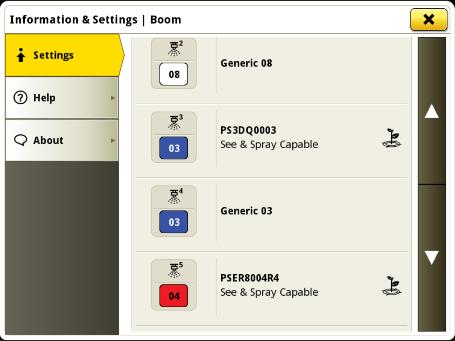
• When using straight nozzles, ‘Generic’ must be selected.
• Only the inclined nozzles pre-populated in the display can be used with See & Spray, so the system can determine the amount of delay that is required
• When swapping between a straight nozzle and an inclined nozzle, you must do a key cycle.
STRAIGHT = “Generic 08”
INCLINE = “See & Spray Capable”
Application
NOZZLE RECOMMENDATIONS
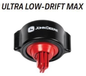
SEE & SPRAY SELECT APPROVED NOZZLES FOR UP TO 25 KPH
CHEMICAL SAVINGS PRIORITIZED
Boom height of >30” to reduce streaking
Contact and systemic herbicides
Systemic herbicides Dicamba approved for some products, follow label Contact and systemic herbicides
Systemic herbicides
approved for some products, follow label Contact herbicides
Systemic herbicides
Dicamba and 2,4-D approved for some products, follow label directions
See & Spray Nozzle Takeaways
• Nozzle size selection is the same theory as a conventional sprayer
• Boom height needs to be considered, and target rate adjusted accordingly
• Single nozzle mode must use even fan nozzles
• Overlapping nozzle mode must be used for tapered fan nozzles.
• Inclined nozzles allow the machine speed to increase from 19km/h to 25km/h
• Correct nozzle selection in the display is critical
• Only the inclined nozzles listed in the display can be utilized
= “Generic”
= “See & Spray Capable”
See & Spray Camera Optimisation
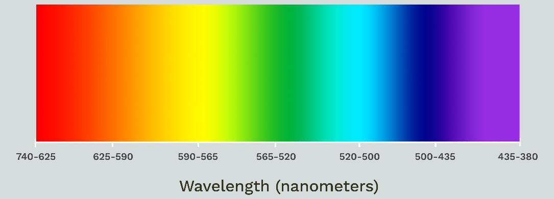
How does it detect weeds?
• RGB Camera
• Detects the colour green within a certain spectrum
• Does not recognize shapes or scan for chrolophyl
• Camera is divided into pixels
• Sensitivity adjusts the number of pixels that need to be joined together to trigger the nozzle
• Sensitivity does not change the spectrum
• Filters assist with weed detection
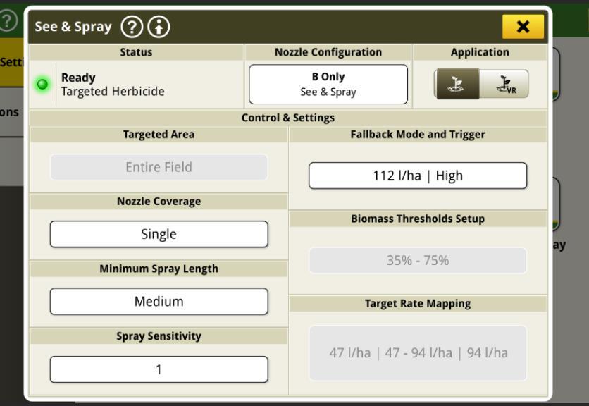
Screen Flows: Spray Sensitivity
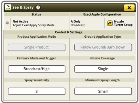
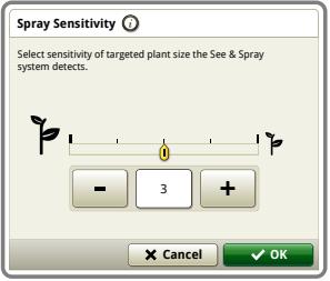
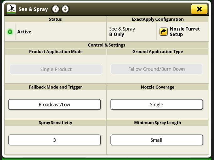
Spray sensitivity has settings of 1-5.
The higher the spray sensitivity setting, your target size will decrease (smaller targets detected)
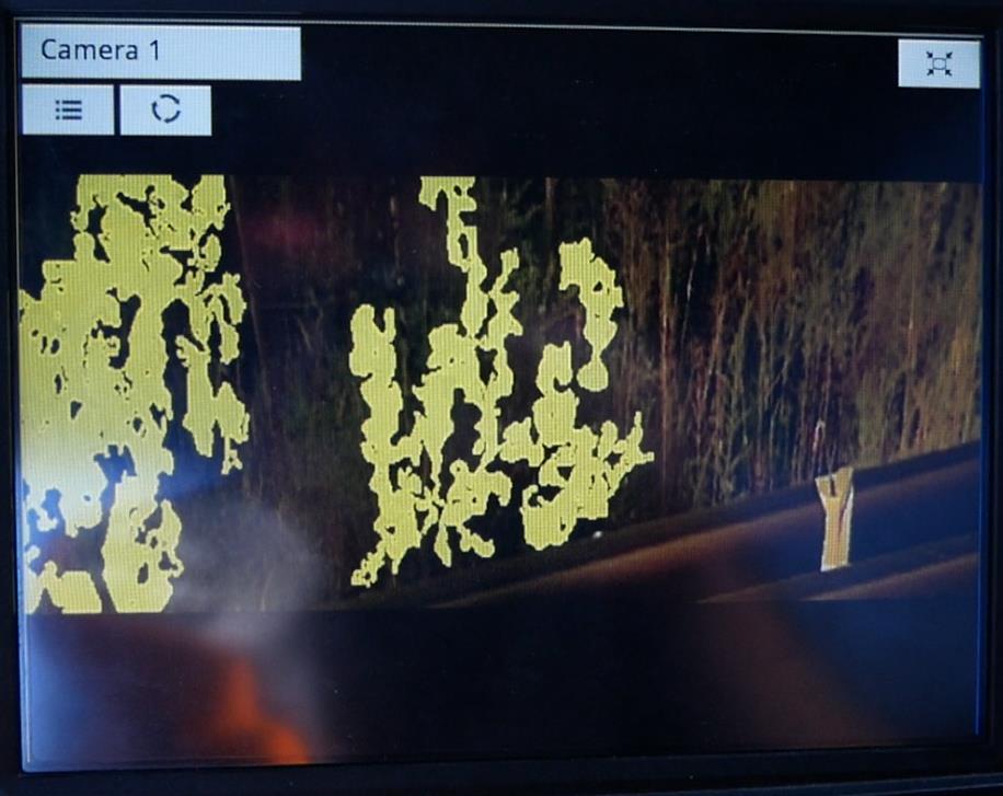
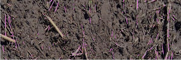
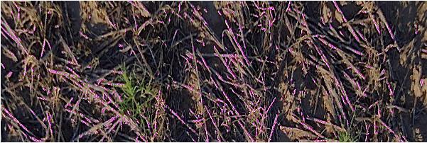
Spray Sensitivity
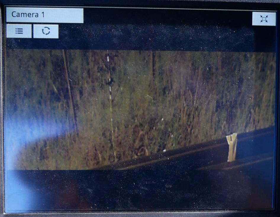
Video feed of camera detecting targets.
Not Detecting Green Pixels
Detecting Green Pixels
Lighting Configuration
Three light configurations
1. On
2. Off
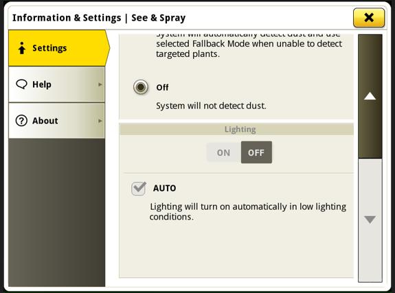
3. Auto
Recommend to use AUTO mode:
• Uses the two light sensors to automatically switch the lights on/off, depending on the ambient lighting.
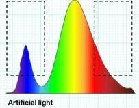
See & Spray - Lights Day-Mode Night-Mode
• Lights OFF
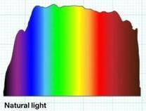
• S&S looks at full spectrum
• Lights ON
• S&S focuses on certain bands.
*It is not recommended to use lights during the day to reduce false triggering, as some weeds may be missed.
Fallback Mode & Trigger Level
Fallback Mode: When machine exits operating parameters; boom height, tip speed, dirty lens, DTC’s (Diagnostic Trouble Codes).
• Off: Affected nozzles will not spray when outside of operating parameters.
• Broadcast: Affected nozzles will broadcast when outside of operating parameters.
Trigger Level
Low: Operating parameters fall well below the threshold. E.g. boom height drops below 40cm.
High: Operating parameters fall just below the threshold. E.g. boom height drops below 50cm.
Low Light operation (Lights On)
This chart goes through optimal day time and nighttime running
Boom Height
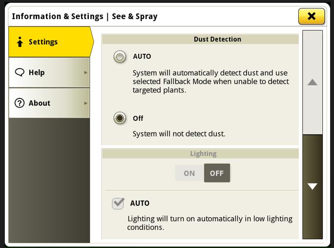
Dust Detection
If the cameras are covered with dust/mud they are not able to detect weeds.
• Dust Detection allows the cameras to go to fallback if dust is detected.
• Only the nozzles associated to that camera will go into fallback (2 nozzles per camera on 50cm nozzle spacing)
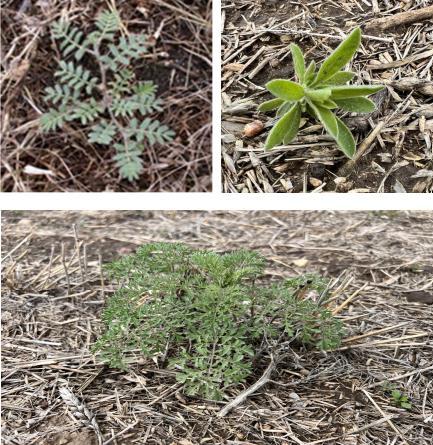
Calthrop Filter
Light Green Weed Filter
• Nozzles are triggered within a certain colour threshold.
• Some weeds are borderline or fall outside of this threshold.
• Stressed weeds commonly change to a lighter colour
• DA 164 can be changed to a 1 on VSM 1-5.
• Coming to Advanced Settings soon.
• Only enable this filter when necessary, as it can lead to false triggering (due to expanding the colour threshold).
Sun Filter
Into the Sun/Out of the Sun Scenario
• When there is a contrast of coverage in the display in one direction vs the other.
• DA 149 can be changed to a 1 on VSM 1-5 to prevent these false triggers from occurring.
See & Spray Select – Cleaning
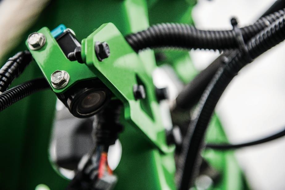
Cameras/Boom Lights
• Clean lenses daily or as required using a spray bottle, damp cloth with water, or low-pressure air.
• Mind detergent can be used if needed
• Inspect cameras for damage and bent brackets, as this will affect performance.
VSM’s
• Ensure that all VSM’s are clean to prevent overheating
• Ensure connectors and caps properly secure before cleaning
• Do not pressure clean around connectors
Water inside lens
Operations Center
DIGITAL TOOLS
APPLYING
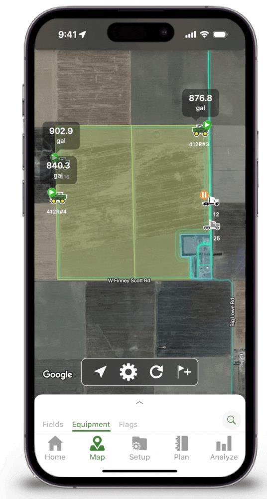
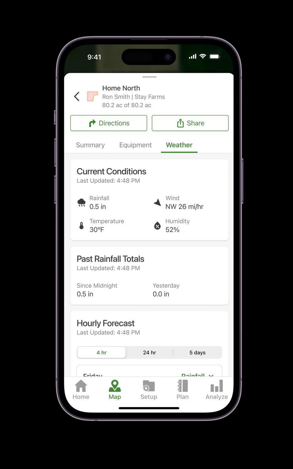
• Operator: Can I make another pass up and down the field before running out?
• Truck: Which product do I need to be bringing to the field?
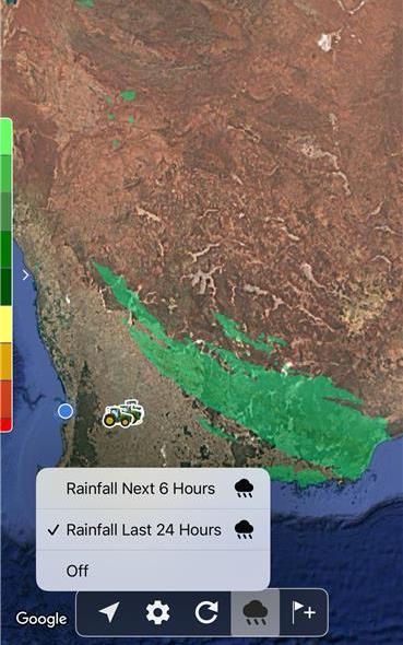
• Farm Manager: How long will the wind and rain hold off?
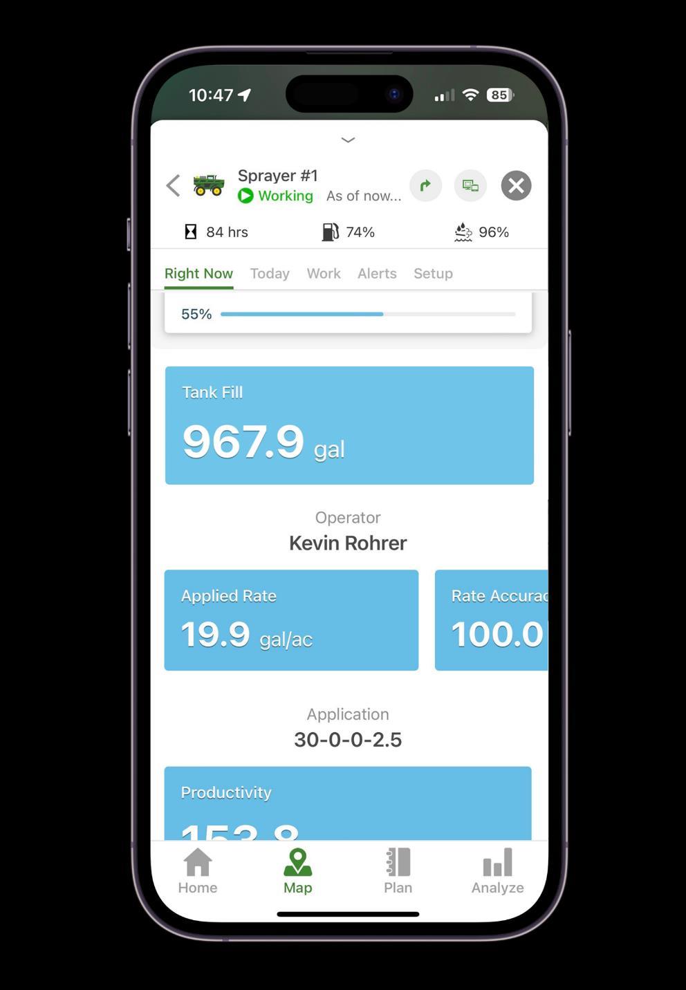
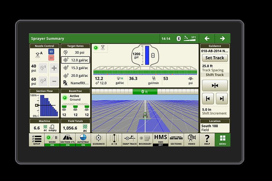
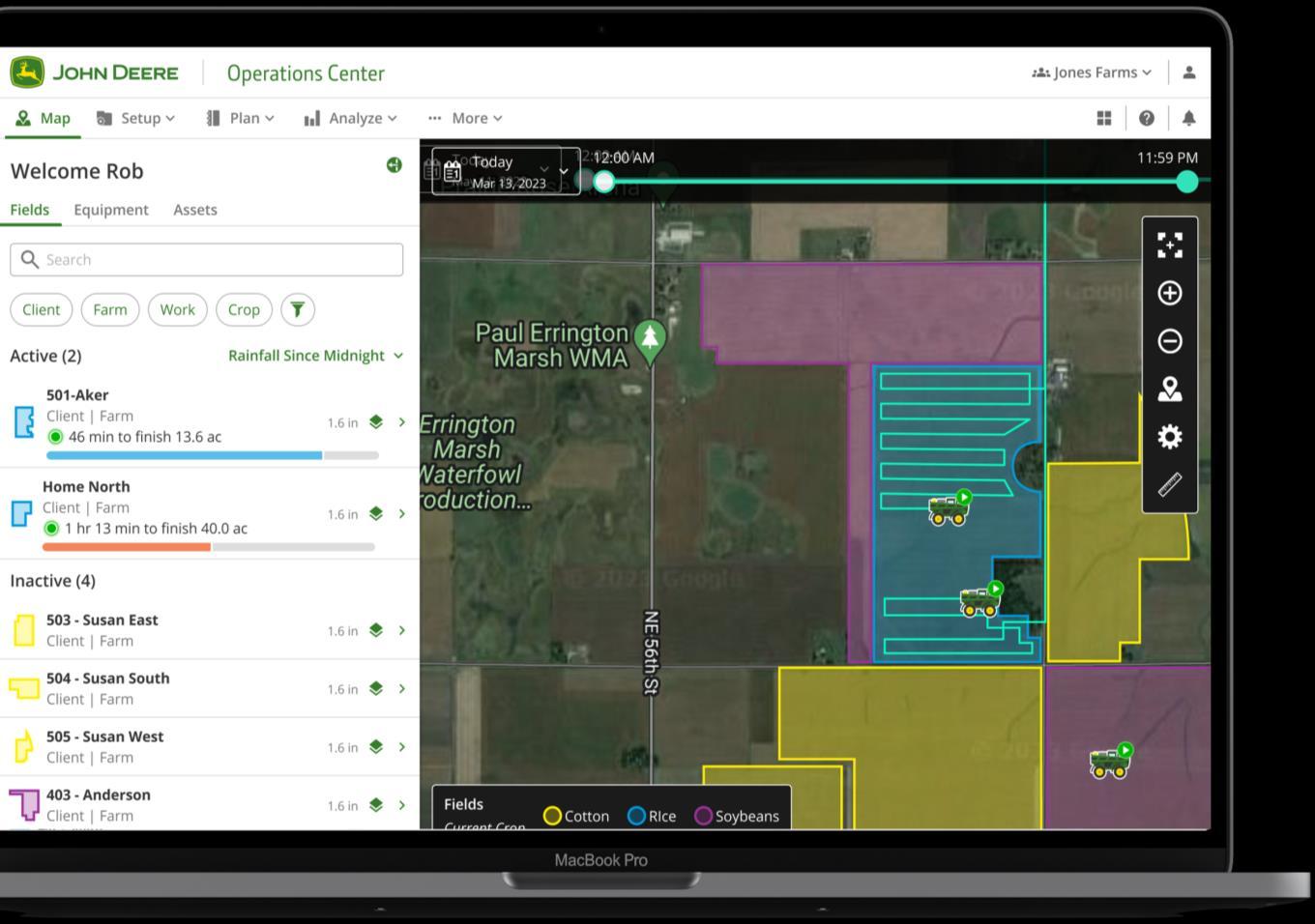
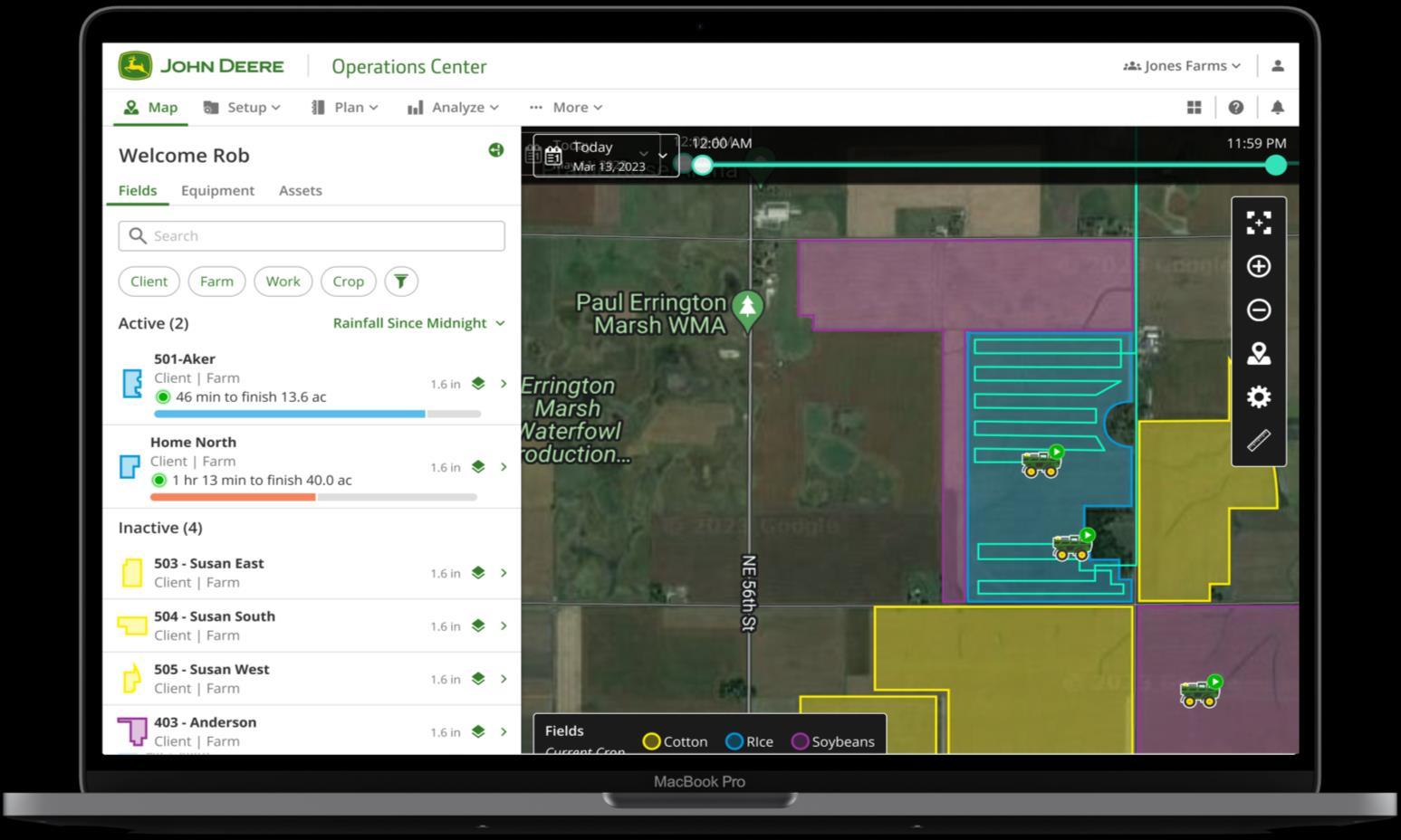
Sprayer Fill Level
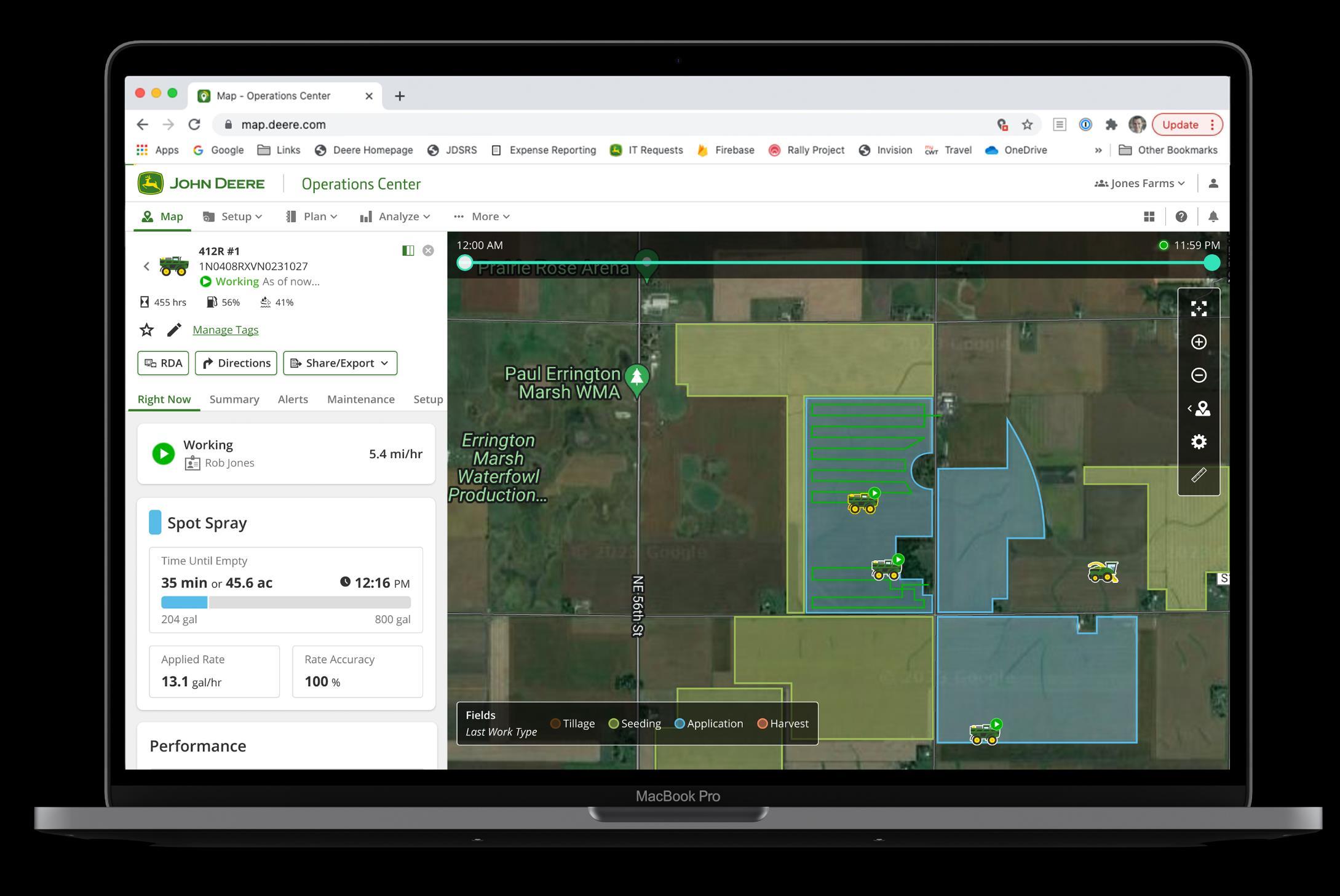
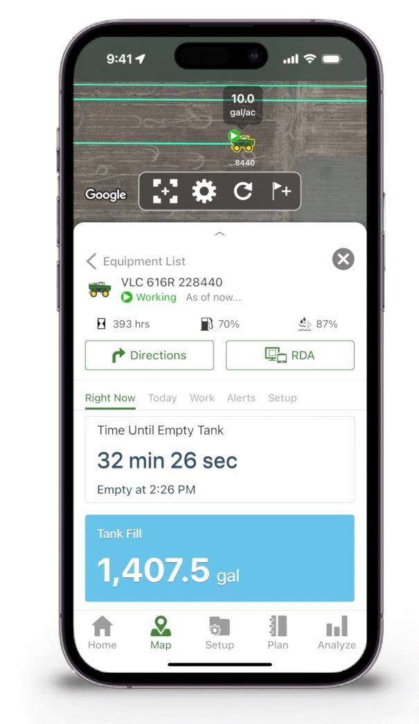
Estimated Time Remaining
For the Operator
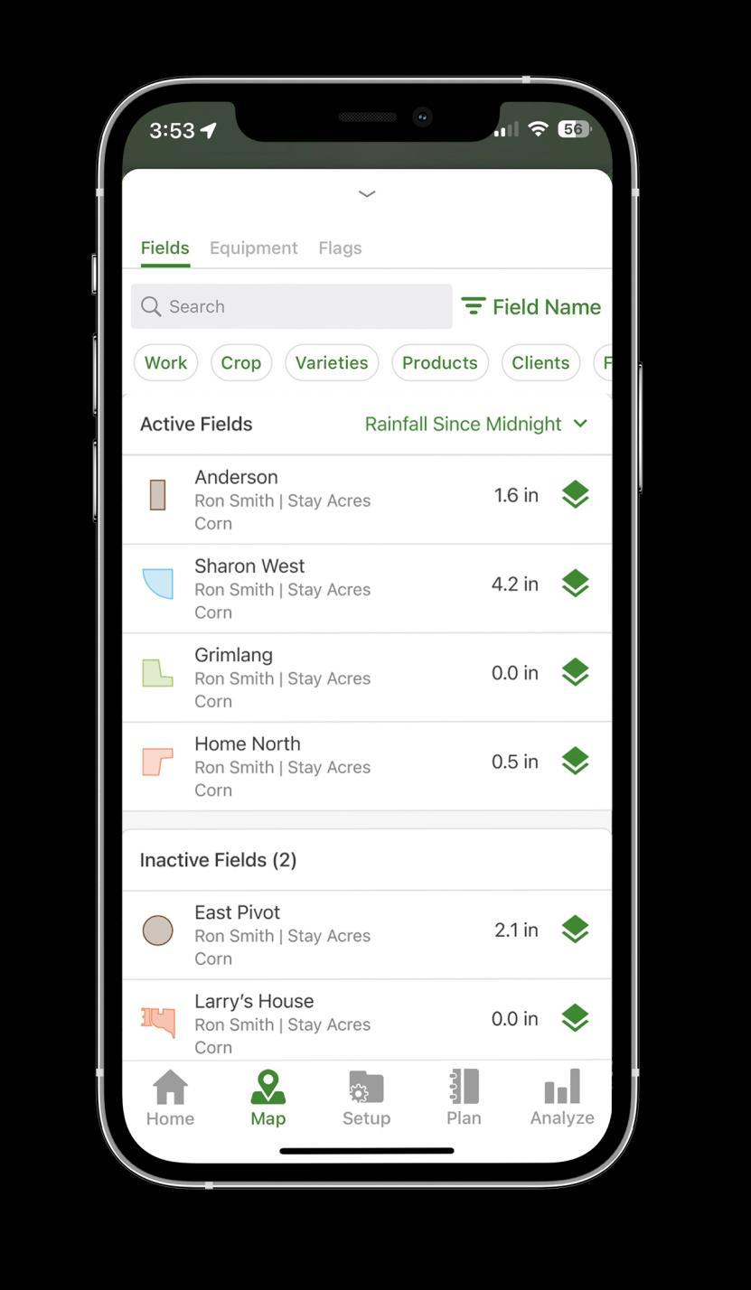
Rainfall Since Midnight
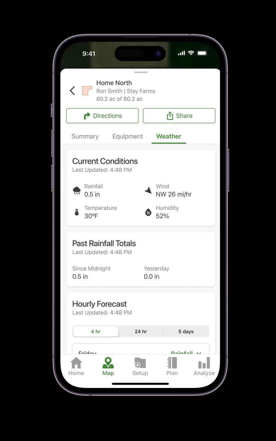
Current Conditions
Past Rainfall
Hourly Forecast
ANALYSIS TOOLS
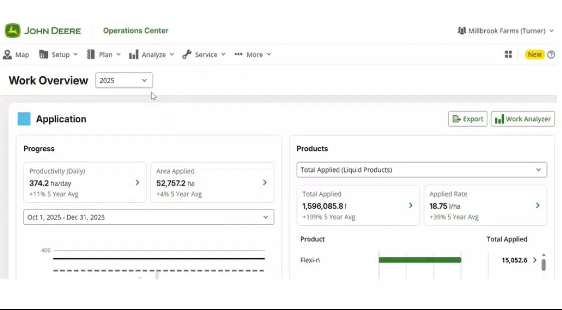
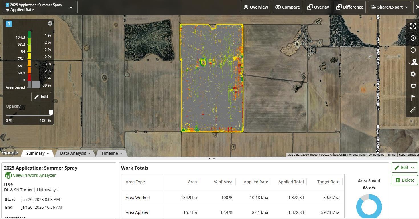
Work Overview
The Starting Point for Smarter Decisions
Overview
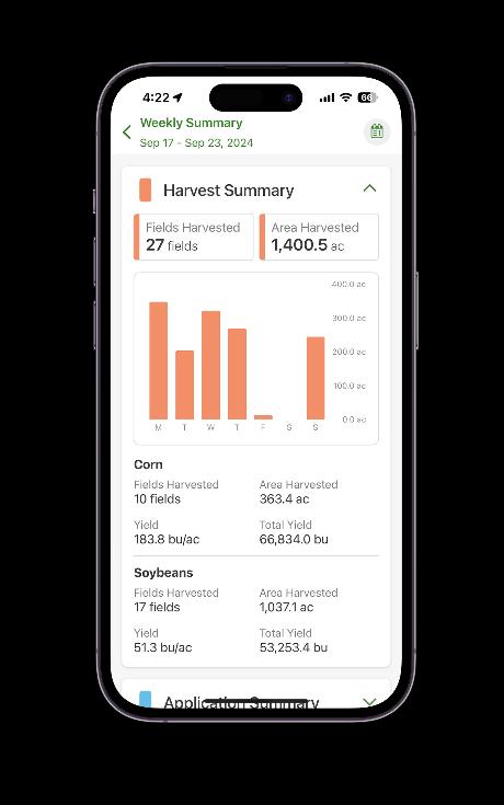
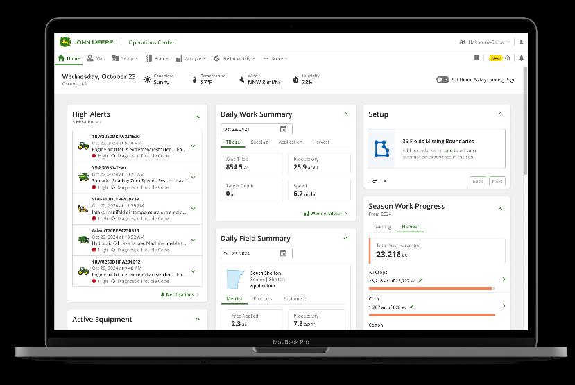
Work Overview is an easy-to-understand dashboard that helps you quickly understand how your harvest is progressing, and your machines are performing.
It simplifies complex data analysis into clear, actionable insights making it the ideal starting point for identifying opportunities and guiding deeper analysis
Here’s How this Helps You
• Easy To Use – Clean and simple dashboard to quickly understand progress and machine performance in just a matter of clicks
• Confidence – Use yield and performance trends to guide next season’s varieties and equipment investments to know that they were smart decisions
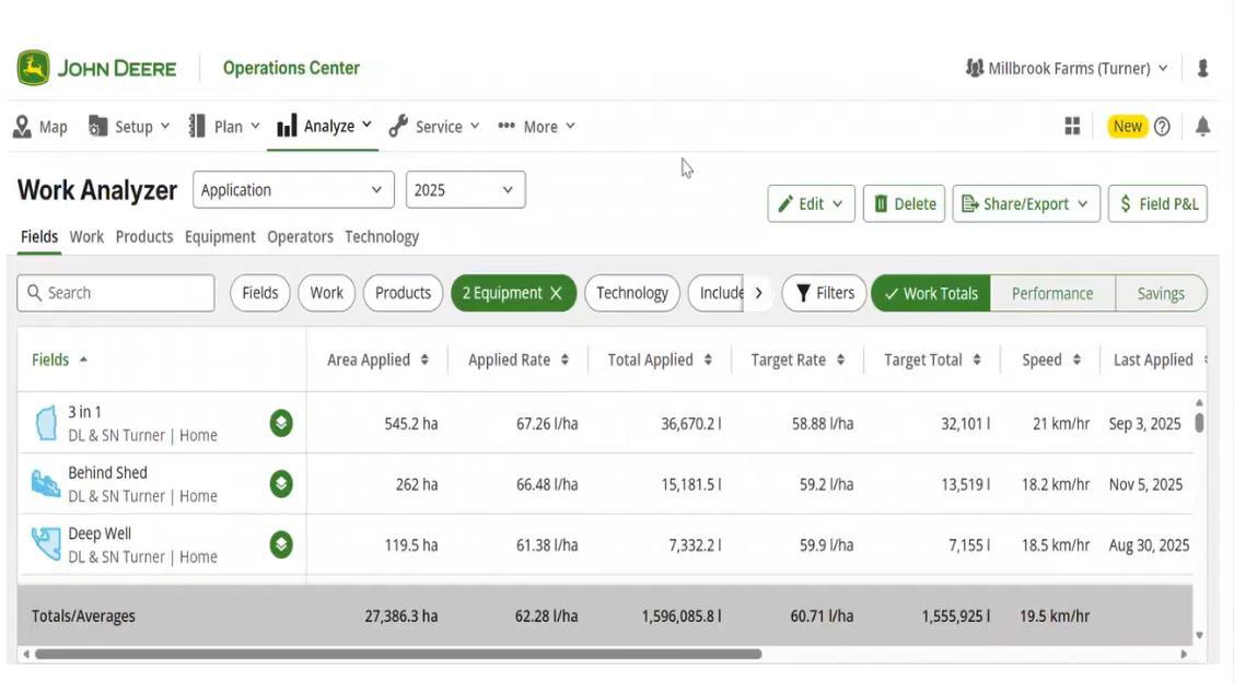
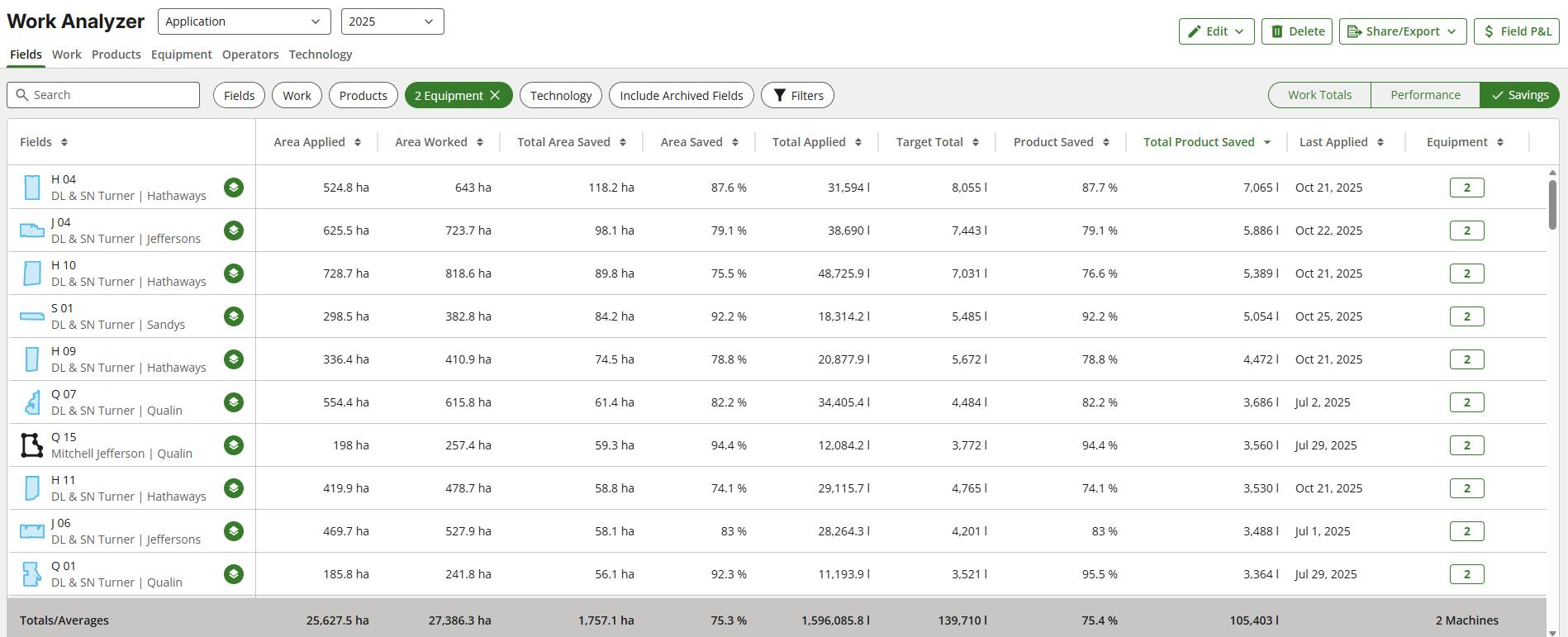
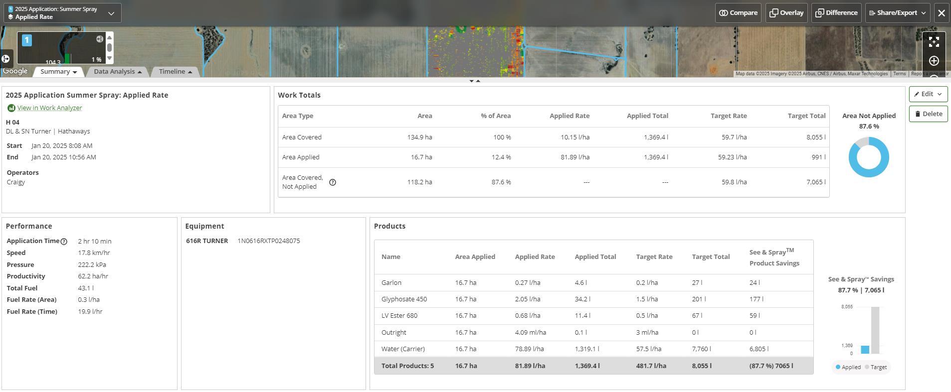
Work Analyzer
Turning Field Data into Actionable Insights
Overview
Work Analyzer provides a clear, visual breakdown of how field work has been completed, helping you understand timing, coverage, and machine performance across every operation.
It turns detailed operational data into simple insights, making it easy to identify efficiencies, spot issues early, and support better on-farm decisions.
Here’s How this Helps You
• Easy to Understand – Simple visuals show when, where, and how work was completed, so you can quickly review operations without digging through raw data
• Better Decision Making – Analyze trends across seasons to improve planning, optimize equipment use, and increase efficiency in future operations
Work Analyzer
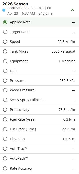
Field Overview
Your Field’s Report Card and it’s Recipe for Success
Overview
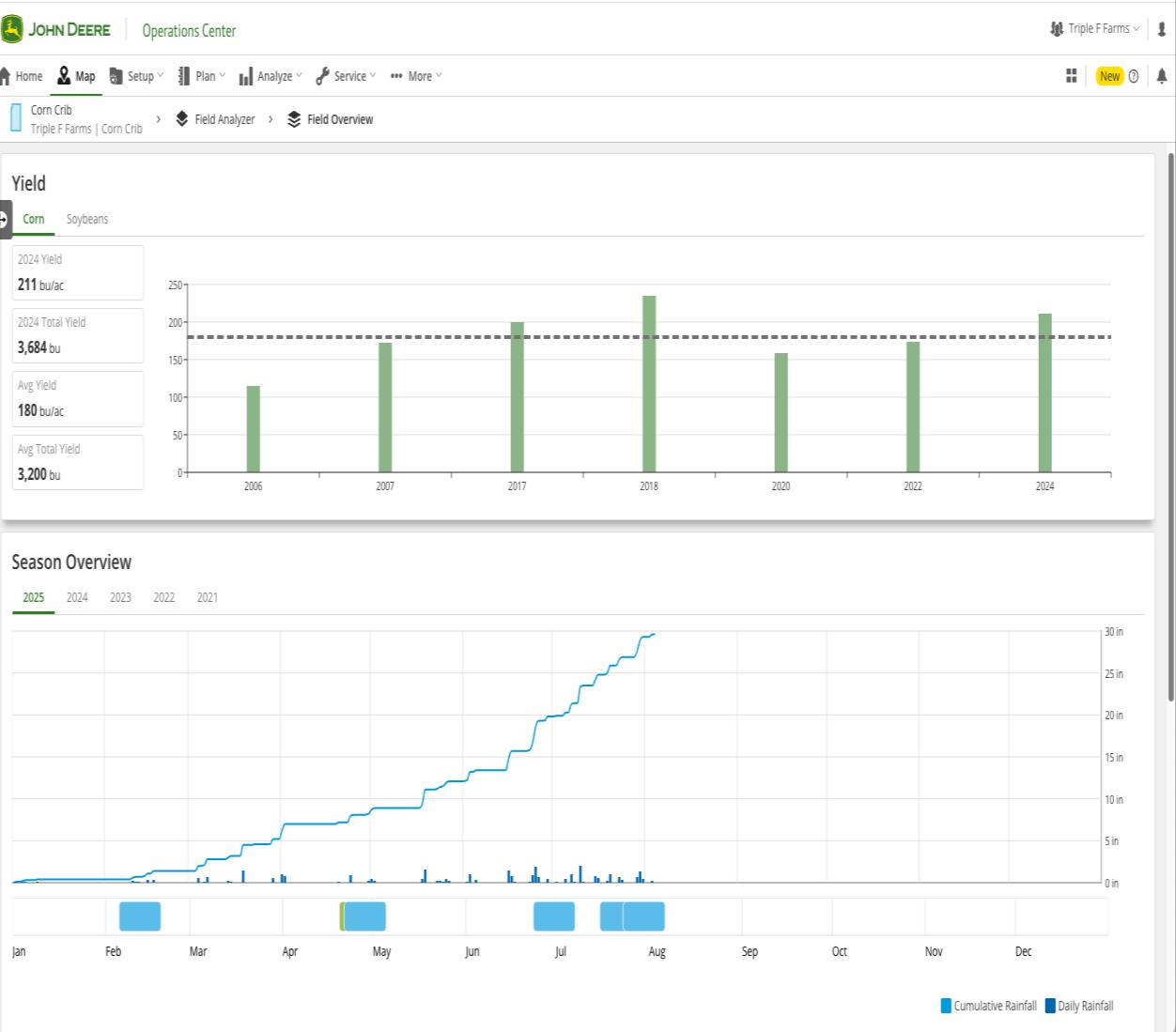
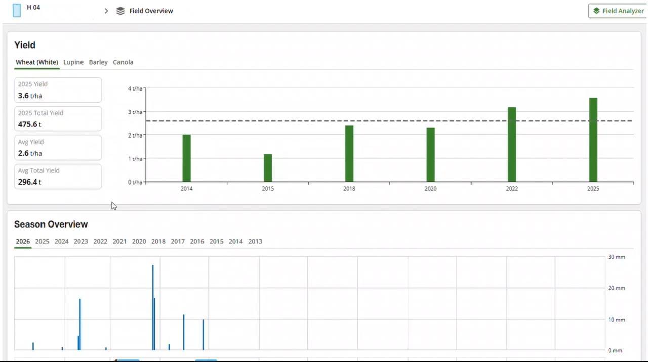
Field specific view of your crops’ performance – and the ability to compare it across seasons.
Field Overview gives a clear snapshot of one crop on one field, showing its performance and how it compares to previous years—without digging through individual records or seasonal summaries.
Here’s How this Helps You
• Better Decision Making–See what worked and what didn’t by viewing yield, variety, weather, and inputs all in one place.
• Time Savings/Ease of Use – Field Overview gives a simple crop snapshot so you can quickly assess results without digging through data.
Field Overview
Data Formats
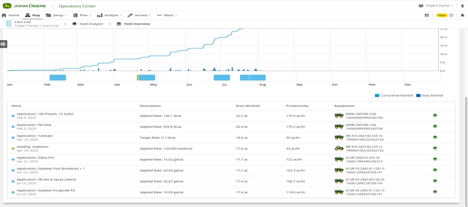
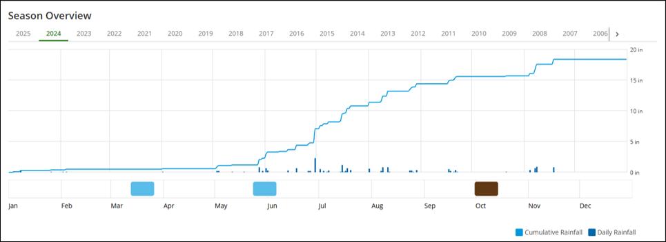
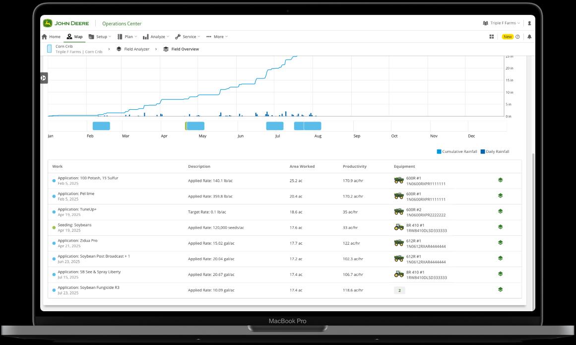
• Season Overview Card
• The season overview card is segmented by season and provides a time-synced season timeline, a work record season timeline, and a work record list. Seasons are selectable for every year that has an available work record.
• The time-synced season timeline combines a daily rainfall bar graph with a cumulative rainfall line graph. The default timeline is one calendar year, 1 January to 31 December. The timeline can be up to two years long starting with the first documented work record for that season.
Field Overview
Field Analyzer
Clarity Across Every Field, Every Operation
Overview
Field Analyzer gives you a clear view of completed work in each field and gives you the ability to analyze performance at a field-by-field level.
It brings together spatial and operational data into one easy view, making it simple to identify variability, compare performance across layers, and uncover opportunities to improve efficiency.
Here’s How this Helps You
• Clear Field Visibility – Easily see where work was completed, how consistently operations were performed, and where adjustments may be needed
• Smarter Planning – Use insights from past seasons to improve field strategies, optimize inputs, and make more confident decisions for future operations
Field Analyzer
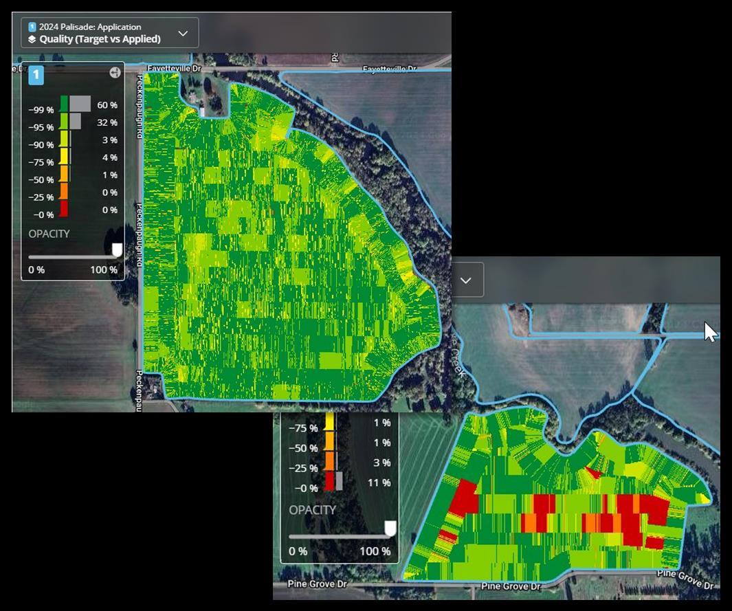
See & Spray
Field Analyzer
See & Spray
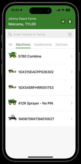
Equipment Mobile
• Simple-to-use mobile app to manage all machines in one place
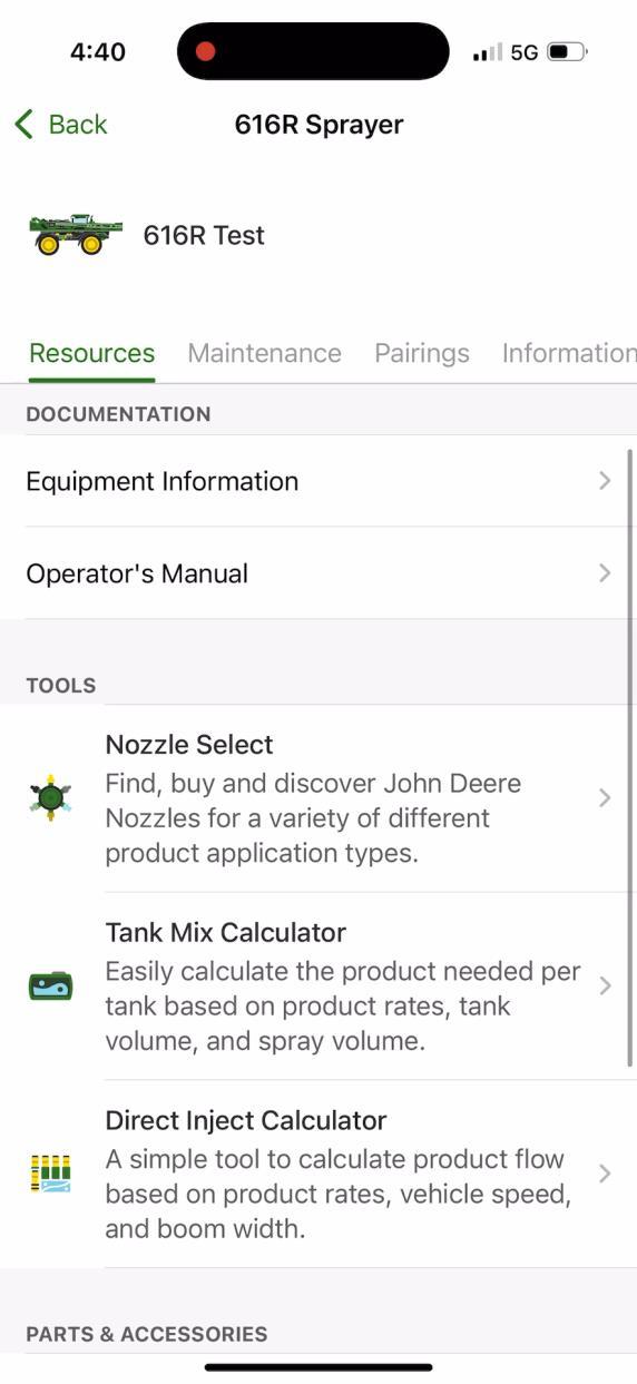
• Searchable Operator’s Manual with AI assistant to quickly find answers in the field
• Operator setup best practices to ensure machines are configured correctly every time
• View and manage maintenance for your equipment list directly from Operations Center
Precision Ag User Guide
A step-by-step guide on how to setup, plan, execute, monitor and analyse