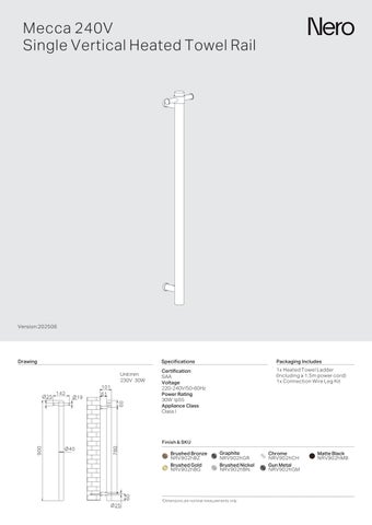
Single Vertical Heated Towel Rail
Version:202506
Drawing
Specifications
Certification
SAA
Voltage
220-240V/50-60Hz
Power Rating 30W Ip55
Appliance Class Class I
Finish & SKU

NRV902hBZ
Brushed Bronze Brushed Gold

NRV902hGR

NRV902hBG

NRV902hBN Graphite Brushed Nickel
Packaging Includes
1x Heated Towel Ladder (Including a 1 5m power cord) 1x Connection Wire Leg Kit


NRV902hCH NRV902hGM Chrome Gun Metal
Safety, Installation, and Care Information
Safety and Installation:
• This 240V heated towel rail must be installed and tested by a qualified electrician in accordance with current local electrical and building regulations.
• Mount the rail on a flat, uniform wall with the base installed at least 600mm above the floor to reduce the risk of accidental contact, particularly by children.
• It is essential that the towel rail is connected to a suitably rated Residual Current Device (RCD) circuit to enhance safety.
• In wet areas, strictly adhere to all electrical guidelines. Avoid installing the rail in locations subject to direct water spray or excessive moisture. It should not be mounted within the shower zone or immediately adjacent to bathtubs and sinks unless additional protective measures, such as splash guards, are implemented.
• When fixing to hollow walls, ensure that suitable anchors are used for a secure installation.
• Do not cover the towel rail with non-ventilating materials (e.g., plastic or waterproof covers), as this could lead to overheating and an increased fire risk.
• Regularly inspect the power cord for signs of damage. If any damage is detected, have the cord replaced immediately by an approved service agent or qualified professional.
• Do not use the towel rail to hang items contaminated with oil, petroleum-based products, or dry cleaning fluids, as these substances can elevate fire risks.
• Never immerse the towel rail in water or any other liquid.
• Ensure that the electrical supply is strictly 240V, 50Hz to avoid potential hazards.
Care Information:
• Always disconnect the power before cleaning the towel rail.
• Clean the unit using a soft, damp cloth with a non-abrasive cleaning agent to preserve the finish. Avoid harsh scrubbing, acidic cleaners, or abrasive products that may damage the surface.
• Periodically check all mounting and electrical connections, and ensure that the unit is well-ventilated to maintain optimal performance and longevity.
Parts Names
Towel rail x1
Support Leg x1
Concealed Support Leg x1
Mounting Bracket x1
Mounting Bracket(For Concealed Installation) x1
Expansion Screw x2
Expansion Plug(E type) x2
Grub Screw x4
Cross Recessed Pan Head Screw x2
Ball Head Allen Key x1
Towel Hanger x1
Grub Screw(With Flat-Tip) х1
Nero Heated Towel Rail/Ladder– 240V IP55 Installation
This guide fo ows the AS/NZS 3000 2018 standard and outlines where a 240V IP55 heated towel rail/ladder can be safely insta led n a bathroom
Understanding IP Ratings
All e ectrical fixtures in bathrooms must meet certa n Ingress Protection (IP) ratings to ensure safety.
• IP55 means:
◦ "5" (Dust Protection) – L mited protect on against dust enough to prevent damage to internal components
◦ "5" (Water Protection) – Can withstand ow-pressure water jets from any d rection (equ valent to IPX5)
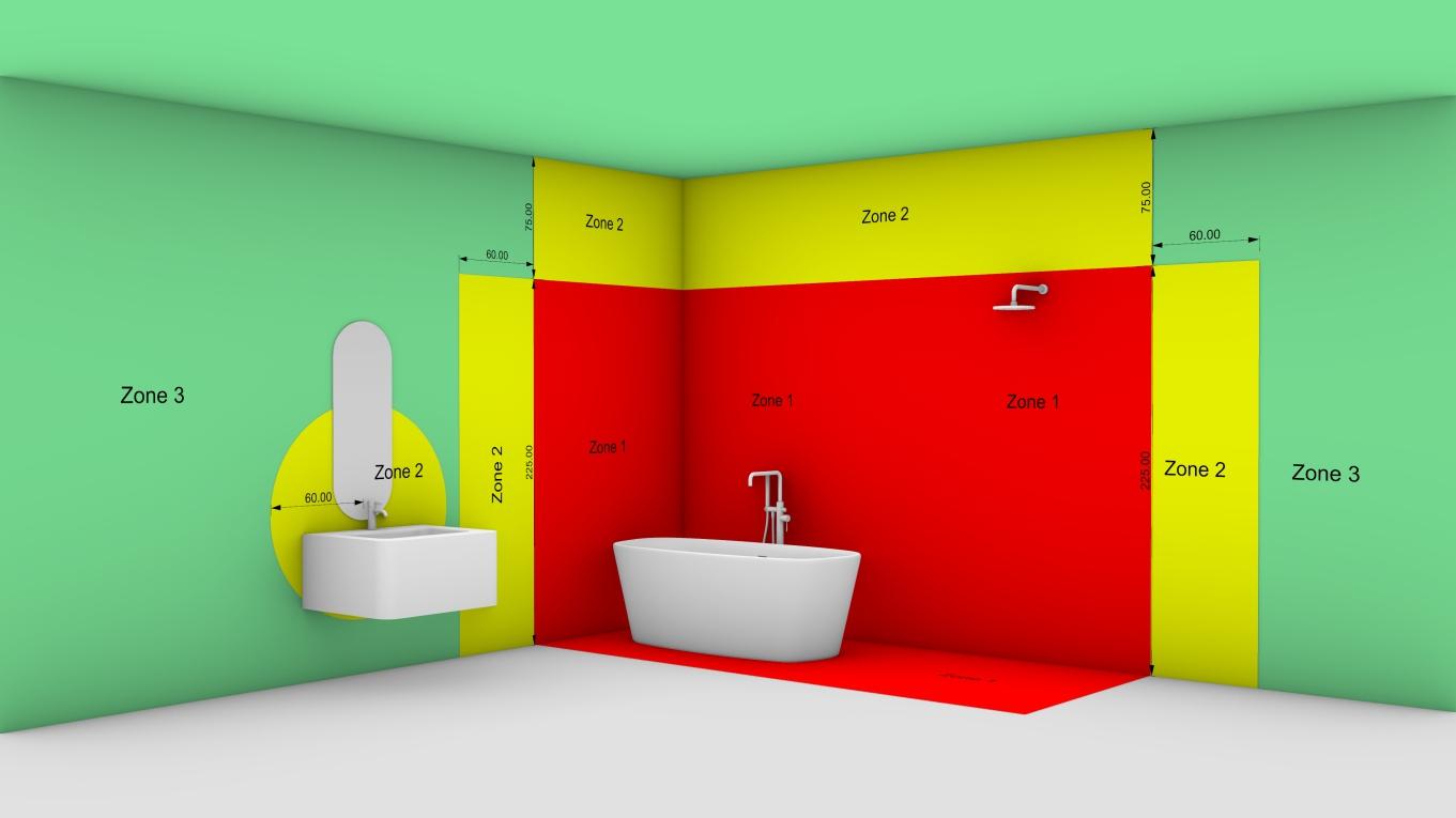
Installation Zones for 240V IP55 Heated Towel Rails/Ladders
Our 240V IP55 heated towel rail/ladder is suitable for installation outside Zone 1 in accordance w th AS/NZS 3000 2018 A ways check with a qua fied electrician to ensure compl ance with loca regu at ons and site-specific condit ons
Important Safety Notes
• A electrical work must be performed by a licensed electr cian
• Hardwir ng s required
• A circu ts must be protected by a 30mA RCD to ensure user safety.
For more details, please contact support@nerotapware com au or call +61 387863170
Illustration A
The expans on screw mounting hole
The power cord conduit ho e
Illustration B
Step 01
Assemble the product following illustration A and B.
Illustration A secure the ② to the upper nut holder of the ① with the ⑨ and slide the ④ into the ② and secure it with the ④
Illustration B: secure the ③into the lower holder of towel rail with ⑧ Then, pass the power cord through the conduit hole of ⑤ tap ⑤ into ③ and secure it with ⑧.
Step 03
Pull out the mounting bases from the towel rail, ④⑤ with on top and on the bottom. Then, overlap ④ ⑤ them individually with the marked outlines on the wall, to mark the drilling positions of mounting holes and power cord passage hole.
Step 02
Place the ① squarely against the wall and draw the outline of the two bases individually with a wipeable marker.
Step 04
Use a φ8 drill bit to drill holes at the marked position. The recommended depth for the mounting hole is 50mm, while the passage hole should go through the wall. 50 mm
Illustration D
Step 05
Tap the expansion plugs ⑦ into the mounting holes sequentially, flush them with the wall surface.
Illustration C
Step 06 Secure the to the expansion plugs with ⑥
Illustration E
Step 07
Illustration C: Slide the ⑪ into the upper end of the product, and secure it with the ⑩in a proper position
Step 08
Illustration D & Illustration E Pass the power cord through the conduit hole of the lower mounting base and connect the power cord to the controller. Then, slide the towel rail into the mounting bases and secure it with ⑧ The installation is completed.