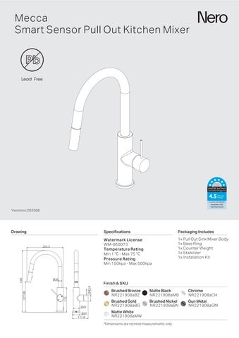
Mecca Smart Sensor Pull Out Kitchen Mixer
Versions:202506
Watermark License WM-060073
Temperature Rating Min 1 ℃ - Max 75 ℃
Pressure Rating Min 150kpa - Max 500kpa


1x Pull Out Sink Mixer
1x Base Ring
1x Counter Weight
1x Stabilizer
1x Installation Kit
NR221908aBG Brushed
NR221908aBZ

NR221908aBN Brushed

NR221908aCH

*Dimensions are nominal measurements only.
INSTALLATION INSTRUCTIONS
GENERAL INSTRUCTIONS:
- Th s product must be nstalled by a licensed plumber in accordance with oca regu ations and plumbing codes
- Before installation, the water supply nes must be flushed thorough y to remove debris such as sand, wood shav ngs, or metal particles that could damage nterna components or block the fi ters
- The ambient temperature must remain above 0°C during insta at on and operat on In colder condit ons appropr ate anti-freeze precautions must be taken to prevent damage as frozen hoses may rupture and cause leaks or water damage
- Four high-quality AA alka ne batteries (LR06) are requ red, preferably from the same brand and batch Batter es must not be mixed between o d and new, and the polarity should always be correctly observed
- Alternatively, the product may be powered us ng a certified AC adapter with an nput of 100–240V and output of 6V 1000mA
- Before performing any nstallation or ma ntenance on the so enoid unit, the power supply whether battery or AC must be d sconnected When using the AC adapter, ensure t is plugged nto a stable and protected power source
INSTALLATION OVERVIEW
SPECIFICATIONS
Product Name Mecca Smart Sensor Pu Out K tchen M xer
Power Supp y DC: 4 AA alka ne batter es(LR06x4) AC 100~240V/6V-1000mA Power Adapter(Optional, SKU: NRPA407)
Operat ng Water Pressure 150 kPa - 500 kPa
Water Temperature ≤ 75°C
Sensor Range 8 cm ±10% (tested on wh teboard)
Act vation Time ON ≤ 1s / OFF ≤ 1.5s
Auto Shut-Off 30 ±10% seconds
Inlet Size
G1/2 (DN15)
Power adapter is optional and not included n the package.
1. Insert all 4 braided hoses through the mounting hole on the benchtop, ensure the diameter of the mounting hole > 35mm.
2. Slide the decorative ring and base gasket onto the M34 threaded pipe. Insert pull-out hose and sensor cable through the mounting hole. Connect red/blue hoses to “H”/“C” inlets respectively.
INSTALL THE SOLENOID
1. Drill 2 holes on the wall (Ø6mm, 60mm apart).
Insert expansion plugs, fix mounting bracket to wall with screws. Mounting Bracket Screw
2. As shown in the diagram, clip the solenoid into the mounting bracket and ensure it is securely installed.
3. Connect the small flexible hose to the smaller port, and the remaining hose to the other port.
4 Insert stabilizer, rubber washer, metal washer, and locking nut into the threaded pipe of the mixer from the underneath of the basin and tighten the locking nut with Phillips screws to secure the mixer.
1. On the left side of the solenoid, press the battery holder and rotate knob counterclockwise to eject.
2. The battery holder ejected.
3. Insert the batteries into the battery holder, making sure the orientation matches the diagram.
4. Reinsert the battery holder into the box until it clicks into place.
1 C ip the mesh filters into the washers, them insert them into the nuts of red/blue hoses(Ensure the orientation of the mesh filters and washers match the diagram)
Connect hoses to the respective hot/cold angle valves and tighten
2. Connect flexible hose and small flexible hose to G1/2 and G3/8 inlet ports on solenoid respectively and tighten them securely
3. Connect pull-out hose to quick-connect port on solenoid
4. Attach the counterweight to the pull-out hose.
5 Connect sensor cable to the plug of solenoid (ensure the arrows are aligned), tighten the nut on the plug to secure the connect on
6. Connect the power adapter to the solenoid power port
INSTRUCTIONS FOR USE
ADJUST THE SENSOR RANGE
1. Bring the magnet close to the sensor indicator light.
2. When the light blinks rapidly, hold your hand at the desired sensing range.
3. When the blinking stops, the new range is set.
Note: The magnet is not included in the package.
FUNCTION INTRODUCTION
• Rotate handle left/right to adjust water temperature.
• Lift or lower the handle to turn water ON/OFF.
MAINTENANCE AND CARE
• Wipe the sensor window with a soft cloth if it is not working properly.
• Replace the batteries if needed(If the red light blinks in the sensor window)
• Use a soft, damp cloth to clean the tap.Do not use harsh or corrosive detergents.
• Clean filter every 6 months or when water flow slows.
STEPS TO CLEAN THE FILTER
1. Turn off the mixer hand e. 2 Turn off the angle va ves. Unscrew red/b ue braided hoses and remove filters. Clean with a brush and reinstall
• Pull-out spray head extends ≤ 30cm for flexible cleaning.
• Swivel neck rotates 180°, 90° left and right.
• Sensor Activation: When handle is OFF, wave once to turn ON, wave again to turn OFF. Water auto shuts off after 30 seconds if no further motion is detected.
3. For G1/2 braided hoses remove, clean the filter, reinstal and tighten.