4 minute read
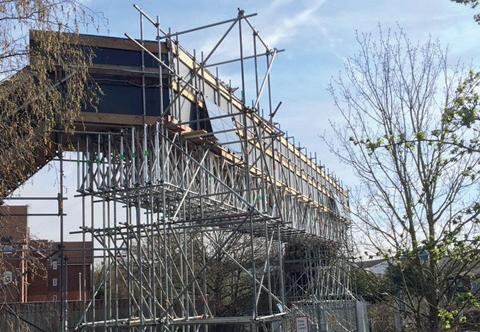
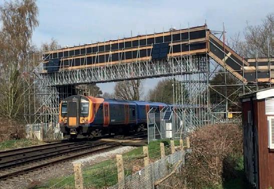
Scaffolding above and around live railways

from AccessPoint Issue 02
by AccessPoint
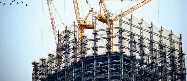
Increased infrastructure spending is creating new opportunities and challenges for the access and scaffolding sector. Ivik Masek, from design consultants 48.3, offers guidance about scaffolding design close to railways.
When designing a scaffold structure in the vicinity of railway tracks, aerodynamic actions (buffeting loads) from passing trains are a critical consideration. This guidance compares the methods used in BS EN 1991-21 and GC/GN56122 to determine the pressures on a scaffold bridge over railway tracks.
Aerodynamic actions from passing trains
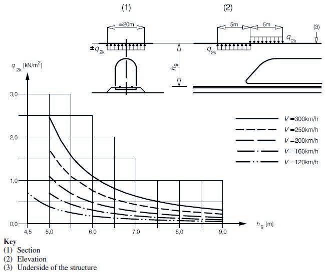
A train traveling at a speed of 120 km/h generates an aerodynamic pressure field which it imposes on scaffold structures alongside and over the track. The graph shown in Figure 1 is limited to line speeds between 120 km/h and 300 km/h. It is important to note that line speeds below 120 km/h also generate pressures on scaffolds and the vertical distance hg is often < 4.5 m. The imposed loads defined in BS EN 1991-2 are intended to be used for the design of new bridges and not temporary bridges that encroach the minimum required headroom of 4.5m. The designer therefore must extrapolate the graph to determine the pressure loads ±q2k
Difference in values between methods
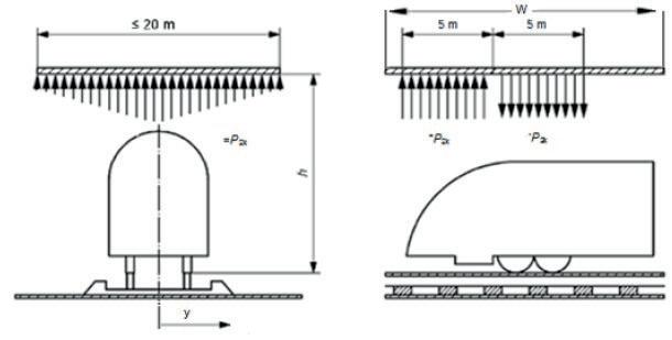
Method A – BS EN 1991-2 clause 6.6.3 a dynamic amplification factor. The value of ±q2k should be multiplied by 2.0 in the 5.0 m zones. k1 = 1.0 Class 66 locomotive k1 = 0.85 Class 158 leading vehicle k1 = 0.6 Class 390 leading vehicle
For trains passing each other in opposite directions, the actions should be added, i.e. the total of both calculated values of ±q2k for each train.
The values in Figure 1 apply to trains with an unfavourable aerodynamic shape where k1 = 1.0. The Eurocode states the following reduction factors may be used: k1 = 0.85 for trains with smooth-sided rolling stock and k1 = 0.6 for streamlined rolling stock.
The k values are derived from test results for each structure type and typical examples are given in Figure 2.
Figure 2: Typical examples of train types and related k values.
Method B – GC/GN5612 clause G 3.5
The values of ±q2k are determined using a graph shown in Figure 1. Note that the loaded width for the structure considered extends up to 10.0 m to either side of the track.
The elevation (2) in Figure 1 shows the pressure field caused by a moving train which it imposes on structures above the tracks for a length of 5.0 m. It is applicable at the start and end of a structure and defined as
Key differences: The actions ±q2k in the Rail Safety and Standards Board (RSSB) guidance are determined using an equation. The equation contains three variables, h, W and y, which allow the designer to identify pressure loads below the 4.5 m vertical distance and on structures < 10.0 m wide. The pressures over the track can also be reduced by the lateral distance y either side of the track.
The shape parameter of the train k2 used in this method are 1.0 for bluff trains (unfavourable aerodynamic shape) and 0.432 for intermediate (smooth-sided rolling stock and streamlined trains).
Design example
We consider the aerodynamic actions on a temporary 1.85 m wide pedestrian footbridge over two tracks with a line speed of 75 mph (120 km/h). Both trains are Class 158 and the vertical distance hg from the running surface of the track to the underside
References
1) British Standards Institution (2010) BS EN 1991-2:2003 – Eurocode 1: Actions on structures – Part 2: Traffic loads on bridges, London, UK, BSI.
2) Rail Safety and Standards Board Limited (2014) GC/GN5612 – Guidance on Loading Requirements for the Design of Railway, London, RSSB.
Worked example using Method A
The value of the action ±q2k is given in Figure 1 where: hg = 4.5 m. Dynamic amplification factor = 2.0.
V = 120 km/h. The Maximum Design Speed and should be taken as the maximum line speed at the site.
Reduction factor k1 = 0.85 for trains with smooth-sided rolling stock. For trains passing each other in opposite directions (±q2ak) + (±q2bk).
±q2k from Figure 1 = ±0.7308 kN/m2
Therefore, the vertical design load for aerodynamic actions (±q2ak) = 0.73 kN/m2 x 2.0 x 0.85 = ±1.24 kN/m2
Total design load (actions added) = ±2.48 kN/m2 .
The worked examples shown in Box A and Box B illustrate the difference in magnitude of the design loads. Although Method B offers many design advantages associated with reduced live loads, the designer should consider the risks associated with this method. The aim is to design economical scaffold structures with sufficient safety against collapse.
The reader is advised to refer to the full Standard/Guidance for further information.
FIND OUT MORE
Ivik Masek Principal engineer and director
48.3 Scaffold Design Ltd www.483scaffolddesign.com

Worked example using Method B
The pressure loads are determined from equation p2k=0.5ρv2k-
2Cp2(h,W,y) where:
Cp2 = characteristic pressure coefficient
Cp2(h,10,0) = ±((5.5/(h−1.9)2)+0.1) h = 4.5 m. Distance from top of rail to structure over the railway. k2 = 0.432. Shape parameter of the train. ρ = 1.225 kg/m3. Density of air. v = 33.33 m/s. Train speed of 120 km/h.
W = 1.85 m. Along track width.
Y = 0.0 m. Lateral distance from the track centreline.
Therefore, Cp2(h,10,0) = ±((5.5/(4.5−1.9)2)+0.1) = ±0.91 kN/m2
Using the calculated value for Cp2(h,10,0), the variation with structure width, W, for bluff, intermediate, and streamlined trains is respectively given by:
Cp2,bluff(h,W,0) = (0.025W+0.75)Cp2(h,10,0) = (0.025 x 1.85 + 0.75) x 0.91 kN/m2 = 0.72 kN/m2
Cp2,int_str(h,W,0) = 0.51Cp2,bluff(h,W,0)), for 1.5 m ≤ W ≤ 3.0 m = 0.51 x 0.72 kN/m
Apply dynamic amplification factor 2.0 and combine actions for trains passing.
Total design load = ±0.44 kN/m2 .
An assurance of quality and performance
Regulating quality and high safety standards Independent audit regulates members Audit exceeds PAS 91
Matching members with new clients