2 minute read
UNDULATING PAVILION

KINETIC TRANSFORMATION PAVILION
Undulating Pavilion 02
Advertisement
Kinetic Transformation Pavilion
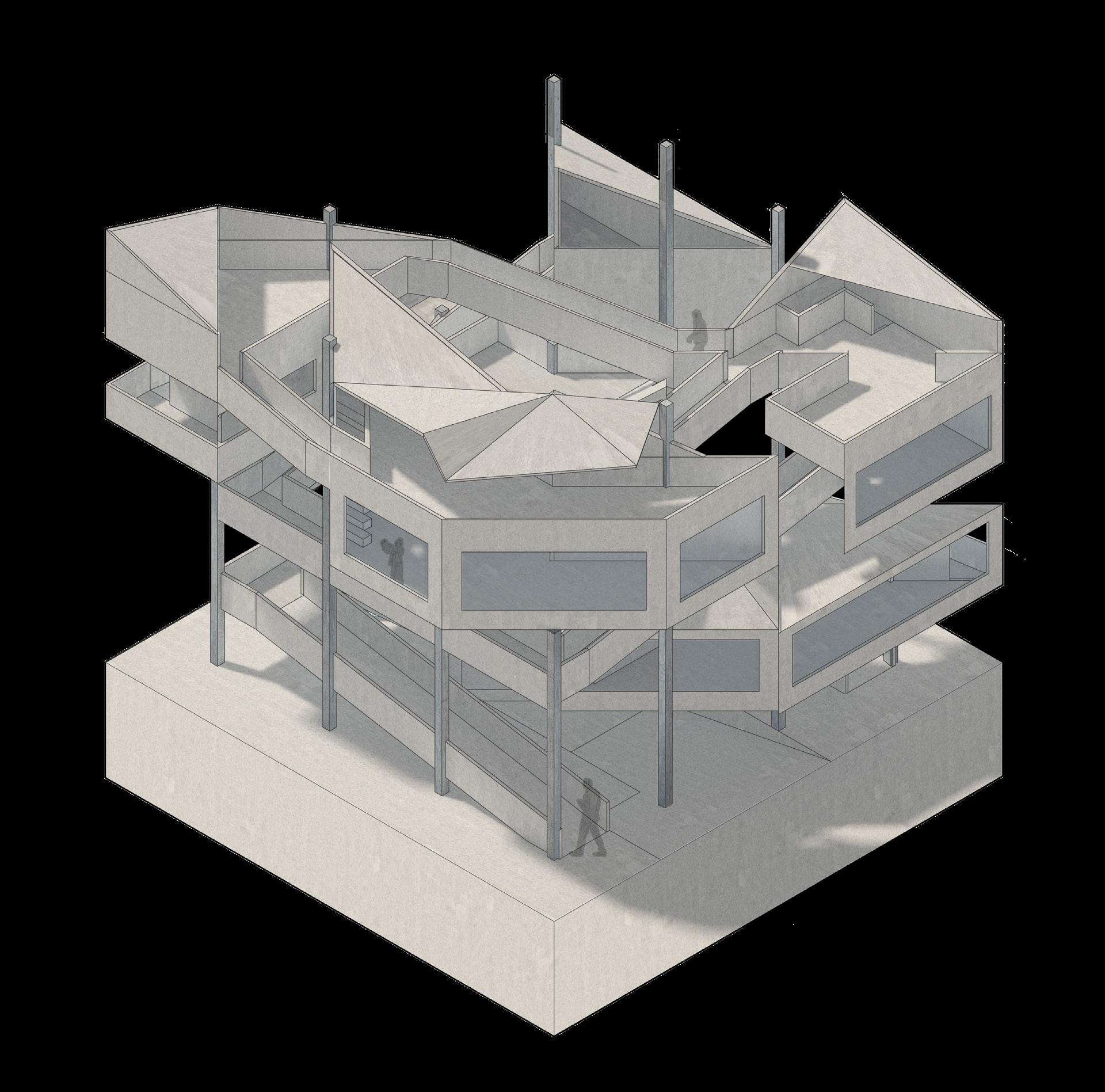
Using the Burke Brise Soleil as the principal inspiration and precedent study, this project envisions the creation of a pavilion with dynamic facades. The project consists of multiple key elements and systems that facilitate the kinetic nature of the pavilion. The fin system as well as the series of mechanisms designed by our group allow for the kinetic fin system to function and therefore for movement to occur. The kinetic fin facade functions to move upwards and outwards via a rotating arch that meets the fins and thus pushes them upwards. The fins mold to the shape of the arch as they’re pushed upwards, creating a tunnel-like space. The kinetic wall facade could be closed or open at any degree necessary up until its maximum opening of 45 degrees. The extension of the project (02.B) consists of manipulating this kinetic facade onto a multipurpose fence.
*Work done in collaboration with Huzaifa Chughtai and Abdelrahman Merdan consists of physical model-making, and pavilion design. Some Drawings and night render were done jointly with Huzaifa, and the rest was done by me.
Arch in a Lowered Closed State - Actuator Contracted
The structure’s components (Arch and Fins) move through its main kinetic system of a hydraulic actuator. The hydraulic actuator is suspended from the ceiling of the pavilion and is connected to the arch in its lowered resting state. In a contracted state, the actuator keeps the arch lowered which in turn keeps the fins lowered. However, Once the actuator extends, it pushes the arch outwards which in turn lifts and raises the fins.


Arch in a Rotated Outwards and Raised State - Actuator Extended

LEGEND:
1. Connector
2. Connector Rod


3. Ball point
4. Ball point joint
5. Screws
6. Extension Tube (Inner tube - Shortened for diagram purposes)
7. Small tab to connect Pressure canister
8. Pressure canister
9. Outer Tube
10. Hinge Joint
11. Mechanism wall attachment
12. Bolts
(A): Isometric of fin hinge mechanism

(B): Exploded Isometric of fin hinge mechanism

(C): Isometric and exploded isometric diagrams of arch-wheel mechanism
LEGEND:
1. Bolts
2. Connector
3. Hinge component ( Attached to Connector)


4. Hinge component (Rotates to allow raising of fins)
5. Hinge slider (Slides on hinge component to accomodate for fin raising)
6. Bolts
7. Fin Mechanism attachment
8. Segment of fin
Above: Perspective of Fin mechanism in lowered state (closed)

Below: Perspective of Fin mechanism in raised state (open)

1. Pad attaching hinge mechanism to fin
2. Fin mechanism attachment
3. Bolts
4. Fixed rod (Allows rotating hinge to rotate around it)
5. Rotating hinge joint component
6. Fixed hinge joint component
7. Flat pad attaching hinge mechanism to connector
8. Bolts
9. Connector (connects hinge mechanism to structural pipe from where it hangs)
(A): Exploded Isometric of hinge mechanism

(B): Isometric of hinge mechanism
Above: Perspective of Fin mechanism in lowered state (closed)


Below: Perspective of Fin mechanism in raised state (open)