




HONDA CIVIC HYBRID
Faulty inverter stops charge
MERCEDES-BENZ S400
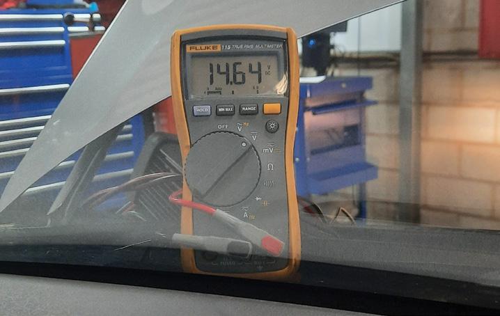
A/C niggle, electrical mayhem
AUDI Q5
Blocked drains, big trouble
FORD RANGER Vacuum gone AWOL











Editorial Board
Geoff Mutton
Jeff Smit
Technical Editor
Jeff Smit
Sub-Editor
Cameron McGavin
Scan Data Director
Rod Maher
Technical Research
Brendan Sorensen
Technical Contributors
Brendan Sorensen
Mark Rabone
Frank Massey (UK)
Jack Stepanian
Sam Nazarian
Jason Smith
Clinton Brett (Diesel Help)
Technical Assistance Team
Deyan Barrie Andrew Kollosche
Sideth Chiv Maurice Donovan
Gil Sher Anthony Tydd
Wayne Broady Jason Smith
Marty Hosie Jack Stepanian
Mark Rabone Rob Romano
Daniel Armer Jack Mackay
Gary O’Riain Scott Thomas
George Anagnostoudis
Associate Team Members
Gary Homan Peter Hinds
Columnists
Geoff Mutton (TaT Biz)
Advertising Enquiries
Paul Woods,
National Advertising Manager
E: pwoods@tat.net.au
Ph: 0494 044 958
Graphic Design
Brigid Fraser
E: production@tat.net.au
PH: 0413 009 122
Affiliated Associations
AAAA – info@aaaa.com.au
Capricorn Society Alliance Supplier
VASA – secretary@vasa.org.au



• TaT’s a fact • TaTassist • TaT Share
• TaT train • Tat Biz • TaT SD (Scan Data)
• TaT programs • TaT reviews
• TaT check • TaT find are all trade names of The Automotive Technician Pty Ltd
Automotive Technician


Brendan Sorensen
Ileftthe Australian Auto Aftermarket Expo (AAAE) thinking about how much of the workshop conversation has shifted from individual components to whole vehicle systems.
Steering and suspension used to be work where most of the visible movement was right there in front of you. You could look at a rack boot, a control-arm bush, a ball joint, a shock absorber or a wheel-alignment report and have a fairly direct discussion about what the vehicle needed.
That has not disappeared but it’s no longer the whole picture. The steering rack may still turn wheels yet the way the vehicle decides how much assistance to provide, how much road feel to simulate, how the lane system intervenes or what happens after a steering-angle sensor calibration is now tied into a much wider network of modules and software decisions. Steer-by-wire takes that further. Once the mechanical link is removed, the job becomes a safety-critical control system that needs powersupply integrity, redundancy, correct calibration and proper fault handling. Suspension is heading the same way. A suspension complaint on a late vehicle may not simply be a failed shock absorber. It could be a height-sensor issue, a control-module fault, a 48V actuator supply problem, a communication issue or a calibration that was skipped after mechanical work. The workshop still needs the same trade judgement it always did but the first inspection now has to include a broader question – what system am I actually disturbing by doing this repair?
Steering and suspension are still very physical systems but they now sit in the middle of diagnostics, programming, advanced driverassistance system (ADAS) calibration and customer expectation. A wheel alignment after a suspension job is easy enough to explain. Explaining why the camera, radar or steering system also need attention takes more confidence, especially when the customer thought they were only booking in for a knock in the front end.
Our second spotlight this edition, workshop management, is changing as well, although the tools look different. Artificial intelligence (AI) is the obvious example. Here at The Automotive Technician (TaT) we have been over the moon to see Tech Tina being used habitually by workshops around the country. What has been most pleasing is seeing members realise she is not only there for the problem car on the hoist. She can help structure a diagnostic plan, compare likely causes, turn a rough fault description into a better starting point or – in the office – give a quick training-style explanation when anyone
in the business wants to understand a system before diving in. Or the classic example –turning a chicken scratch job-card notes image into a professional invoice story.
That is how you turn AI into a valuable partner rather than an oracle that’s expected to solve every problem from a three-word prompt. A busy workshop does not always need a magic answer. Often it needs a better first question. If Tina can help a technician slow down for two minutes, capture the right data, think about the system architecture and choose a sensible first test, that can be enough to stop the job heading down the wrong road. The same applies to business questions. Ask her to help think through a workshop process, a customer explanation, a training plan for a junior tech or a way to improve how information is recorded on a job card.
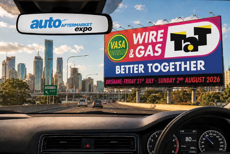
With AAAE now in the rear-view mirror, our attention is firmly on Wire & Gas 2026. Automotive Air Conditioning, Electrical and Cooling Technicians of Australasia (VASA) and TaT are co-hosting this year’s event at The Westin Brisbane from Friday, July 31 to Sunday, August 2 and the theme says it well – Better Together.
There will be the Friday cocktail party and trade show, training sessions, panel discussions, a Gala Awards Dinner and more opportunity for face-to-face technical conversation than you will get from a month of scrolling online. The training mix is strong too, covering AdBlue Selective Catalytic Reduction (SCR), Modern HVAC, Vehicle Security Systems, Electrified Diagnostic Triage, Electric Vehicle (EV) and Hybrid Market Direction, Workshop Productivity and Industry Cohesion.
Bring your swimmers. I gave the heated pool a decent workout at the 2024 event and the swim-up bar will not hurt the argument either, especially for those coming up from the southern states looking to shed the winter woolies.
You do not have to be a VASA or TaT member to attend but members receive discounted tickets, so it is also a good excuse to join one of these growing communities of like-minded workshops. If you run a workshop, send a key technician. If you are the key technician, bring the boss.
Wire & Gas has been going from strength to strength and with VASA and TaT putting our weight behind making it Better Together, this is the year to get yourself in the room.


Jeff Smit
workshops across Australia and New Zealand are under more pressure than ever to run efficiently, stay profitable and keep up with increasingly complex vehicle repairs.
Success is no longer just about turning spanners well. It now depends on how effectively a business manages bookings, quoting, parts supply, technician workflow, technical information and customer communication. As a result, modern workshopmanagement tools are rapidly shifting from optional extras to essential business systems.
At their best, these platforms do far more than replace paperwork. They connect the front counter, workshop floor, parts department and back office, giving workshop owners and service advisers a clearer view of daily operations.
Instead of relying on whiteboards, notebooks or staff memory, workshops can manage booking diaries, digital job cards, quotes, invoices, stock, customer records, reminders and accounting links from one system. Many providers also offer cloud access, mobile functionality and integration with technical data or parts catalogues, which better reflects how workshops now operate.
One of the biggest gains is visibility. In a workshop using disconnected systems, information can easily get lost or delayed. That often leads to missed upsell opportunities, poor communication with customers and wasted time on the floor.
A modern management platform gives staff a live picture of bookings, work in progress, labour allocation, overdue parts and outstanding invoices. That makes it easier to spot bottlenecks and keep jobs moving. Products such as MechanicDesk, Auxo Workshop, Workshop Software and Megabus Marlin are all built around this kind of workflow control.
This visibility helps reduce the hidden waste that quietly drains productivity. Time is lost when technicians are waiting on authorisation, advisers are chasing vehicle history or parts staff are manually checking stock and order status.
Digital booking diaries, centralised job files and automatic reminders help cut those delays. Features that may seem administrative on the surface, such as drag-and-drop bookings, SMS or email reminders,

online bookings and low-margin alerts, can make a direct difference to workshop throughput and profitability.
The second major benefit is stronger financial control. Integrated quoting and invoicing systems help workshops capture all labour, parts and consumables, reducing the risk of missed charges. Stock control improves visibility of parts on hand, while links to accounting platforms reduce double entry and save time on reconciliation.
This matters because the faster a workshop can turn completed work into invoiced revenue, the healthier its cashflow will be. Xero integrations are now commonly promoted by workshop software providers, showing how closely workshop operations and financial management are becoming linked.
For larger independents and multi-site groups, software also helps standardise operations. A common platform can support consistent pricing, reporting and stock control across all branches. That makes it easier to compare performance between sites and maintain better oversight as the business grows.
In tyre-and-mechanical operations especially, broader systems that combine workshop planning, point-of-sale, stock control, accounting and even e-commerce are becoming more important. Technician productivity is another key area. In many workshops, valuable time is lost when technicians have to leave the vehicle to search for service schedules, wiring diagrams, labour times or fault information.
That is why workshop productivity is no longer just about management software on its own. Increasingly, it is about linking management systems with technical information platforms. Providers such as Autodata Australia and HaynesPro offer OEM-based repair data, diagnostics, wiring diagrams and labour times, while VACC MotorTech promotes tools covering procedures, diagnostic trouble codes (DTCs), service bulletins and common faults.
When this information is connected to the workflow, the benefit is real on the hoist. A technician moving directly from a digital job card into repair procedures and labour times is less likely to rely on guesswork, repeat steps or lose chargeable time. This is where workshop software and technical information are starting to merge and that convergence is likely to become even more important as vehicles become more complex.

Parts sourcing is another area where digital tools are making a big difference. Ringing multiple suppliers, checking fitment manually and re-entering order details all consume time that could be spent elsewhere.
Digital trade catalogues help streamline that process by offering VIN and rego look-up, stock visibility and direct ordering. They reduce misidentification, speed up quoting and help workshops give customers more accurate delivery times. When linked with workshop software, they also improve traceability from quote to invoice and cut out duplicate data entry.
Advanced driver-assist system (ADAS) technology and advanced diagnostics are also becoming more important in this part of the world. As more vehicles arrive with cameras, radar and safety systems, workshops need to be able to calibrate, document and repair these systems correctly.
Failing to do so creates both revenue risk and liability risk. Industry guidance and suppliers across the region are increasingly positioning
ADAS calibration and support as a growth area for workshops. For businesses looking to expand into this work, software, tools, training and technical support will all play a role.
The broader message is clear. The most effective productivity tools are not standalone products. They are connected systems that shorten the path from customer enquiry to booking, inspection, quoting, repair information, parts ordering, invoicing and follow-up. Workshops that link these steps together are likely to outperform those still treating them as separate processes.
There is also a customer-service benefit. Faster quotes, cleaner invoicing, digital authorisations and timely reminders all make a workshop appear more professional. In a market where trust and word-of-mouth still matter, that can be a genuine competitive advantage.
In the end, the right system depends on the workshop. A single-site repairer may prioritise ease of use, digital job cards and accounting integration. A tyre-and-mechanical group may need stronger pointof-sale, stock and multi-site features. A workshop moving into ADAS or EV repairs may put more value on technical data and calibration support.
But the goal is the same across the board – reduce admin, improve labour recovery, make better technical decisions and deliver a smoother customer experience.
In 2026, workshop-management software is no longer just about running the office. It is becoming a productivity system for the whole business.

Brendan Sorensen
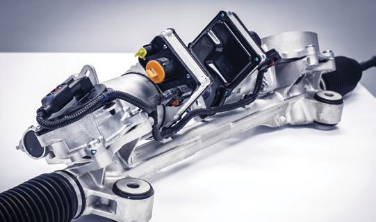
Steer-by-wire is no longer some distant concept-car talking point. It is already a production reality overseas and it is now properly on the doorstep of the Australian market.
Lexus Australia’s upgraded RZ range arrives in May, with the RZ 550e F Sport introducing steer-by-wire locally, while Mercedes-Benz has confirmed its first production passenger car with steer-by-wire later in 2026.
For most independent workshops, that still makes this a prepare-now topic rather than an everyday alignment-bay reality. But that timing can be deceptive in the technological pace of this new world – you can probably remember when power windows were considered an option and now here we are with basically every modern vehicle becoming an extension of your smartphone and having autonomous advanced driverassist system (ADAS) features.
The important point is it changes what steering actually is. What we currently see every day, an electric power-assisted steering vehicle, is a system where the electronics assist a mechanical truth. The steering wheel, column and rack still maintain a fixed relationship.
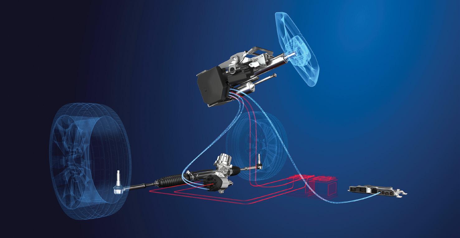
In a true steer-by-wire system, that mechanical truth is gone. The driver’s input is measured at the handwheel side, sent electronically to a front axle actuator and the steering feel fed back to the driver is generated by software and electric motors rather than simply transmitted up a column.
ZF’s own steer-by-wire descriptions are useful here because they strip the idea back to basics – the hand-wheel actuator measures the driver’s input and generates haptic feedback, while the front axle actuator positions the road wheels, all without a mechanical link between them.
Once the wheel is no longer mechanically telling the truth, the truth has to be agreed on somewhere else. That agreement now lives in software, sensor correlation, actuator position, power-supply stability, network integrity and calibration.
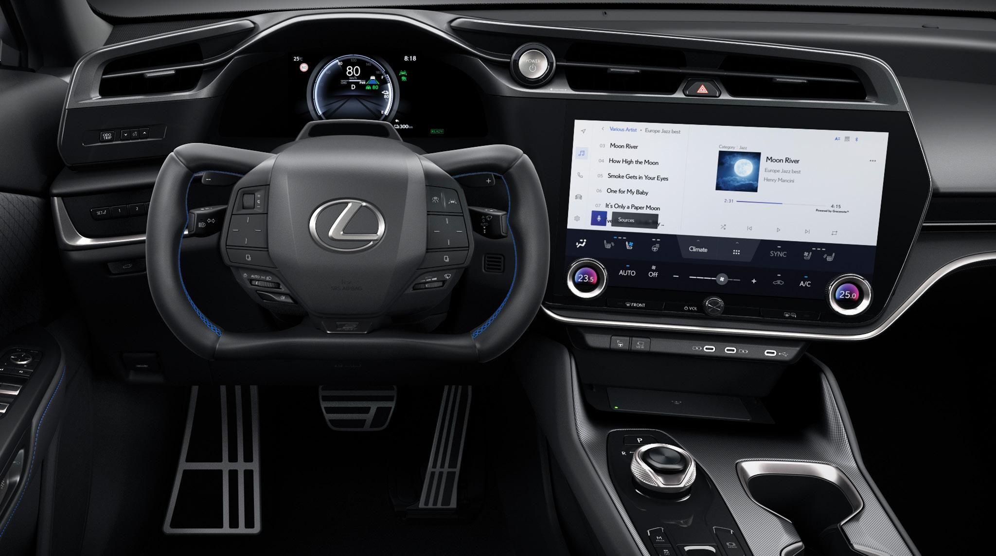
So the first lesson for workshop readers is this – steer-by-wire is not just electric power steering (EPS) with the column missing. It is a software-defined mechatronic safety system.
Why manufacturers want it
Manufacturers are not chasing steer-by-wire just to fit a cool yoke steering wheel. They want it because it solves several problems at once. It allows variable steering ratio without the old mechanical compromises. It helps isolate kickback and unwanted vibration.
A current real motto in the engineering world is ‘saving one gram, per engineer, per day’. This system gives more freedom in cabin and platform design because there is no intermediate shaft to route through the firewall.
It also interacts easier with electronic chassis control and fits naturally with the push towards higher levels of driver assistance – I’m sure more than one reader here would have already taken a ride in a driverless taxi while overseas.
What is good for engineer often means extra complexity for the repairer. The same lack of intermediate shaft that frees up packaging
also removes a mechanical reference point. The software-defined ratio that improves low-speed manoeuvrability also means ‘normal steering feel’ becomes a calibration issue, not just a geometry issue. The integration with stability control and ADAS means a steering fault is no longer guaranteed to stay in the steering system.
What actually changes in the hardware
For the technician, the easiest way to picture steer-by-wire is to split the system into two ends. At the driver end sits the hand-wheel actuator. That unit measures steering input through multiple redundant sensors and generates torque feedback through its own motor – yes, just like that Xbox steering wheel you play with.
At the road-wheel end sits the front axle actuator, which physically turns the steering gear. In between sits the control logic that constantly checks whether the driver request, vehicle motion and road-wheel position all make sense together.
This is where the workshop mindset needs to shift. In a conventional modern EPS
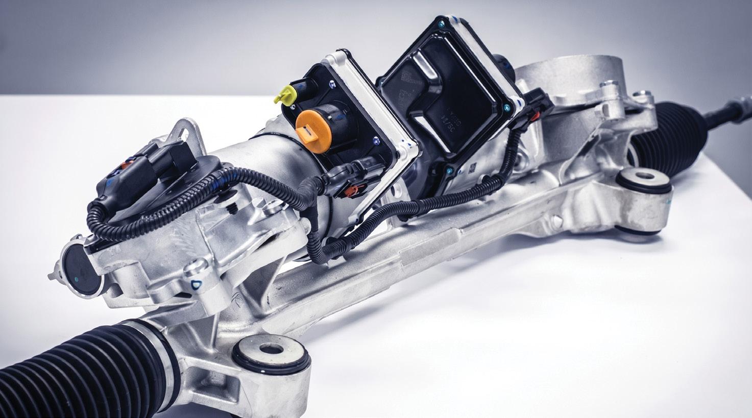
set-up, you still think in terms of column torque sensor, rack motor, steering-angle sensor (SAS) and mechanical centring. In steer-by-wire, some familiar ideas remain but their form changes. Steering feel is now synthetic. End-stops can be softwaremanaged. Straight ahead becomes a stored relationship, not just a physical alignment between wheel and rack.
That means a customer complaint of ‘it feels odd’ will encompass much more than just throwing it on the four-poster for an alignment.
Why diagnosis gets trickier
The first trap will be assuming every steering complaint still starts mechanical. It may. A bent component is still a bent component. Mechanical fundamentals do not disappear. But the way the vehicle presents the problem to the driver can change dramatically.
Imagine increased mechanical resistance at the road wheel. On a conventional system, that is usually felt fairly honestly through the steering wheel. On a steer-by-wire system, the front axle actuator sees the extra load, the controller interprets it and the handwheel actuator may feed back extra steering effort accordingly.
So a binding front strut top is not what we would be used to feeling it as – it is now an odd synthetic steering feel, a software representation of the problem.
Low voltage obviously becomes more serious but that’s nothing new – it’s getting hard to list any vehicle system that isn’t all reliant on a constant, steady diet of clean voltage.
Mercedes-Benz has already made it clear that redundancy is central to these systems, with two signal paths, redundant data and power supply and effectively twice the actuators needed to maintain steering capability. If one path becomes implausible, the car can keep steering using the remaining valid channels rather than simply going ‘manual’ like a conventional EPS without assist.
Mercedes also states that in an extreme failure, some steering control can still be supported via targeted individual-corner braking.
If there is one area where independent workshops are most likely to get caught, even while vehicles are near new and within warranty, it is wheel alignment. Traditional
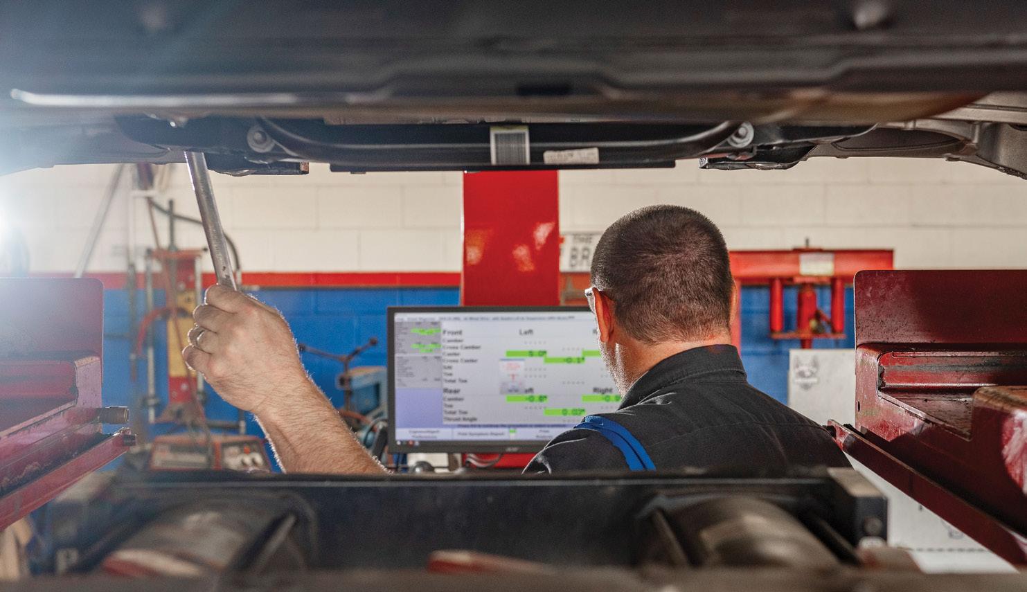
alignment logic starts to break down when the steering wheel is no longer the thing physically holding the front wheels straight. On a steer-by-wire vehicle, you can no longer assume that a level wheel equals a centred actuator. Straight ahead becomes three separate ideas that must agree. There is the driver’s visual centre at the hand wheel. There is the actual road-wheel position relative to thrust line. Then there is the electronic centre stored by the controller and cross-checked against yaw and lateral motion.
That means the alignment process becomes more scan-tool dependent. You may need the vehicle in a specific ride height or service mode. You may need to clear stored offsets, zero the hand-wheel side, command the road-wheel actuator to centre and hold, carry out the mechanical adjustment, then run post-adjustment learning and validation.
What this means for the Australian independent workshop
For now, Australian independents should still be in the research and preparation phase. The good news is the skills required are not completely foreign.
Good workshops already understand the value of power-supply quality, scan data, calibration routines and post-repair validation. The same discipline that separates a proper modern alignment from a quick toe-and-go will separate a steerby-wire-ready workshop from one that gets caught out.
The bigger change is mindset. Steering is no longer just a mechanical subsystem with electronics attached. It is becoming part of the software-defined vehicle. That means steering-component replacement will increasingly involve secure gateway access, coding and programming. It means collision and front-end repair will carry greater liability. It means a steering complaint that feels strange may be as much about data integrity as it is about hardware.
While true steer-by-wire will only be running around Australian roads on a handful of models this year and is not yet common everyday bay work, it is close enough and important enough that it deserves your attention now.
The first vehicle that catches a local workshop likely won’t arrive with a failed actuator at all and possibly not even a fault code. It may come in after suspension work, after a flat battery, after front-end repair or after an alignment that looked right but left the software behind.

Clinton Brett
The diesel engine has long been claimed as one of the most economical engine types. Unfortunately, with stringent emissions laws, rising fuel prices and changing diesel-owner demographics, service costs have increased and no longer meet some driver’s expectations.
Since starting Diesel Help Australia 13 years ago, my time dealing directly with diesel owners has been greatly reduced. But that is not to say I do not know how they operate. I am an observer, a people watcher, particularly of diesel owners. These observations, combined with thousands of diesel diagnostics over my career, have led to an obsession with diesel and the individual human perception of this beloved, fuel-efficient, high-towing-capacity vehicle that is now becoming a costly purchase.
But what if you could reduce the cost for your customers simply by educating them on the correct treatment of their diesel vehicle, how to drive it and a personalised service schedule?
What started as a personal tool to assist with creating hundreds of technical bulletins and training modules has become a tool I use daily to reduce diagnostic time for members. I have established several trends that can also be a helpful guide for your diesel-owner customers.
Based on several stereotypes of diesel owners and drivers, I created the Diesel Driver Profile or DDP. Most manufacturers have two types of servicing – normal and severe. I believe there is a need to provide owners with more service options to assist with budgeting and how long they want to own the car.
Witnessing certain failures, faults and worn components, I have linked them to:
• Driving style
• Distance and time travelled
• Family status
• Employment status
• Social network
• Hobbies
• Destination
• Location
• Temperature
• Altitude
• Type of holidays or recreation
• Gender
• Unique habits
I’ll share an extreme case recently provided by one of our members. Without knowing exactly how their diesel ute was used, based on the evidence provided I nominated the owner as Bunnings Greenthumb – weekend use only, average 20km distance, rarely exceeding 60km/h.
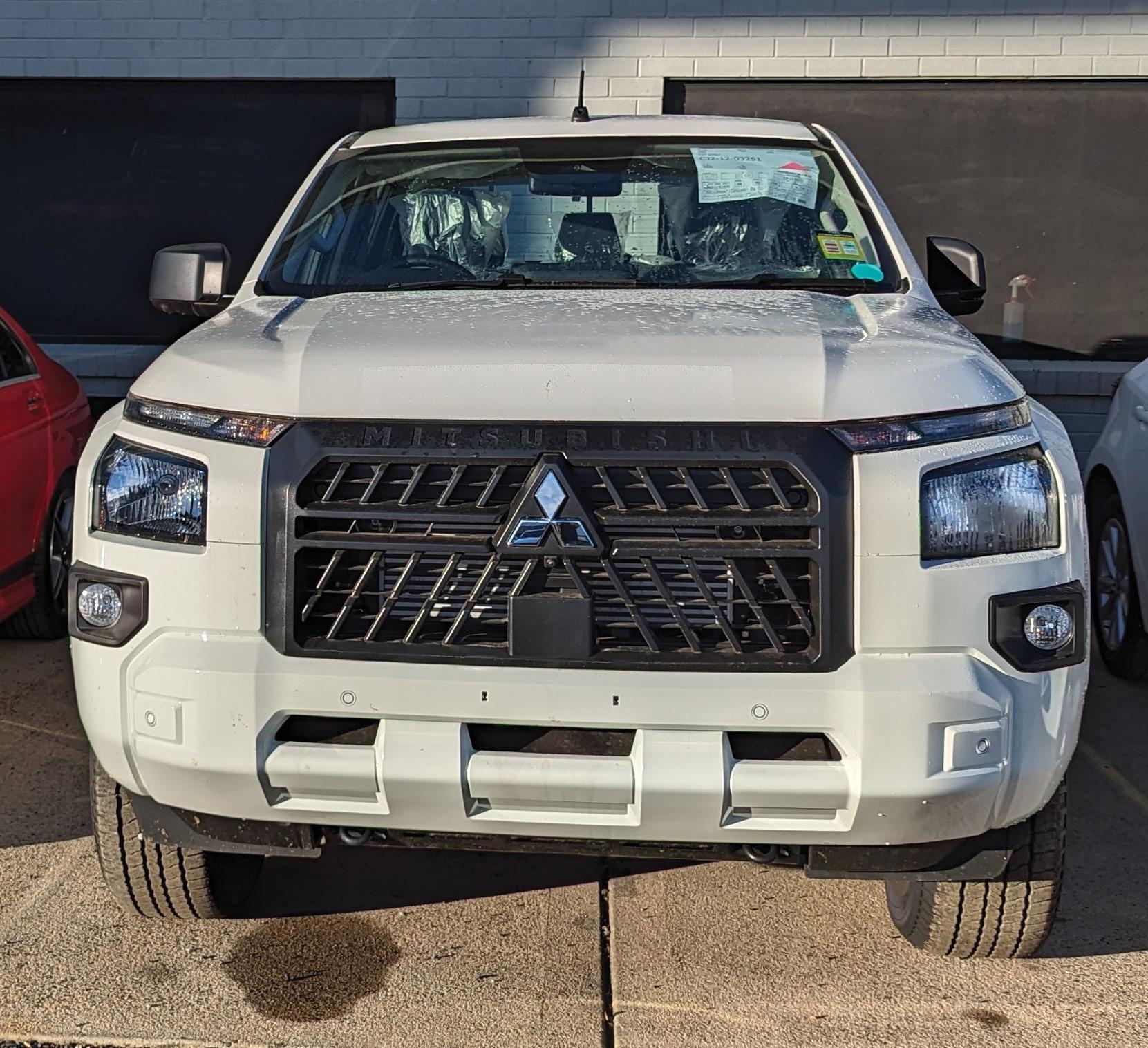
Vehicle: 2025 Mitsubishi Triton
Odometer reading: 300km
Location: Ballarat, Victoria. Annual daily temperatures average around a maximum of 17.5°C and a minimum of 7.1°C. Elevation is around 435m above sea level. The vehicle was reported to have been used for one year since being purchased brand new and involved stop-start idling in and out of the driveway, with the occasional short trip to nearby shops.
This is what I consider inappropriate diesel engine use – extended idling, short trips and no load being put on the vehicle. A misfire became evident and the owner booked the vehicle into the dealership
expecting the new-car warranty to cover it. As soon as the dealer workshop established the operating conditions, the claim was rejected on the basis that the car had been operated inappropriately.
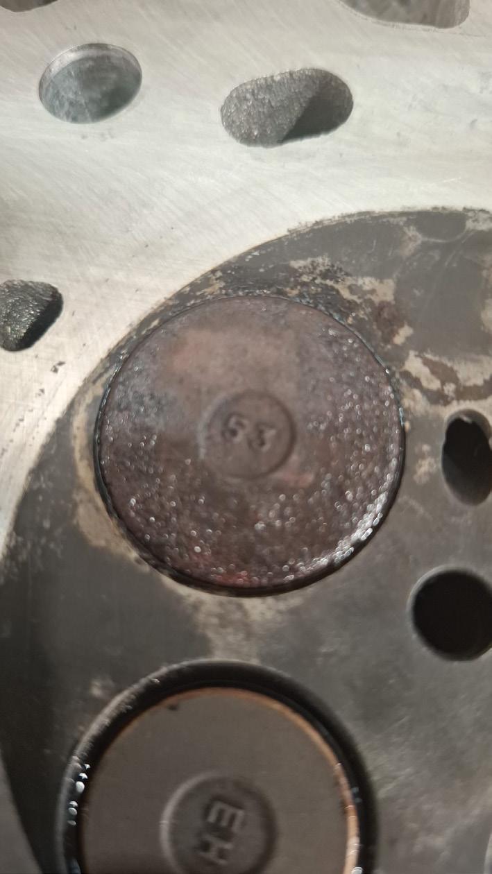
As a diesel fuel-injection specialist for more than 30 years, it is not uncommon to witness this. What I describe as cold corrosion is the result of poor combustion conditions that leave diesel residue on engine components.

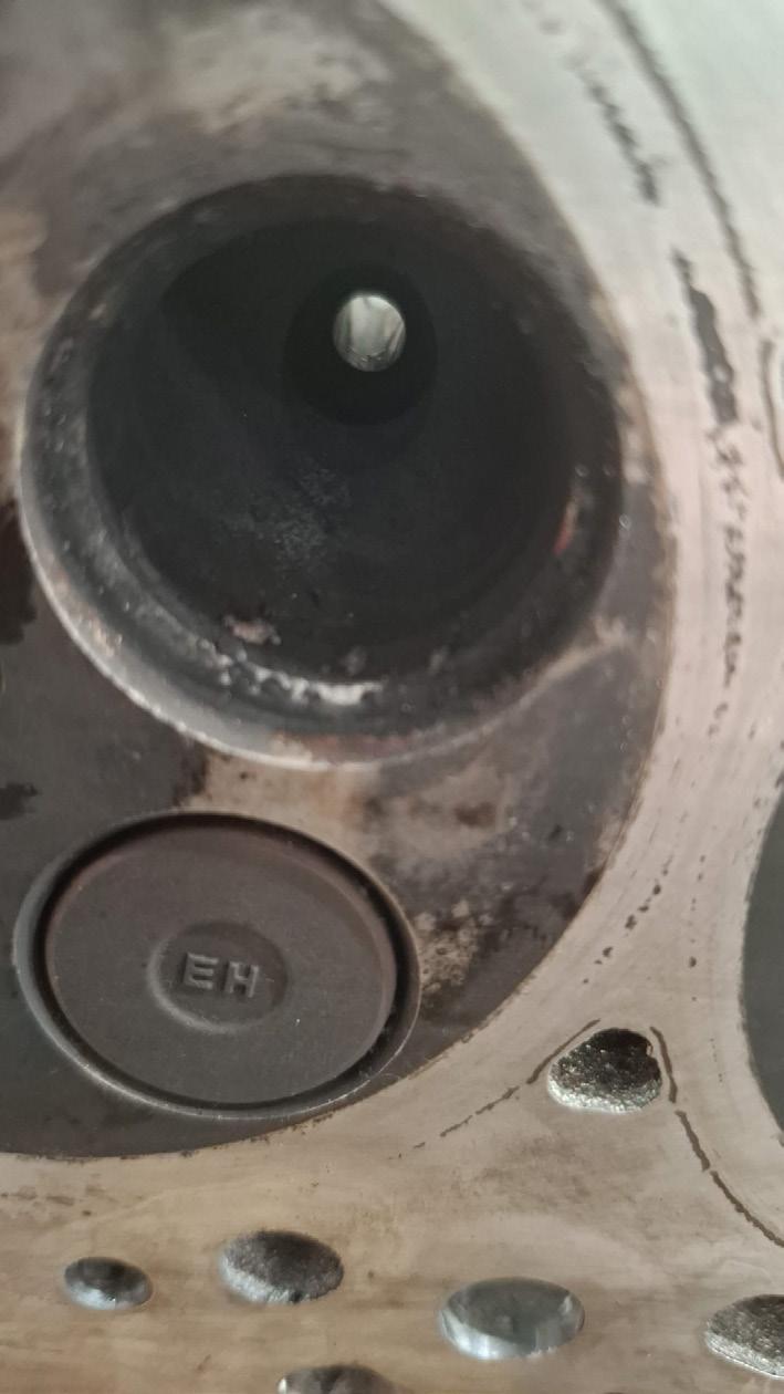
It can be highly damaging when the engine conditions required for proper combustion are not met, like putting hydrochloric acid in the engine. It is too cold, too often. Diesel is a thermal combustion engine, meaning an effective and efficient burn takes place with increased temperatures. When the engine is rarely operated under load, rather than burning cleanly and exiting through the exhaust, atomised fuel can remain in the cylinder as a liquid on vital metal components. Overnight, temperatures drop and the damage process accelerates.
Unfortunately, there is no service advice you could provide to this type of customer. I would only advise reconsidering diesel ownership and looking at a plug-in hybrid electric vehicle (PHEV) instead. A diesel is not the right choice for this style of use. Outcome of this case: The engine was replaced at the dealership at the customer’s expense.
As hybrid passenger vehicles become more common in Australian workshops, transmission servicing needs a little more discipline than a conventional oil change. The basic operation may look familiar but the system around it is not. Fill temperature and fluid specification both matter more than ever.
The oil change follows the normal workshop sequence – drain the oil, inspect its condition, check the transmission-pan magnet for wear material, replace the filter where applicable, then refill with the specified fluid. During refilling, maintaining the correct transmission-oil temperature is critical to
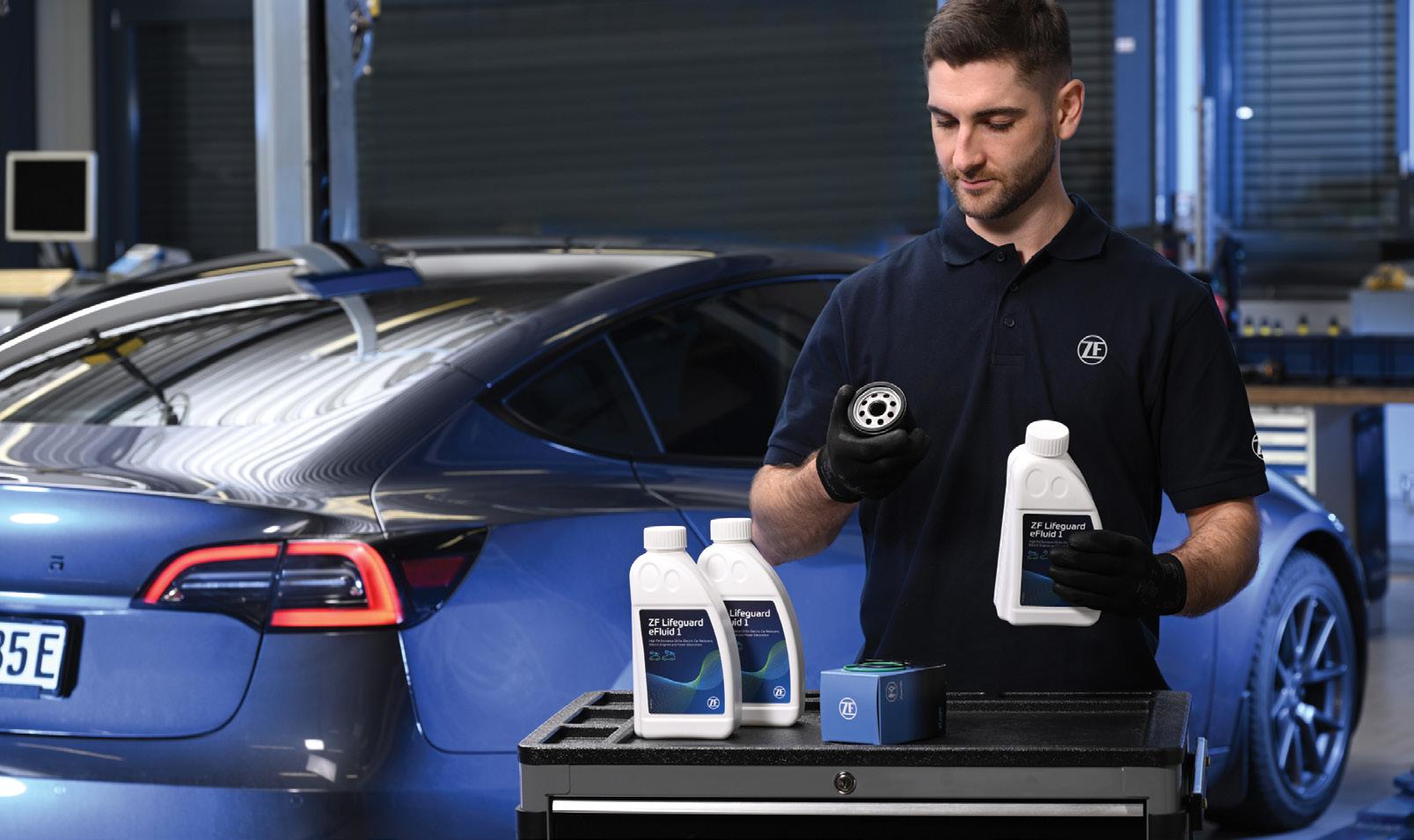
setting the precise fluid level. Because hybrid and electric-driveline systems generate torque instantly and operate under high thermal loads, fluid condition and fill accuracy play an important role in transmission durability and efficiency.
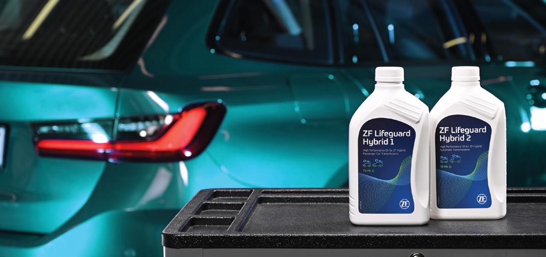
Hybrid and electric-vehicle (EV) transmission fluids also have different demands from conventional automatic transmission fluids (ATFs). They still need to lubricate and cool but they must also provide suitable electrical insulation, material compatibility and thermal stability around sensitive components.
ZF Aftermarket’s Lifeguard E-Fluids range has been developed for these hybrid and electric-driveline requirements.
Lifeguard E-Fluids are designed to work with copper coils and polymer materials inside electrified transmissions, supporting effective cooling of the electric motor and helping maintain driveline efficiency. The range covers a growing list of applications from manufacturers including Audi, BMW, Nissan, Polestar, Tesla, Toyota and Volkswagen.
For workshops, the message is straightforward – use the correct fluid, set the level at the specified temperature and treat hybrid transmission servicing as a controlled procedure, not just a drain and fill.
• Find out more at zf.com/au
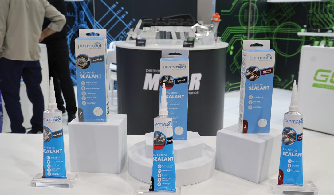
While Permaseal and Goss share historical roots in gasket production, both companies have evolved into distinct, specialised and respected brands for professional workshops and home garages.
For the first time, brand steward AA Gaskets (AAG) showcased both brands with new, innovative and technician-focused products at this year’s Australian Auto Aftermarket Expo (AAAE).
‘AAG’s distribution network provides our brands with extensive reach across the Australasian aftermarket, with AAG being able to leverage the full capabilities of an expanded and integrated product development team,’ said AAG General Manager Carl Wels. ‘We’re excited to explore new products, channels to market and future vehicle technologies, including chemical sealants, turbochargers, engine covers and tooling – nearly everything on display this year was a new initiative.’
Oil contamination and starvation are some of the leading causes of premature turbocharger failure. The oil-feed line is an often-overlooked service item when replacing a turbocharger but critical in ensuring it is lubricated, cooled and efficient.
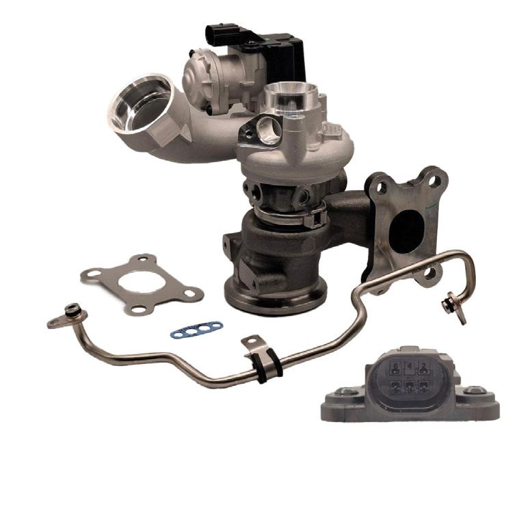
Goss’s new Petrol Turbocharger Kits are designed to combat this issue.
In addition to an OE-quality oil-feed line, Goss Petrol Turbocharger Kits come standard with a wastegate actuator, gaskets and the necessary hardware for a complete and seamless installation.
All Goss Petrol Turbochargers are 100 per cent balance-tested and
guaranteed for performance, quality and reliability. They cover popular vehicles on Australian roads, making Goss an ideal supplier for your next turbo replacement.
Find out more at goss.com.au
Permaseal was priming its public announcement of its new Chemical Sealing Program for weeks leading up to AAAE The range features three application products – sump, housing and manifold/exhaust. Each reflecting common workshop-use cases, these products forego the complicated colour-coordinated labels that confuse even the best mechanics.
With a curing time as quick as 60 minutes, these highperformances sealants are formulated to ensure customers get back on the road sooner.
Find out more at permaseal.co


Frank Massey
Agreat deal is being discussed about logic process when addressing diagnostic challenges.
This is, of course, built on experience, systems knowledge and reliable data. I do not subscribe to silver bullets. However, experience provides other assets that support a focused progression – intuition, for example.
With this in mind, I’d like to discuss the subject of fuelling evaluation using a scope, a subject that was brought up by delegates during one of my presentations in Australia.
To fully appreciate how this process developed over time, we need to go back to pre-catalyst days and four-gas analysers. Fault codes were non-existent or so basic that, in my opinion, the gas analyser could be considered a first-look tool, followed by a vacuum gauge, which is still a permanent member of my tool inventory.
So let’s explore these two tools, accepting they have little or no advantage if the engine will not run. The four gases we focus on are the carbon monoxide (CO) percentage, representing air/fuel ratio; hydrocarbons (HC) in parts per million (ppm), representing the percentage of incomplete combustion; oxygen (O2) percentage, representing the amount of O2 remaining following combustion; and carbon dioxide (CO2), representing the percentage of complete combustion and therefore an efficiency ratio.
The two gases that confirm optimum combustion efficiency are CO and O2. If these values balance at 0.5 per cent each, you will see HC at its lowest value and CO2 at its highest value, confirming a lambda 1 condition.
Simplifying matters, three plausible causes of combustion inefficiency are mechanical condition, ignition and fuel distribution. My first concern is mechanical efficiency as it represents the biggest cost/ value component in the repair mix.
The vacuum gauge, used correctly and with experienced evaluation, will expose internal cylinder-pressure problems. I am mindful of electronic compression and exhaust-gas-pressure scope evaluation, which I use and fully support, however this is tempered by the fact you can confirm internal mechanical faults with a vacuum gauge, avoiding the extra time and cost of using a scope.
This isn’t a contradiction on my part. Once an internal fault is identified – and as a professionally trained engine builder – I’m going to discuss the upcoming cost/value ratio with the customer prior to strip-down and thorough visual assessment.
I almost forgot – remove the plugs for in-cylinder combustion assessment. Plug service life has been extended far too long, in my opinion.
So along came the catalytic converter and it was out with the gas analyser and in with the lambda sensor.
This sensor, in all its various guises, reports the value of residual O2 in the exhaust stream. It has the advantage over the gas analyser in that it affords monitoring while driving the vehicle over a range of speed/ load conditions. It must, however, not be considered in isolation. The powertrain control module (PCM) will not be able to control correct fuelling with other critical sensor-input errors or other contributory mechanical factors.
Here’s a synopsis of correct fuel distribution and correct combustion control within a mechanically efficient engine, simplified for the purpose of a strategic plan of investigation:
• A sufficient fuel tank reserve, free from contamination. A lowpressure supply pump with correct flow, no cavitation and correct pressure and current draw. All injectors balanced for open-
pintle flow, atomisation, inductance and correctly coded where necessary.
• An ignition system providing sufficient energy, in joules, to the spark plugs, accurately torqued and ensuring correct electrode vector.
• An air-intake system with correct filtration, allowing minimal restriction, or pumping losses, of clean airflow through the manifold, which may have swirl or induction-path control. Accurately monitored mass or pressure within the system, free from leaks.
• Correct control and function of forced-air systems, either turbocharged or supercharged.
• A free-flow exhaust system and functional exhaust-gas recirculation (EGR) system, or dirty air. Remember, the reduction of air-mass calculation is based on the EGR open-duty ratio.
We need several reference points to determine if the PCM is correctly controlling fuel supply. Today we have the luxury of extensive correction data. It can, however, be confirmed with a four-channel scope.
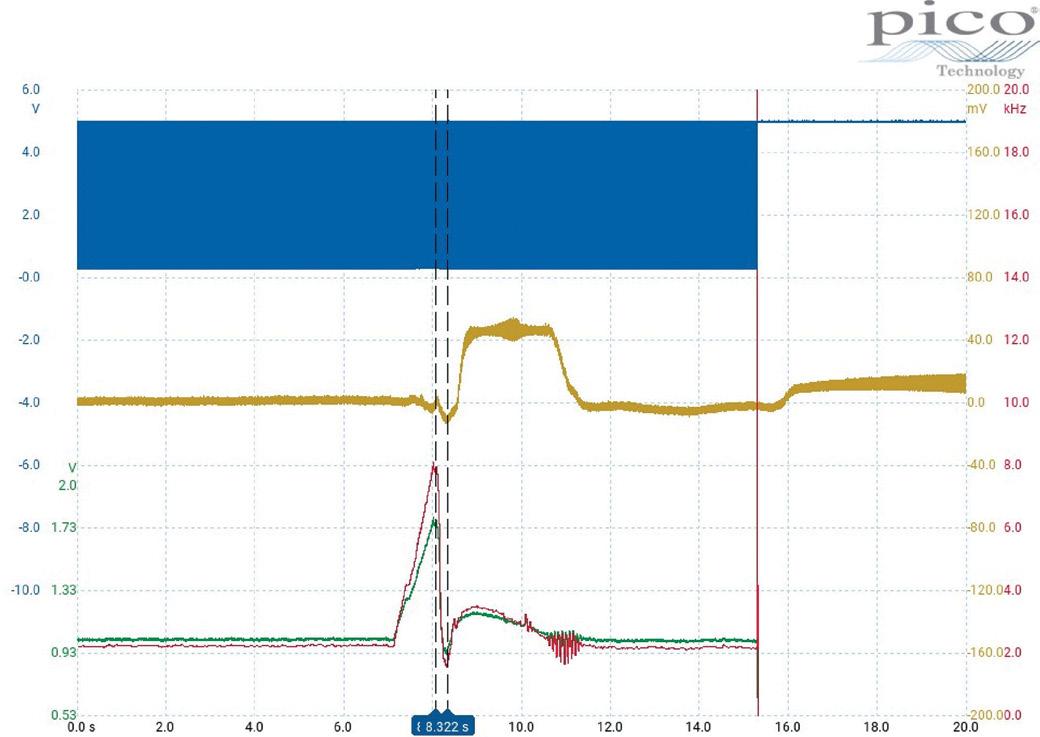
Set a base parameter on accelerator pedal position (APP) output over a 50-second sweep time and select the appropriate track. Choose air mass meter (AMM) or manifold absolute pressure (MAP) –or both if available – as your next channel.
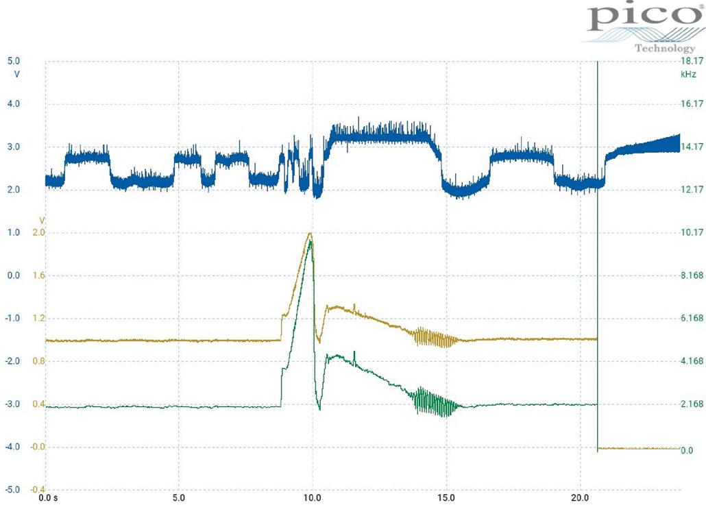
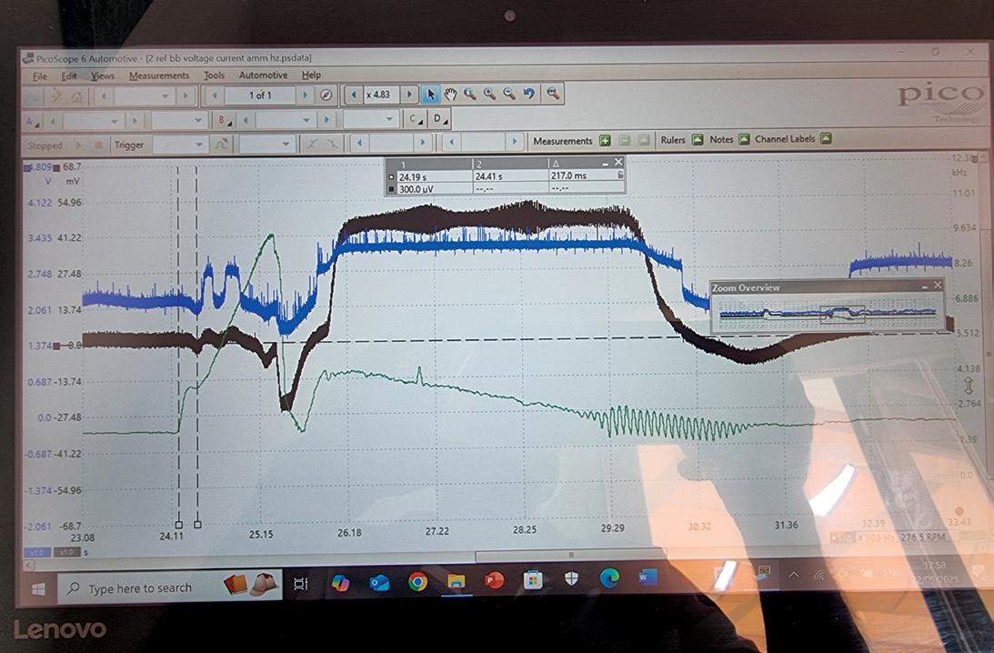
Select the O2-sensor output, which may be voltage, frequency or current.
Use the remaining channel, if available, for dual-channel O2 sensors. I mention frequency as an option. For example, in our Pico image taken from a Volkswagen Golf R, where the nominal frequency is 2200 Hertz (Hz) at stable nominal idle and 9600Hz at open throttle. Current is an interesting option as my experience of AMM measurement found 170mA at full load, even with diesel variants. Air/ fuel O2 sensors can be assessed with voltage or current, in milliamps (mA), depending on the variant.
The assessment
Fully warm up the engine, allow it to idle for a minimum of five to 10 seconds, then snap open the throttle. Note what should be a symmetrical response from the APP sensor, AMM and MAP sensor. Now compare the O2 response. There should be an approximately 170 millisecond (ms) delay with a rich sensor output, or O2 deficiency. This should hold throughout the open-throttle period and then, upon
throttle close and fuel cut-off, the O2 should promptly reverse to a lean response, or O2 excess.
This method allows an accurate measurement of critical sensor input and the PCM control of fuelling, as well as the ability of the injectors to present the fuel into the cylinder in a prompt, efficient manner.
Frequency scaling is straightforward, as suggested, expecting 2200Hz to 9600Hz. However, note that with performance software there can be a substantial increase in peak frequency. Peak values of 10 kilohertz (kHz) and 200mA current can be seen.
The k2 current clamp attenuation is 10mV = 1mA, Bosch air/fuel sensor range is ± 5mA, so 40mV = 4mA. AMM current expects peak current of 170mA, so 1.73V = 173mA.
Why do I do this? PicoScope software has a greater voltage range than current ranges and it is quicker to use without changing probe input selection.
A quick reminder. Air/fuel sensor output is inverted with respect to zirconia, so negative voltage/current equals rich, or oxygen deficient.
I recall a technique from the past that helped to understand if the PCM was in closed loop, as well as predicting if the PCM was receiving in-range key sensor values. Injector open periods were a reliable measurable value, set against a stable fuel-supply pressure, say 2.2-4.0 bar.
Set against variable high pressure, say 50-200 bar, homogenous and stratified fuel strategy and frequency/duty variation – notwithstanding direct and port dual-injection – today we must rely on correction values as a prequel to pending or confirmed diagnostic errors.

Iperformeda tap, bend and wiggle test on the body control module (BCM) and all surrounding wiring and found no faults.
However, when I touched the circuit at C10 as a test, using a grounded test light, the waveform on the scope faulted and so did the indicators. This was useful as it told me I was on the right track.
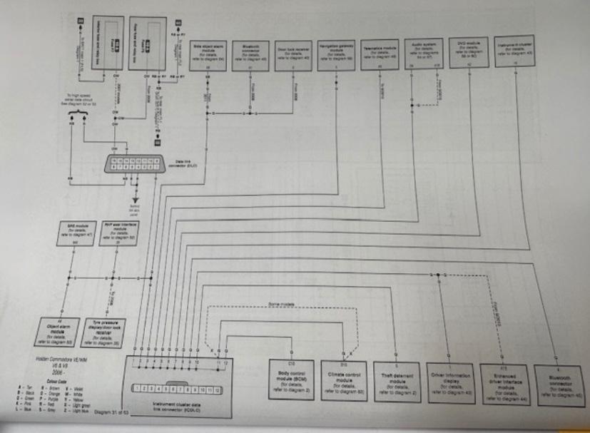
Looking at the wiring diagram I was using at the time, this vehicle had up to 18 modules connected to the local interconnect network (LIN), or low-speed serial data communication network (pic 5).
For diagnostic purposes, I decided to cut the C10 wire near the BCM. This C10 green wire goes to what was called the instrument cluster data-link connector (ICDLC) on the wiring diagram, better known as a splice pack. Next, I removed the instrument cluster and discovered the wiring loom was rubbing on the bulkhead (pic 6). However, this was not the fault.
At the instrument cluster, I cut the pin 15
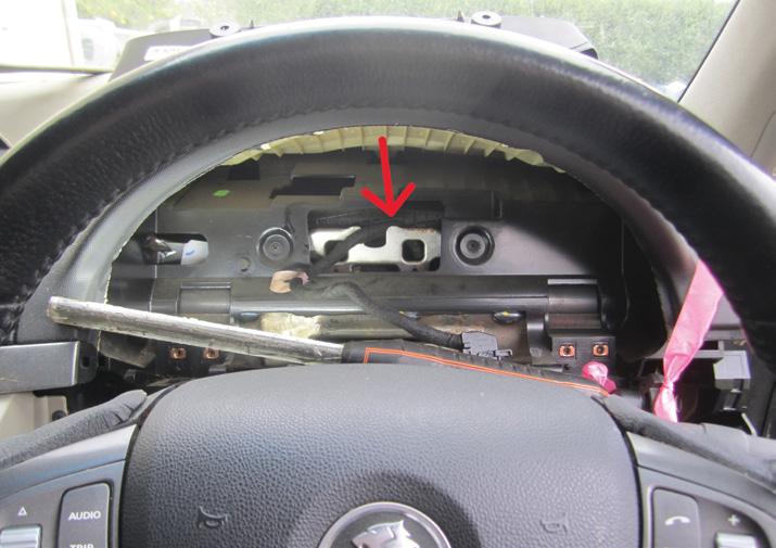
green wire to remove it from the LIN network, again for testing purposes. I connected a jump wire between pin 15 of the cluster and C10 of the BCM. In effect, this removed the rest of the modules on the network, allowing testing.
I started the car and bingo; the fault was not present. The scope had a nice, even pattern with no glitches (pic 7) and the indicators and dash worked properly with no faults. However, when I performed the grounded test-light test again the scope and indicators faulted. This confirmed one of the modules on the network was faulty, probably with a grounding issue. But which module?
Over the next few days, I tried unsuccessfully to find information or a diagram showing the correct location of the splice pack.
I knew the splice pack would be somewhere behind the dash. It’s where all the green LIN wires from all the modules connect into one location before going to terminal C10 of the BCM. Not being able to find it meant I’d have to locate all the modules on the network and, one by one, disconnect them and test the system, starting with the easiest to access. None of them were easy.
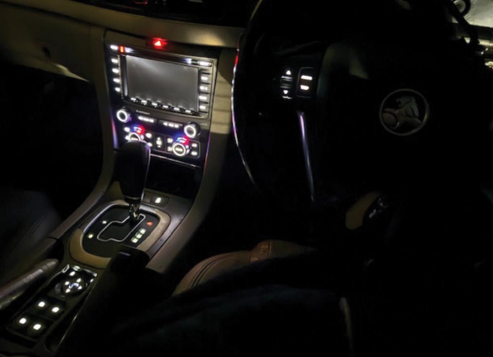
The car sat around for a few days and during this time I noticed the battery would sometimes go flat. One night I was walking past it and noticed most of the dash backlights illuminated but not the cluster (pic 8). The following morning the battery was flat. It all started to make a little sense. Remember, the car had arrived with two batteries, one completely flat. I called the owner and she commented, ‘I forgot to tell

you that when all the problems started with the dash, keys and indicators, the battery started going flat.’
Armed with this information, I again referred to the 63-page wiring diagrams for clues, once again with little luck, only knowing everything was interconnected.
A few days later I got back onto the car with a fully charged battery. I started locating and unplugging modules, from the easiest to access to the more difficult, starting with the right front-seat module. This was not the faulty module and neither were the audio module, climate-control module or sensing diagnostic module (SDM), otherwise known as the airbag module, located under the centre console.
Next came the entry module, located in the left-rear of the vehicle, which was difficult to get to because the rear seats were broken and would not fold forward. It was not the faulty module either.
During this journey of stripping out the car in search of the different modules, I discovered
another damaged wire near the battery with some copper exposed. This was a green low-speed serial data communication wire. Was this the problem? On closer inspection it was not, so I repaired it and moved on. By this point the interior of the car had been mostly stripped out, to the point where my wife walked past, looked inside and said to me, ‘Gee, it sucks to be you.’
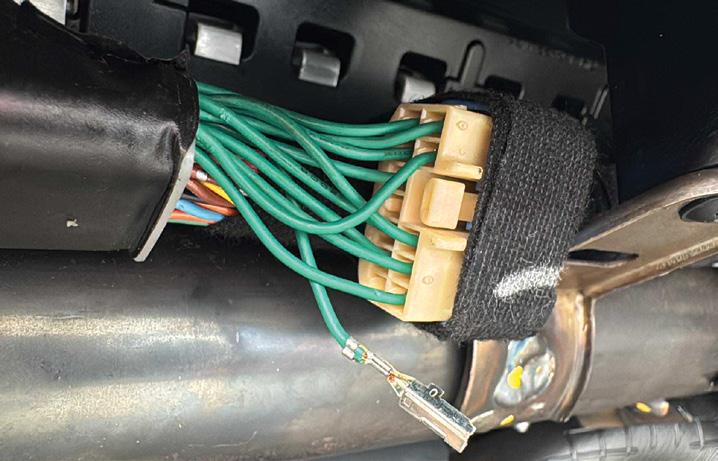
I really needed to find the splice pack and a few days later I finally found it at the left front behind the dash, attached to the intrusion bar that went across the vehicle. It’s a 12-pin connector with 11 green wires and no identifying marks, numbers or letters. I unplugged the connector and, using a multimeter with the car powered down, I went around all the pins looking for something abnormal and this really paid off. One of the pins had a kiloohm reading to ground, which could have well been the problem, so I depinned the suspect wire from the splice pack (pic 9), reconnected the splice pack, started the vehicle and the fault did not occur.
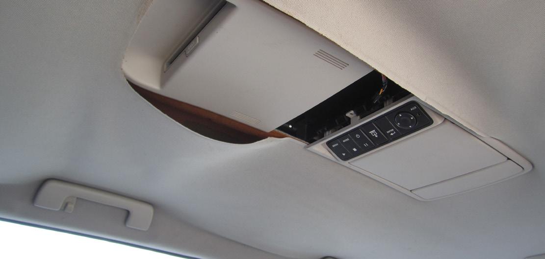
My joy was short-lived, however, as I needed to identify the wire and which module it was connected to. I knew I could probably identify a pattern with the wiring from the terminals of the modules I had already removed but that would be time consuming. Eventually, with the help of a colleague and a different manufacturer’s wiring diagram, I was able to identify the wire in question, which went to the DVD-player module mounted in the roof of the vehicle (pic 10 and 11).
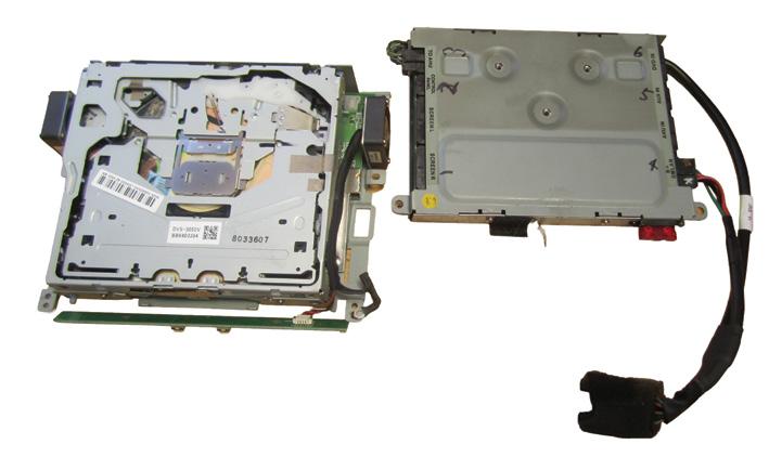
I removed the DVD player from the vehicle for closer inspection and to my annoyance, none of the wires were the green one connected to the splice pack. Another check of the wiring diagram confirmed I should have been looking for the DVD-player module, not the DVD player, a separate component. Go figure.
I didn’t want to go off half-cocked and I was having trouble identifying exactly where the DVD-player module was. The service information stated it was located in the roof and the roof lining would need to be removed to access it. I eventually did locate it in the roof, rearwards of the DVD player and yes, it was tucked up between the roof lining and the roof of the car.
Because I’d already removed the DVD player, I was able to place a torch up into the roof
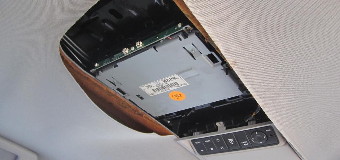
cavity. This pushed the roof lining down enough to allow me to get to one of the six wiring-harness connectors – the power and ground for the module – and unplug it.
A test of the wiring connector green wire confirmed the correct wire going to the splice pack and, with the connector unplugged, I had continuity with the splice-pack depinned wire and no grounding. With the module still installed, I checked the pin relating to the green wire and found it was grounding, confirming a short in the DVD-player module.
But wait, there’s more. Remember the parasitic drain from the dash backlights staying on – and having studied the wiring diagram – I knew this was all connected, so I did not want to leave the DVD module plugged in via the other five wiring connectors as the short in the module could cause the dash backlights to come on. With a great deal of contortion, I was able to remove the three mounting screws that held the DVD-player module in place. I was then able to slide it forward through the DVDplayer hole and remove the last five wiring connectors.
Next, I connected the scan tool and successfully cleared all DTCs logged in the systems. There were a lot because of the testing that had been performed with modules and components disconnected. Only two DTCs remained after this and they weren’t of particular concern as they’d been there from the start. I started the vehicle and communicated and analysed the data in all the systems. All seemed OK.
I carefully road-tested the vehicle with a lot of the interior still removed and all seemed fine without the DVD player and module installed (pic 12, DVD player left, module right). Over the next few days, I road-tested the vehicle several more times and observed no parasitic drain and correct operation of all accessories.
I then repaired the test wiring and refitted the interior, including the DVD screen and trims, while leaving no evidence the DVD player and module were missing from the car. Now to the key problem. As mentioned, I used key one during the diagnostic process because it was OE and known to be good and reliable – I did not want to be confused by any issue with the shopping-mall key the customer had sourced previously.
It’s worth mentioning I did notice two keys registered to the vehicle while observing the data in the immobiliser system with the scan tool. This told me that key three was a cloned key and it did not work properly anyway. It sometimes would not start the car and the remote would not lock or unlock the doors. To be honest, this didn’t surprise me because the customer had told me the supplier didn’t have any contact with the vehicle when she bought key three, which is required when, one, cloning a key for this vehicle and, two, programming the keylessentry system.
I’d previously checked the signals coming from key three and decided to start again with it. I generated a new transponder chip and then programmed it to the vehicle. Next, I programmed the keyless-entry remote to the vehicle using diagnostic equipment. With the key and remote now working properly, I retested the vehicle and all was now working fine.
This job really started out a mess. I was almost certain the fault was caused by the water inside the vehicle. I’d even discussed with the owner the possibility of writing the car off if water ingress was found to be causing the faults in the safety systems and if new parts to repair the car were unavailable. However, that did not turn out to be the case. In retrospect, there could be a case for thinking the mould contributing to the failure of the DVD module but I have no evidence of such.
What I do know is that with some patience, a co-operative owner, good diagnostic process, some good fundamental knowledge and skills – and the input of Rod Maher and Marty Hosie – it all culminated in a good outcome and satisfied owner.
Good luck plugging your scan tool into this car and it telling you exactly what’s wrong. Happy diagnosing.
The vehicle was not charging the 12V battery. There was a charging-system warning on the dash.
The owner’s regular mechanic referred the vehicle to us for diagnosis. Verified the customer complaint.
Started with the usual diagnostic checks, including a 12V battery test, chargingsystem checks and an all-lights test.
With the engine running, there was no charging voltage reaching the 12V battery, which is located under the bonnet.
Carried out a full vehicle electronic scan and several systems had low-voltagetype fault codes stored, including the electric powertrain/Integrated Motor Assist (IMA) code, P0AE1 – Bypass contactor malfunction
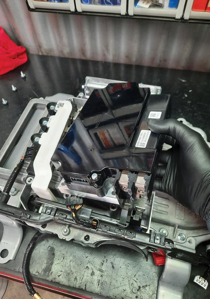

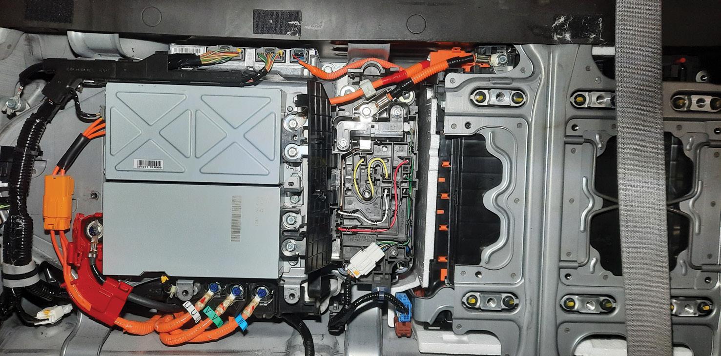
This code would clear but immediately return when the ignition was switched on. The vehicle would still start and run as this system still uses a traditional 12V starter motor but employs a DC-DC converter from the high-voltage system for 12V battery charging.
I obtained access to the Honda data portal and researched the code-setting criteria and testing procedures for the P0AE1 code.
The fault-setting criteria showed that if the inverter does not verify that the voltage on both sides of the bypass contactor matches within a small time frame of 210 milliseconds, it will not engage the main high-voltage (HV) contactor and will set the fault code.
After running through the testing and verifying that the HV contactors were not the cause, and after collaboration with some TaT Technical Team members, I decided to remove the DC-DC converter and benchtest it (pic 1 and 2).
Results showed the DC-DC converter was functioning correctly.
Visually inspected all connections and components for signs of failure.
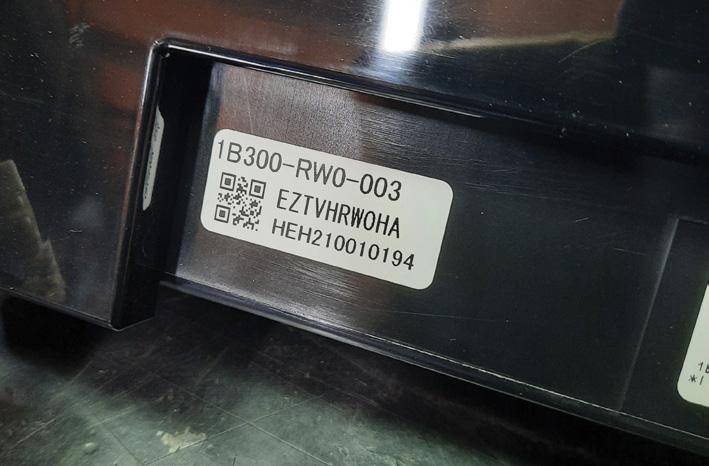
All testing led to the HV inverter as the cause of the fault (pic 3 and 4).
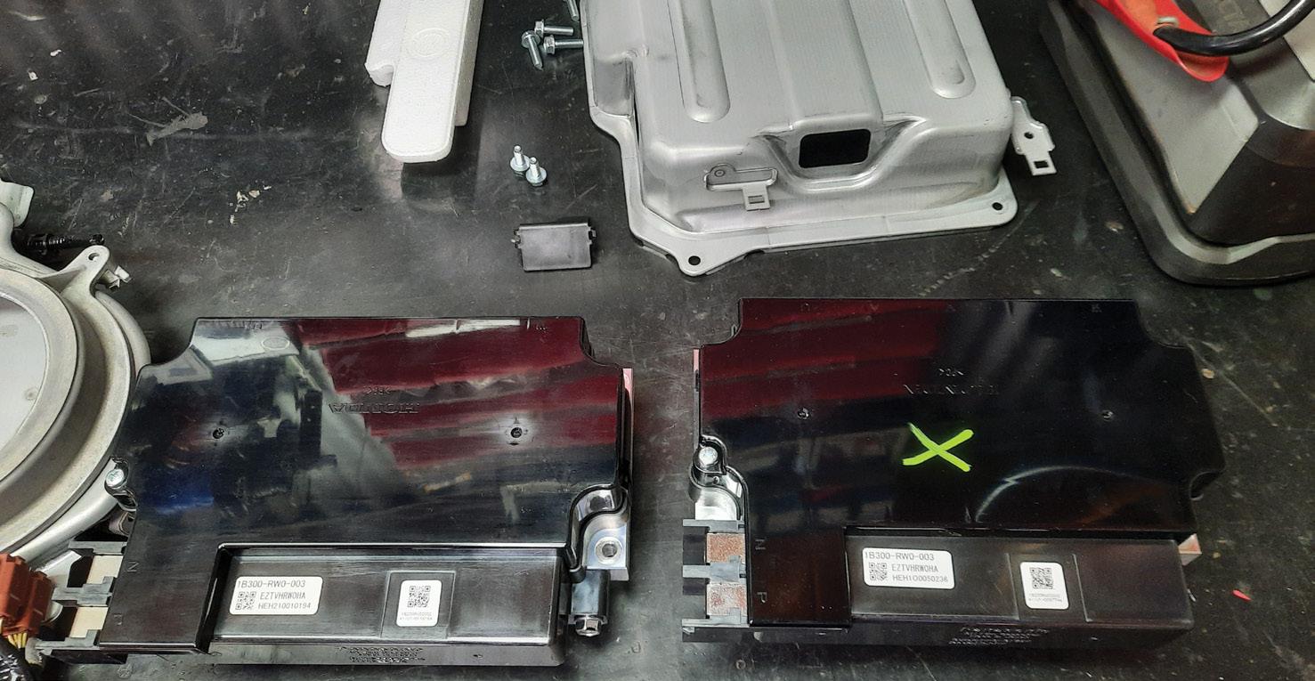
Fault description
Faulty HV inverter.
Removed and replaced the HV inverter with a used unit (part number 1B300-RW0-003).
Reassembled all components and retested the IMA system and 12V charging system. Road-tested the vehicle while monitoring live data to verify the repair and confirm correct operation (pic 5).
Recommended time
Diagnostic time was four hours, taking into account preparation and research. Repair time was three hours, taking into account the location of parts and carrying out the repair to a tested outcome.
Repair Solution by TaT Tech Team member Marty Hosie.
Customer complaint
The red battery-malfunction warning light was displayed on the dashboard.
Problem summary
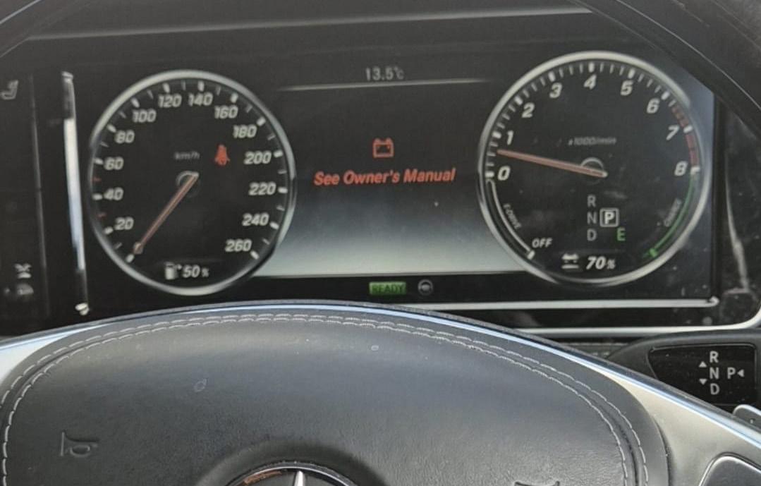
Confirmed the red battery-malfunction warning was active (pic 1).
During testing, the a/c did not operate correctly and after approximately five minutes the a/c compressor began to rattle loudly.
The vehicle otherwise started, ran and moved under petrol-engine power without issue.
Diagnostic sequence
Connected a scan tool and found the following relevant fault codes:
• P1CA100 – Isolation fault in the highvoltage on-board electrical system with open contactors
• P1CA300 – Isolation warning in the highvoltage on-board electrical system with open contactors
• P1CA400 – Isolation warning in the highvoltage on-board electrical system with closed contactors
• P1CB400 – Power supply for circuit 30c has a malfunction
• P0A0E00 – Interlock circuit of the highvoltage on-board electrical system has a sporadic malfunction.
The high-voltage (HV) isolation and interlockrelated faults indicated a possible issue with a component connected to the HV system. While the vehicle could run on the petrol engine, the hybrid system was in fault mode.
During operation, the a/c compressor –which is HV powered – began to rattle excessively.


Fault description
The a/c compressor (pic 3) had developed an internal fault, resulting in the HV isolation error.
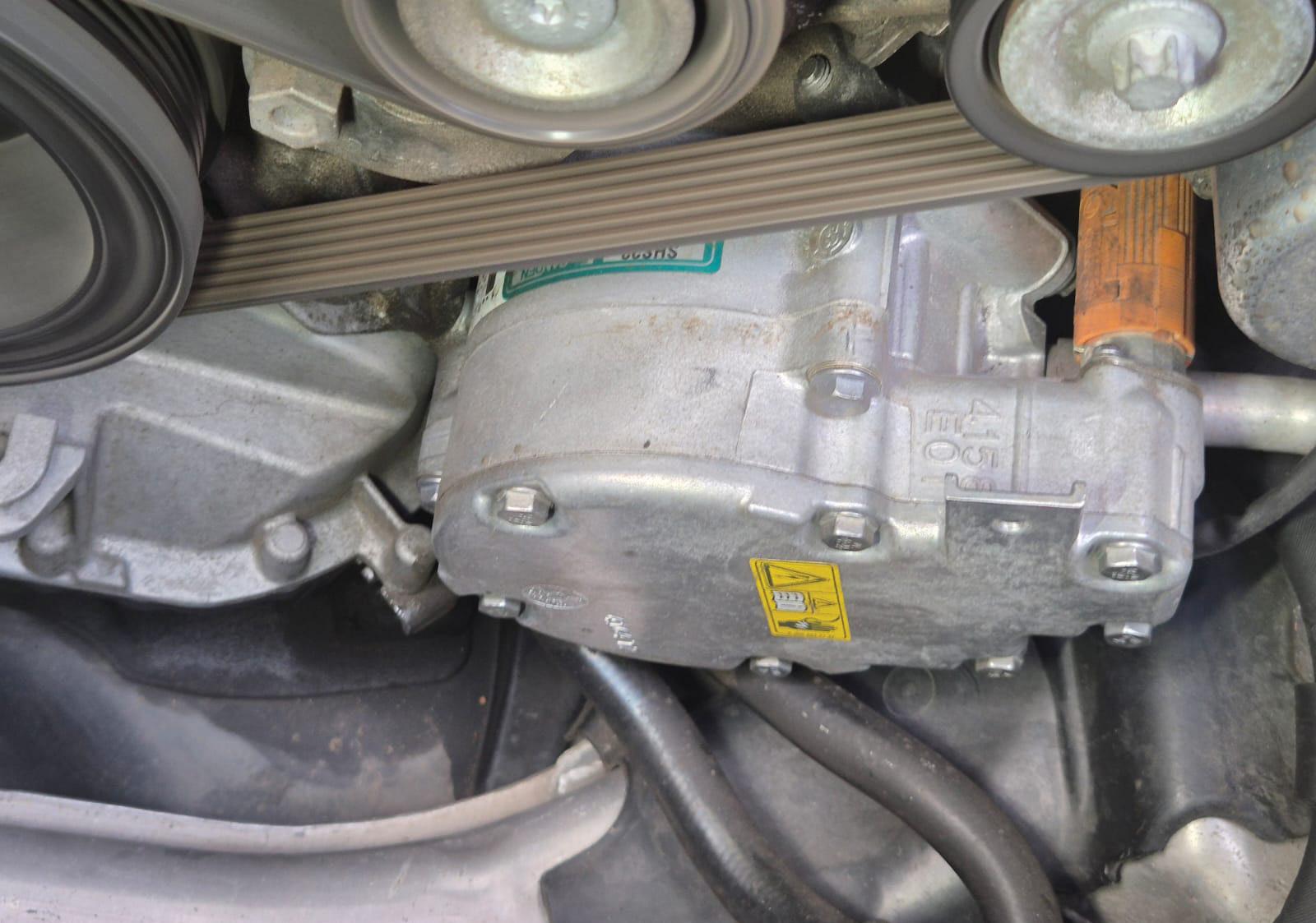
This fault had caused multiple HV system warnings and triggered the red batterymalfunction indicator on the dashboard.
Fault solution
Replaced the faulty a/c compressor, which was causing the isolation fault in the HV system.
Cleared the fault codes and confirmed the hybrid system operated normally, the malfunction warning was no longer displayed and the a/c functioned correctly.
Recommended time
Diagnostic time was 90 minutes, taking into account preparation and research. Repair was not carried out by the contributor, only the diagnosis.
Repair Solution by TaT Tech Team member George Anagnostoudis.
Customer complaint
The check-engine light (CEL) was on.
Problem summary
No driveability concerns were reported and no performance issues were evident on road test. However, the CEL would return after clearing faults.
The primary concern was an exhaust-gas recirculation (EGR) range/performance fault being set despite an aftermarket EGR valve having already been fitted.
Diagnostic sequence
A scan-tool check confirmed the P0404 –EGR range/performance fault returning after clearing and requiring more than one key cycle and road-test conditions to illuminate the CEL.
Carried out visual and functional checks out on the EGR system and intake system. The EGR valve had been replaced with an aftermarket unit and the vacuum supply routing had been swapped and verified. Inspected the intake manifold and EGR port for carbon build-up, with no excessive restriction found.
System operation checks were then focused on vacuum control as this engine uses multiple vacuum solenoids and a vacuum reservoir to control EGR flow and the throttle plate for EGR pressure differential and shutdown control.
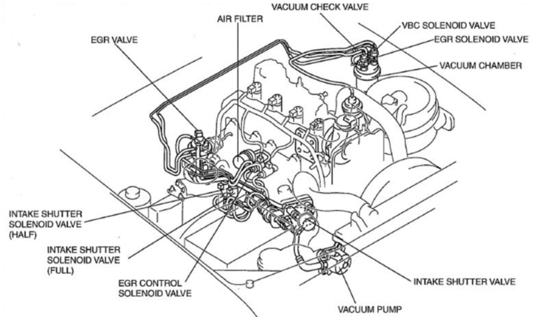
Reviewed reference vacuum routing and component layout to confirm expected solenoid functions and plumbing paths (pic 1).
Active tests confirmed mass air flow (MAF) readings changed when commanding the EGR vacuum solenoid, indicating the powertrain control module (PCM) could influence airflow via vacuum control.
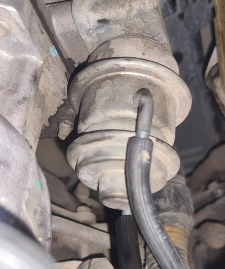
Swapped the duty-cycle vacuum solenoid on the strut tower (pic 2) with the boost-control

solenoid as a known interchangeable test and there was no change in fault behaviour.
Removed and bench-tested the on/off vacuum solenoids under the intake manifold, which confirmed audible actuation and vacuum direction change.
Checked the throttle vacuum actuator (pic 3) behaviour with a hand vacuum pump. One diaphragm would move the throttle plate partially, while full closure required vacuum applied to both chambers, aligning with a system that uses staged throttle closure depending on operating mode.
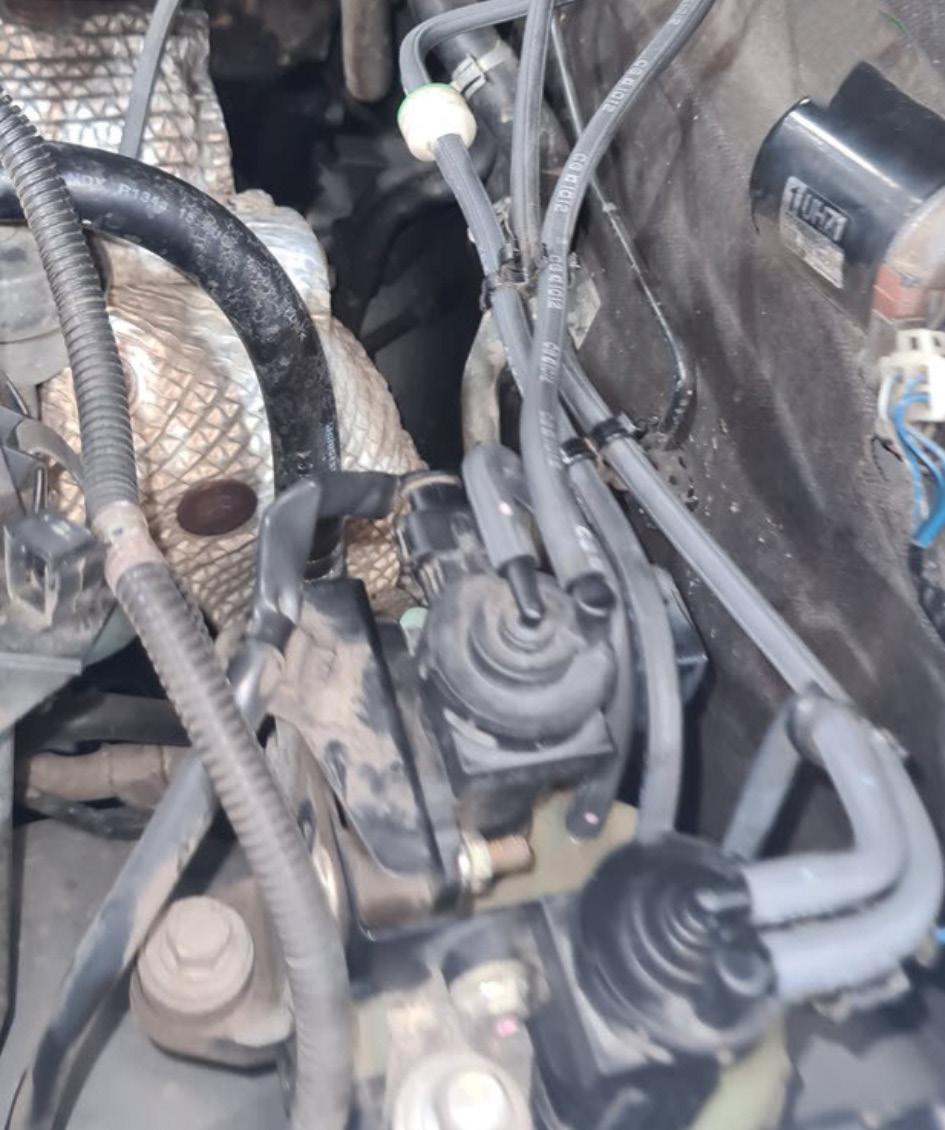
Next, checked the vacuum plumbing and reservoir feed and found the vacuum supply to the vacuum tank was insufficient. Further inspection identified the one-way check valve in the vacuum feed installed in the wrong direction, preventing the vacuum reservoir from being charged.
Corrected the check-valve orientation and the vacuum supply was restored (pic 4).
Cleared the fault codes and road-tested the vehicle over multiple drive cycles. No DTCs returned and the CEL remained off.
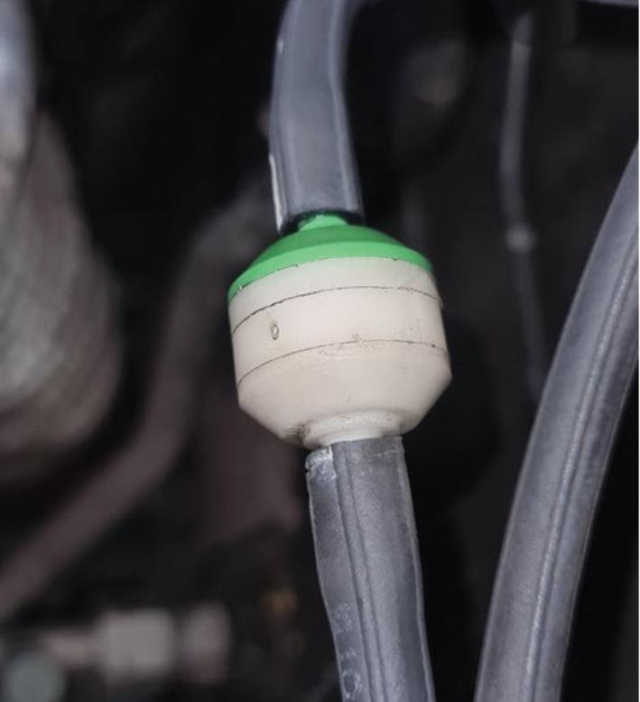
The vacuum system one-way check valve was incorrectly fitted, blocking vacuum supply to the vacuum reservoir.
With the reservoir unable to store and stabilise vacuum, the EGR and throttle vacuum control system could not reliably achieve the commanded positions, resulting in the PCM detecting an EGR range/ performance condition and setting P0404.
Reinstalled the vacuum one-way check valve in the correct flow direction to allow vacuum to charge the reservoir, then cleared DTCs and confirmed correct operation with an extended road test over multiple key cycles.
Recommended time
No diagnostic or repair time was supplied. Repair Solution by TaT Tech Team member Deyan Barrie.
The vehicle had a no-start issue, no remote function and multiple warning messages illuminated on the dash. It would start occasionally.
Problem summary
The vehicle was dropped off in a nonstart condition. It would intermittently start after repeated button presses and general manipulation, with numerous warning messages displayed on the dash.
Diagnostic sequence
A full vehicle scan revealed hundreds of stored fault codes, with multiple control units reporting no communication with the body control module/comfort control module (BCM/CCM).
This is a known issue on this platform, so inspected the rear corner of the boot area for water ingress.
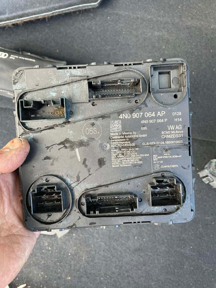
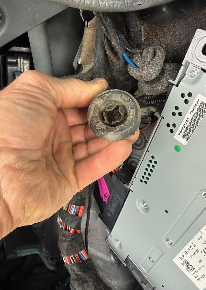
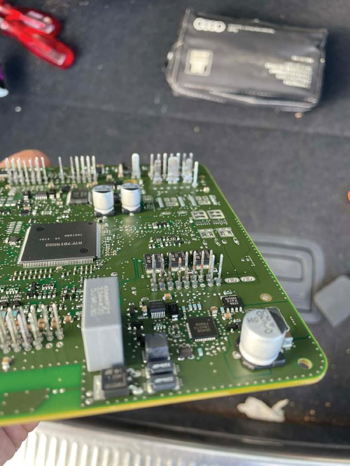
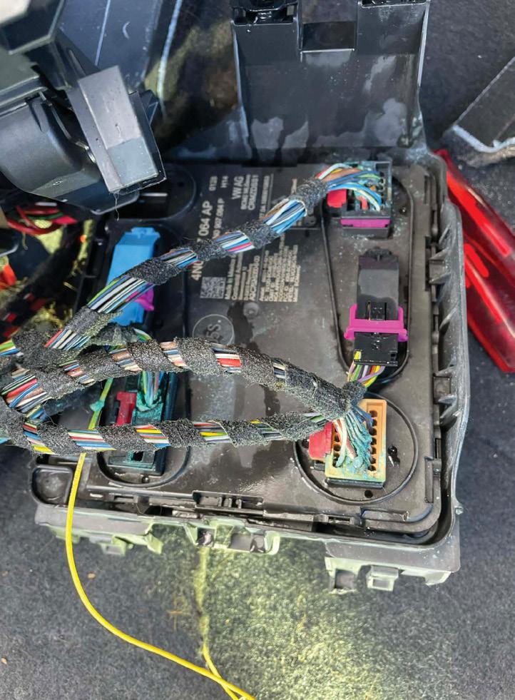
There was no obvious initial evidence of this but did find a pool of water once the side trims had been removed. The BCM/CCM was sitting in the water (pic 1, 2 and 3). Manipulating the module and wiring would occasionally allow the vehicle to start, confirming this area as the source of the fault.
Removed the CCM and found the connectors were heavily corroded.
Further inspection showed 15 to 20 wires had broken away from the pins due to corrosion.
Replaced the damaged pins as required, fitted a new CCM and cleaned the remaining terminals. These pins are available through Audi, although they are very expensive (pic 4).
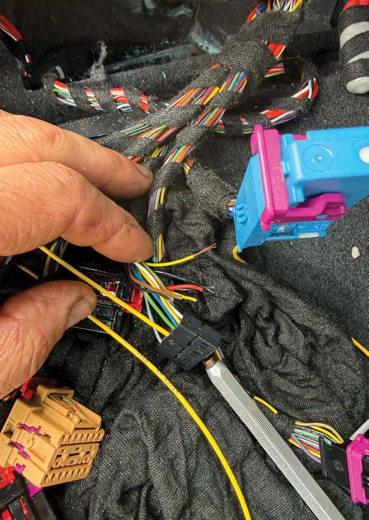

Programmed the new CCM using Offboard Diagnostic Information System (ODIS) and carried out all necessary resets.
Fault description
Blocked sunroof drains had allowed water to enter the cabin and soak the CCM, causing corrosion, wiring damage and widespread communication faults.
Fault solution
Cleared the blocked sunroof drains (pic 5), replaced the CCM and repaired or replaced the affected wiring harness terminals and wiring as required.
Diagnostic time was one hour, taking into account preparation and research.
Repair time was five hours, taking into account the location of parts and carrying out the repair to a tested outcome.
Pins can be difficult to source from the dealer but they are available. There are four different sizes, with different wire-thickness options.
Blocked sunroof drains are a common issue on these vehicles, so they are worth checking during routine servicing.
Repair Solution by TaT Tech Team member Carlton Quay.


As a beginner, would you initially purchase a basic digital storage oscilloscope (DSO) or choose a fully integrated, industry-standard DSO?
Following on from a very successful two-part webinar on The Why and How of Diagnosing CAN Bus – and based on the feedback received – there was clear excitement from participants wanting to further their knowledge, not only in purchasing and using an oscilloscope to diagnose controller area network (CAN) symptoms but in extending its use to diagnose a wider range of faults. While there were plenty of competent users amongst attendees, there were others looking to either upgrade or purchase a new oscilloscope to join in, along with those in need of an entry point. As a result, we’ve decided to walk the talk here. In this introductory article, we will begin by examining the pros and cons of choosing a basic, simple oscilloscope, based on your personal needs, and then use this as underpinning knowledge and a stepping stone to exploring the benefits of a fully dedicated, automotive industry-standard DSO with integrated settings.
But first, what is an oscilloscope and how does it differ from the faithful, well-worn digital multimeter (DMM)?
What is an oscilloscope?
Oscilloscopes have many advantages. However, the most striking is this:
• Unlike a DMM, which continuously displays changing numbers (pic 1, blue axis and DMM)…
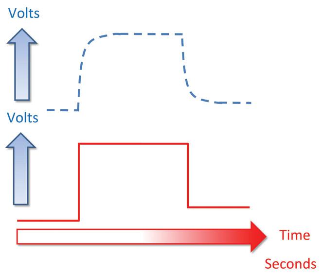
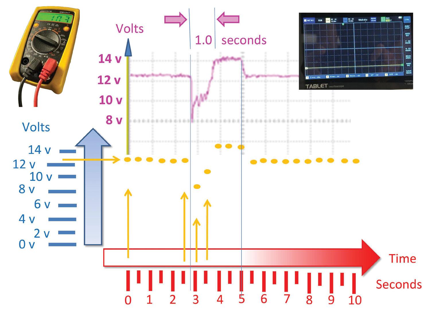
• An oscilloscope samples voltage at regular intervals and displays it over time as a series of dots. These dots are perceived by the eye as a continuous line (pic 1, yellow – more on this later in the text).
Hypothetical scenario: Measuring battery-cranking voltage
Let’s assume you wish to observe a suspect vehicle’s battery-supply voltage under heavy load such as during engine cranking, where current draw from the starter motor may range between 100A and 400A.
This is important because the battery’s ability to handle such loads is reflected in the voltage drop during cranking, hence the term cold cranking amps (CCA).
But how is the battery expected to behave and how does it actually behave during cranking and starting, voltage-wise?
After all, we are typically accustomed only to observing changing numbers when using a DMM.
Actual battery-voltage behaviour during engine cranking
Referring to the waveform trace (pic 1, purple):
• At approximately 2.5 seconds, the initial crank occurs and voltage drops from 12.6V to around 8V.
• Between 2.5 seconds and 3.5 seconds, the mechanical load of piston compression and flywheel inertia is reflected in the fluctuating voltage dips observed.
• At 3.9 seconds, the engine starts, the alternator kicks in and voltage rises to approximately 14.6V.
• At 5.0 seconds, the ignition is switched off and the battery returns to its quiescent voltage of 12.6V.
From a diagnostic perspective, the voltage drop during initial cranking falls below 10V to approximately 8V, which is generally considered outside acceptable limits.
The supply-voltage drop during cranking also reflects the battery’s CCA capability. As a rule of thumb, this would warrant further electronic load testing to confirm the battery’s state of health (SoH), as the battery’s internal resistance becomes questionable under high-load conditions. Additionally, the extended cranking duration, increasing from a typical 0.7 seconds to approximately 1.0 second (pic 1, purple trace), further supports concerns regarding battery condition. Now let’s return to oscilloscopes.
How do DSOs display waveforms?
From a mechanic’s point of view (MPOV), a DSO performs three key functions (pic 1, yellow trace):
• Samples the incoming voltage at regular intervals.
• Stores the voltage at that instant in time.
• Displays it as a point, or dot, on the screen.
Sample rate and DSOs
Sample rate refers to how frequently the DSO repeats this process of sampling, storing and displaying.
This is governed by the oscilloscope’s internal clock and measured in samples per second (Sa/s).
The higher the sample rate (pic 1, yellow), the more accurately the displayed waveform represents the actual signal (pic 1, purple).
From an MPOV, improving display fidelity simply means increasing the sample rate. Sampling more frequently results in a waveform that more closely matches reality (pic 1, yellow arrows).
But the question remains – how fast is fast enough?
Specifications and what to choose
As a rule of thumb, waveform fidelity depends on the relationship between sample rate and signal frequency.
If frequency (pic 2, red) and sample rate are not appropriately matched, waveform distortion occurs, typically seen as tapering of square-wave edges (pic 2, blue).
To minimise this effect and accurately capture fast automotive signals such as crank sensors, throttle actuators, airflow meters and CAN-bus signals, the following minimum specifications are recommended:
• Bandwidth: At least 50 megahertz (MHz) to 100MHz.
• Sample rate: 250-500 mega-samples per second (MSa/s), typically five to 10 times the bandwidth, based on sampling theory principles.
• Insufficient sampling leads to aliasing and poor resolution.
• Bandwidth limitation leads to rounded edges (pic 2, blue).
DSOs, scan tools and graphing data
While some scan tools include built-in oscilloscope functionality, it’s important to distinguish this from graphing or plotting scan-tool data.
Graphing displays the ECU’s interpretation of signals, not the actual instantaneous voltage waveform.
This distinction is critical in accurate diagnostics.
What to purchase and available DSOs
Available DSOs can generally be grouped into two main categories:
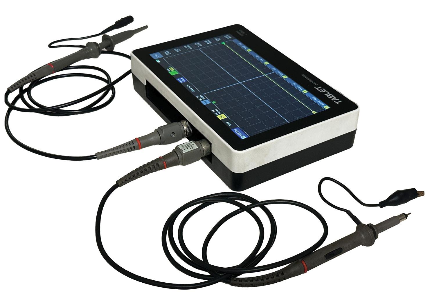
• Standalone portable units, selfcontained (pic 3).
• PC/laptop-based units, utilising the computer/s processing power and memory.
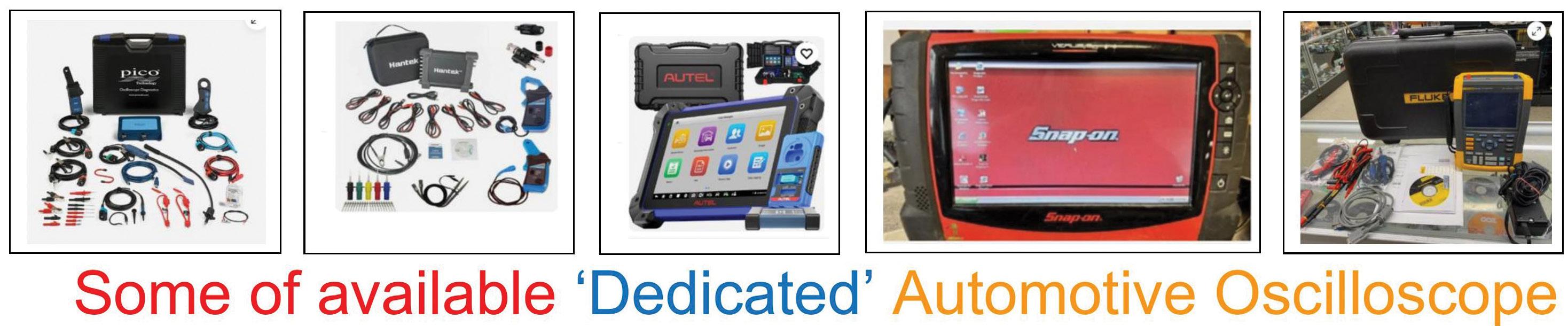
Additionally, consideration should be given to whether the user prefers manual control of settings on the X and Y axes or automated set-ups via pre-configured options (pic 4).
More on this in part two.
In summary
For automotive diagnostics, a DSO should, as a minimum guideline, offer:
• 50MHz bandwidth.
• up to 500MSa/s sample rate.
This helps ensure accurate waveform representation and minimises distortion (pic 2).
Until next publication, please do surf the net, examine the available DSOs and contemplate which of the many options may best suit your application. Until then, happy surfing.
Please note
For further information on dedicated automotive oscilloscope training videos, please refer to TaT technical videos.
MTA Institute (Registered Training Organisation 31529) is Queensland’s leading industry-owned provider of automotive training and plays a critical role in developing the skilled workforce that underpins Australia’s automotive sector.
The organisation has a strong focus on practical, real-world learning and delivers nationally recognised training across the technical, retail and aftermarket sectors, ensuring students and employers benefit from high-quality, industry-relevant education.
MTA Institute’s training model is built on flexibility, accessibility and direct industry engagement, supporting learners at every stage of their career – from entry-level exposure through to advanced, specialised skills development.
For those entering the industry, MTA Institute offers accredited introductory programs tailored to high-school students and job seekers.
These courses are designed to provide a valuable first step into automotive careers, equipping participants with foundational knowledge, practical skills and clear pathways into further training or employment.
By engaging students early, MTA Institute helps build awareness of the diverse opportunities available across the automotive sector.
At the core of the organisation’s offerings are its apprenticeships and traineeships, delivered one-on-one in the workplace. This model is designed to ensure learning
is directly aligned with realworld industry practices, allowing students to develop skills in real time under the guidance of experienced professionals.
For employers, it provides the opportunity to train staff in line with specific business needs, improving both productivity and retention.

Beyond entry-level training, MTA Institute delivers a range of specialised post-trade programs, including training in battery/hybrid electric vehicles (BEVs/HEVs), automotive a/c and advanced driver-assist system (ADAS) technology.
As the automotive industry continues to evolve, MTA Institute is leading the way in emerging technologies, particularly in BEV and HEV training.
With demand for EV skills only increasing, the organisation aims to equip technicians with the knowledge and expertise required to safely service modern vehicles and adapt to ongoing industry change.
One of MTA Institute’s most in-demand courses is the AUR20220 Certificate II in Automotive Air Conditioning Technology. This short course provides technicians with the skills and knowledge required to service
and repair automotive a/c systems while meeting national regulatory requirements. It also allows businesses to expand their service offering and respond to growing customer demand.
Complementing these pathways, MTA Queensland delivers specialised training in ADAS technology.
This training is designed to equip technicians with the skills to understand, diagnose, and work with systems such as lane assist, adaptive cruise control and collisionavoidance systems, reflecting vehicles’ increasing reliance on sophisticated safety technologies.
These programs are delivered at MTA Institute’s state-of-the-art facility at Eight Mile Plains and designed to enable qualified technicians to upskill, remain competitive and confidently adapt to rapidly advancing vehicle technologies.
For businesses, investing in ongoing training ensures teams are equipped to service modern vehicles and meet evolving customer expectations.
The benefits of workplace training extend well beyond technical skill development. For learners, it provides the opportunity to earn while they learn, gain practical experience and build confidence in a realworld environment.
For employers, it supports the development of a capable, engaged and loyal workforce while ensuring training is directly aligned with industry needs.
MTA Institute’s commitment to industry-led training and its diverse program offerings position it as a trusted partner in workforce development.
By delivering practical, relevant and forwardthinking training solutions, it continues to support the growth and sustainability of Queensland’s automotive industry – now and into the future.
• Find out more at mtai.edu.au

Iremember conversations some years ago, both socially and with customers, where people would say something like, ‘You’ll be out of a job as soon as electric vehicles (EVs) take over.’
That opinion was probably driven by media discussion at a time when it was unclear how EV and hybrid technology would affect an industry I have been part of for 38 plus years. Fast-forward to now and the picture is clearer, so it was a surprise to have a customer only recently make the same comment.
As technicians, we need to make it clear this is definitely not the case. The future is bright, although technicians and workshop owners may need to pivot a little. There will still be plenty of repairs and servicing opportunities, whether the vehicle is internal combustion engine (ICE), EV, hybrid or something else.
Trawl through social media and you will find two opposing EV myths. One says they never wear out consumables because of regenerative braking. The other claims they are tyre-eaters that destroy suspensions and bearings. The reality sits in the middle. EVs and hybrids change what wears and how it shows up.
Start with brakes. Regenerative braking lowers brake-pad wear and many customers appreciate the reduced dust and longer pad lifespan. The challenge is that brake hardware and rotors spend more time in a lower-use, cooler and wetter environment. Disc faces and pad surfaces are lightly used and exposed to the weather, which can lead to corrosion, glazing and increased squeal. It is not uncommon to see EV rotors appear worse than those on equivalent ICE cars at the same mileage, even though the pads still have plenty of life. Coated rotors and
hub assemblies can resist pitting and hat corrosion. Hat corrosion can cause rust stand-off, where rust grows on the mating surfaces of the axle flange and the inside face of a hat-type disc rotor. This can push the disc outwards, creating runout, brake pulsations, disc-thickness variation (DTV) or noise. Low-noise pad formulations developed for lower use help prevent early glazing and keep brakes quiet when the antilock braking system (ABS)/regen blend is functioning properly.
Treat the hardware as a wear item too. Guide pins, rubber boots, pad springs and stainless shim-hardware kits are not optional extras, especially with late-model EVs and hybrids often parking with the electric parking brake (EPB) engaged. Blended brake systems add complications. Vacuum boosters are disappearing, while electro-hydraulic units such as iBooster change pedal feel and can hide pad glaze until it suddenly becomes obvious. EPB actuators make pad retraction and adjustment a scan-tool task, so procedures need to be clear to prevent faults. Do not forget brake fluid. Regen does not affect hygroscopicity, so scheduled brakefluid changes remain important. Vehicles that specify low-viscosity fluids, such as DOT 4 LV/Class 6, need the correct fluid so the ABS and electronic stability control (ESC) respond predictably. Pads may last longer but rotors, hardware and the right fluids still require attention.
Tyres and alignment are where owners quickly notice differences. Extra kerb weight and instant torque drive tyre demand, while cabin quietness makes minor tyre noise obvious. EV-rated tyre constructions are not just marketing hype. Reinforced carcasses and higher load ratings matter when a vehicle is a few hundred kilos heavier than its ICE twin. Low rolling-resistance compounds help range, while foam inserts and quiet tread patterns reduce noise.
In practice, this means shorter tyre-rotation intervals and careful attention to alignment specifications, especially after suspension work. If you fit poly bushings or uprated shockers, document the new alignment targets. EV-rated tyres, hub rings, tyrepressure monitoring system (TPMS) service
kits and alignment hardware to correct camber and caster will save headaches and delays.
Wheel bearings and hub units endure more stress as kerb weights increase and torque delivery shifts from zero to peak instantly. Low-speed rumble or steering roughness may appear sooner if the car regularly travels on poor surfaces. Use quality hub units with encoder rings where applicable, and have new axle nuts, bolts and the correct antiseize ready.
Suspension and steering components also become more significant. Springs and shockers carry more weight, so fatigue and initial shock wear can appear earlier on loaded EVs and delivery vehicles. Ball joints and tie-rod ends may not fail at dramatically higher rates but instant torque will reveal marginal parts and speed up failure on worn components. Cabin quietness also turns minor noise, vibration and harshness (NVH) into customer complaints. Choose replacement parts carefully. Uprated shocks and struts designed for EV weights help maintain ride height and control and quality polyurethane bushings can lengthen component life, although customers should be warned about possible NVH. If a vehicle has advanced driver-assist system (ADAS) technology, changes in ride height or toe can affect radar or camera systems, so include post-repair alignment and ADAS calibration in your estimates.
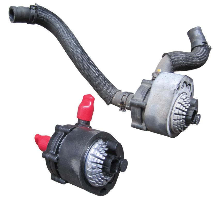
Thermal management and heating, ventilation and a/c (HVAC) systems need more attention in most hybrids, while pure EVs use advanced cooling systems. Battery cold plates, glycol-to-refrigerant chillers, diverting valves and electric pumps can operate quietly until they do not (pic 1). Small leaks or coolant contamination can cause intermittent faults that resemble a/c failures. Always check OEM coolantchemistry specifications, use deionised water where specified and vacuum-fill the loop to prevent air pockets that could cause thermal issues.
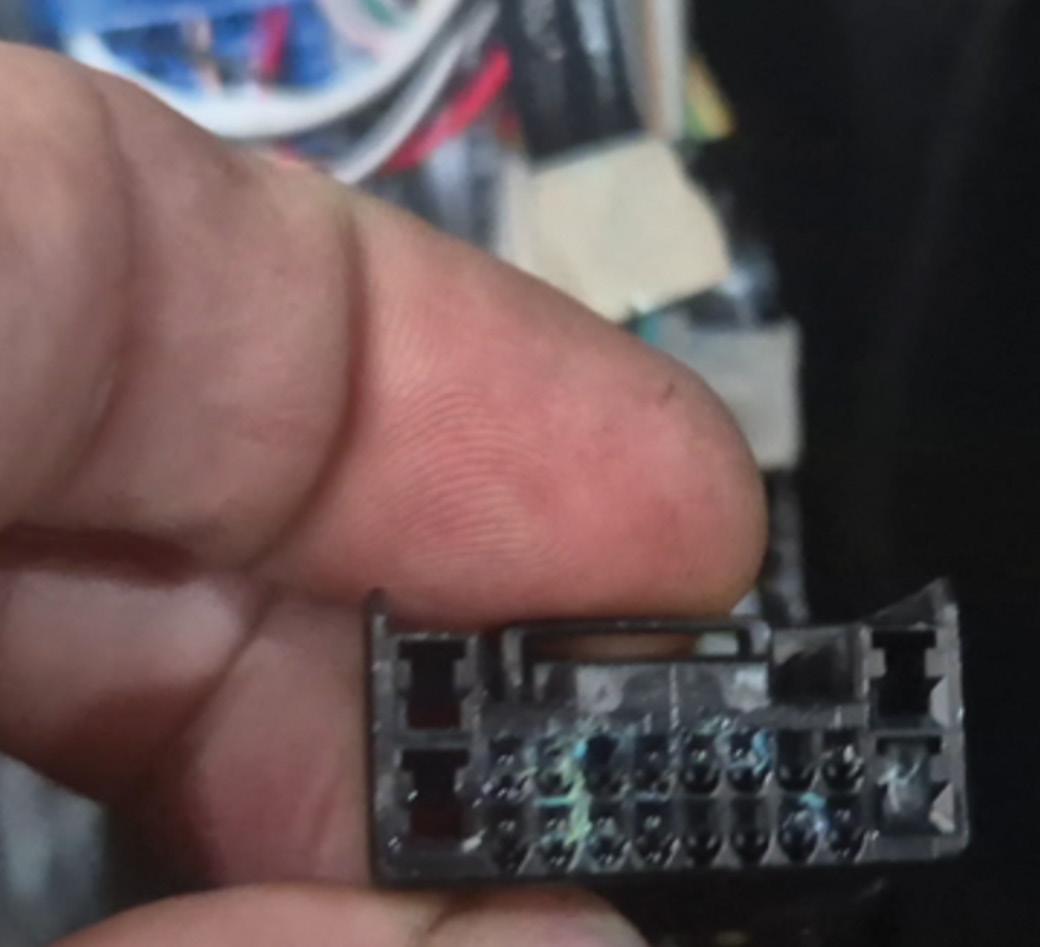
On the A/C side, the increase in high-voltage (HV) compressors and heat-pump systems raises the importance of correct compressor oil. Always use the manufacturer-specified oil for an electric compressor. Do not substitute polyalkylene glycol (PAG) oil, as crosscontamination can lead to insulation failure. Replace receiver driers or accumulators when the system has been opened, and remember HVAC can work harder for demisting and dehumidification.
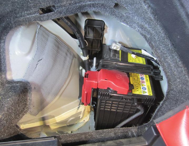
The modest and often overlooked 12V battery is important in EV and hybrid vehicles (pic 2). It is not a cranking battery in most cases, but it powers control electronics, contactors and security systems. A marginal 12V battery can immobilise a car even with a full HV battery. Test it on arrival, print the test ticket and recommend replacement proactively. In my experience, absorbed glass mat (AGM) batteries tend to fail with little or no warning, so in my business I have adopted a time-based replacement schedule, after consultation with the customer.
Hybrids keep many engine-related consumables selling, including oil and oil filters. The ICE in a hybrid tends to operate cooler and in shorter cycles, which can lead to fuel dilution and moisture if service intervals are extended. Use low-viscosity, low-SAPs oils prescribed by manufacturers, such as 0W-16 and 0W-20 for many Toyota and Honda models, and quality filters. My oil supplier has an oil specifically designed for the unique demands of hybrid vehicles.
Iridium spark plugs still last but can carbon up faster with short cycles of use, so do not assume they last forever. The longer they remain in service, the greater the chance they may become seized, difficult to remove or, worse, break during removal. Exhaustcondensation corrosion is common on vehicles that mostly do short trips. If you notice stale-fuel issues on a plug-in hybrid electric vehicle (PHEV) that remains in EV mode for weeks, advise owners on fuel-tank cycling or using a fuel stabiliser.
Sensors and electrical components are becoming more valuable commodities on electrified platforms. Regenerative braking and stability blending depend on clean wheel-speed and inertial signals. Lowquality sensors can cause brake blending to feel strange or trigger unnecessary stability faults. Temperature and pressure sensors in thermal loops are equally vital. A flaky negative temperature coefficient (NTC) sensor reading from a battery chiller can lead to lengthy diagnostics. Use trusted or OE-brand parts and keep an oscilloscope ready to verify signal quality before ruling out a module.
Charging-port assemblies also wear out. Latches, seals and hinges experience repeated use, while water ingress and corrosion around connectors can create ongoing charge-fault or communication issues (pic 3). Treat the charge port with the same care as a fuel filler: check, clean and replace worn seals. Do not overlook body and under-tray aero components either. EVs rely on underfloor shielding to protect the battery and extend range, so check clips, fasteners, battery-pack fasteners and HV cable clips after previous repairs.
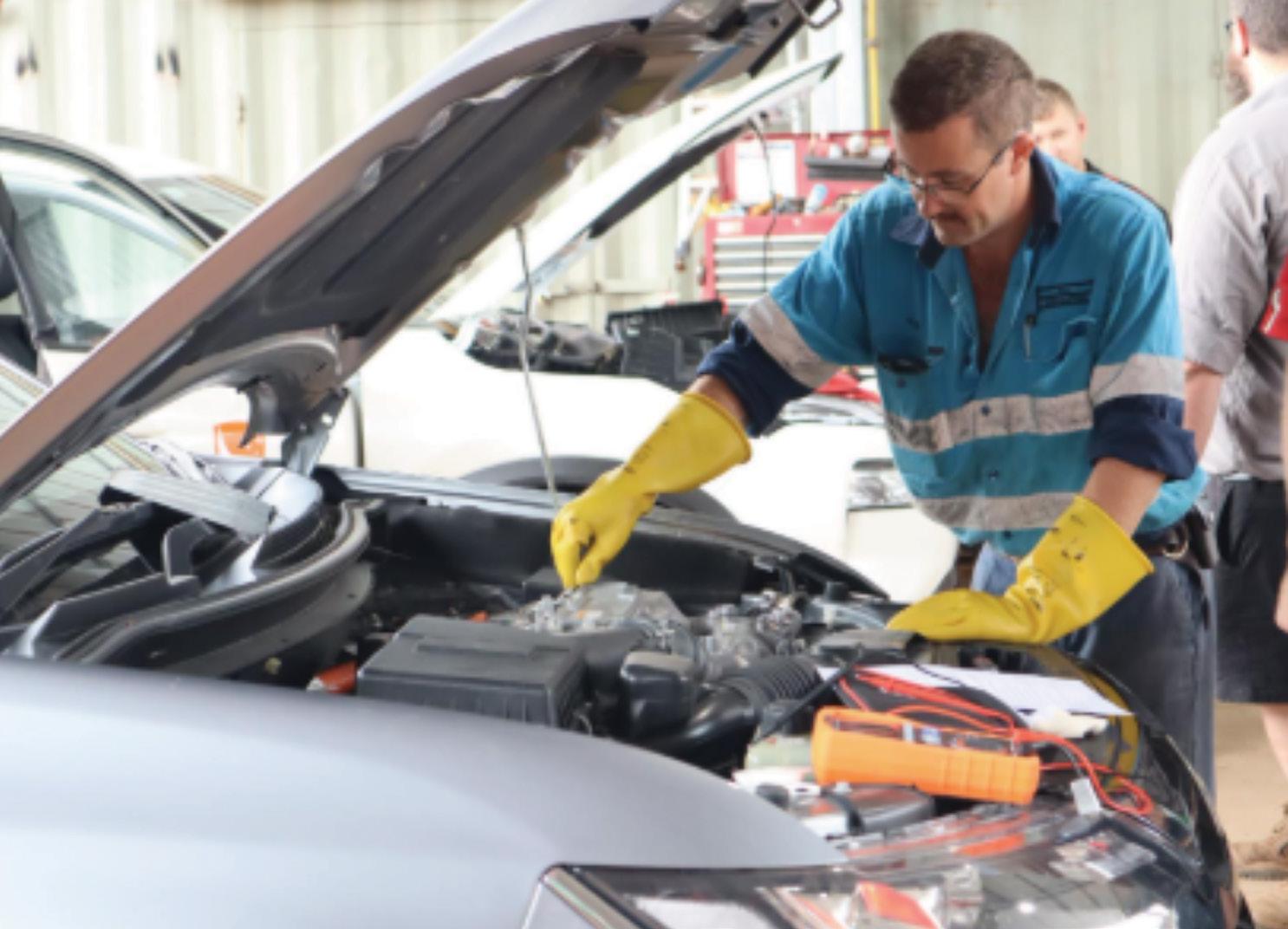
All of this seems like straightforward mechanical work with an EV twist. The key difference is preparation and procedure. Depower correctly, lock out the HV system and verify zero voltage before touching orange cabling or HV components. Use a scan tool that fully supports EPB, brake bleeding and thermal-actuator tests. For complex coolant loops, vacuum-fill and command pumps and valves to purge air.
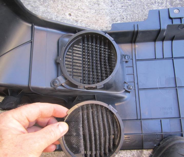
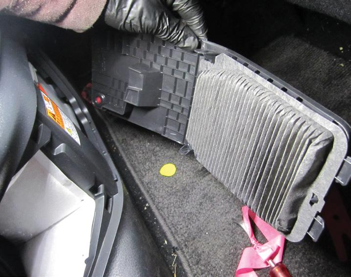
A modest personal protective equipment (PPE) investment, including Class 0 gloves, a rescue hook, insulated mats and signage, makes you credible. From a training perspective, the national entry units, the AURETH family for battery electric vehicle (BEV)/hybrid electric vehicle (HEV) work, provide a solid baseline. Note that many data portals are increasingly requiring proof of HV competency before granting access to certain procedures or service information. What does this mean for stock planning? EV and hybrid vehicles still have HV-battery air filters (pics 4 and 5), 12V batteries, braking systems, brake fluid, coolant in
much larger volumes than ICE vehicles, refrigerant, a/c components, tyres, suspension components, bearings and so on. What sold well 10 years ago has changed, so work out what to keep in stock to stay in touch with the market and remain profitable.
A sometimes overlooked fact is that many EVs still have oil in their drive units. Teslas, BYDs, Toyota’s BZ4X and Nissan’s Leaf to name just a few. These require attention at some stage, so be aware and plan ahead. Do not forget that 12V batteries deserve prominent placement because they prevent high-profile failures.
Finally, sell the service as a certainty. Create an ‘EV wear check’ that includes brakehardware inspection and de-glazing where needed, tyre rotation and alignment, a 12V battery test, cabin-filter and HV-battery air-filter checks where fitted, thermal-loop inspection and the usual safety items. When the job is bigger, tie the repair to a short explanation – why coated rotors resist corrosion, why specific oil was used in the a/c compressor, why a proper wheel alignment protects range or why HV training and safe work procedures are not optional. Those one-minute conversations build trust.
The bottom line is clear. EVs and hybrids are not parts deserts. They are different parts markets. Regeneration cuts brake dust but increases the importance of rotor coatings and hardware. Mass and torque alter tyre, alignment, hub and suspension needs. Thermal loops and e-compressors turn a/c work into genuine EV service. The humble 12V battery becomes the most important component your customer never considers.
Do that and EVs and hybrids cease to be ‘specials’ and start resembling what they will be in the near future – normal cars with a few new habits and reliable aftermarket opportunities for workshops that pay attention.
I believe our jobs are safe because vehicles will still require parts, servicing and maintenance and there will always be faults and failures. The industry may be changing but there is still plenty of work for those who keep up to date, train and stay in touch.
Dayco, one of the world’s leading innovators and manufacturers of motor-vehicle engine components, continues its pioneering technical innovation with belt-in-oil (BIO) technology.
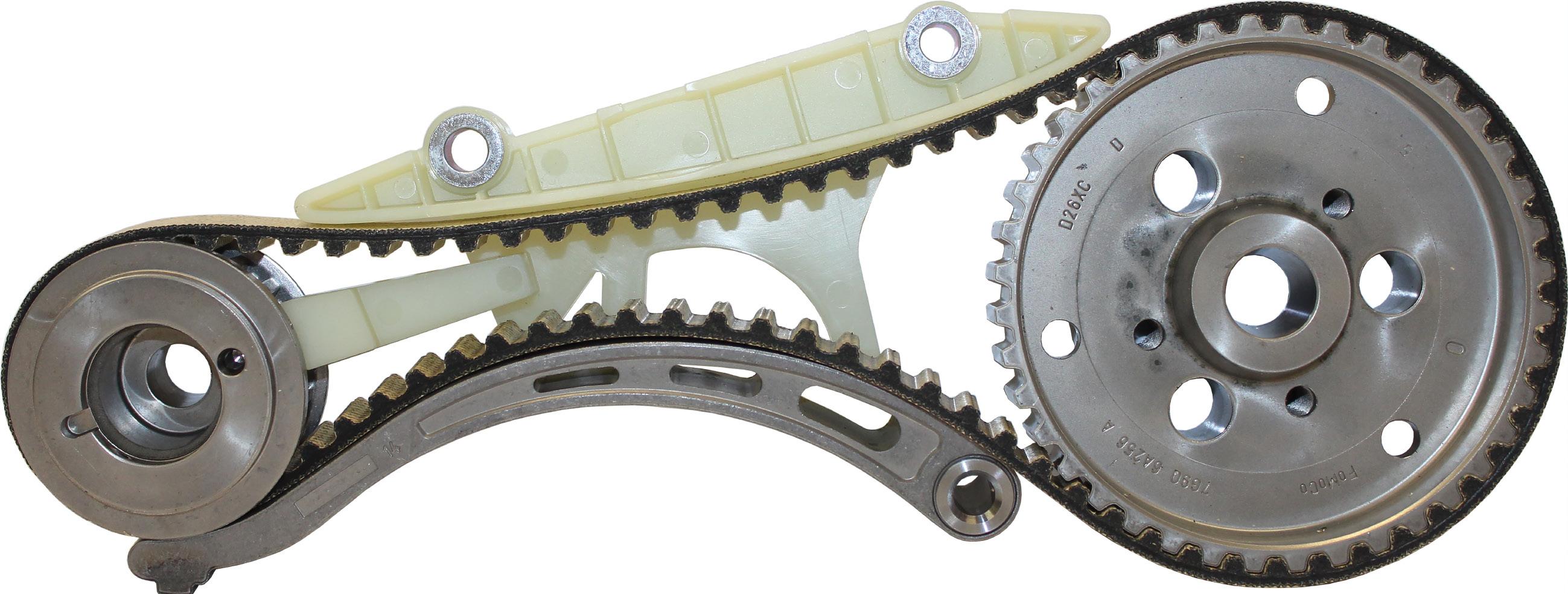
While some manufacturers prefer to use a traditional chain-drive system, several including Ford, PSA, Volkswagen (VAG) and now General Motors (GM) have embraced Dayco BIO technology and the benefits it can deliver, from weight saving and significant reductions in noise, vibration and harshness (NVH) to improved performance and emissions.
Emissions reduction, noise abatement and weight saving were key OEM goals with the Dayco BIO concept. Having to function in a chemically aggressive environment throughout the engine’s entire service life, and in contrasting climates across the globe, demands precise design and enhanced materials.
Accurately defining the real-world conditions these belts must cope with is therefore essential. Dayco’s development of a superior formulation that is more resistant to chemical attack from prolonged exposure to petrol and additives has resulted in these new and highly reliable OEM components.
The Dayco BIO system forms the mainstay of GM’s 1.0-litre and 2.0litre petrol engines produced for the Latin American (LATAM) region.
Local applications include the Ford Ranger/Everest 2.0-litre models and various VAG oil-pump drive applications.
The BIO system, which includes Dayco’s patented belt and tensioner, weighs less, has lower stretch, reduces friction and is quieter than traditional chain-driven components, translating into higher engine performance, lower emissions and improved fuel economy.
Built inside of the engine and in direct contact with engine oil, the Dayco BIO system also reduces engine packaging, resulting in fewer individual components and lower weight. Designed to operate inside the engine’s oil bath, it is constructed using high-performance HNBR polymer, specialised high-strength cords and PTFE (Teflon) film to withstand constant oil exposure and high temperatures. Dayco BIO system is designed to provide high resistance to wear, oil degradation and thermal aging with minimal elongation, ensuring accurate timing for the engine’s lifespan.
• Find out more at dayco.com.au


A 2014 Holden Cruze with 107,927km on the odometer arrived after repeated attempts to repair a misfire had failed to fix the problem.
Another workshop had pulled P0300 –Engine misfire detected and replaced the coil and spark plugs. The customer later fitted another coil to save money yet the check-engine light (CEL) and misfire kept returning until the car was finally towed in.
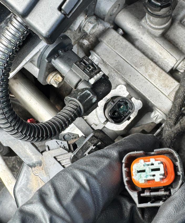
Initial checks uncovered a blown fuse for injectors #1 and #3, along with P0300 –Engine misfire detected and P0351 – Ignition coil 1 control circuit. Replacing the fuse would get the engine running again but only briefly, with the fuse blowing after two starts. Continuity checks on the injector harness to the ECU were all good but inspection of the removed coil pack showed #1 had melted through the side. The customer’s previously fitted coil had also melted in the same way, which initially pointed suspicion towards the ECU.
Sent the ECU away but it came back untested with advice that similar units had repeatedly been found fault-free. That pushed the diagnosis back to the vehicle, where closer inspection uncovered coolant contamination in the engine-coolant temperature-sensor connector on top of the thermostat housing.
Replaced the sensor and cleaned the connector but the fuse still blew after two starts.
Attention then turned to the ECU connector itself. At first glance nothing stood out but a zoomed-in photo revealed a tiny green dot on one pin. De-pinning the harness side exposed corrosion between two wires and wiring-diagram checks confirmed those circuits were for the coil and injectors.
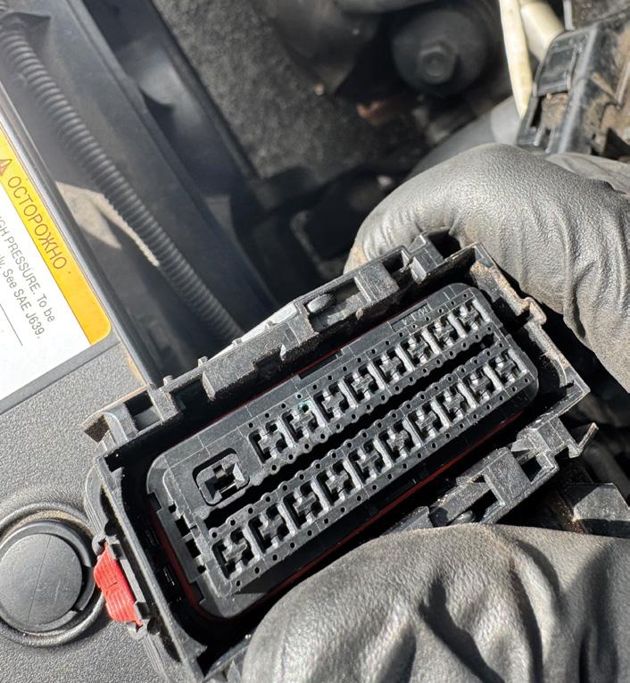
Cleaning the corrosion from the ECU connector, applying dielectric grease and replacing the coil fuse stopped the fuse from blowing. Then fitted a new coil and started the vehicle 10 times without fault, tested over two days with no further issues and the customer later confirmed it remained fixed after three more days of use.
Diagnostic time for this job was four hours and repair time 25 minutes.
David Simpson
Ultra Tune Midland MIDLAND, WA


This 2009 Holden Colorado would idle but refuse to rev past 1000RPM. The check-engine light (CEL) was on and the system was reporting low fuel-rail pressure.
Scan-tool checks revealed the fault codes (P0091 – Fuel pressure regulator 1 control circuit low and P1065 – Engine control module power supply circuit) and those clues shaped the direction of the job from the outset.
Initial testing showed the fuel-rail sensor, suction control valve (SCV) and related
wiring were all in good order yet the engine control module (ECM) was not providing an output to the SCV.
Attempted a rail-pressure relearn after replacing the SCV but it would not complete, which pushed the diagnosis back towards the control side rather than the fuel-system hardware itself.
Further checks of the ECM power supply, fuse box and grounds uncovered no corrosion or wiring faults.
Once the ECM was opened it was clear it had been tampered with and inspection of

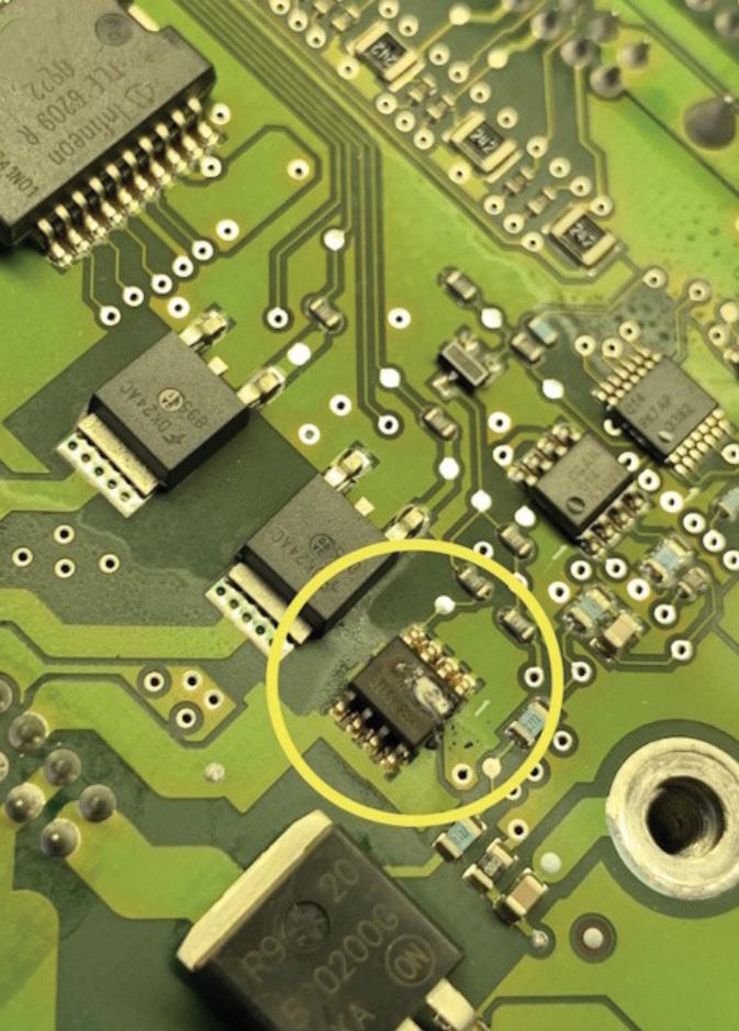
revved normally and all fault codes were cleared.
Diagnostic time for this job was two hours and repair time one hour.
Scott Halliday Hallimotive Auto Electrical BATEAU BAY, NSW
Petrol and diesel fuels contain remarkable energy but despite modern refining and additives, they are still crude-oil-derived products and never perfectly pure.
When burned inside an internal combustion engine, this imperfect fuel combustion leaves behind residues such as gums, lacquers, soot and particulates. These deposits create problems for both vehicle owners and technicians.
In earlier engines, deposits could build up so badly that engines required periodic stripping and decoking. Improved engine oils later helped by dislodging residues and holding them in suspension until servicing. However, oil can only clean where it flows, leaving the air intake and fuel system vulnerable. The widespread adoption of multipoint fuel injection in the 1980s improved fuel metering, while gasoline direct injection (GDI), introduced in the late 1990s, improved petrol engine efficiency further by placing injectors directly inside the combustion chamber. This gave the ECU greater control over the air/fuel ratio but removed a key cleaning benefit. In port-injection engines, petrol passes over the intake valves and helps keep them clean. In GDI engines, fuel no longer washes the valves. At the same time, crankcase ventilation introduces oily vapour into the
inlet, while exhaust-gas recirculation (EGR) adds soot. These particles stick to oily intake surfaces and gradually form carbon deposits. As deposits build, they restrict airflow and inlet-valve movement, effectively suffocating the engine. The engine-management system may compensate for a time but efficiency drops and warning lights can eventually appear.
Some manufacturers now combine direct and port injection to reduce this issue but many GDI engines still require manual decoking. Diesel direct-injection engines are also affected, although their oily sludge is usually easier to remove. Petrol GDI deposits are harder because higher temperatures bake them into a stubborn, rubbery layer.
JLM Lubricants Direct Injection Valve Cleaner spray is formulated to break down intake deposits. For best results, it should be followed by JLM Performance Fuel System Cleaner.
• Find out more at jlmlubricants.com.au


Geoff Mutton Business Resources
Don’t give the ATO more than you have to this EOFY
With June 30, 2026 fast approaching, now is the time for workshop owners to get their financials in order. The aim isn’t to avoid tax –it’s to make sure you’re not paying more than your fair share.
For a small automotive business, a bit of planning before year end can make a significant difference to the tax bill. Here are some practical, up-to-date strategies to consider over the next few weeks.
1. Book in with your accountant early
If you haven’t already organised a meeting with your accountant, make it a priority. June is their busiest time of year and many taxsaving opportunities need to be locked in before June 30.
A short planning session can uncover strategies specific to your business and the fee is tax deductible. More importantly, it gives you clarity and confidence heading into year end.
2. Take advantage of the instant asset write-off
Although the old temporary full expensing rules have finished, the instant asset write-off is still available for eligible small businesses (currently around $20,000 per asset but always confirm the latest threshold with your accountant).
For workshop owners, this can apply to items like:
• Hoists
• Scan tools
• Workshop equipment
• Office assets
If the asset is under the threshold and installed ready for use before June 30, you may be able to claim the full deduction this year instead of depreciating it over time. Just remember:
• Only buy what you actually need
• Make sure cashflow can support the purchase
• The asset must be operational before year end
3. Get wages and super up to date
Superannuation is only deductible when it is paid, not when it is recorded.
Before June 30:
• Ensure all employee super has been processed and cleared
• Double-check payroll for any missed payments or adjustments
• Review contractor payments to make sure everything is captured
Missing super deadlines is a common and costly mistake.
4. Consider pre-paying expenses
If your business qualifies as a small business entity, you may be able to claim deductions for prepaid expenses such as:
• Rent
• Insurance
• Interest on loans
• Training and subscriptions
This can help reduce your taxable income for this year by bringing forward next year’s expenses.
However, keep in mind you won’t be able to claim those expenses again next year, so it needs to be part of a broader strategy.
5. Write off bad debts
Now is a good time to review your accounts receivable.
If you have customers who clearly aren’t going to pay, you can write off the debt and claim a deduction this financial year.
Make sure you:
• Have taken reasonable steps to recover the money
• Document those efforts
• Record the write-off in your accounts before June 30
6. Clean up your stock
A proper stocktake can do more than tidy up your shelves, it can also reduce your tax bill. Look for:
• Obsolete or outdated parts
• Damaged stock
• Items that are unlikely to sell
Writing down or removing this stock ensures your profit isn’t overstated, which helps you avoid paying unnecessary tax.
7. Top up your own super contributions
Super is still one of the most effective ways to manage tax.
For the 2025-26 financial year, the concessional contribution cap is $30,000 (subject to current legislation) and you may be able to use unused caps from previous years.
Benefits include:
• Contributions taxed at 15 per cent
• Potentially lower than your personal tax rate
• Building long-term wealth while reducing current tax
This can be particularly useful if your business has had a strong year.

8. Lock in employee bonuses
If you plan to reward your team, now is the time to formalise it.
To claim a deduction this financial year:
• The bonus must be committed to in writing before June 30
• Payment can happen later
It’s a simple way to recognise staff and manage your tax position at the same time.
9. Energy efficiency and solar upgrades
With power costs continuing to rise, many workshops are looking at ways to reduce their energy bills.
While the broader energy efficiency tax incentives from previous years have now wound back, there are still solid savings available, particularly when it comes to solar installations. Federal rebates through the Small-scale Renewable Energy Scheme can significantly reduce upfront costs and the remaining investment may still be claimed through the instant asset write-off or depreciation.
In some cases, additional state-based rebates or financing options may also apply. The result is a double benefit – lower running costs and useful tax deductions – making energy upgrades worth considering if they fit your business needs.
10. Review your business structure and distributions
Depending on whether you operate as a sole trader, company or trust, there may be opportunities to:
• Distribute income more effectively
• Take advantage of different tax rates
• Retain profits within a company
This isn’t a last-minute fix but it’s worth discussing with your accountant to make sure your structure is still working for you.
EOFY tax planning doesn’t need to be complicated but it does require action before June 30.
A few well-timed decisions can make a meaningful difference to your tax outcome, improve cashflow and set your business up for the year ahead.
As with any complex job in the workshop, getting the right advice early is key. Speak to your accountant, review your numbers and make sure everything is in order before the deadline.
The red park-brake light on this 2015 Mazda CX-5 with 161,224km on the clock was flashing, the amber electric park-brake (EPB) warning light was on and the handbrake could not be released.
The behaviour in the vehicle’s supposed maintenance mode was also wrong, with the rear brake calipers only retracting briefly and then reapplying, which pointed away from a simple service-mode issue and towards a control fault.
A full code scan found repeated EPB switch faults, including C1128:29-8B –Apply and release switch and C1128:4A-48
– Apply and release switch.
After clearing the other faults and reattempting the release procedure, the
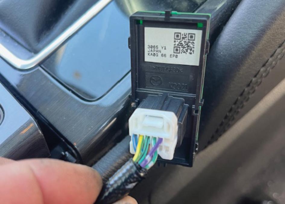
switch-related codes remained and live data from the EPB module showed the switch status as ‘error’.
Wiring information then showed the parkbrake switch uses two switches in series, so carried out continuity checks across the relevant terminals.
That testing showed no continuity on the light green/black to green/black circuit in the rest position when continuity should have been present.
Jumping the circuit allowed the codes to clear and changed the EPB switch parameter ID (PID) to ‘neutral’, confirming the wiring and module side were OK and the switch itself was the fault.
Replacing the faulty EPB switch (part number MZ-KAYG-66-EP0) restored
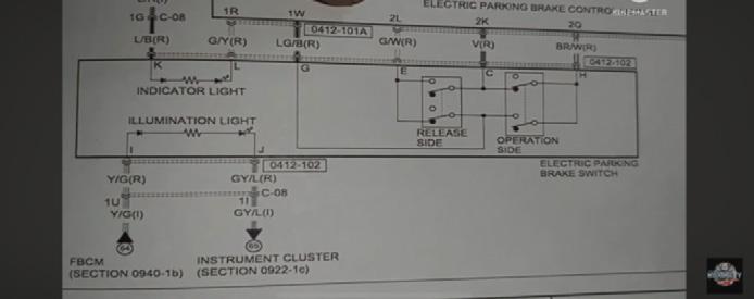
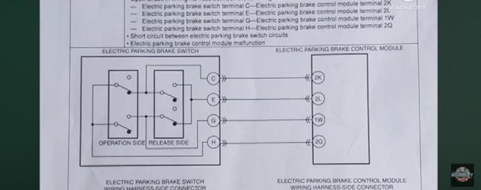
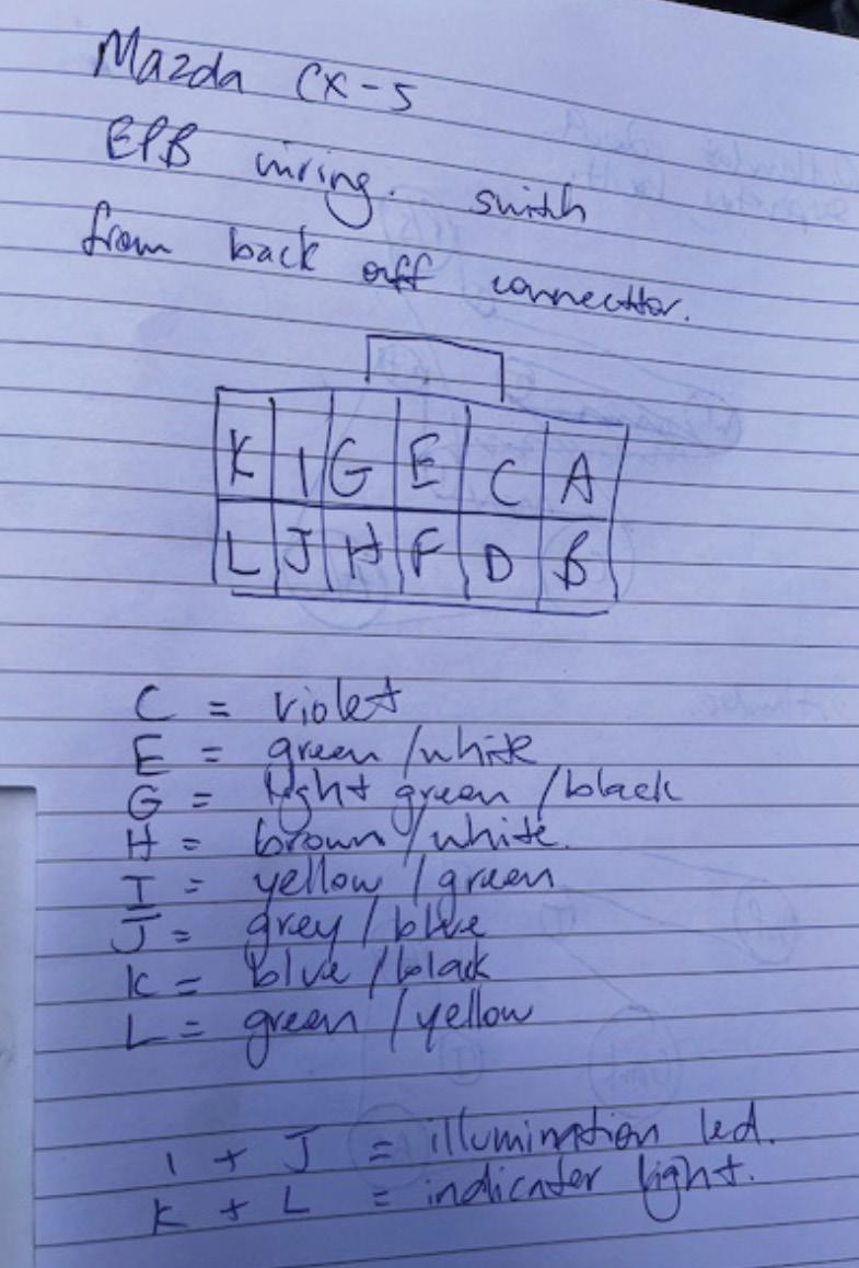
normal operation and resolved the warning-light issue.
Diagnostic time for this job was two hours and repair time 30 minutes.
Robert Ramsay Excel Diagnostic – Mobile Mechanic BRIGHTON, QLD

Many internal-combustion vehicle workshops have a specialist auto-electrician on their team. This is a real boon to a business, giving it the ability to offer a more complete service to customers and stand out in the market.
BAC likes to offer useful solutions to all skill sets and disciplines and auto-electricians are no exception. Recently, the company has received a number of requests for one particular solution shown in a photo on its website. The photo was taken 10 years ago in a truck workshop in New Zealand and shows a custom auto-electrician’s trolley developed by BAC for that workshop. The photo shows its age but it gets the concept across.
The item in question is the BAC TJ15008SB, more commonly referred to as the BAC Auto-Electrician Trolley.
This humble little runabout has partitioned drawers with enough locations for terminals and connectors, along with spool-bar space to hang small spools. This allows autoelectricians to take their go-to consumables right to the vehicle they are working on.
The unit is an example of how the modular nature of BAC storage cabinets allows them to be configured into many different layouts. If you have a specialty that requires fixed or portable storage, speak with a BAC sales representative. Describe your needs, show what you need to store and BAC can put together a solution by combining strong
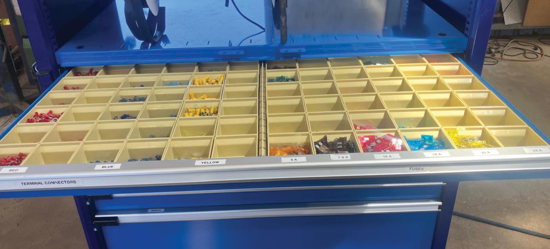
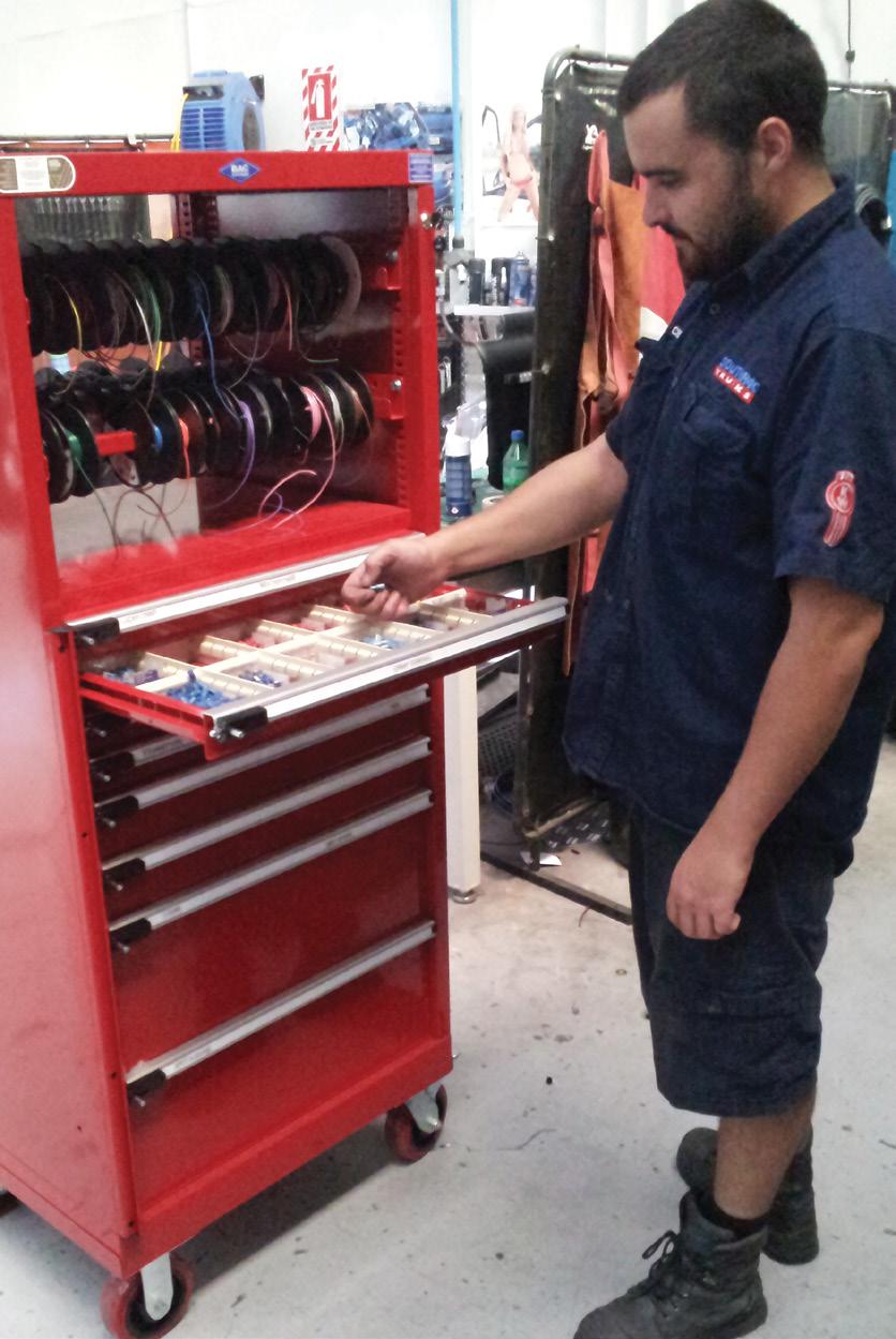
modular parts in a configuration that best suits you. This service is free, so why not take advantage of it?
BAC Systems is a solutions-oriented business that has come up with some fantastic concepts for its customers over the years, many of which found a permanent home in the BAC range.
Contact BAC Systems to learn how it can make work easier through a custom solution with its modular storage cabinets.
• Find out more at bacsystems.com.au or call 02 9832 2777
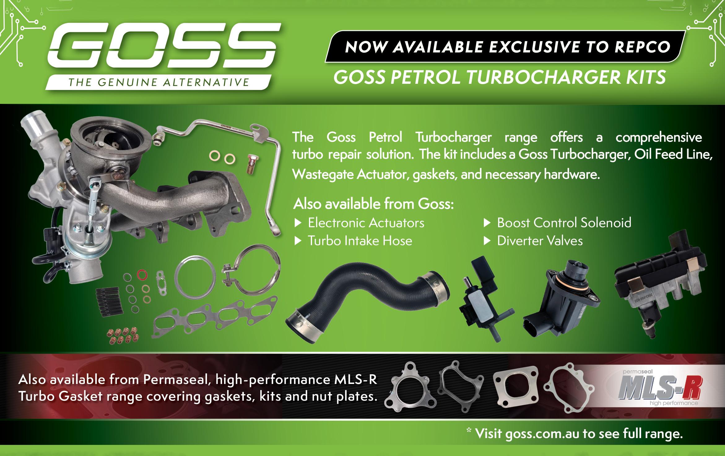
Protex has taken a different approach with the release of its new NS5 Nova Slot Rotor range – engineering a slotted rotor where real-world braking performance and reliability with visual appeal secondary.
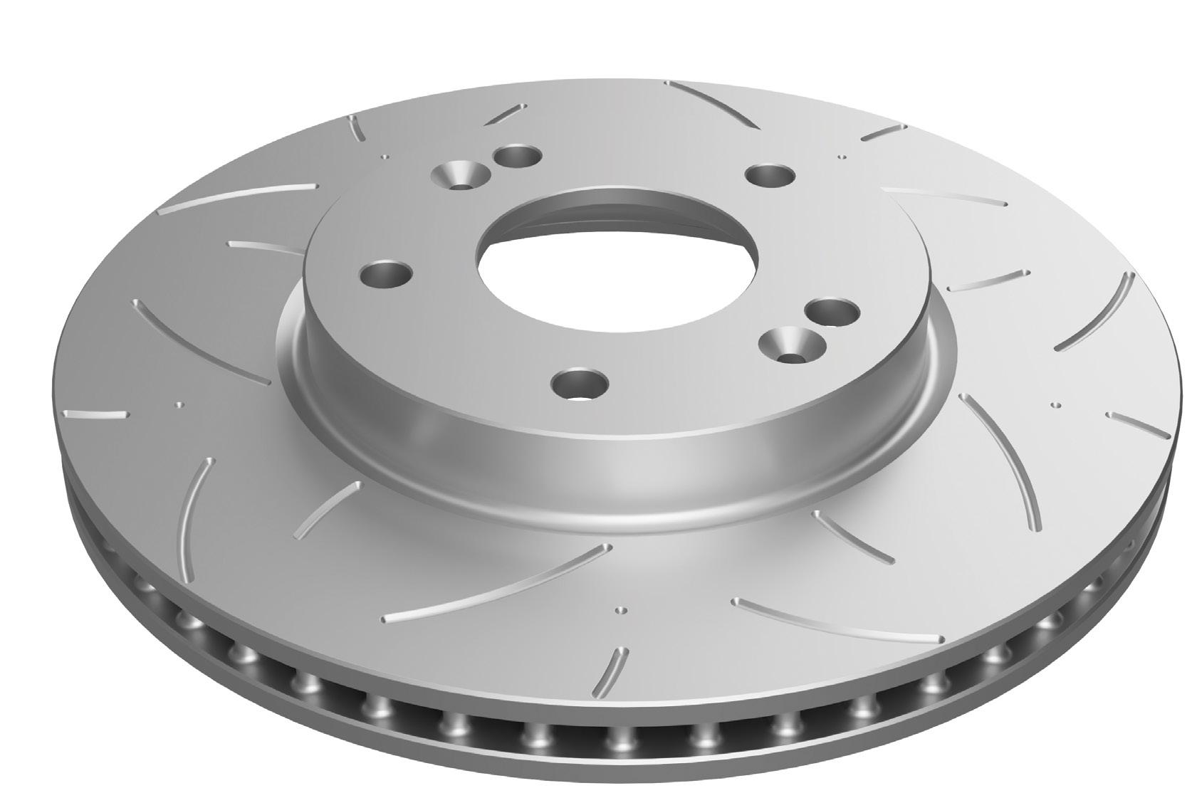
Developed in Australia, Nova Slot is the result of extensive design work, computeraided design (CAD) development, finite element analysis (FEA) and real-world validation. The objective was clear – create a non-directional slotted rotor that delivered measurable braking improvements without introducing harmonic vibration or uneven wear commonly associated with traditional slot designs.
At the core of the range is Protex’s proprietary NS5 slot pattern. ‘NS’ stands for Nova Slot, while the ‘5’ refers to the slot sequence repeated five times around the rotor face, with the same pattern offset on the inner face.
Using an odd-numbered, offset slot configuration is critical.
‘It helps dampen any harmonics in the rotor,’ said Protex Senior Product Manager John Harper. ‘The result is a rotor that delivers improved debris removal, gas evacuation, stronger initial pad bite and enhanced pedal response without added noise, harshness or instability.’
The NS5 bi-directional slot design is developed using a formula-driven CAD process, with a five-group slot pattern designed to optimise cooling, pedal feel and brake torque. Its bi-directional configuration also enables universal left and right fitment, simplifying installation and reducing inventory complexity for workshops.
‘It’s about making performance practical,’ said Harper. ‘You get the benefits of a high-performance slot design without adding complexity in the workshop.’
Before release, the NS5 design underwent CAD modelling and FEA to assess heat distribution and stress behaviour, followed by on-road and track testing. Validation included daily commuting in a Hyundai i30 N, heavy caravan towing with Toyota LandCruiser 200 and 300 Series models, circuit use at Mount Panorama, Sandown, Winton and Calder Park and sustained high-temperature evaluation of a Kia Stinger at Challenge Bathurst.
Every Nova Slot rotor is manufactured

using high-carbon metallurgy to provide increased thermal stability under repeated heat cycles.
‘The high-carbon metallurgy makes the rotor more stable when you give it thermal stress,’ said Harper.
This stability helps resist distortion, reduces the risk of warping and maintains consistent braking performance over time. Compared to standard G3000 cast-iron rotors, Nova Slot rotors better handle repeated heating and cooling, while controlled cooling during manufacturing helps minimise internal casting stresses.
Each rotor is finished with Protex’s Ultra Coat Z360 coating, providing corrosion protection, eliminating the need for cleaning oils before installation and maintaining a clean appearance behind alloy wheels.
A key workshop feature is the trademarked Smart Dot wear indicator system. Five indicator dots on both rotor faces provide a visual reference for minimum thickness.
‘It gives you a five-point wear indication,’ said Harper. ‘If one disappears, you know straight away that rotor is not running true.’
The initial NS5 Nova Slot launch includes around 106 part numbers, covering fourwheel-drives, performance vehicles and popular Australian platforms including Ford Ranger, Isuzu D-Max, Toyota LandCruiser, Holden Commodore, Ford Falcon and Toyota 86/BRZ models. Additional parts will continue to roll out.
Despite its engineering and testing credentials, the NS5 Nova Slot range remains competitively priced, typically positioned 20 to 25 per cent above standard replacement rotors while often undercutting comparable premium slotted alternatives.
The Protex NS5 Nova Slot Rotor range is available through AAD and a wide network of independent resellers nationwide.
• Find out more at protexparts.com.au