




MAZDA BT-50 Faulty MAF sensor stops shifts
ISUZU D-MAX Harness issue stops communication
FORD TRANSIT Fuse-box fail

puts focus on safe repairs and parts
Automotive Service Dealers Network (AASDN)
PATE 2026: Practical training with real workshop value










Editorial Board
Geoff Mutton
Jeff Smit
Technical Editor
Jeff Smit
Sub-Editor
Cameron McGavin
Scan Data Director
Rod Maher
Technical Research
Brendan Sorensen
Technical Contributors
Brendan Sorensen
Mark Rabone
Frank Massey (UK)
Jack Stepanian
Sam Nazarian
Jason Smith
Clinton Brett (Diesel Help)
Technical Assistance Team
Deyan Barrie Andrew Kollosche
Sideth Chiv Maurice Donovan
Gil Sher Anthony Tydd
Wayne Broady Jason Smith
Marty Hosie Jack Stepanian
Mark Rabone Jack Mackay
Daniel Armer Gary O’Riain
Scott Thomas
George Anagnostoudis
Associate Team Members
Gary Homan Peter Hinds
Columnists
Geoff Mutton (TaT Biz)
Advertising Enquiries
Paul Woods,
National Advertising Manager
E: pwoods@tat.net.au
Ph: 0494 044 958
Graphic Design
Brigid Fraser
E: production@tat.net.au
PH: 0413 009 122
Affiliated Associations
AAAA – info@aaaa.com.au
Capricorn Society Alliance Supplier
VASA – secretary@vasa.org.au





I’ve read many articles over the years about taking time away from a business and how it can benefit both you and your business and I’ve always been quite sceptical.
The last few years have been extremely busy for me. I’ve been overseeing the running of my busy workshop as well as my role in TaT, which continues to grow and includes many trips for training events, something I enjoy.
My workload over this time has been at a new level, even for me. But something I have also learned to do over the years is value time away from work. Some call it work-life balance, something I’ve never really mastered.
As many of you know, I’m a keen follower of football; some still call it soccer. Every four years I take time off to travel and attend the FIFA World Cup. I’ve attended the last five World Cups, so in 2026 it was time to head to Canada and the US to follow the Socceroos again. I’ve had the motivation to work hard, knowing some well-earned time off was coming.
First, it was a holiday to Canada with my wife and business partner Wendy. We cruised Alaska, then drove the Ice Field Highway, got snowed on at Lake Louise and got used to driving on the wrong side of the road. Then Wendy headed home and I headed back to Vancouver for the start of the World Cup.
The whole trip was fantastic but now I’m back at work and already planning the 2030 World Cup in Spain, Portugal, and Morocco. These trips really give me motivation to work hard and start saving for the next trip away.
The first decision for this trip was an easy one if it was going to be a true holiday – I would leave the mobile phone at home. That meant no calls and no emails. I left my phone at home and anyone who called got a message saying I was on leave and who they should contact, depending on why they called.
The same message was returned to anyone who emailed me. I get a lot of emails every day, so many people couldn’t believe I would


leave without my mobile. Well, I did and what a good decision it was.
Delegation in any business is important and a holiday gives your staff and those around you the opportunity to step up and prove they can deliver in your absence.
In my case, that’s exactly what happened. The reality is the sun will still rise, the work will get done and, you never know, you might even find a new inner self, think of new ideas, or finally realise that those around you can achieve the goals you’ve set.
The power of travel is often undervalued. It exposes us to new ways of seeing the familiar. Travel experiences often change how we see the past and envisage the future.
My holiday might be over but I’m still feeling the benefits. I’m refreshed and raring to go and have a sense of achievement and satisfaction. Don’t undervalue the positives of some time off, even a long weekend. It can really benefit you, your business and even your loved ones.
I’m now back at my desk and hitting the road for conferences and trade shows. I had the pleasure of attending the REDARC RedNetwork conference in Adelaide the week after I got back and it was truly fantastic. Some of the best automotive-electrical businesses from across Australia attended and it was great to contribute my bit to what was a great four days.
The real highlight for me was the tour of the REDARC factory. It had been around 10 years since I last visited and, wow, has it grown. It is a tribute to Anthony Kittel and the whole REDARC team.
I’m booked to attend many trade shows and training events for the remainder of 2026, so I hope to see as many of you as possible over the balance of the year. Make time for these events – there is always something to learn and you’ll get many opportunities to meet fellow technicians and share information.

Brendan Sorensen
Adead load used to be a fairly straightforward electrical circuittesting process. Check the fuse, check for power and ground at the load, test at the relay or swap it if there was an identical one nearby, then decide whether the component or circuit had failed.
That process still works on plenty of circuits but more often there is more to the story (or circuit) on modern vehicles.
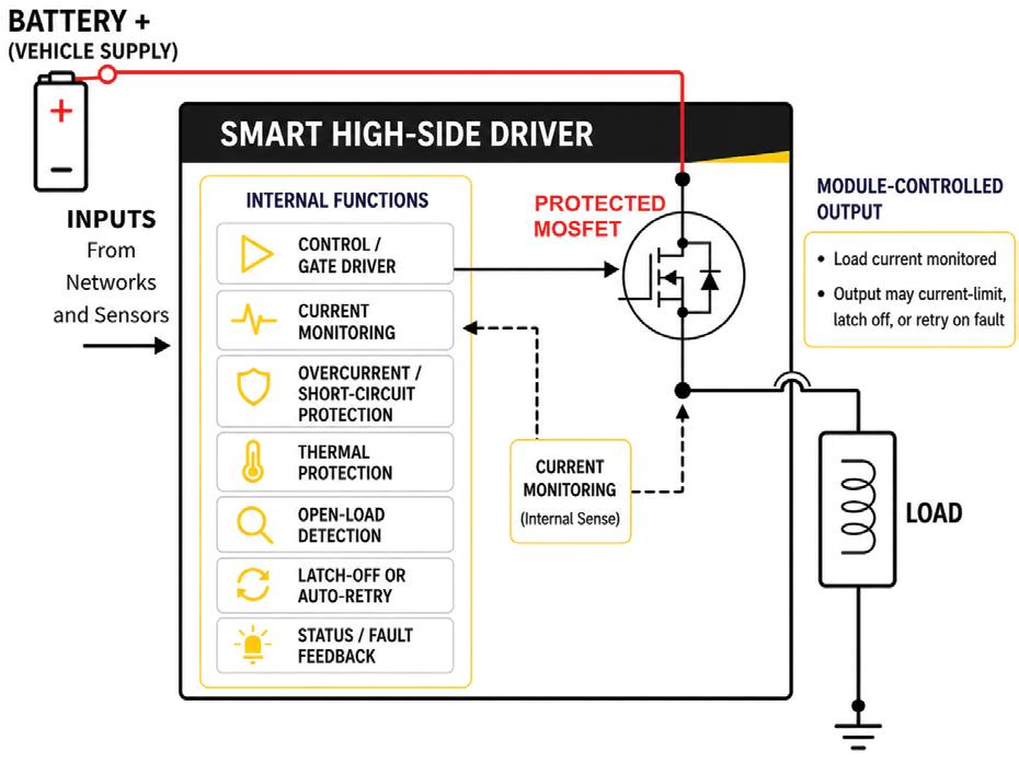
More body, lighting, cooling, pump and actuator circuits now sit behind a modulecontrolled output. Sometimes the module operates a relay. Sometimes it switches the power side through a high-side driver. Sometimes it switches the ground side through a low-side driver. Sometimes it uses pulse width modulation (PWM) rather than a simple on/off command.
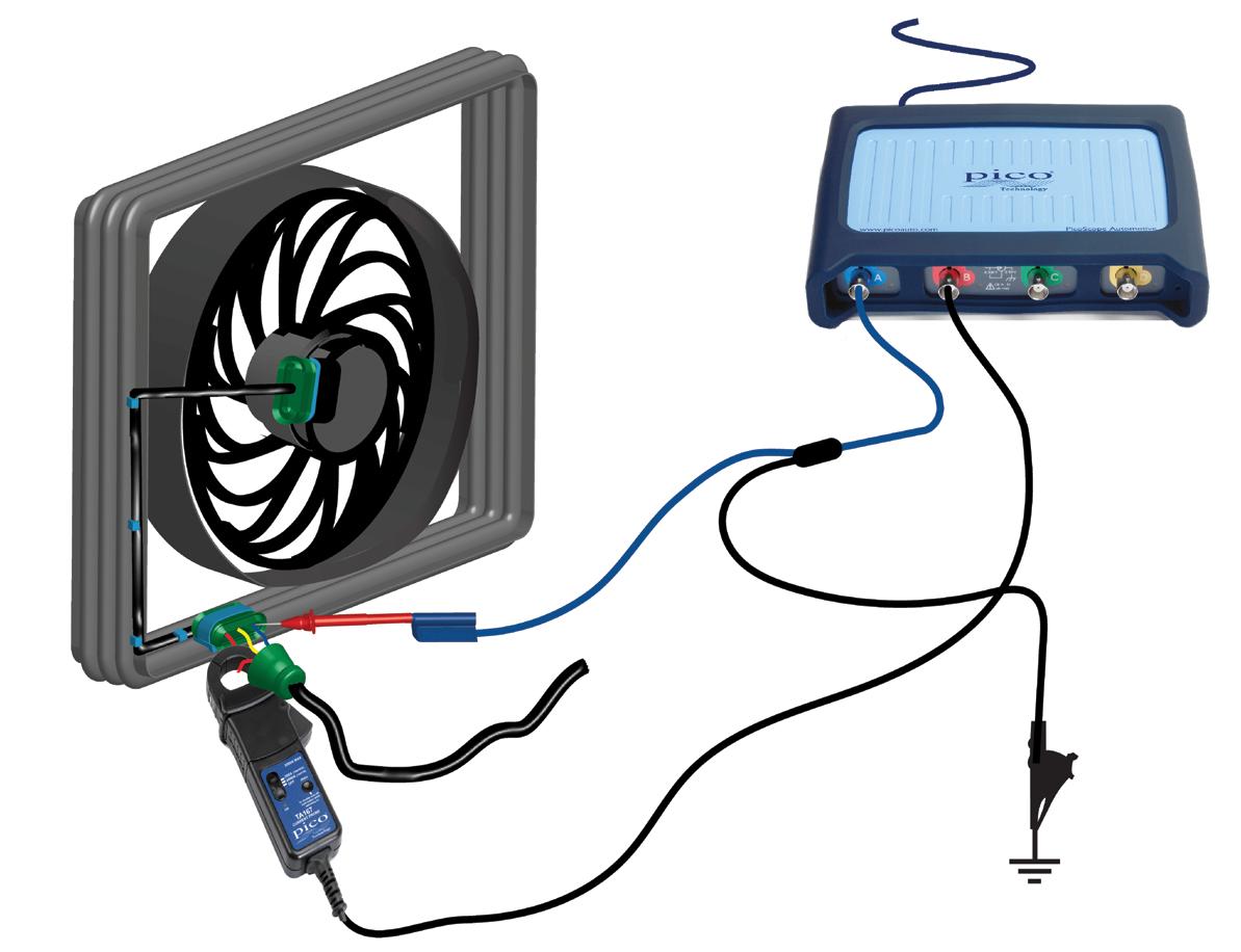
In newer power-distribution designs, the fuse function may be electronic, more like a resettable circuit breaker, with the output driver measuring current and switching the circuit off before the harness or driver is damaged (pic 1).
The module may receive the command to turn something on and even show the output as requested but that does not guarantee it is delivering usable current to the load. A digital volt meter (DVM) may also show voltage on the circuit even though the module is not switching the load on properly – on some circuits the module can apply a small sensing voltage to check whether the load is connected but that is not the same as supplying enough current to operate it. Depending on the fault and the module strategy, the output may stay off, pulse briefly, set a diagnostic trouble code (DTC), or remain latched off until the fault is removed and the correct reset condition has occurred.
The diagnostic question is no longer only, ‘Where did the power stop?’, we also need to understand what state the module output is in and why.
Before removing covers and panels to access a module-controlled load for testing, the wiring diagram should be the first port of call.
Identify whether the load is switched on the power side, the ground side, through a relay or by a separate smart module. If possible, also try to determine if the output is a simple on/off control or PWM.
On a high-side switched circuit, the module activates the component by supplying
power to the load while the ground path is permanent. On a low-side switched circuit, the load has a permanent power feed while the module completes circuit by giving a ground path.
A technician may see feed at the component and assume the power side is proven when the real control point is the module’s ground-side driver. Low-side switched circuits are more common to see as there are more electricalengineering complexities with a high-side switched circuit.
A cooling fan, pump or lamp on a PWM output may not receive steady voltage or ground, so the meter reading needs to be treated carefully. The module may vary duty cycle to control speed or output level. A DVM will average that signal into a number that may look confusing, while a scope shows the true story and the actual PWM switching.
If current draw does not change with duty cycle, the command may exist but the load is not doing the expected work.
Using scan data without overreading it
A scan-tool actuator test is useful because it gives you a repeatable command but it does not, by itself, prove the output driver has delivered current.
Where scan data is available, attempt to compare the input request, output command, output status and fault status. A switch input may change correctly, the body control module (BCM) may show the lamp requested and the actuator test may say the lamp is commanded on. That’s a useful start but it is still software-side evidence until the circuit is measured under load.
The next branch is whether the output is permitted. A module may refuse to drive a circuit because a DTC is current, the wrong operating condition is present, the vehicle is in transport mode, coding or configuration is wrong or a security gateway is blocking the function. Some outputs retry automatically. Some latch off. Some need the fault removed, then a key cycle, sleep cycle, code clear or specific OE procedure.
Reset behaviour is vehicle-specific, so it should not be assumed from another model or manufacturer. Use the scan tool to create or observe the command, then measure what the circuit does electrically while that command is present.
Testing voltage and current under command
Voltage testing still matters but voltage alone can be weak evidence on a monitored output.
A high-impedance meter can show voltage from a diagnostic bias, leakage path, monitoring circuit or unloaded output. That reading may tell you the circuit is being monitored or that there is the presence of voltage but it does not prove the circuit can carry the load.
For a motor, lamp, heater, solenoid or pump, connect a current clamp where it will measure load current during the command. If access is poor, measure at the fuse with a ‘fuse buddy’ or even at the module feed or load branch after confirming the diagram.
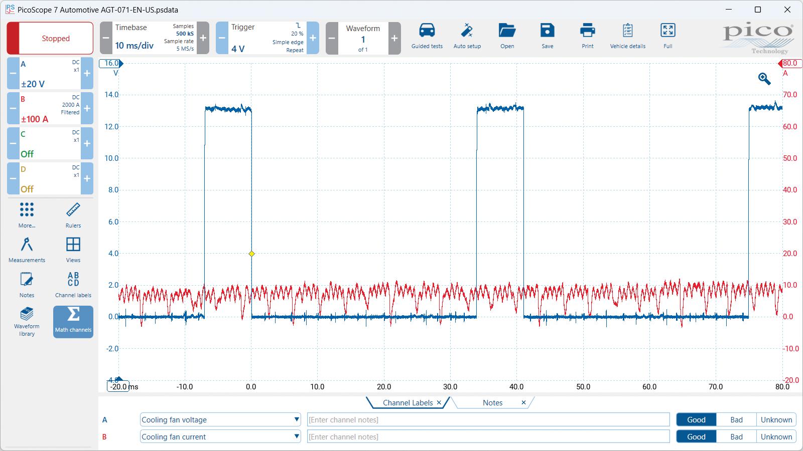
If the circuit is fast, pulsed or intermittent, use an oscilloscope (pic 2) rather than relying on a handheld current clamp display.
The voltage and current pattern is what separates the next branch. Command on with no voltage and no current points towards missing permission, an inhibited output, an open driver or even a poor module supply or ground that is not capable of carrying the load.
Voltage present when commanded with almost no current means your module is happy but points towards an open load, high resistance or perhaps you are looking at an unloaded diagnostic bias voltage on the circuit.
A current spike followed by shutdown points towards overload, a shorted load, a stalled motor or output protection. Repeated current pulses may be retry logic, PWM or the module testing the circuit.
Normal current with poor component operation should move your attention towards the component’s mechanical condition.
The ideal, as seen in pic 3, is for current (red) to increase or decrease in correlation with changes in command duty cycle (blue).
Smart outputs do not make voltage-drop testing obsolete, they just make it more important to test under the correct condition. A supply or ground that looks acceptable with no load can fall over when the component starts. A connector with terminal spread can pass a meter test, then open under vibration or heat. Corrosion can leave enough continuity for a DVM reading while limiting current badly enough to trigger a smart modules protection strategies or fault codes.
Command the circuit on and voltage-drop test it the same way you would any other loaded circuit.
On the positive side, place one meter lead on battery positive, the module power feed or the module load positive output and the other lead on the positive input at the load. On the ground side, place one meter lead on battery negative, the chassis, module ground circuit or where the ground side of the load terminates and the other lead on ground pin at the load.
You will notice I’ve given many options for meter-lead placement here, some with drawbacks that would require further testing to justify (such as additional confirmation that there is no voltage drop between chassis ground and battery negative) but this is the real world, where access and speed versus information gained drive many of our diagnostic decisions.
If a meaningful drop of over 300 millivolts (mV) appears across a connector, splice or wire, keep moving your meter leads closer together along the circuit to find the location of that drop.
An incandescent test light is still a very useful diagnostic tool but on module-controlled outputs it needs to be used with a clear purpose. I would not treat it as a universal
replacement for the original load and I would be especially careful on PWM circuits.
If the module is only commanding 20 per cent duty cycle in the bay, the test light may only glow dimly, which may be perfectly normal. That does not prove the circuit could run the original load at full demand.
Where the test light earns its keep is as a controlled load for a specific part of the circuit. For example, once the wiring diagram is understood, a suitable incandescent test light can help prove that a feed, ground, connector or section of harness can carry current. It is also useful for exposing a highresistance connection that looked fine on a DVM but experiences voltage drop when loaded by the test light.
The test should be arranged so you know exactly which part of the circuit you are loading rather than simply unplugging the component, fitting a globe in its place and assuming the module will behave the same way as a smart module may be capable of detecting the change in load impedance and shutting the circuit down.
Choose the test light to suit the circuit. A small LED test light may draw so little current that it proves very little, while a 55W headlight bulb may be too heavy for a small driver. Avoid back-feeding a modulecontrolled output as a general test and be cautious about changing the normal load path on smart outputs.
Used properly, the incandescent test light is not a crude shortcut. It is a simple, visible load that can prove current-carrying ability when the test is targeted and the circuit design is understood.
Faulty modules still exist. Smart drivers fail, output stages burn, internal current sensing can be wrong and water ingress into fuse boxes and body modules mounted in outrageously vulnerable positions remains common.
Before condemning a module-controlled output, I want to know the circuit architecture has been identified, the module has the required powers and grounds, the command is present, voltage and current have been measured under command, the load has been tested or substituted suitably, connectors and terminals have been proven via voltage-drop testing under reasonable load and relevant DTCs, live data and OE reset procedure notes have been checked. If the module is commanded, permitted, supplied and grounded, the load and wiring are proven and the output still cannot deliver the correct current, the case for a failed module becomes much stronger but without those steps a protected output can make a good module look faulty.
4x4
Jeff Smit
What are the latest trends and what issues are being seen by aftermarket workshops?
The 4x4 aftermarket in Australia and New Zealand in 2026 is no longer just about suspension kits, tyres, driveline repairs and accessory fitting.
Workshops are now dealing with a more complex vehicle mix –high-volume diesel utes remain the core of the market but they now sit alongside hybrid electric vehicle (HEV) and plug-in hybrid electric vehicle (PHEV) entrants, increasingly sophisticated advanced driverassist system (ADAS) equipped 4x4s and heavily accessorised touring vehicles that push compliance, calibration and load management to the forefront of the repair conversation. That shift is changing both the work mix and skills mix inside independent workshops.
The starting point is volume. Utes and 4x4-style light commercials remain central to the Australian/New Zealand service market because they are central to the new-vehicle market. In Australia, Federal Chamber of Automotive Industries (FCAI) data shows just how dominant the segment is, with Ford’s Ranger, Toyota’s HiLux, Isuzu’s D-Max and BYD’s Shark 6 all featuring strongly among the top sellers.
That means independent repairers are seeing a steady stream of familiar fleet and private-use workhorses but with more technology on board than the previous generation.
One of the biggest trends in 2026 is the serious electrification of the 4x4 and ute categories. The BYD Shark 6 has already become a visible part of the market and Ford’s Ranger PHEV has pushed plug-in hybrid technology further into mainstream ute servicing. For workshops, this does not mean diesel work disappears overnight, it means the job mix expands. Technicians now need to be comfortable moving between traditional diesel driveline faults and new concerns such as high-voltage (HV) safety procedures, hybrid cooling systems, battery-related diagnostics, regenerative-braking characteristics and manufacturer-specific software routines.
In practical terms, the workshop that used to focus on mechanical plus accessories now increasingly needs to shift the spotlight to mechanical plus electrical plus software.
At the same time, diesel remains the workshop’s bread and butter for those who specialise in 4x4s and diesel emissions-related issues remain a major pain point. Diesel particulate filter (DPF) complaints are recurring, especially with 4x4s and utes used for short-trip urban running rather than sustained highway work. Workshops are still seeing blocked DPFs, incomplete regenerations, warning lights, limp-home complaints and customer misunderstandings about how these systems operate.
This is particularly relevant for mixed-use dual-cab utes that spend weekdays commuting and weekends towing or touring. Diesel diagnosis also continues to overlap with injector problems, turbo faults, air-intake restrictions and exhaust-gas recirculation (EGR) related driveability complaints.
Another major 2026 trend is that modification work is increasingly interfering with factory safety systems. Bullbars, lift kits, larger tyre packages, added lighting, roof loads and changes in ride height have long been standard in 4x4 workshops. The difference now is that these modifications can affect radar, camera and sensor performance on vehicles fitted with ADAS features such as autonomous emergency braking (AEB), lane support and blindspot monitoring.
Research done here in Australia and New Zealand has specifically examined how changes to ride height, pitch, bullbars and additional lighting may affect ADAS operation on modified vehicles. For the aftermarket, this turns once-straightforward accessory jobs into calibration, liability and documentation tasks as well.
That has a direct compliance dimension in both countries. In Australia, workshops are operating in a landscape shaped by ADR requirements, while in New Zealand the low-volume vehicle (LVV) certification framework remains crucial for modified vehicles.
The practical takeaway for repairers is simple – customers still want bigger tyres, suspension upgrades and touring accessories but workshops increasingly need to ask whether the vehicle remains certifiable, inspectable and calibratable after the work is done.
A related issue is the reality of payload, towing and gross vehicle mass (GVM). Workshops are seeing more 4x4s built as multirole vehicles – weekday tradie ute, family SUV, weekend tow rig and long-distance tourer. Once bullbars, winches, canopies, drawer systems, long-range tanks and roof equipment are added, many vehicles are now operating much closer to their legal and mechanical limits.
That increases demand for suspension work, brakes, wheel

alignments, tyre replacement, cooling-system checks and driveline inspection. It also creates tougher customer conversations. The modern workshop is not only fitting parts, it is increasingly acting as an advisor on safe loading, towing set-up and the real-world consequences of accessory accumulation.
Software access is another area that has become more important. Australia’s Motor Vehicle Information Scheme (MVIS) was designed to improve independent access to service and repair information, including software updates and diagnostic data.
That is significant for 4x4 workshops because more jobs now depend on scan-tool capability, module coding, electronic component matching and access to OEM procedures. The opportunity is real but so is the investment requirement. Having access to data is one thing – having the tooling, subscriptions and staff training to use it profitably is another.
Underlying all of this is the skills shortage we have been discussing for some time, and it’s not getting any better. Capricorn’s 2025 State of the Nation reporting across Australia and New Zealand highlighted reduced productivity linked to labour shortages, stronger demand for training and the growing importance of electric vehicle (EV) and hybrid capability. New Zealand’s Motor Trade Association (MTA) has also continued to emphasise the shortage of skilled automotive people and the need for stronger training pathways.
In a 4x4 workshop, that shortage is felt twice – first, in finding technicians and, second, in finding technicians who can move confidently between diesel diagnostics, electrical work, accessories, wheel alignment, ADAS awareness and customer-facing compliance discussions.
The headline for 2026 is that 4x4 aftermarket repair is becoming more technical, not less. The vehicles are still rugged but the repair environment is more digital, more compliance-sensitive and more skill-intensive than many operators expected even a few years ago. The successful workshop in Australia and New Zealand will be the one that can still do the traditional 4x4 work well while also handling software, calibration, hybrid safety, emissions diagnosis and modification compliance with confidence.
That is where the market is heading and it is where the pressure points already are.


Clinton Brett Founder | Diesel Diagnostics Trainer Diesel Help Australia
I wrote an article a few years ago for this publication (TaT issue 71) in which I referred to an issue we experienced in Toyota 200 Series LandCruisers and Prados using two fuel tanks.
In these cases, the vehicle would stall and not restart until the tank-gauge level was above quarter full. This was due to fuel starvation caused by a blocked fuel-tank pick-up and the substance was engine oil. My extensive experience in diesel fuelinjection, including dismantling rotary fuel pumps back in the 1980s all the way through to 2013, told me this was an expected outcome but it rarely caused these symptoms common-rail diesel (CRD) applications.
In this article, I’m highlighting a problem Diesel Help members are increasingly witnessing when they come on board for help to diagnose CRD. They have become confident tackling older diesels but knowing how the CRD system operates is an entirely new experience. Only we older-generation diesel specialists can explain this in simple terms.
This old-diesel diagnostic training has become popular with our members in the past three years. I have delivered exclusive training to members – Clint’s Systematic Approach to Diagnosing Diesels – in which they must present an old non-CRD as part of the day’s proceedings. Some have opted for all old-diesel training and this has involved me teaching them how to dismantle and reassemble these older rotary pumps.
Models
Nissan Patrol, Navara, Urvan and Terrano with TD42T, TD42, TD27, TD27T and ZD30 engines, 1989 to 2006
Symptoms
Engine is difficult to start. White smoke is evident while cranking. If the engine does start, it will run very rough, stalling occasionally.
1
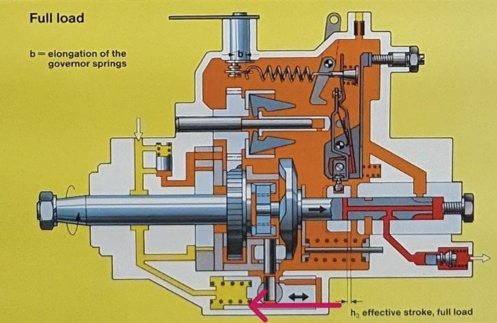
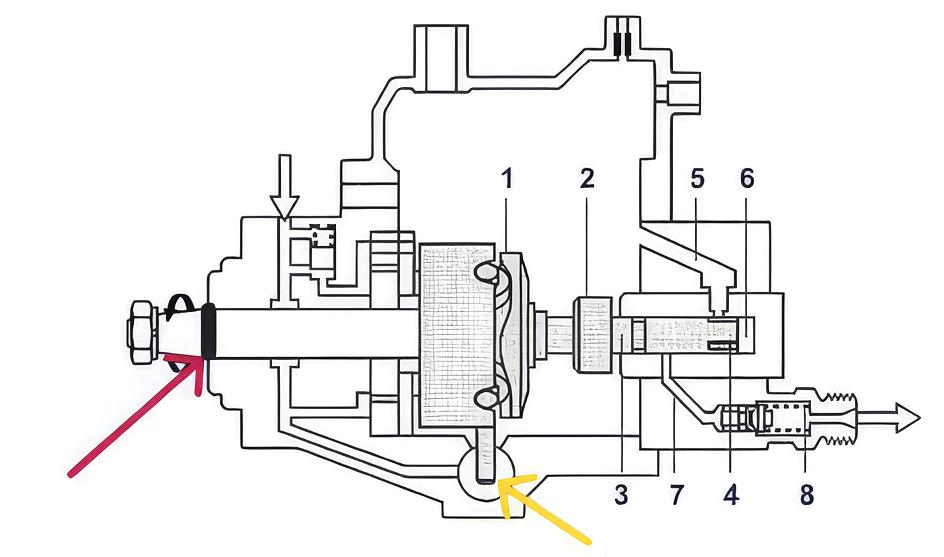
A worn front driveshaft seal and driveshaft (pic 1, red arrow), which causes air to enter the injection pump, preventing the fuel system’s advance-timing mechanism (pic 1, yellow arrow) from operating correctly.
Diagnosis and/or early detection of the fault
It’s important to understand how this fuel system operates to understand the diagnostic pathway for this failure.
These engines are fitted with a Bosch VE rotary-design pump, which uses an internal hydraulic timing piston to change the position accordingly with engine speed.
Air enters the front of the fuel-injection pump, causing retarded injection timing during cranking to start and idle the engine.
The fuel pressure is developed by the internal fuel-transfer/suction pump, which draws fuel from the tank and through the filtration system before entering the pump. The fuel travels through several passages to the advance-timing piston.
When air enters a hydraulic operating system, the hydraulic ability is greatly reduced, meaning there will be inadequate fuel pressure to push the heavy internalreturn spring into advanced timing at low RPM (pic 2).
The red arrow in pic 2 shows the direction in which the fuel pressure moves the piston for advanced timing.
Once the engine RPM is increased, the air is eventually purged but the engine will have also warmed up slightly, helping with improved compression and combustion temperatures.
When retarded timing occurs, fuel injects late into the combustion chamber, creating unburnt fuel and slowing down the engine speed. This is caused by the hydraulic locking of the engine and if ignored too
long, washing of the bores can be a longterm result.
This is common wear with all rotarydesign fuel pumps, including those used in common-rail applications where the driveshaft is exposed to engine oil. It often occurs at mileages above 200,000km but it is also dependent on the condition and quality of oil.
Older engines are susceptible, particularly those prone to sludging, which is a combination of overdue oil changes that results in excessive carbon content and has a harsh impact on moving parts.
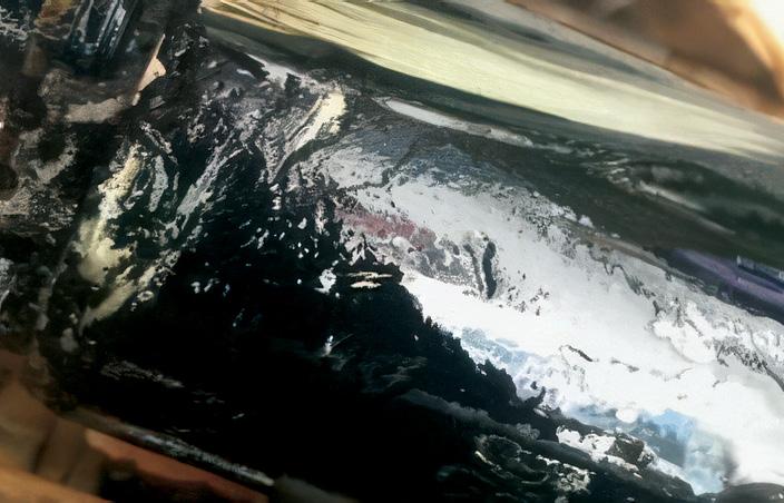
The gritty oil becomes trapped between the pump’s driveshaft and the rubber radiallipped seal, grinding a large groove deep enough to feel with your fingernail (pic 3).
Carbon can cut diamonds, so steel has no chance and this large groove is formed. This results in oil entering the fuel pump and increasing wear to internal parts. It also allows air to enter, causing the excess retarded timing.
This issue becomes worse during winter months due to the expansion and retraction of the seal. Cooler temperatures also mean reduced engine compression, which adds to the problem.
You will notice the fault more frequently when there is a low tank of fuel and when parked on a hill facing downwards (i.e. the tank is at the lowest point). If you connect a separate fuel supply, it will also be easier to fault.
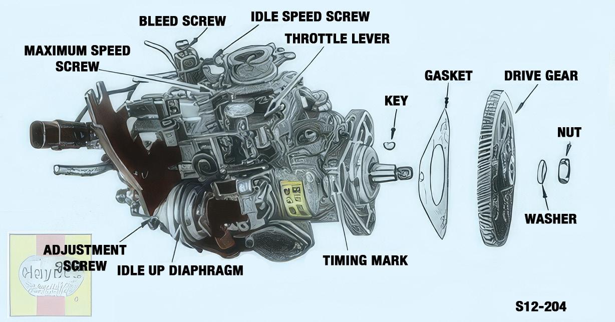
When connecting the supply (i.e. Diesel Help’s The Eliminator), ensure you are connected directly to the front banjo bolt (inlet) and the rear banjo bolt, which can be referred to as a bleed screw or return overflow valve (pic 4)
This valve uses a restriction port to allow the cam box to retain pressure. It has gauze in this return, which is worth inspecting when removed. Inspect the colour of the fluid on the internal part of the banjo bolt. If it is not clear but grey or darkened, oil is present, which will help with the final decision. After connecting the separate supply, test drive the vehicle to ensure all air is removed
from the system. Then leave it parked overnight with The Eliminator tank on the floor or at least below the inlet of the fuel pump on the engine. Then start the engine and look for air entering and exiting the fuel pump – this is why it is important to use a clear hose.
If the engine cranks but is difficult to start, raise the supply above the injection pump’s position on the engine and you should experience an improvement. We advise replicating this again with the tank in the raised position.
Please be aware that if the seal is severely worn, raising the supply level may cause the
engine sump to fill overnight, so checking the engine oil level each time before starting the engine is recommended.
To rectify the fault, you will need to remove the fuel pump and injectors and send them to a diesel fuel-injection specialist for overhaul. You will also need to remove and clean all fuel lines and the fuel tank.
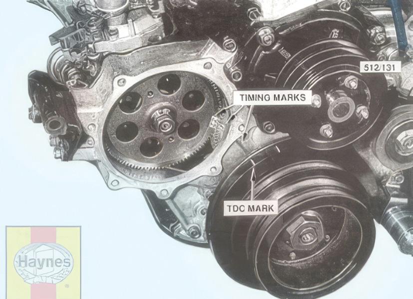
This fault is common on all injection-pump applications where the fuel pump drives off timing gears and chains (pic 5).

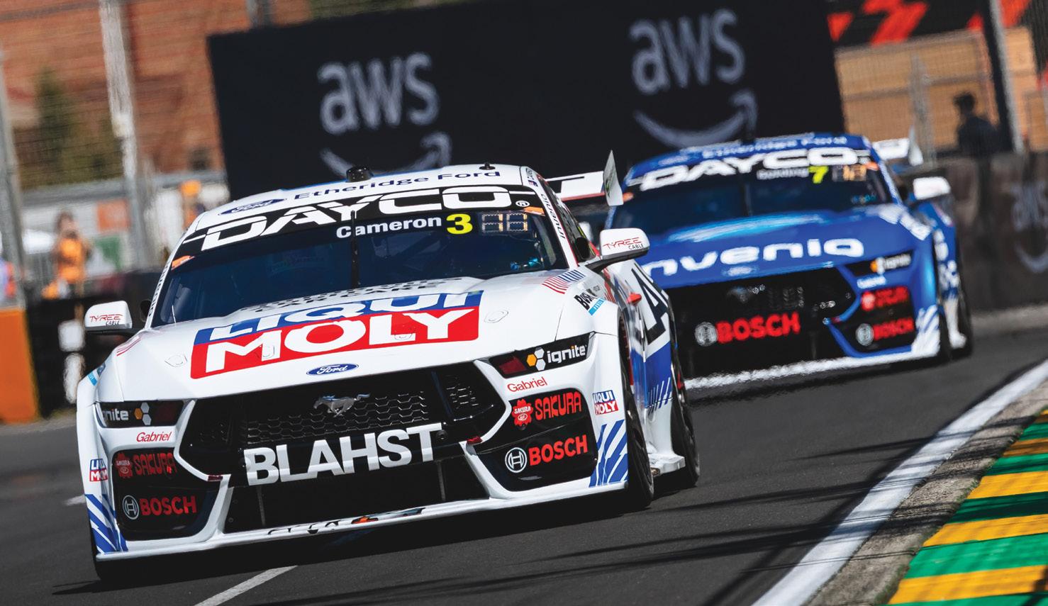
Dayco will be making four trade-account customers and their partners the company’s VIP Guests at one of the nation’s most spectacular motorsport events, the 2026 Boost Mobile Gold Coast 500 held on the streets of Surfers Paradise from October 23 to 25.
Winners will travel to the GC500, enjoy corporate hospitality at the event and take part in Supercar and Porsche Carrera Cup team pit tours at this exciting seaside event.

This competition is open to Australian tradeaccount customers who gain an entry for the purchase of Dayco, Powerbond or Nuline engine components to the value of $500 or more from any Dayco distributor in a single transaction from now until October 1, 2026.
Entering is simple. Trade customers can scan the competition QR code, add an image of their Dayco, Powerbond or Nuline parts-purchase invoice and tell Dayco in 25 words or less why they want to win a trip to the GC500 as the VIP guests of Dayco Australia.
Alternatively, Dayco trade customers can send their proof of purchase and 25 words or less to compete in this game-of-skill competition to Dayco.GC500@dayco.com Multiple entries are permitted when they
are accompanied by separate proof-ofpurchase invoices for $500 or more of any Dayco, Powerbond or Nuline components until the closing date of October 1, 2026.
‘We want to give our trade customers the opportunity to win a real money-can’tbuy motor-racing event experience,’ said Dayco Australia General Manager Geoff Upton. ‘The four lucky winners and their partners will travel to one of Australia’s most spectacular Supercar events and get the VIP treatment throughout.
‘They will also meet our Dayco-sponsored drivers and teams while also having a welldeserved break in Surfers Paradise. Be sure to get your entries in soon.’
• For full terms and conditions, go to bit.ly/3QFkul3

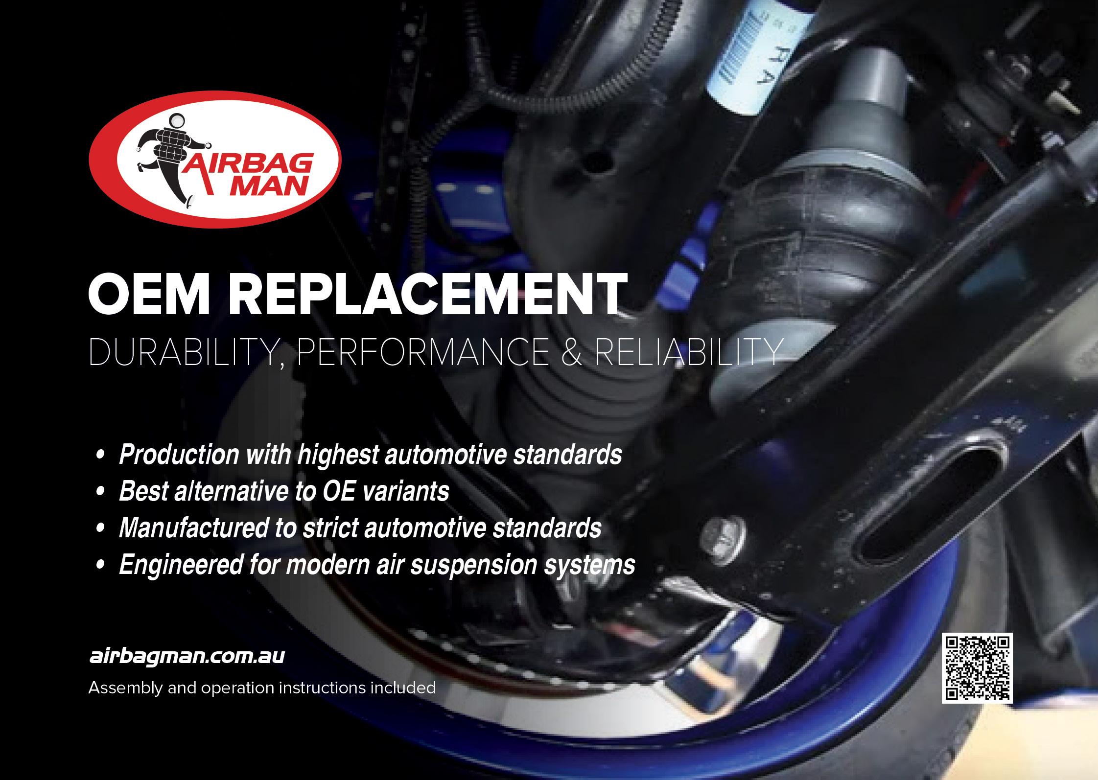
European luxury vehicles continue to advance their air-suspension systems and manufacturers such as BMW, Mercedes-Benz and Land Rover have helped redefine expectations for ride comfort, load levelling, handling and vehicle integration.
Modern air-suspension systems are no longer standalone mechanical arrangements. They rely on precise interaction between compressors, valve blocks, air springs, sensors and control modules. As these systems become increasingly sophisticated, the quality and precision of replacement components play an ever more critical role in maintaining system performance, ride quality and long-term reliability.
Airbag Man offers a broad range of OEM and aftermarket replacement air-suspension components, including air struts, air springs, compressors and valve blocks for European vehicles from Land Rover, BMW, MercedesBenz, Audi and Bentley.
Airbag Man’s range of OE-equivalent replacement components is designed to provide reliable fitment, compatibility and performance across modern air-suspension systems.
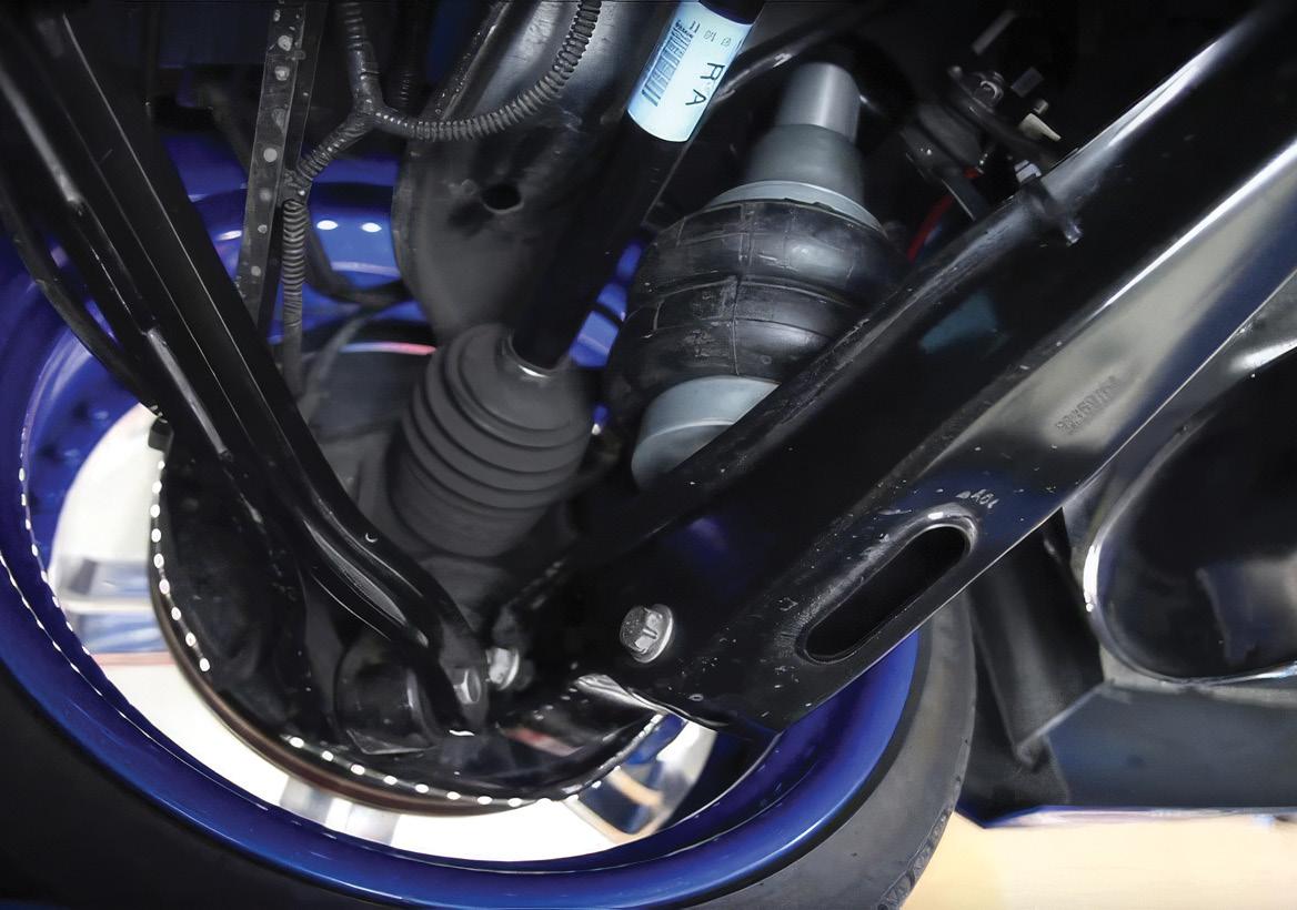
Precision fitment is especially important in air suspension. Vehicle manufacturers apply strict material specifications, dimensional tolerances and testing protocols to ensure components operate correctly within increasingly complex vehicle systems and even a slight deviation can affect rideheight calibration, handling, compressor workload or overall system performance.
OE-level engineering is particularly important because
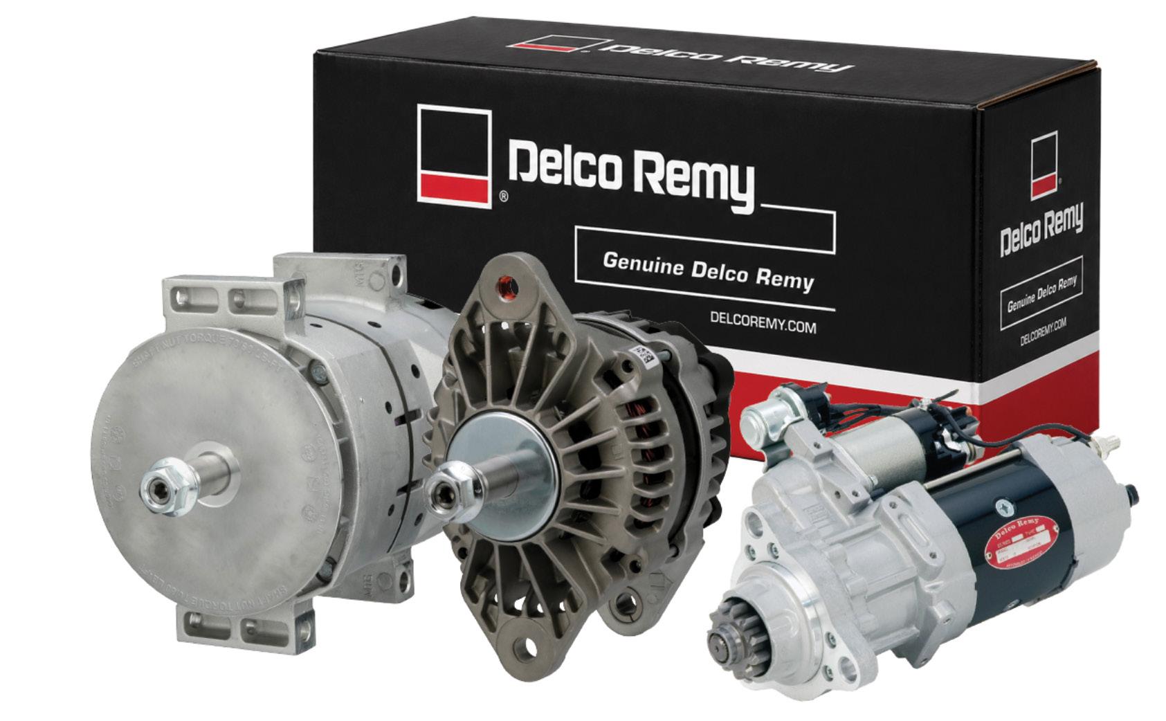
Adrad has expanded its heavy-duty electrical range with the release of Delco Remy starter motors and alternators for commercial on-highway, off-highway, agricultural, industrial and marine applications.
Delco Remy is a world-leading OE manufacturer of heavy-duty starter motors and alternators for trucks, buses and other commercial vehicles. With more than 130 years of experience, Delco Remy products have long been selected by vehicle manufacturers as original equipment and are a recognised choice among repairers.
Offering OE-quality, direct-fit replacement, the range includes products for both 12V and 24V applications. Each unit is engineered for dependable service in demanding operating conditions and is backed by a 12-month warranty.
Delco Remy heavy-duty starter motors are designed for demanding starting applications across a broad range of commercial vehicles and equipment. The range includes both gear-reduction and direct-drive designs, providing reliable performance, durability
and long service in harsh working environments.
Delco Remy heavy-duty alternators are developed for demanding charging applications in heavy vehicles and off-highway equipment. Brushed and brushless designs are available, with brushless units offering reduced wear, while both types are engineered to deliver strong output and long service life.

the mechanical, pneumatic and electronic parts of the system must operate together. Compressors, valve blocks, air springs and sensors all contribute to maintaining the intended vehicle ride height, comfort and stability. A component that does not perform as expected can place additional load on the rest of the system and affect how the vehicle responds.
Demand for OE-equivalent European suspension components continues to grow across luxury and mainstream vehicle platforms. For workshops and vehicle owners alike, selecting components engineered to meet original specifications remains an important factor in maintaining vehicle comfort, performance and long-term reliability.
Partner with Airbag Man to help your clients confidently conquer any load or terrain.
• Find out more at airbagman.com.au or call free on 1800 247 224
the Radshop or Natrad Trade websites. Parts can be searched by OE number, Delco Remy part number or competitor equivalent part number.
The range covers popular Australian, North American, European and Japanese vehicles, including trucks, buses, off-highway vehicles, agricultural equipment, stationary engines and marine applications. Repairers can identify the correct Delco Remy starter motor or alternator through
• Natrad Trade customers can visit NatradTrade.com.au or call 1800 628 723 to speak with their local branch or sales representative. Adrad customers can visit Radshop.com.au or call 1800 882 043 for assistance.

Century Batteries has extended its partnership with the Australian Road Safety Foundation (ARSF), expanding a collaboration focused on safer driving, vehicle maintenance and reducing road trauma across Australia.
After ARSF served as the official Charity Partner of the 2025 Century Batteries Ipswich Super 440, the partnership will grow during 2026. Century Batteries will support several national ARSF campaigns, including Fatality Free Friday, Rural Road Safety Month, Work Related Road Safety Month and Christmas road-safety initiatives.
Century Batteries Marketing Manager Automotive Andrew Bottoms said the partnership reflected the company’s longstanding commitment to road safety, community wellbeing and Australian motorists.
‘Safe driving behaviours and safe, wellmaintained vehicles go hand in hand,’ said Bottoms. ‘As a trusted supplier to motorists across Australia, we recognise we have a role to play in helping drivers understand the importance of vehicle maintenance and preparation and how these simple actions can contribute to safer journeys.’
The two organisations will develop
educational content showing the link between vehicle condition and road safety. This will include information on battery health and its role in supporting modern electrical and safety systems, including airbags, emergency-braking technology, telematics and hazard lighting.
They will also collaborate on social media, video and public-awareness activities encouraging motorists to complete regular vehicle checks, particularly before longdistance travel, holiday periods and seasonal driving conditions.
The partnership will continue at major motorsport and automotive events, including the Century Batteries Ipswich Super 440, where the organisations can engage directly with motorists, trade customers and vehicle enthusiasts.
ARSF General Manager Donna Caley said the partnership would help strengthen roadsafety messaging through one of Australia’s most recognised automotive brands.
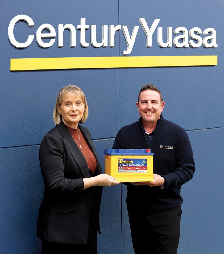
‘Together, we can continue to reach a broad audience of motorists with important roadsafety messages while highlighting the role that vehicle maintenance and preparation play in reducing risk on our roads,’ said Caley.
Throughout 2026, the partnership will deliver co-branded educational material, seasonal safety campaigns and communityengagement initiatives aimed at supporting safer driving and better vehicle maintenance.
• To find out more about Century Batteries extensive range of products or understand how your business can benefit from becoming a stockist, contact Century Yuasa on 1300 362 287

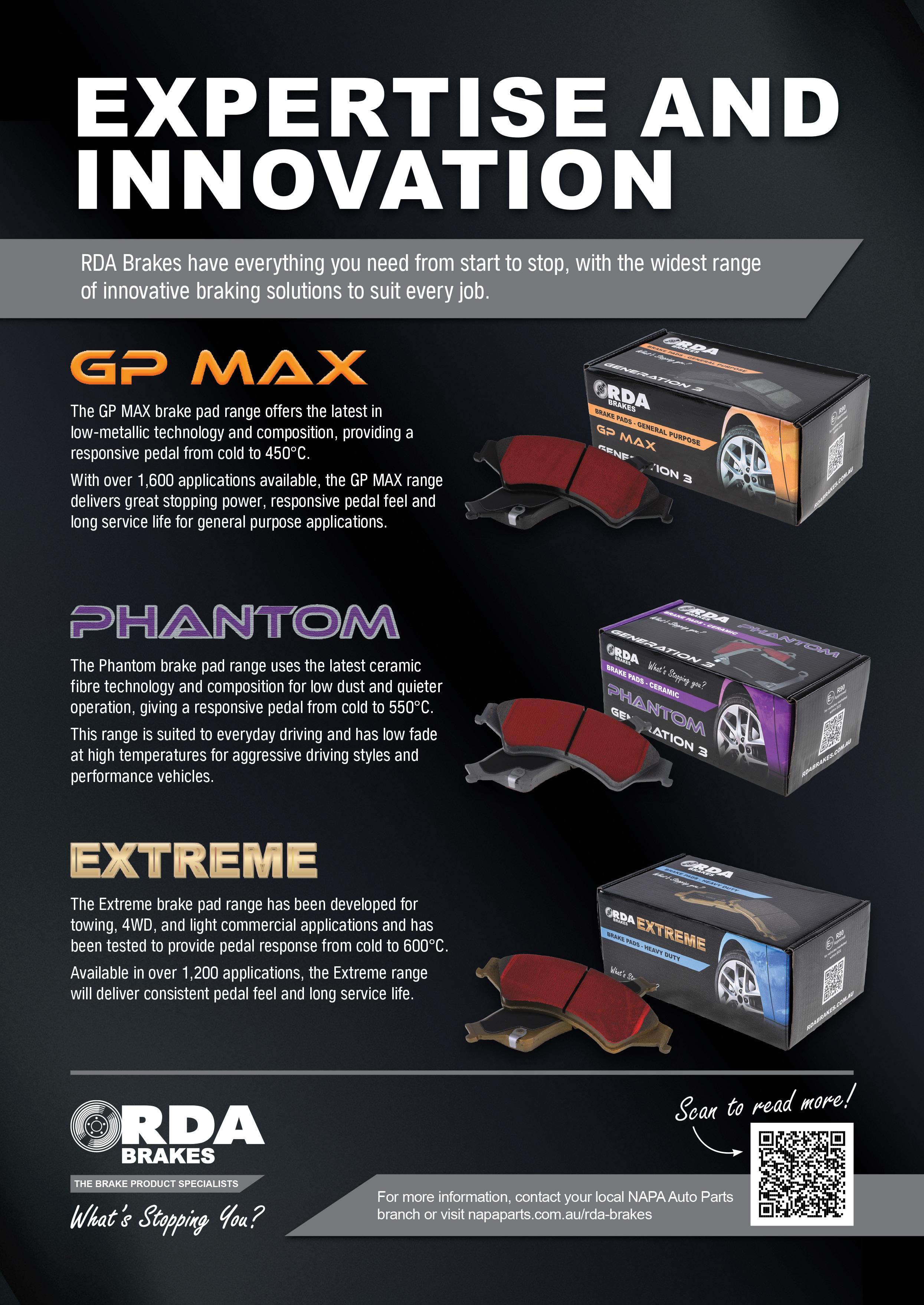
The RDA range of brake rotors, pads, drums and shoes is one of Australia’s largest, covering applications from everyday passenger vehicles through to light-commercial vehicles.
This breadth gives workshops the flexibility to select products that suit the vehicle and how it is used rather than relying on a single option for every customer.
RDA’s three-tier brake-pad range accommodates different vehicle types and driving styles, with options ranging from general replacement and everyday performance to products developed for light-commercial use. All RDA brake pads are backed by an 18-month/30,000km warranty.
The range also includes standard replacement rotors incorporating features commonly found in OE rotors. RDA standard replacement rotors are finished with the brand’s Gen 3 Anti-Rust Coating, formulated to increase resistance to surface rust on non-braking areas and help maintain a cleaner appearance after installation. Complementing the standard rotor range is a wide selection of slotted and dimpled rotors developed for Australian driving conditions. The directional slotting is designed to help manage outgassing from the brake pad material and reduce the conditions that contribute to brake fade, supporting consistent braking performance
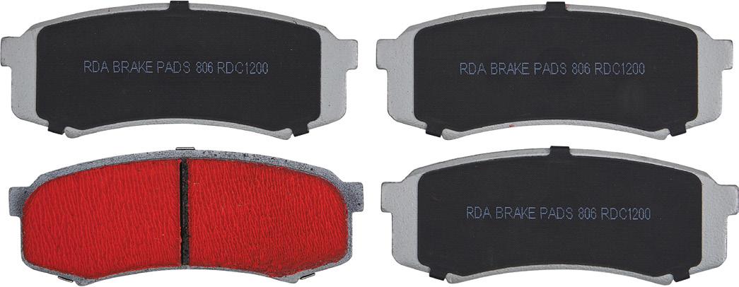
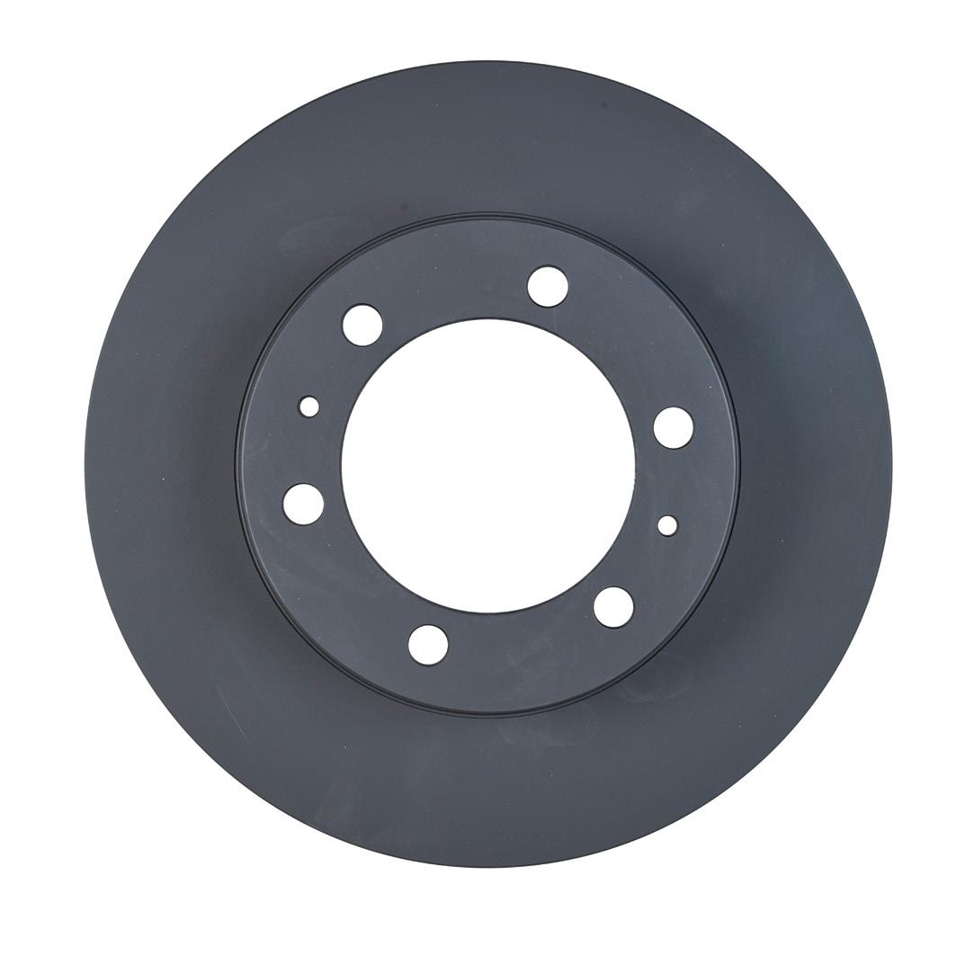
during demanding All RDA covered or 20,000 RDA’s light-commercial applications. Depending on the application, the drums may also incorporate features commonly found in OE assemblies, including bearings and anti-lock braking system (ABS) rings.
The RDA brake-shoe range has been specially formulated to deliver low noise, low dust and strong stopping performance. RDA also carries a range of Banksia handbrake bands containing the minor hardware required for faster, more convenient fitment. Together, the range gives workshops access to the main components required for a wide variety of brake repairs.
The full range of RDA Brakes products is available from NAPA Australia and New Zealand. RDA Slotted and Dimpled Rotors are also available nationwide from Repco.
• FInd out more at napaparts.com.au or repco.com.au

Customer complaint
The supplemental restraint system (SRS) or airbag warning light was on.
Problem summary
Confirmed the SRS warning light was on. The clock spring on the vehicle had previously been replaced to fix a separate fault.
Diagnostic sequence
Checked the battery voltage and it was OK – 12.6V.
Checked the charge rate and it was also OK – 13.9V.
Scanned the vehicle for diagnostic trouble codes (DTCs) and found the following:
• B1610 – Passenger pretensioner squib open
Visually inspected the passenger pretensioner squib (PPS, passenger seatbelt reel) – it was connected securely, with the shorting-bar tab latched.
Disconnected the PPS and fitted an SRS emulator (resistor) but the DTC remained. Set the emulator to two ohms (Ω) – the DTC remained.
Set the emulator to 1Ω – the DTC was now history and could be cleared.
Set the emulator to 0Ω/shorted – the DTC did not return and there were no fault codes (pic 1).
Disconnected the emulator – B1610 returned.
Disconnected the SRS module with the ignition off and the SRS fuse removed.

Measured continuity from pins 27 + 28 at the SRS module (harness side) to the PPS connector – open loop (OL).
Connected the SRS emulator set to 3Ω and tested the continuity – 6.5Ω.
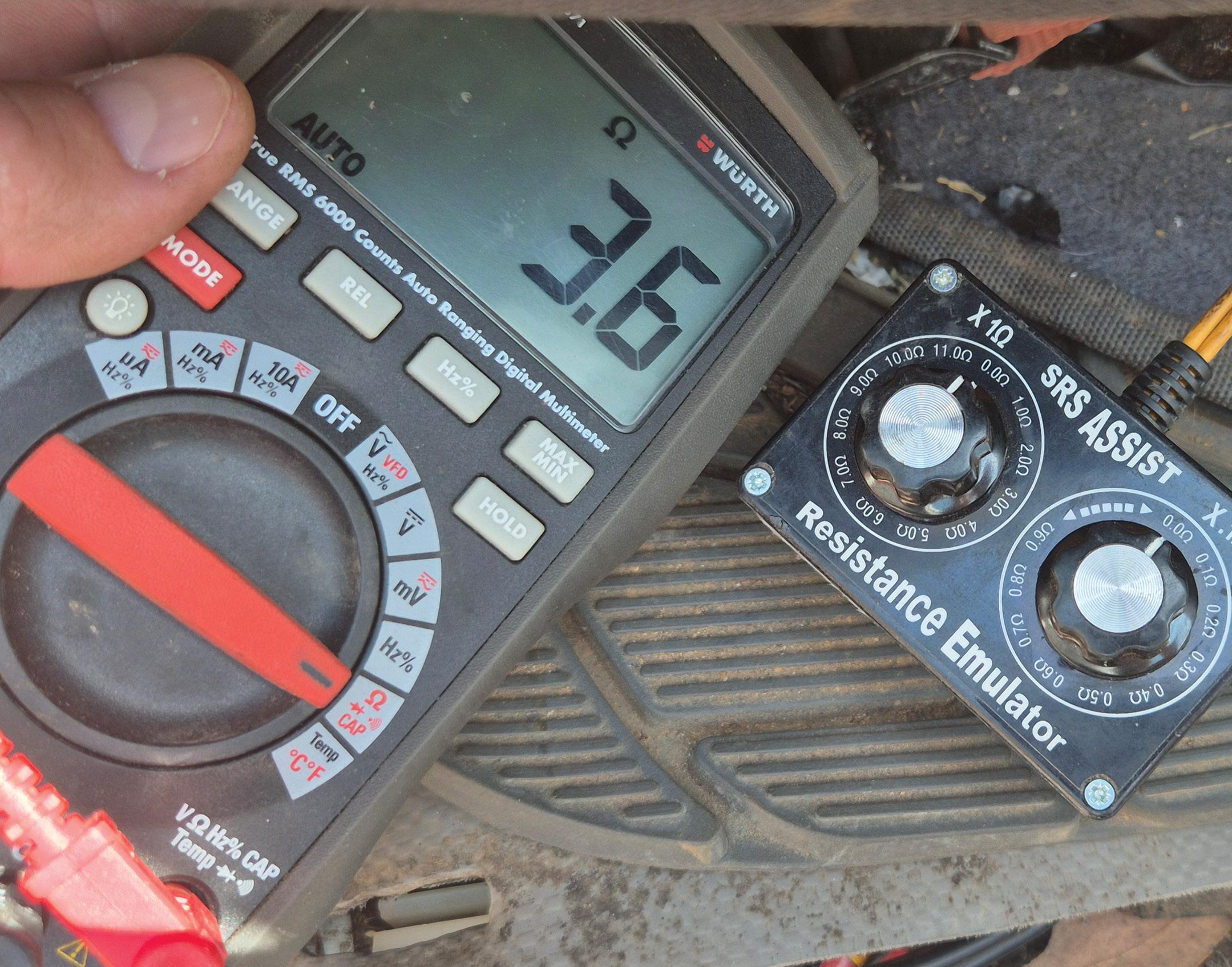
Shorted the PPS connector pins (set emulator to 0Ω) and tested the continuity –3.5Ω (pic 2).
Checked the resistance of the red/blue circuit from the SRS module to the PPS –3.3Ω.
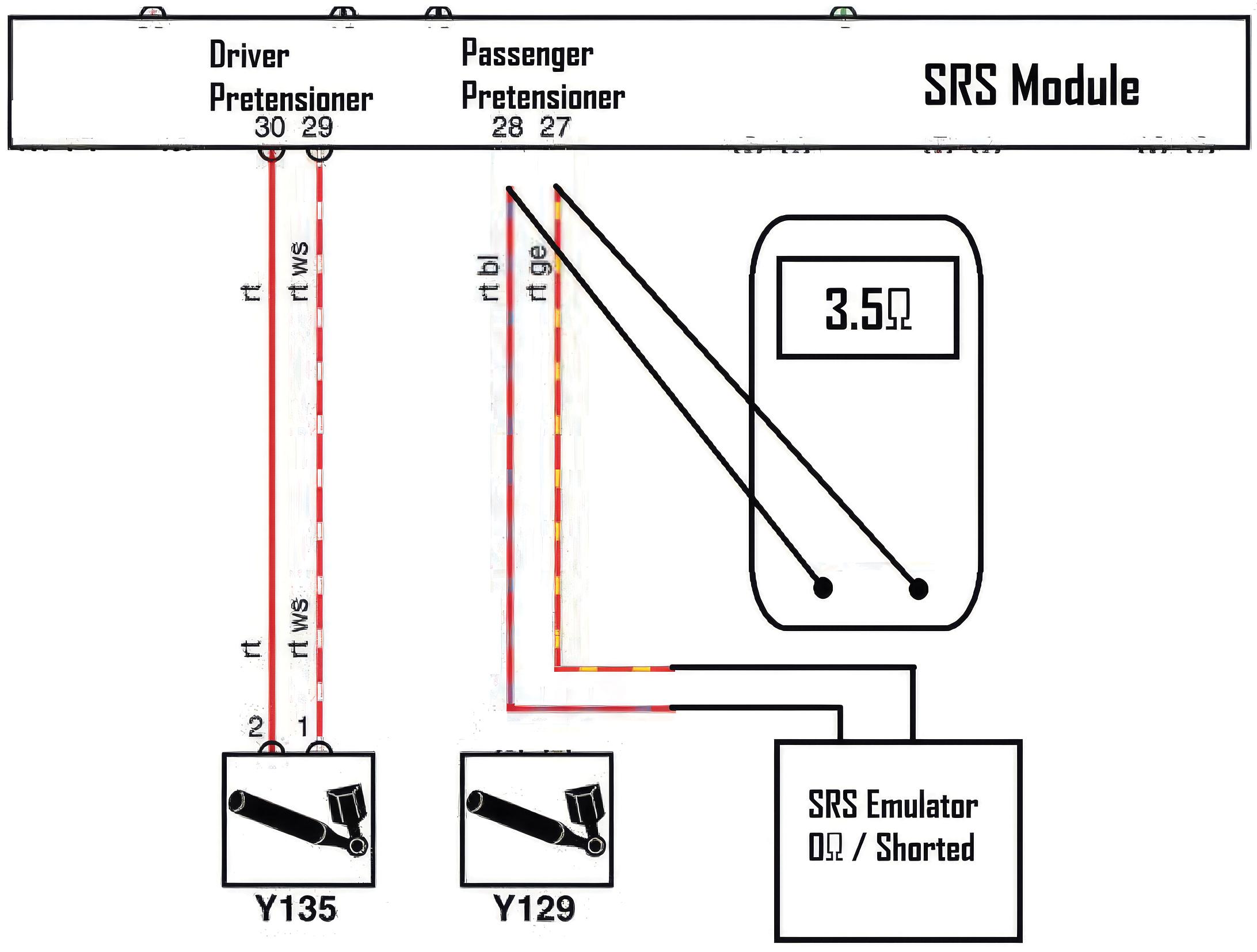
The passenger pretensioner red/blue circuit had a high resistance, causing the not-faulty passenger pretensioner squib circuit to set a DTC as the module sees a total of the two resistances (i.e. 3Ω at the passenger pretensioner, 3.5Ω in the circuit = 6.5Ω, over the threshold for OL).
Fault solution
Recommended replacing the interior floor harness.
Recommended time
Diagnostic time was one hour, taking into account preparation and research.
Repair time n/a.
There is a Hotline Fix related to the floor harness in these MN Tritons, ML52-003MN-PB52-001. I found this one very interesting, specifically that the resistance in the harness was the exact correct resistance to match the pretensioner – so if you just short the wires together the fault stays away (not what I did).
Repair Solution by TaT Tech Team member Gary O’Riain.
The vehicle would not change gears and various warning lights were illuminated.
Problem summary
Inspected the vehicle and the check-engine light (CEL) and traction-control warning lights were on.
When shifting from park to reverse/neutral, the gear changes were very harsh and clunky. Once in drive it would not change gears at all, feeling stuck in third.
Had the vehicle towed to an automatictransmission repairer, where the transmission-lead frame – housing the input/ output-speed sensors, transmission-fluid temperature sensor, etc – was replaced but according to the workshop this did not solve the issue.
Checked the battery voltage and it was OK – 12.5V.
Checked the charge rate – it was also OK, 14.2V.
Scanned the vehicle for diagnostic trouble codes (DTCs) and found:
Powertrain control module (PCM)
• P0674 – Cylinder 4 glow plug
• P0113 – Intake air temperature sensor 1 (IAT1) circuit high
• P0700 – Transmission control system (MIL request)
Anti-lock braking system (ABS)
• U0401 – Invalid data received from the PCM
Transmission control module (TCM)
• U0401 – Invalid data received from the PCM
Monitored live data in the PCM and found

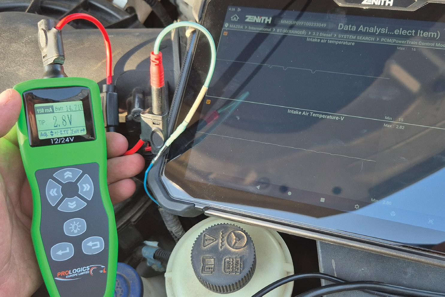
the exhaust-gas recirculation (EGR) opening percentage was always 15 per cent and the exhaust-temperature sensors were always 0ºC, which made me suspect the car had an EGR delete/tune.
Monitored the mass air flow (MAF) sensor, manifold absolute pressure (MAP) sensor, fuel-rail pressure (FRP) sensor, etc.
Found the intake-air temperature (IAT) was minus 40°C and did not change. In this vehicle the IAT1 is integrated with the MAF sensor.
Checked the MAF sensor circuits and they were OK – 12V supply plus ground (loadtested with test light).
Checked IAT sensor voltage and it was faulty – 5V when it should have been between 0.5V and 4.5V depending on temperature.
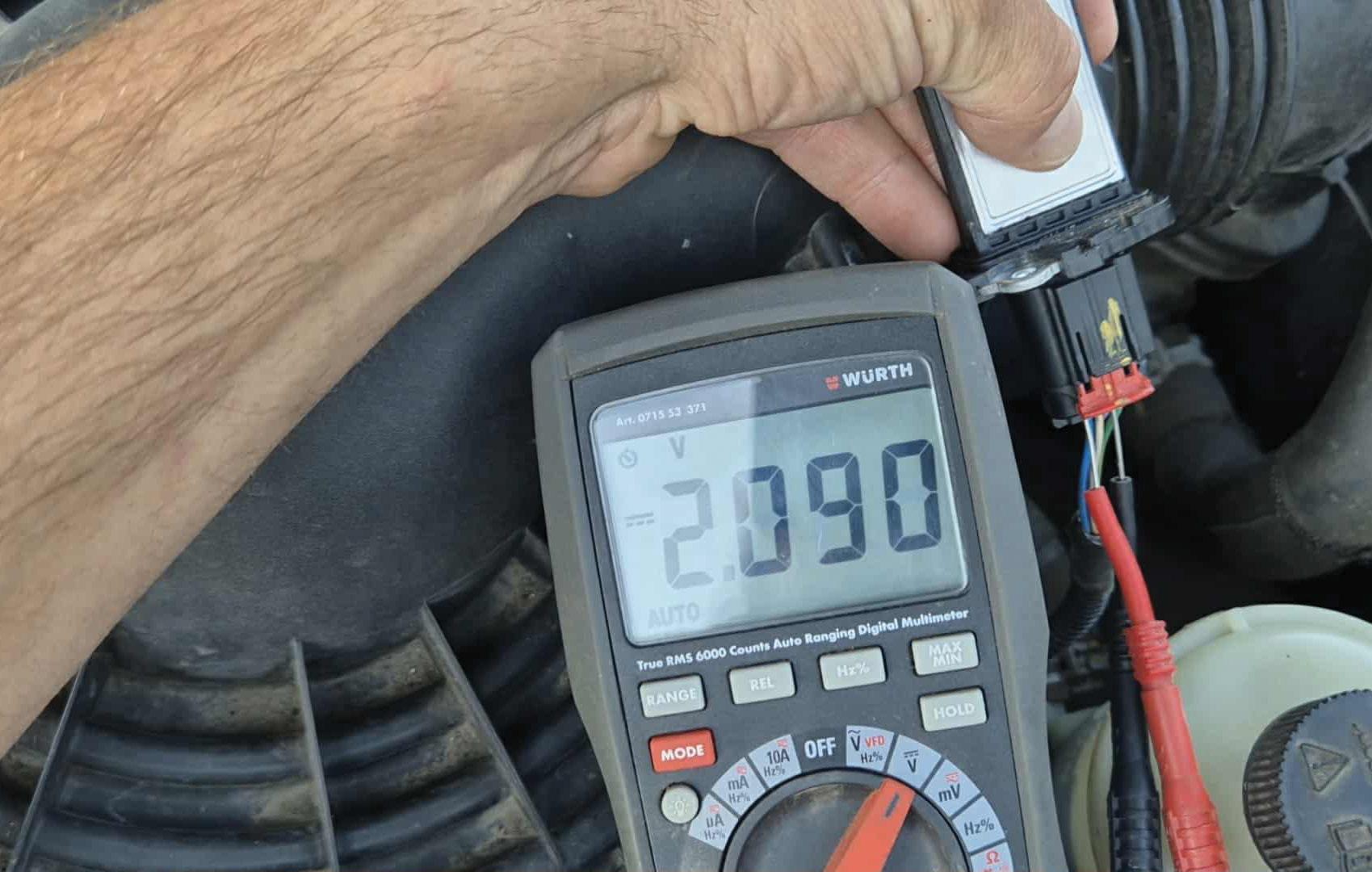
De-pinned the IAT1 5V circuit and varied the voltage to test the circuit to the PCM and it was OK – the displayed IAT1 parameter ID (PID) did change correctly.
Set the IAT to 20°C, cleared the DTCs and carried out a test drive (pic 1) and the vehicle was OK – it was now changing gears normally and there were no warning lights.
Fault description
Refitted the IAT1 pin to the MAF and the fault returned immediately with the same DTCs and symptoms.
Removed the MAF sensor, flexed the circuit and the IAT-sensor voltage changed erratically (pic 2).
Fault solution
Recommended the replacement of the MAF sensor.
The workshop later replaced the MAF sensor and confirmed the concern was gone – no more faults.
Recommended time
Diagnostic time was 30 minutes, taking into account preparation and research.
Repair time n/a.
This was a weird one as I have driven these cars with the MAF disconnected without these symptoms.
I’m guessing with the MAF disconnected the car completely ignores MAF and IAT but with the MAF connected the PCM is confused that some data is true and some is false, so it puts the car into limp mode.
Repair Solution by TaT Tech Team member Gary O’Riain.
The customer came in with a printout of a previous scan with many codes. Many related to communication or voltage faults in seemingly unrelated systems. His actual complaint was the remote locking did not work after about a minute of switching off and the interior lights were not working.
Rescanned the vehicle and performed a clear and rescan. Most codes returned.
However, while the scan was successful, the vehicle communication interface (VCI) switched off after the ignition had been off for a minute or two. Big clue.
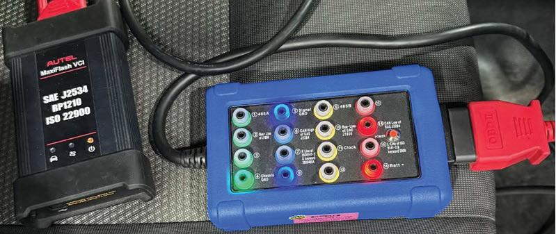
We have a little OBS breakout box which is fairly handy, so we plugged it in.
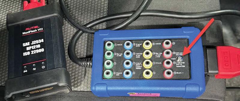
Pin 16, which should have battery voltage at all times, was only live while the ignition was on (pic 1), then for about a minute before it went dead (pic 2).
Traced the circuits back and found the fuse that powers the on-board diagnostics (OBD) port was not live and neither were the two interior-light fuses.
Powered up the interior-light circuit externally as a safe place to inject power and this resolved the issues. The locks and lights worked and pin 16 stayed live. Used a diagram to follow power back to the engine-bay fuse box and found no power to the main cable, the smaller of the three lugs (pic 3) which supplies

the internal fuse boxes. Bypassed here temporarily for testing (pic 4) and all was good.
Opened up the fuse box as everything is accessible from underneath and confirmed a failed fuse box, which is apparently pretty common.
Then ran a permanent external bypass via a fuse, which solved the fault.
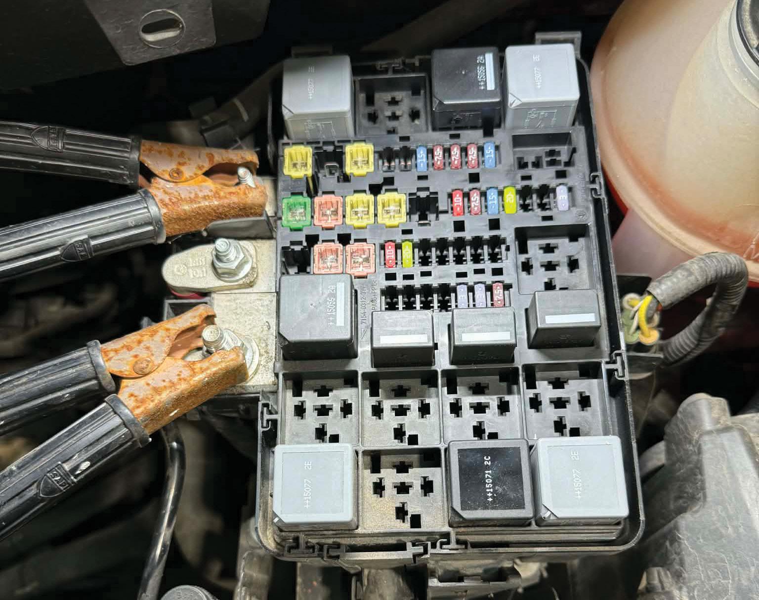
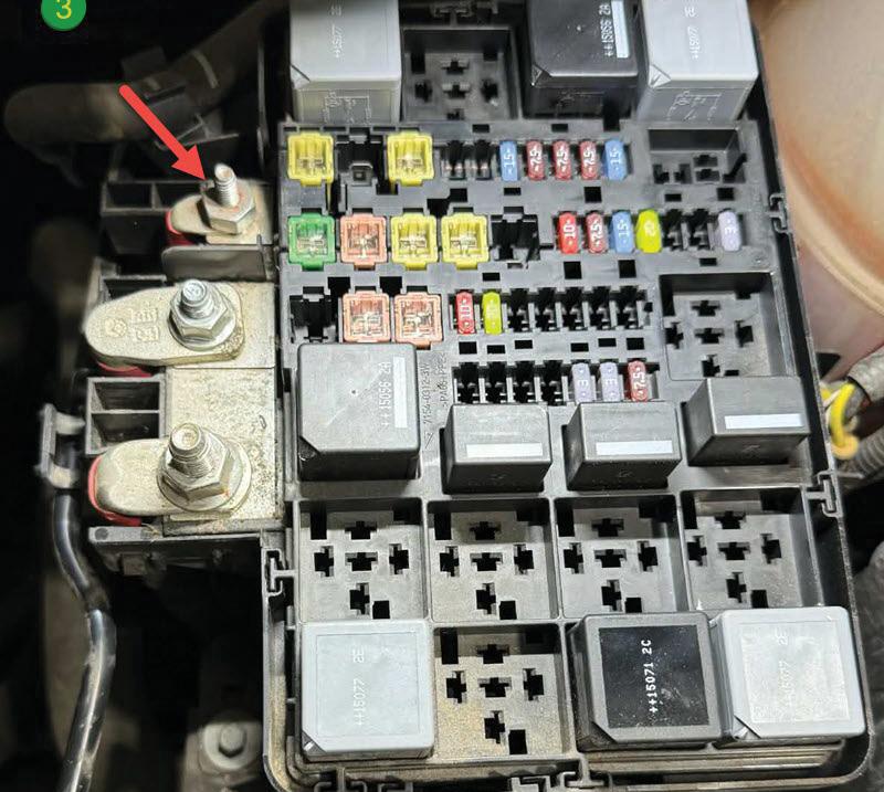
The engine-bay fuse box had failed.
Fitted a permanent fused bypass externally to the fuse box for the failed circuit.
Diagnostic time was two hours, taking into account preparation and research.
Repair time was one hour, taking into account the location of parts and carrying out the repair to a tested outcome.
Repair Solution by TaT member Carlton Quay.
complaint
Warning lights on the dash.
Problem summary
Verified the owner’s concern. There were several warning lights illuminated on the dashboard, including those for the anti-lock braking system (ABS), stability control and lane-departure warnings, etc.
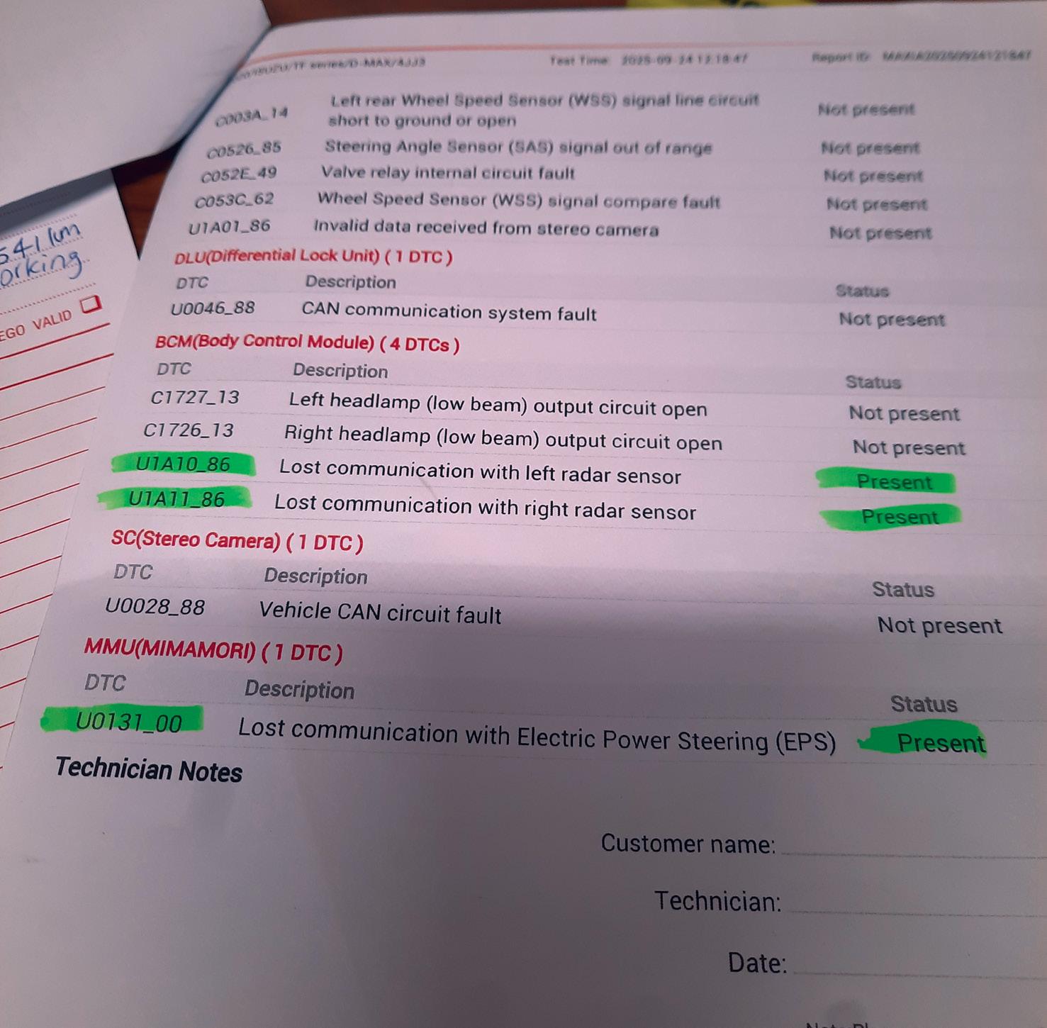
Started with the usual diagnostic tests first (battery test, charging-system test and lights test) before performing a full vehicle electronic scan, which brought up the following codes:
Body control module (BCM)
• U1A10_86 – Lost communication with left radar sensor
• U1A11_86 – Lost communication with right radar sensor
Memory management unit (MMU)
• U0131_00 – Lost communication with EPS.
Was unable to communicate with either rear radar sensor or the electric power steering (EPS) module via the scan tool (pic 1), so obtained a wiring diagram via the Isuzu portal and researched the communication networks.
Then started testing the circuits to the EPS module and found the controller area network (CAN bus) low circuit looked abnormal.
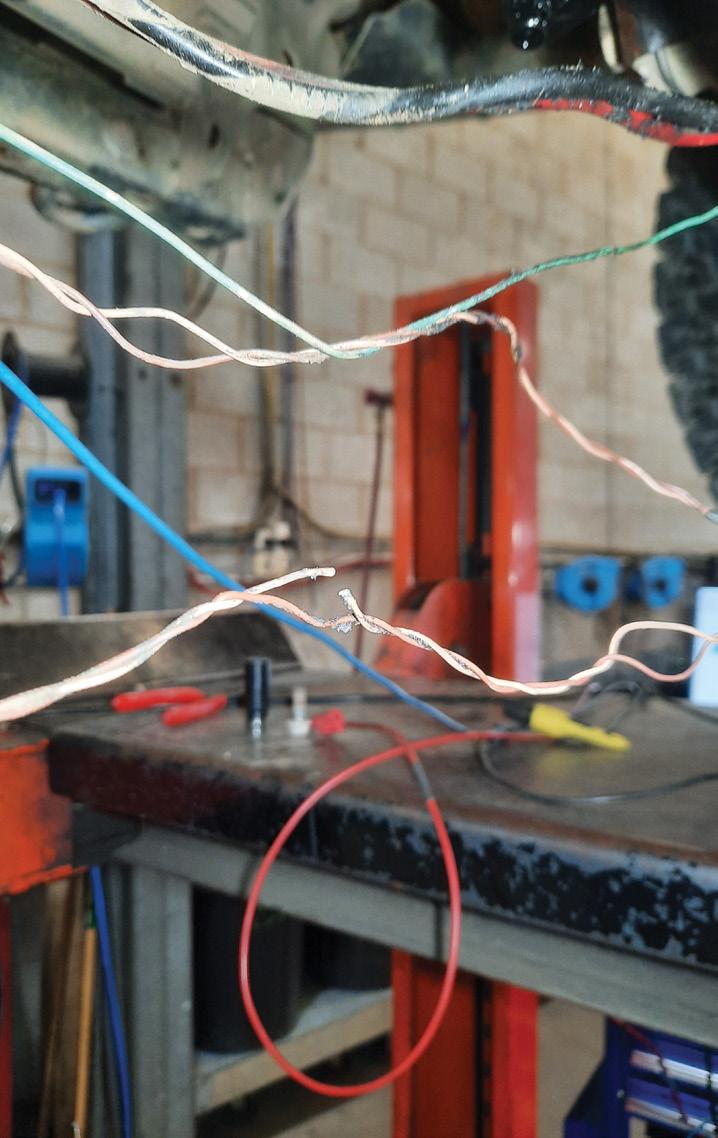
Traced and located a broken CAN wire in the wiring harness around the front of the steering rack (pic 2 and 3).
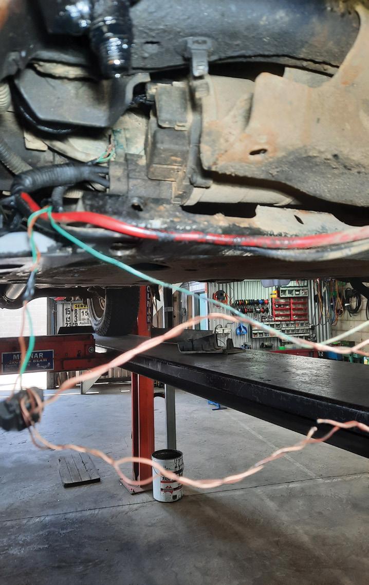

There was an open circuit in the CAN lowsignal wire going to the EPS module.
As it turned out, there was a CAN junction connector in this part of the harness too, so
the open wire was also causing the loss of communication to both rear radar sensors.
Repaired the wiring harness and secured it correctly.
Reassembled all components, erased the fault codes and retested operation to verify the repairs.
Diagnostic time was four hours, taking into account preparation and research.
Repair time was two hours, taking into account the location of the damaged wiring and carrying out the repair to a tested outcome.
This was a farm vehicle and we feel this wiring-harness area is susceptible to damage from impact as there were large clumps of mud around the components.
Repair Solution by TaT Tech Team member Marty Hosie.


When service, repair and potential electrical problems all come together: The importance of thorough inspections and checks while servicing modern vehicles
The importance of a proper service is frequently downgraded by those not in the know.
The conversation typically goes, ‘Oh, it just needs a service’. A lot of customers think that service not only fixes everything but means there is an unconditional warranty for the next 24 months.
However, we as professional technicians can still sell our worth and avoid unnecessary comebacks or complaints.
If you haven’t already, implement a strong and thorough service inspection checklist. List all tasks performed on your invoice and show your worth and any value-adds (i.e. undercar and underbonnet inspections, along with light checks, throttle-body cleaning, pollen-filter inspections, wiperblade replacement, brake checks and measurements) so the customer knows their money was well spent, has confidence their car will be reliable in the future and that you were the right workshop for the job.
Here are two case studies where, during service and inspection, problems were found and how they were dealt with.
Case study 1
Mazda 3, BL10, 11/2011, 2.0-litre LF engine, 121,000km on the clock
The background
One of my regular customers had purchased the above vehicle within the last
few months. He’d booked the car in for service and asked me to inspect the vehicle to make sure it was safe and had were no underlying issues, etc.
This is a scenario to be wary of because this can sometimes mean the customer wants you to look into your crystal ball.
I put the vehicle through the usual highquality service-and-inspection process, which of course included a smart battery test and alternator test. It’s worth mentioning at this point I’d noticed a reasonably new battery had been installed in the vehicle.
The owner had already approved the price estimate and the job was nearing completion. However, as is my usual practice, I carried out a quality control (QC) inspection just before the bonnet was closed for the final time prior to the road testing and dataacquisition phase of the job.
The QC inspection delves under the bonnet and over the vehicle to ensure all items in the service list have been completed, including torquing wheel nuts, lubricating the door hinges, stamping the service book, attaching a service sticker, ensuring no tools have been left behind (if you’re that way inclined) and so on.
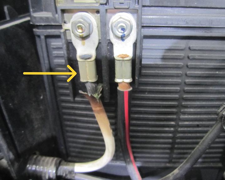
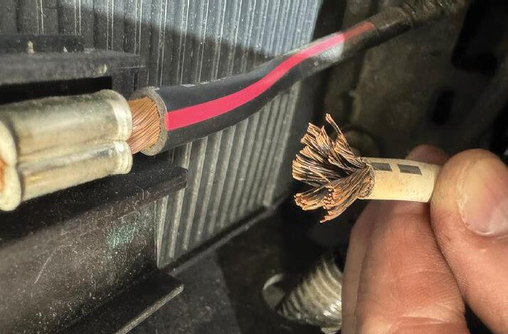
On this vehicle, I noticed one of the two lug connectors attached to the positive battery terminal was badly burnt (pic 1). This can be easily missed on a Mazda 3 because the lug terminals are located within the covered battery box, so they are somewhat hidden.
Immediately performed a voltage-drop test on the circuit that went between the burnt battery terminal lug and the B+ terminal on the back of the alternator. For those not familiar with voltage-drop testing, I recommend referring to the TaT website. Ask Tech Tina or click the ‘Diagnostic Programs’ button, then ‘Circuit Trainer’. When testing any electrical circuit, the test should be performed with the system loaded, meaning turning on all electrical accessories (i.e. headlights to high beam, heater fan and a/c on high, rear demister activated and so on).
Interestingly, during the load test – and with just the headlights on low beam only –
1 2
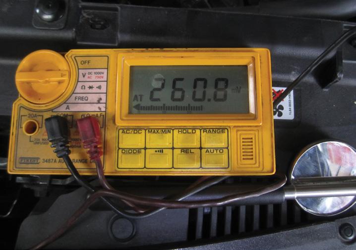
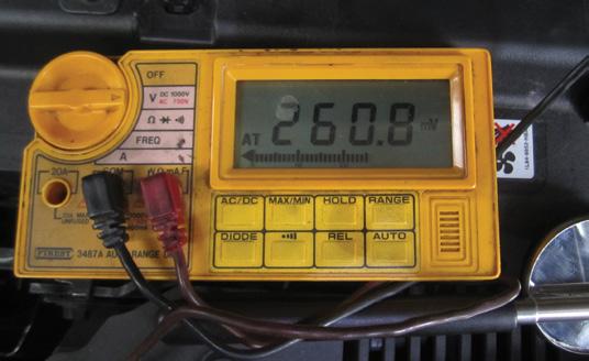
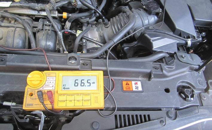
I noticed the voltage drop was 260.8 millivolts (mV, pic 2), which is close to the 300mV allowable limit.
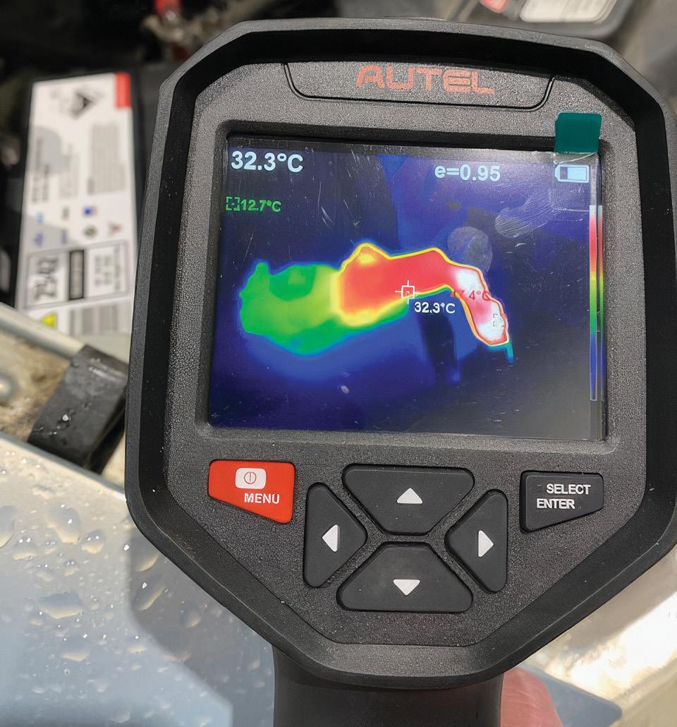
The lug terminal in question was not hot to touch. However, as soon as the system was loaded properly (i.e. more than just the headlights on low beam), the voltage drop increased dramatically and the lug terminal in question got extremely hot, to the point where I burnt my finger within five seconds. There was no need for a thermal-imaging camera analysis on this terminal. If you were to use one, pic 3 is something like what you’d expect to see. Note, this image is an example only.
This problem, left unchecked, would eventually end in a failure or fire, so I took some pictures and shared them with the owner, along with an explanation and a possible repair plan.
I also warned the owner that if the problem was left unchecked, it could create further problems down the track and shorten the life of some components in the electrical system, burn the alternator out or, in a worst-case scenario, become a fire risk. The owner agreed to the proposed repairs.
A closer examination showed the wire and lug terminal in question were part of the main wiring loom.
I cut off the burnt lug and stripped the wire back to crimp a new lug terminal on but the wire was corroded (pic 4), which was not a good situation. While being careful not to cut too much wire off, I cut the wire back a little further.
The wire was now better, if not perfect, but there was just enough wire to crimp a new lug on.
To make the repair better and the circuit stronger – and after discussing it with the owner – I added an extra circuit in parallel between the questionable lug and the alternator, an economical and reliable way to fix the issue.
I made up a jumper wire with the appropriate lugs attached to each end, added the new cable to the circuit and then routed and secured it correctly.
Retested the circuit fully loaded and got an awesome final reading of 66.5mV (pic 5), a good outcome to what could ended in an expensive future fault or breakdown.
Toyota Corolla, ZRE152, 02/2014, engine 2ZR-FE 1.8L and 160,000km on the clock
The background
The vehicle had been booked in for its 160,000km service. Importantly, as per Toyota’s service schedule, this is a major service and involves the replacement of the in-tank fuel filter replaced, which is quite an expensive job to perform.
This was a regular customer, so the job and price estimate had already been discussed and approved.
When taking on this particular service on 150 Series Corollas, I always perform the task of replacing the in-tank fuel filter last.
As always, I observed the fuel-tank gauge reading prior to stripping the vehicle down, noted it on the job card and took a digital photo.
After stripping the vehicle down and disconnecting numerous hoses and electrical connectors, it was time to loosen the fitting, or top retainer, that holds the fuel-tank module assembly in place. This is performed using special tools that have been shown in previous TaT articles.
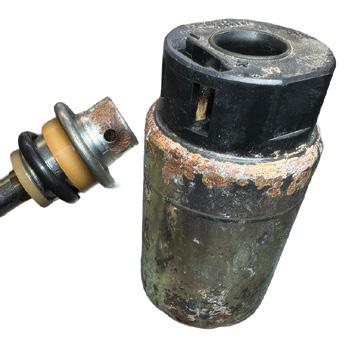
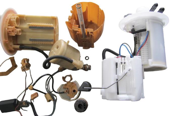
After removing the fuel-tank module assembly, I discovered a lot of rust on some of the components, particularly the fuel pump and pressure regulator (pic 6). On closer examination, I noticed the fuel-pump pigtail wire was badly corroded and had a burn mark due to excessive heat.
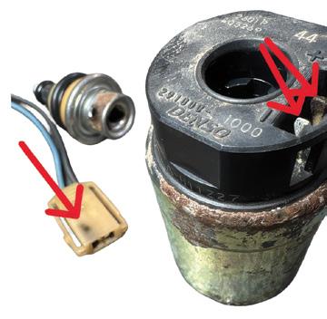
The fuel-pump terminals (i.e. positive and negative) were also badly corroded (pic 7). In fact, the positive terminal on the fuel pump was so badly corroded it was black. There was no way this was going to make good contact with the electrical terminal if put back into use.
Next came a visual inspection inside the fuel tank to check the fuel quality. There did not appear to be any signs of contamination or water in the fuel. I was thinking this vehicle may have had E10 fuel added to it at some stage.
repair
Sourcing parts currently can be a real problem and proved to be no different with this vehicle. Some individual parts were available and some weren’t. Some parts were expensive and others weren’t. This was a real conundrum.
What was readily available were cheaper aftermarket complete assemblies, something I’m not a big fan of as their quality can be lacking.
Searching a little deeper, I was able to find a genuine-quality complete tank module assembly from an aftermarket supplier at a reasonable cost, along with delivery in a timely manner.
I contacted the owner and told them about the problem. I asked about him possibly using E10 fuel. He told me he had not put E10 fuel in the vehicle.
I put the new repair scenario and estimate to the owner and he agreed to fitting the complete high-quality new fuel-pump module assembly (pic 8).
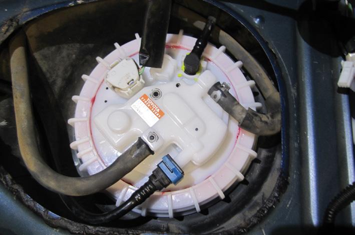
This was quickly sourced and fitted to the vehicle (pic 9) and the system was run and checked with no issues. I also performed a smoke test on the fuel-tank assembly to check for leaks.
Note, be careful when using the smoke machine in this way. You only want to use
low-pressure shop air, less than one or two psi, so you don’t damage the fuel system.
I then road-tested the vehicle with the scan tool attached, checking the fuel trims and oxygen (O2) sensor readings to ensure the vehicle’s fuel-delivery system was working correctly. All was in order, so the vehicle was returned to the owner.
Interesting fact. When the owner picked up the vehicle, he informed me his mum had been driving the vehicle and adding E10 fuel, which he did not previously know about. Lesson learnt.
Servicing modern vehicles requires high levels of skill and training.
It’s not just a matter of ‘a grease and oil change’, which is a term I heard a friend use just the other day. There is actually a lot involved with checks, special tools, training and procedures all required. And then there is the pressure of people always looking for someone to blame if something does go wrong.
My suggestion is this. Have high standards with your work and workmanship, don’t just be price-based. Use high-quality parts, acquire data with your scan tool on road tests and capture and store data and digital photos in a file under the customer’s name for future reference so – if a fault does occur – you can prove the vehicle was performing well and in good condition when it left your care and custody.
Having good service procedures results in customers’ cars running well, which saves them money, especially at the fuel bowser, minimises breakdowns and, importantly, creates less stress for you. And we all need that.
Happy diagnosing.


If you have recently purchased a digital storage oscilloscope (DSO), already own one or perhaps your scan tool includes built-in oscilloscope functionality, then welcome to the fascinating world of viewing live waveforms ‘dance’ before your eyes on the screen.
DSOs are capable of digitally capturing, storing and displaying electrical waveforms for further diagnostic analysis (see part 1, TaT issue 111).
In simple terms, a DSO acts as a signal processor between the automotive component and the display screen. Whether analysing controller area network (CAN bus) communication, crank-angle sensors, airflow meters or other signal-generating components, the DSO allows technicians to visually observe voltage changes over time.
Three common forms of DSOs
DSOs generally come in three configurations:
1. Standalone oscilloscopes
These are fully self-contained units incorporating waveform processing, capture, storage and screenshot capability within the one device (pic 1a).
2. PC-based oscilloscopes
These operate as an interface connected to a laptop or desktop computer, utilising the computer’s processing power and memory resources (pic 1b).
3. Scan tools with built-in oscilloscope functions
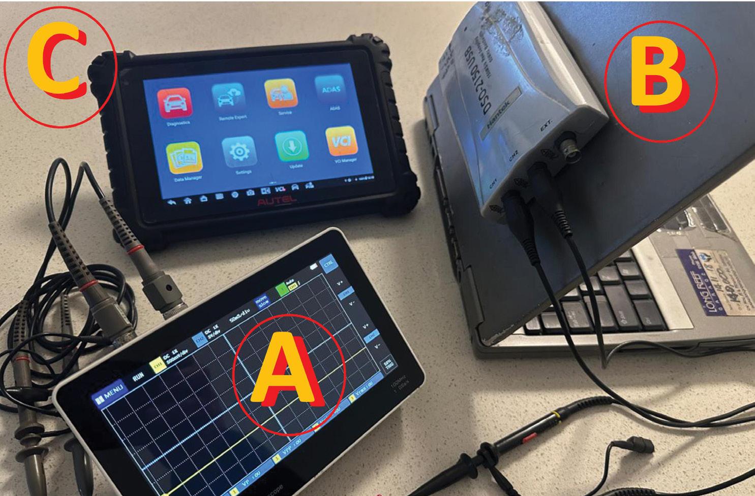
Many modern scan tools now incorporate advanced oscilloscope features directly within the scan tool itself (pic 1c).
Regardless of which type is chosen, virtually all DSOs will include:
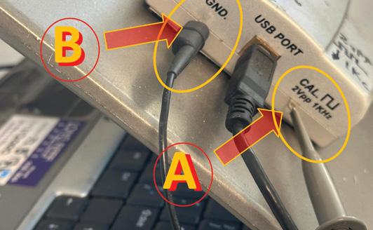
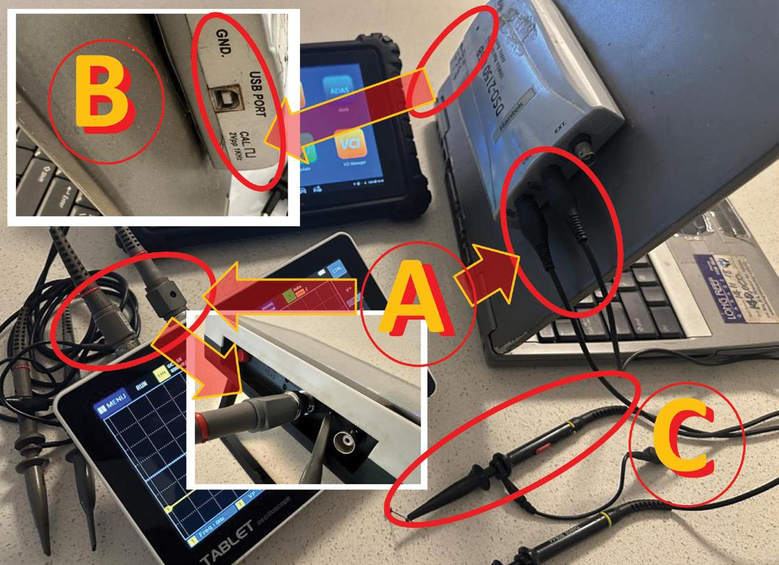
• BNC connector input terminals for shielded test leads and probes (pic 2a)
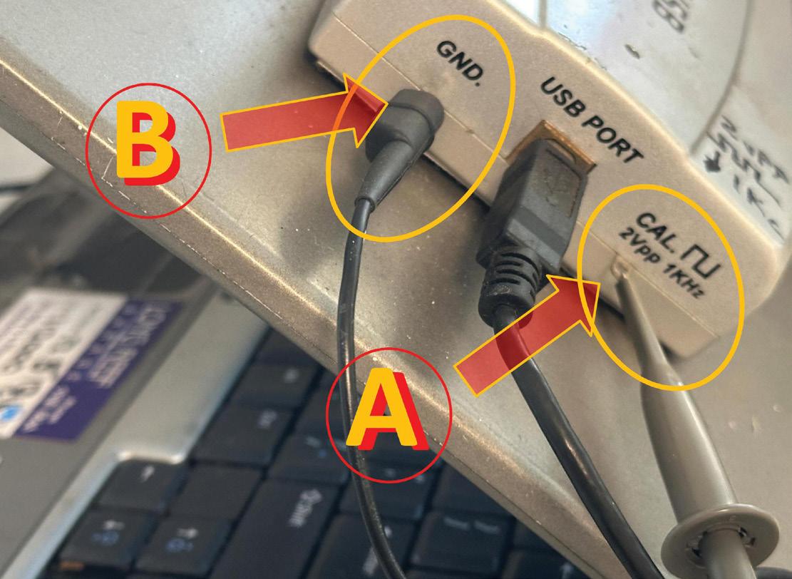
• A calibration port (pic 2b)
• Shielded probe leads, sometimes with attenuation controls (pic 2c)
But what do all these features actually mean?
How do we adjust the X and Y axes and how do we check the precision of these axes, the calibration of the X and Y scales?
Let us now walk the talk and begin getting acquainted with DSOs from the mechanic’s point of view (MPOV).
For the purposes of these articles, we have chosen a modestly priced stand-alone DSO with suitable specifications (see part 1, TaT issue 111, page 27).
However, even if your oscilloscope has lower specifications, such as reduced bandwidth or sampling rate, that is perfectly acceptable for most automotive diagnostic work.
While lower-specification DSOs may occasionally display slight aliasing or tapered square-wave edges at very high frequencies (see part 1, TaT issue 111, page 26, diagram 2), the fidelity of most automotive sensor signals will remain more than adequate for practical diagnosis.
Initial stepping stones to using a DSO
When first powering up a DSO, most users naturally expect to immediately see some form of ‘wiggly line’ or at least a straight trace across the screen.
After all, the oscilloscope is designed to display changing voltage over time, correct?
So naturally, many beginners touch the probe tip with their finger, hoping to act like an antenna and induce a signal on the screen, often with little success.
This is precisely why manufacturers provide a built-in calibration port.
The calibration reference signal generator
Almost all DSOs include a calibration output port generating a known reference signal, typically a 2V square wave at one kilohertz (kHz) or 1000 cycles per second (pic 3).
To begin:
• Connect the probe tip to the calibration output (pic 3a)
• Attach the ground clip (pic 3b)
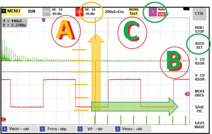
• Begin adjusting the Y axis (pic 4, yellow a)
• Then adjust the X axis (pic 4, green b)
• Then adjust the trigger settings (pic 4c).
Eventually, a waveform pattern will appear on the screen (pic 4, red square wave).
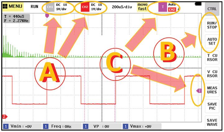
Initially, it does not matter whether the waveform appears stretched, compressed, large or small on the screen (pic 5, red square waveforms). The objective is simply to become familiar with manipulating the controls until a stable waveform becomes visible.
Understanding the X and Y axes
There are no rigid, hard-and-fast rules for setting the X and Y axis scales. And therein lies the beauty of the DSO.
The oscilloscope allows the technician to either:
• Stretch the waveform to closely inspect signal abnormalities and details (pic 5a)
• Compress the waveform to observe overall signal patterns (pic 5b), which can help identify any dropouts – more on that later (pic 5c)
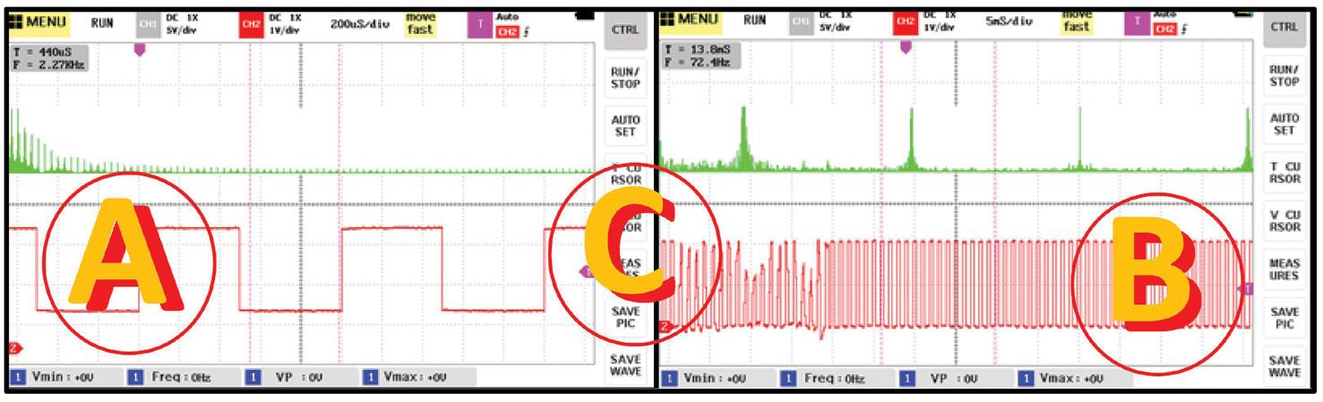
The Y axis: Voltage scale
The Y axis controls vertical voltage scaling (pic 6a).
Increasing or decreasing the voltage scale stretches or compresses the waveform vertically.
The X axis: Time base
The X axis controls the horizontal sweep rate/time (pic 6b).
Adjusting the X axis changes how fast or slow the waveform is displayed horizontally, effectively stretching or compressing the signal across the screen.
Which setting is correct?
That depends entirely on the purpose of the diagnosis. Sometimes overall signal shape is important; at other times, minute signal abnormalities become the focus.
Understanding trigger points
At times, you may connect the DSO and still see no waveform displayed. Often, this is due to the trigger level not being correctly set. The trigger point determines when the oscilloscope begins its sweep across the screen (pic 6c).
In other words, it establishes the reference point from which the waveform display starts. Once the trigger level is adjusted into the active region of the waveform, the display stabilises and the waveform becomes visible.
Free run vs triggered waveforms
When operating in free-run mode, the waveform may continuously drift sideways across the screen because the sweep is not synchronised to a fixed point on the signal (pic 6c).
However, when a trigger point is selected:
• The waveform becomes locked
• The display stabilises
• The signal consistently begins at the same voltage reference point
This creates a much easier waveform to analyse and interpret.
Getting acquainted with DSOs is actually far simpler than many technicians initially believe.
As a starting point:
• Connect the probe to the calibration port
• Adjust the X and Y-axis controls
• Establish a stable waveform
• Observe waveform height, width and frequency accuracy
Most importantly, begin experimenting and familiarising yourself with waveform behaviour.
In our next article, we will move into the real art of oscilloscope diagnostics: analysing and interpreting waveforms for practical automotive fault diagnosis.
Until the next publication
Locate the calibration port on your oscilloscope and generate a stable waveform. Then ask yourself:
• Does the Y axis correctly reflect the calibrated 2V output?
• Is the waveform stable and repeatable?
• And above all, does the X axis correctly display the 1kHz waveform frequency? If not, what method would you use to confirm it?
Practice these fundamentals and you will rapidly build confidence using DSOs in realworld automotive diagnostic stepping stones.
The authors would like to sincerely thank Jamie Andrews and Fuzail (‘Phil’) Shaik for their valuable assistance in assessing and discussing the operational characteristics and performance of the X and Y axes referenced throughout this article.
Their hands-on mechanical experience, practical fault-finding insight and technical input provided valuable real-world perspective during the evaluation process. Their continued support and professional contribution are sincerely appreciated. Please note: For publication purposes, screen captures (pic 4, 5 and 6) have been colour-inverted for ease of viewing, black on white rather than white on black (see DSO, pic 1a).
Modern vehicles continue to evolve and engines are working harder than ever, especially in 4WD and off-road applications.
Today’s increased accessory loads, tighter engine bays and higher operating temperatures place greater stress on critical components. When driving extends beyond sealed roads into remote and demanding terrain, drive-belt reliability becomes essential.
XtremeRunner Premium Belts are engineered to meet these challenges head-on. Developed by Gates as a premium solution, they are designed for drivers who expect dependable performance not only on highways but in harsh and unpredictable environments.
From rugged off-road tracks to extreme weather conditions, XtremeRunner is engineered to deliver confidence where failure is not an option. Manufactured with advanced rubber compounds and


high-strength tensile cords, these belts offer exceptional resistance to heat, abrasion, stretching and contamination.
Whether encountering mud, water crossings, dust or prolonged exposure to sand and debris, XtremeRunner is engineered to maintain optimal tension and efficient power transfer. This durability helps reduce the risk of slippage, cracking and premature wear, supporting long-term engine reliability.
For 4WDs operating under sustained load such as towing, recovery work or powering accessories including winches and dual-battery systems, XtremeRunner belts are built to handle the added demand. Their robust construction is designed to ensure consistent performance even when engines are pushed harder for longer periods.
Precision engineering also contributes to smoother operation by minimising vibration and noise, helping protect surrounding components and improve accessory-drive efficiency.
Gates XtremeRunner Premium Belts are engineered to deliver the durability and performance drivers depend on when it matters most, no matter how tough the conditions.
• Find out more at gatesaustralia.com.au



There are several options available to a customer when it comes to replacing a failed turbocharger.
The options listed here do generally apply to most popular makes and models but this article is specifically focused on Toyota HiLux models fitted with the 3.0-litre 1KDFTV ‘D4D’ common-rail turbodiesel engine.
The most common – and usually most expensive – option is an OEM replacement. This provides a turbocharger identical to the one being replaced. Fitting is straightforward because these units bolt into the same location and use the same fittings.
Garrett’s Red Boost program offers a complete drop-in turbocharger designed
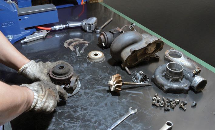
to replace the factory OEM unit at a significant cost saving. It provides OEM fitment and performance, backed by a Garrett 12-month warranty.
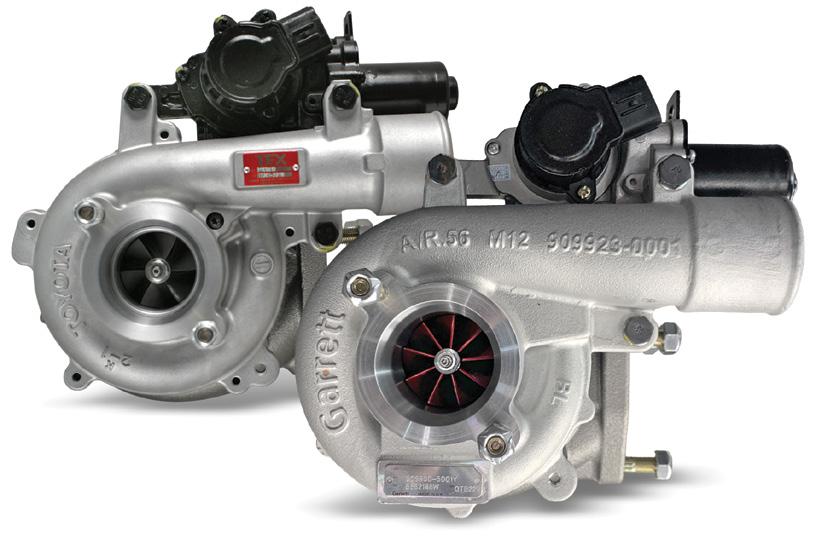
In many cases, the original turbo can be repaired or refurbished. Turbo-rebuild specialists such as Sydney-based GCG Turbos offer a Turbo Exchange (TEX) program, supplying a fully refurbished, balanced and flow-tested turbocharger at a fraction of the OEM replacement cost. Because these refurbished turbos use the original compressor and turbine housings, they are just as easy to install as the OEM units.
TEX turbos come complete with an actuator, gasket kit and 12-month warranty.
An upgraded turbo can provide extra power and torque, which may suit towing or offroad use. This option is worth considering if the owner is planning additional performance modifications or already has some fitted.
These units feature upgraded compressor and turbine wheels and offer considerable performance gains and cost only a fraction more than OEM replacement turbos.
HiLux Stage 1 and Stage 2 upgrades bolt directly into the factory location and require no additional fabrication. All HiLux 1KD-FTV turbo upgrades from GCG Turbos come complete with pre-calibrated actuators, gasket kits and a 12-month warranty.
A turbocharger is only one part of a larger system. Upgrading ancillary components such as the intercooler, air-intake piping and exhaust system can help achieve optimum engine performance.
GCG Turbos also recommends recalibrating the engine to keep exhaust-gas temperature (EGT) and lambda readings within safe limits.
• Find out more at gcg.com.au

The ONE Plus and ONE Pro combine intelligent software, advanced ECU programming and OE-level diagnostics to streamline repair workflows.
Every minute counts in a busy workshop. The faster a technician can identify a fault, flash an ECU and clear the bay, the more productive the business becomes.
TOPDON’s ONE Series includes two diagnostic solutions tailored to different workshop needs. ONE Plus is designed to provide advanced capabilities for everyday diagnostics and programming, while ONE Pro delivers expanded functionality for high-volume workshops and complex repair scenarios.
ONE Plus: Compact yet powerful solution
Featuring a responsive 10.1-inch display, ONE Plus supports four-system ECU programming for BMW and Volkswagen Group (VAG) vehicles, enabling ECU replacement, software updates and bug fixes. ECU coding and one-click customisation for more than 10 vehicle brands also allow technicians to unlock hidden functions and customise vehicle settings.
OE topology provides a clear visual map of communications between control modules, helping technicians pinpoint faults more efficiently. TOPDON’s TopFix AI
Assistant offers diagnostic guidance, repair explanations and technical documents, including wiring and component diagrams. Combined with bidirectional control, key programming and more than 50 Hot Service functions, ONE Plus provides a versatile solution for everyday professional repairs.
ONE Pro: Maximum capability for advanced diagnostics
For master technicians and high-throughput bays, ONE Pro adds a 12-inch screen, fullsystem ECU programming and advanced hardware expansion.
Its newly developed operating system retains vehicle information throughout the repair process, allowing technicians to switch between diagnostic and service functions without repeatedly re-identifying the vehicle. TOPDON says this streamlined workflow can improve repair efficiency by more than 50 per cent, helping technicians complete jobs with fewer interruptions.
ONE Pro also introduces TOPDON’s Live Data Fusion, allowing live data streams from different systems to be analysed together on a single interface for faster fault diagnosis. It also supports professional accessories including battery testers, oscilloscopes and
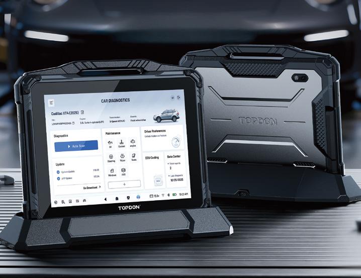
borescopes, creating a broader diagnostic ecosystem for complex troubleshooting.
Shared professional features across the ONE Series
Both ONE Plus and ONE Pro are built on the same professional foundation and designed to deliver the capabilities modern workshops expect.
From OE topology and the TopFix AI Assistant to ECU coding, bidirectional control, J2534 Pass-Thru programming and more than 50 Hot Service functions, both tools provide advanced workshop capability. Support for Diagnostics over Internet Protocol (DoIP) and CAN-FD protocols, alongside secure gateway access for Fiat Chrysler Automobiles (FCA), Renault and VAG SFD, prepares both tools for current vehicle technologies.
With the ONE Series, TOPDON aims to help technicians spend less time navigating software and more time solving problems, making repairs faster and workshop workflows more productive.
• Find out more at au.topdon.com


Geoff Mutton Business Resources
Every workshop owner understands time is money. We carefully monitor technician productivity, labour sales and workshop efficiency because we know every productive hour contributes directly to the bottom line.
But there is one area that quietly steals profitability every single day, and most workshops don’t even notice it –interruptions.
A technician stops what they’re doing to answer a question from reception.
Someone wants help diagnosing a fault. A customer walks into the workshop asking for ‘a quick look’. A parts supplier arrives. Someone can’t find the scan tool. The phone rings. Before long, the technician is trying to remember where they were up to.
None of these interruptions seem significant on their own. Most only take a minute or two. But let’s put some numbers around it.
Imagine a workshop with three technicians. If each technician experiences six interruptions during the day and each interruption averages just five minutes, that’s 30 minutes of lost productive time per technician.
Across three technicians that’s 90 minutes every day. Over a five-day week that’s 7.5 hours of lost productivity. Over a full working year of 45 weeks, that’s 337 hours, or the equivalent of nine full working weeks.
Now put a labour rate of $150 per hour against those lost hours. That’s about $50,000 worth of productive workshop time disappearing every year.
Of course, not every interruption is completely wasted time but the calculation demonstrates how small inefficiencies quickly become very expensive.
The real cost is often even higher because interruptions don’t just consume five minutes. They break concentration, increase mistakes and make technicians mentally restart complex jobs.
Here are some practical ways to reduce unnecessary interruptions in your workshop.
Modern diagnostics require concentration more than ever before. Technicians are analysing scan-tool data, following wiring diagrams, interpreting oscilloscope
patterns and researching technical information. Interrupting them halfway through often means they need several minutes just to regain their train of thought. Where possible, create uninterrupted diagnostic periods. Unless it’s genuinely urgent, allow technicians to complete a logical stage of the diagnosis before asking questions or redirecting their attention. You’ll often find the diagnosis is completed faster with fewer mistakes.
Almost every workshop experiences this. A customer drops in and says, ‘Can someone just have a quick look at this noise?’
Everyone wants to help, especially with long-term customers, but quick looks rarely stay quick. One technician leaves their job, another customer is waiting, someone starts searching for tools and before you know it 20 minutes has disappeared.
Instead, have your front office explain your workshop’s diagnostic process and book the vehicle correctly. Customers generally appreciate a professional approach when it’s explained properly.
Service advisors play a vital role in protecting technician productivity. Encourage office staff to gather as much information from customers as possible before approaching technicians. Every unnecessary interruption avoided keeps technicians productive.
Many interruptions occur because tomorrow wasn’t properly organised. Spend 15 minutes each afternoon reviewing the following day’s bookings. Check that:
• Parts have arrived
• Special tools are available
• Technical information has been researched, if required
• Customers have approved the quoted work
Starting each day prepared dramatically reduces unnecessary interruptions.

Few things interrupt workflow more than hunting for equipment. We’ve all heard it:
• ‘Who’s got the smoke machine?’
• ‘Where’s the battery tester?’
• ‘ Has anyone seen the low-amp clamp?’ Not only does the person searching stop working but everyone else gets interrupted as well.
Well-organised workshops are almost always more productive because technicians spend less time looking and more time repairing.
Reduce technician phone calls
Many workshop owners and technicians still answer customer phone calls while trying to complete repairs.
Every conversation breaks concentration and often leads to several more interruptions before they return to the original task.
Where practical, allow reception staff to handle bookings, pricing enquiries and routine customer communication, leaving technicians free to do what they do best.
Start the day with a plan
A short morning meeting lasting no more than 10 minutes can eliminate dozens of interruptions later. Discuss:
• Priority jobs
• Difficult diagnostics
• Waiting parts
• Customer deadlines
• Technician allocations
When everyone understands the plan, far fewer questions arise throughout the day.
Workshop owners are often the biggest interrupters
This one can be difficult to admit. As owners, we naturally walk through the workshop asking questions, checking progress and solving problems. Then everyone starts coming to us:

• ‘Can you approve this quote?’
• ‘Can you ring this customer?’
• ‘Can you look at this scope pattern?’
• ‘Can you order this part?’
Before long, you’re constantly switching between jobs while interrupting everyone else’s work at the same time.
The best workshop owners gradually build systems and empower their staff to make more day-to-day decisions without needing constant approval.
Small changes produce big results
Interruptions are part of workshop life. They will never disappear completely and nor should they. Customers need help, apprentices need guidance and technicians need support.
The goal isn’t to eliminate interruptions. The goal is to eliminate the unnecessary ones.
Recovering just 30 productive minutes per technician each day could be worth tens of thousands of dollars each year without increasing your labour rate, employing another technician or working longer hours.
Sometimes improving workshop profitability isn’t about finding more work or working harder, it’s simply about protecting the productive time you already have.
The next time you walk through your workshop, don’t just look at who’s working, look at who’s being interrupted. You might be surprised where your profits are really disappearing.

A 2006 Toyota Prius with 260,700km on the odometer came in with its hybrid-system warning light on, the red triangle showing on the dash and no a/c.
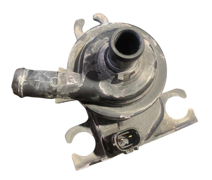
water was still, confirming the pump had failed.
Had to remove the front bumper and passenger-side headlight to get to the inverter pump.
A scan of the vehicle revealed the fault code, P0A93 – Inverter cooling system performance. The first step was to check the inverter cooling circuit for leaks or abnormalities.
No issues were found, so tested the inverter pump for power supply and it had power. Next, removed the cooling cap from the inverter fill bottle to check coolant flow. If the pump was working, there should have been a steady
Following installation of the new pump, I vacuum-filled the cooling system because the heatsink for this drivetrain’s motor/generator 2 (MG2) is well known for trapping air locks.
Bench-testing the old pump confirmed it was seized.
Diagnostic time for this job was one hour and repair time two hours.
Daniel Lambert
Optimus Automotive CARDIFF, NSW

Modern workshops are under constant pressure to complete repairs faster without compromising quality. Choosing the right sealing solution can be just as important as the repair itself and help reduce downtime and keep vehicles moving.
Building on its trusted range of traditional gaskets and sealing products, Permaseal has introduced a new range of RTV Silicone Sealants engineered for today’s workshops and serious DIY enthusiasts.
With application coverage for more than 12 million vehicles on the road, the range complements Permaseal’s existing gasket offerings, helping reduce time spent sourcing parts and improving turnaround times.
The new RTV Silicone Sealants range features three application-specific products: Sump, Housing and Manifold & Exhaust. Rather than relying on the complicated colour-coded labels common throughout the market, each product is clearly named after its primary application, making selection intuitive for experienced technicians and DIY users.
The bold, workshop-ready packaging reflects the high-performance formulation
inside and helps users quickly identify the correct product with confidence.

withstand operating temperatures up to 260°C, with intermittent spikes to 371°C.
A neutral-cure, high-performance, flexible RTV sealant suitable for engine and driveline applications involving permanent oil contact or oil wash, including sumps and timing covers.
Its flexibility makes it suitable for sealing different materials such as pressed-metal components against solid blocks. The oxime-cure, sensor-safe silicone can withstand operating temperatures up to 260ºC, with intermittent spikes to 371ºC.
A neutral-cure, high-performance RTV sealant suitable for engine applications exposed to high vibration or high torque loads due to close bolt spacing on cast housings, where less flexibility is required. The oxime-cure, sensor-safe silicone can
A neutral-cure, high-temperature RTV sealant suitable for engine applications exposed to higher temperatures and wider sealing surfaces.
The oxime-cure, sensor-safe silicone can withstand operating temperatures up to 399°C.
The Permaseal RTV Silicone Sealants range has been designed for professional workshops and DIY enthusiasts, offering application-specific solutions to simplify product selection and inspire confidence with every repair.
• Find out more, including technical specifications, application information and safety data, at permaseal.co or permaseal.co.nz

The Australian Automotive Aftermarket Association (AAAA) has welcomed the Australian Competition and Consumer Commission’s (ACCC) announcement that major online marketplaces have strengthened their commitment to protecting Australian consumers from unsafe products sold online.
The Australian Product Safety Pledge now includes Temu and Gumtree alongside Amazon Australia, eBay Australia and AliExpress. Participating marketplaces have committed to product safety measures that go beyond current legal requirements, including annual reporting on their progress.
AAAA Chief Executive Officer Stuart Charity said the strengthened pledge was a positive step for consumers and an important reminder that product safety extended well beyond general retail goods.
‘Online marketplaces are now a normal part of how Australians shop and consumers are entitled to expect that products sold through these platforms are safe, traceable and fit for purpose,’ said Charity.
Charity said that expectation was particularly important when motorists were purchasing vehicle parts online as a component that appeared suitable from an online listing
may not be the right part for that vehicle, repair or the safety systems that relied on it performing exactly as intended.
He said the AAAA was encouraging motorists to discuss replacement parts with their qualified technician before purchasing.
‘There are often a range of legitimate parts options available for a repair, including high-quality aftermarket parts, vehicle manufacturer-branded parts, recycled parts, refurbished parts and remanufactured parts,’ said Charity. ‘Choice is important but safe choice requires good advice.
‘The right choice depends on the vehicle, the repair, the quality and condition of the part, its provenance, whether it is fit for purpose and whether the workshop can stand behind both the part and the labour.’
Charity said consumers also needed to understand why many professional workshops were reluctant to fit customersupplied parts as independent repairers were
The Perth Automotive Training Event (PATE) returns on September 11 and 12 with a program designed around the needs of technicians, apprentices, workshop owners and managers.
Presented by the Automotive Service Dealers Network (AASDN) West, PATE brings together trainers from across Australia who combine technical knowledge with genuine industry experience. The focus is on information that can be understood, discussed and applied in the workshop rather than theory that is difficult to translate into day-to-day work.
The 2026 program covers diagnostics, diesel systems, electric-vehicle (EV) safety, customer service, leadership and business performance. In-depth masterclasses sit alongside targeted workshops, allowing attendees to choose sessions that suit their role, experience and business priorities. Businesses also have greater flexibility in how they attend. One-day and two-day passes are available, with discounted pricing
for AASDN West members. This is to make it easier for workshops to send the right people to the most relevant sessions while managing time away from the business.
Training will be delivered through a mix of interactive classroom sessions and practical workshop-based learning. Attendees can work through concepts with trainers, ask questions about real situations and see how the methods apply beyond the training room. PATE also provides something that can be difficult to create inside a busy workshop –time to compare ideas with other technicians, owners, trainers and suppliers. These conversations allow participants to test their own approach, find new solutions and return to work with a clearer plan.
AASDN West will again deliver PATE
responsible for the quality and safety of the work they performed while also managing warranty obligations on both parts and labour.
He said when a customer supplied a part purchased online, the workshop may not be able to verify where it came from, whether it had been correctly described, whether it was subject to a recall, whether it had been damaged, whether it met Australian requirements or whether it was appropriate for that particular repair.
‘In many cases, the safest and most responsible approach is not to fit parts where quality, compatibility, provenance and fitness for purpose cannot be verified,’ said Charity. ‘The ACCC’s announcement is a welcome reminder that online product safety is not just a retail issue.
‘In the automotive sector, the safest choice is to let your trusted repairer source the right part for your vehicle.’
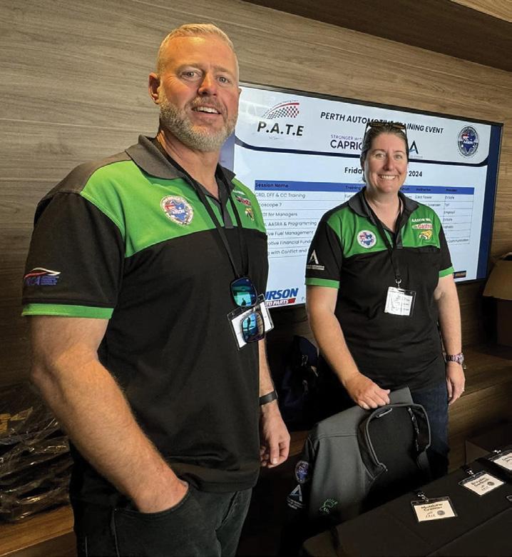
with the support of Capricorn as event partner, a partnership that reflects a shared commitment to practical training and stronger capability across the automotive industry.
For workshops looking to develop their people and respond to new technical and business demands, PATE 2026 offers focused training, useful industry connections and ideas that can be put to work straight away.
• Find out more at aasdnwa.com.au