World: 14-14 Max Bowyer, 996270
Foundations of Design : REPRESENTATION, SEM1, 2017 M2 JOURNAL - FLATNESS vs PROJECTION Max Bowyer
996270 Colby Vexler + Studio 14
1
WEEK 3 READING: TITLE OF READING
Question 1: What is Pictorial Space according to Le Corbusier? (Maximum 100 words) Pictorial space is described by Le Corbusier to be a “space that cannot be entered or circulated through... viewed from a distance, and is therefore eternally resigned to frontality.” He identifies the prior use of black and dark tones in creating shadow, therefore projecting an image or landscape forward while giving the impression of space that doesn’t exist. Instead, Le Corbusier utilizes texture and colour to contrast and project distant space. By refraining from using blacks, Le Corbusier maintains his view that it remains a frontal image.
Question 2: The Flatness of Le Corbusier’s painting’s are attributable to two properties. What are they? And what are these pitted against?(Maximum 100 words) Le Corbusier utilizes the object along with the “constellation of objects” that when combined create a sense that they sit along one plane, ensuring it remains parallel to the viewing plane. He used this system to give the viewer the frontal perspective of the object, then by applying colour and texture, he is able to contrast the receding imagery against the ground and surrounding area, therefore creating depth without the use of blacks all the while effectively retaining a flat frontal viewing plane.
2
MARIO’S WORLD
1-3_14
1-3_5
3
1ST MARIO’S WORLD
A combination of preparation for the next step and angular restrictions left this projection a more simple that anticipated. I prepared what would be the start of a lava pit hidden in the dividing wall between the two levels while projecting the holes in that same wall. This combined with the extended roof which i used to provide another lighting source and walkway in the form of a lava pool.
4
COMBINED MARIO’S WORLD
The final outline for the mario world. Combining world 1-3.5 with 1-3.14. The use of a lava lake on the furthest section justifies the light source coming from that hidden area. Similarily. the formation of the dividing wall means that the previous far end of the first projection can no longer be viewed.
5
WEEK 4 READING: TITLE OF READING Complete your reading before attempting these questions:
Question 1: Explain the difference between Pictoral (in this case perspectival) space and Projection? (Maximum 100 words) Pictorial space is a representation of what exists due to the parallel nature of the frontal view, meanwhile projection, including axonometric projection, with its lack of frontal parallel view can enable us to see what could not previously be viewed, meaning that where there is a vanishing point in pictorial space, there is none in axonometric projection. It therefore creates that which did not previously exist, opening a much larger window for creative license. However, because of this, the accuracy of the object can be lost as new information is created.
Question 2: Where did Axonometric projection first arise, and why? (Maximum 100 words) Axonometric systems of projection can date back ancient periods with the earliest being represented in a military context. Specifically, it was utilized to identify the expected path of projectiles, retaining its accuracy while enabling to plan what is not yet there. Progressing into the eighteenth and nineteenth centuries however, Axonometric projection had begun to be utilized by engineers and as it was able to simultaneously provide accuracy of the object while enabling a large sense of creative license. Meanwhile, it also developed the use of geometry in creating object for scientific and mathematical reasons.
6
ILLUSTRATED MARIO’S NEW WORLD World: 14-14 Max Bowyer, 996270
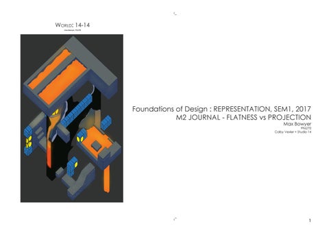
The final projection of Mario world 14-14 focused on several things. Achieving a sense of realism in the lighting levels was a key factor. To do this, the use of a gaugasian blur set at a low opacity with a wide radius gave a glowing effect that relfected that of the light found in the original images where the light sources were hidden. The shape of the dividing wall also required the most amount of work, this was due to having to include both backgrounds while maintaining accuracy. I was able to identify the clashes and work each into eachother until they became flowing. As a result however, a lot of the first walkway was cut off in order to maintain accuracy.
Insert your annotation
7
8
APPENDIX
Lightly sketched grid, this provided the parameters and height restriction that i would need to keep to throughout the drawing process.
Drawing up the original grids to project the dividving walls gaps
Begining the initial prjection process. Projected backwards to relfect its position in the final axo
9