ETS3 Masterclass in Structural Behaviour, 2019-20
Group 2
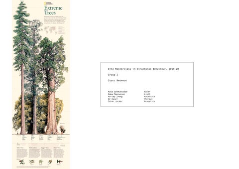
Coast Redwood
Nata Dzhmukhadze Water Emma Magnusson Light Hailey Zhang Materials Oz Caspi Thermal César Jucker Acoustics
Structural Glossary 3 Introduction 4 Art Gallery Beam Design
5
University
University Structural Scheme Design
8
University Stability Scheme Design 18 University Construction Process
23
University Foundation Process
28
Bridge Design
34
Arboretum Design 37 Tree Analysis 38 Site Analysis 40
Arboretum Design Concept for Planning
42
Structure Design Structural strategy and load path
47
Structural elements
48
49
Stability system and horizontal load path
Foundations
50
Thermal and Ventilation Design
51
Water and Drainage Design
53
Acoustic Design
55
Lighting Design
57
Materials and Insulation
59
Cost and Construction Programme
61
Sustainability
63
Construction Process
65
Alternative Design and Analysis
67
Structures Summary
68
rt
upport
compression
tension
Cantilever Beam
Simply Supported Beam
STRUCTURAL GLOSSARY
tension compression
1. Compression Force (Axial) A force directed verticaly along an axis.
10. Cantiliver Beam
compression
tension
Support 2.Roller Bending Moment
18. Horizontal Loads Lateral loads, mainly coming from soil in our case.
load
load
Cantilever Beam
11. Fixed Beam Simply Supported Beam
19. Foundations The connection to the ground of a structure, transferring the loads.
Fixed Support
3. Bending Stress The combination of the trilogy of primary stresses and leads to rotational distortion.
Bending Moment
12. Stress The force/unit area applied to a material.
20. Formwork tension Process of making a mould in order to cast concrete.
compression
load
load
Simple Support 4.Pinned SectionSupport Modulus A geometric characteristics of a specific cross-section.
13. Strain The measure of extent of deformation.
Roller Support
Simply Supported Beam
compression
Fixed Support 5. Roller Support A support that is able to rotate freely.
14. Deflection
Roller Support
load
Bending Moment
compression
compression
Pinned Support Roller Support 7. Fixed Support Roller Support
Fixed Support Pinned Support 9. Simply Supported Beam. A beam that attains a pinned support and a roller support.
Simple Support
Pinned Support
Fixed Support 15. Truss Simple A truss is an Support assembly of beams or other load elements that creates tension a rigid structure.
tension
tension compression load
Cantilever Beam 23. A vault An arched structure, usually of masonry or concrete, serving to cover a space.
Cantilever Beam compression
16.Building Loads weight Beam loads wich act on a structure. Cantilever Beam SimplySeflt Supported Simple Support
17.Shear Walls A vertical structural wall that can take lateral forces. Made usually out of concrete.
load
24. Rain water harvesting Bending Moment The process of harvesting rain water from glasses or slopes.
25. Carbon filter Carbon filtering is a method of filtering that uses a bed of activated carbon to remove Bending Moment impurities from a fluid using adsorption. 3
Simple Support Pinned Support
Simply Supported Beam
Simply Supported Beam Fixed Support
22. Retaining Wall compression A structure designed to restrain soil.
tension tension
load
6.Pinned Support
compression
21. Convection Ventilation The process of cooling or heating a space tension via a natural air movement due to speciCantilever Beam fic architecture decisions. High windows, load Skylight
tension
INTRODUCTION
For the first term of Environmental Technical Studies, we got assigned a brief to impose a Hooke Park in Bedford Square. We worked in groups of five and got given a tree species to work with. We needed to put the programs of Hooke Park in the square: a lecture hall, a large workshop, offices, bathrooms and general facilities. We were assigned the Redwood Tree – meaning we needed to create an environment friendly to that particular tree. Researching the ideal environmental condition of our tree, and developing a strategy for how we can make the tree survive in Bedford Square. The course is a full design brief – and other than creating a working environment for our specific species we also needed to research everything related to producing a building – the structural design, the lighting design, the thermal aspects ie insulation and materials, sustainability and cost, water, as well as acoustics (our design needed to include a very noisy environment next to a very quiet one). 4
ART GALLERY BEAM DESIGN
5
ART GALLERY BEAM DESIGN
6
UNIVERSITY
UNIVERSITY STRUCTURAL SCHEME DESIGN Nata Dzhmukhadze
Morwell Street
Bedford Square
GROUND FLOOR
SECOND FLOOR
ROOF PLAN
6
8
BASEMENT
Primary Masonry Masonry column beam
Timber column
FIRST FLOOR
THIRD FLOOR
Secondary Timber beam
8
UNIVERSITY STRUCTURAL SCHEME DESIGN Nata Dzhmukhadze
ROOF
14.00 m
03
11.00 m
02
8.00 m
01
5.00 m
GND
1.00 m
B01
-2.00m bgl
ELEVATION
A. Structural Grid: Try 6m x 8m B. Floor elements Masonry Primary beam Grid 6 by 8m Typical L/d 4-12 so Grid Pass Span/Depth=10/16 Depth=Span/10 to span/16 6000/10 to 6000/16 600mm to 375mm Use 400mm as it is quite thick the ceiling height would be 2600mm which is ok, but on the lower side Timber Secondary Beam Grid 6 by 8m Typical span L/d 5-12 pass so Grid Pass Span/Depth=14 to 18 Depth=Span/14 to Span/18 8000/14 to 8000/18 571mm to 444mm Use 444mm
SECTION
SECTION
D. Retaining walls Reinforced Masonry Retaining Wall Typical Height 1-6 Here 2m so Pass H/D=10 to 15 Depth=Height/10 to Height/15 2000m/10 to 2000m/15 200mm to 133mm Use 200mm
C. Vertical Support Elements Masonry column Typical 1-4m - 3m - Pass Height/Depth 15 to 20 Height/15 to Height/20=Depth 3/15 3/20 0.266 to 0.2 Use Depth=D=0.244 Use 244mm thick column Masonry column Typical 1-4m - 4m - Pass Height/Depth 15 to 20 Height/15 to Height/20=Depth 4/15 4/20 0.2 to 0.15 Use Depth=D=0.17 Use 170mm thick column
Timber
Masonry
Axo View
Timber Column Typical 2-4m - 3m pass Height/Depth=15 to 30m Height/15 to Height/30=Depth 3/15 to 3/30 0.2 to 0.1 Use Depth=D=0.152 thick
Warm Axo View
9
UNIVERSITY STRUCTURAL SCHEME DESIGN Emma Magnusson
10
UNIVERSITY STRUCTURAL SCHEME DESIGN Emma Magnusson
11
UNIVERSITY STRUCTURAL SCHEME DESIGN Hailey Zhang
12
UNIVERSITY STRUCTURAL SCHEME DESIGN Hailey Zhang
13
UNIVERSITY STRUCTURAL SCHEME DESIGN Oz Caspi
14
UNIVERSITY STRUCTURAL SCHEME DESIGN Oz Caspi
15
UNIVERSITY STRUCTURAL SCHEME DESIGN César Jucker
The brief asked us to understand and develop a structural grid with fixed span and placement of columns for a specific university located in Bedford square. The ceiling heights were predetermined, in order to for us to determine the depth ratio of floor height depending on the span that had to be bridged between the columns.
16
UNIVERSITY STRUCTURAL SCHEME DESIGN César Jucker
Basement
First floor
Ground floor
Second floor Grid: 6m x 8m
Columns
RC two way Typical span: 6m to 12m
Typical height for multistorey 2-4m ___ works for 3 to 4m
Typical L/d = 25 to 30 h/d = 6-15m = 6000/25 to 6000/30 Max = 4000/6 to 4000/15 = 240mm to 200 = 666mm to 266mm Use 220mm Use 300mm
Third floor
17
UNIVERSITY STABILITY SCHEME DESIGN Nata Dzhmukhadze
A. Shear wall for masonry Masonry Wall Height=3m Typical 1-5m Height/Depth=18-22 Height/18 to Height/22=D 0.2 to 0.1 D=0.152 Use 152
Building is stabilised with Retaining masonry wall, shear masonry walls and timber bracing on all 4 sides.
B. Timber Bracing Timber Braced frame 2-4 storeys 3 storeys within limit so pass C. Glued laminated timber beam with roof deck Typical span 4-30 grid 6 by 8m so Pass Span/Depth=15 to 20 Depth=Span/15 to Span/20 8000/15 to 8000/20 533 to 400 Use 400mm
18
UNIVERSITY STABILITY SCHEME DESIGN Emma Magnusson
19
UNIVERSITY STABILITY SCHEME DESIGN Hailey Zhang
20
UNIVERSITY STABILITY SCHEME DESIGN Oz Caspi
21
UNIVERSITY STABILITY SCHEME DESIGN César Jucker
The shear wallls don’t extend all the way between the columns to allow more daylight to come in.
Shear/ retaining Walls The shear walls are placed all along the basement.. Retaining Wall Typical Height 2-3m Height 2.5m H/d 10-12 2.5/10 - 2.5/12 Thickness 0.25 m
22
UNIVERSITY CONSTRUCTION PROCESS Nata Dzhmukhadze
Masonry and Timber Construction 1. Excavation and Compacting the Ground Excavation of the ground for the construction of wall foundations. The bottom is compacted using hand compactors.
4.Construction Vertical primary and secondary beams, floor slabs are placed.
Compactor Tool zoom in
2. Foundations Before building the block wall, the foundation must be level, and clean so that mortar will properly adhere. Concrete foundation 3 times bigger the brickwall is excavated and then placed. Steel rods for brickwall are placed. 5.Construction Cement, Thick sand, Water are mixed for the mortar and the brick wall assemblage begins. 4.Placing the forms The forms are made from wood panels. Bracing of the panels is needed to assure stability of the form.
For finishing of wall and ceiling surface it is necessary the use of scaffolds.
Vertical structure out of steel for Masonry and Vertical Timber columns are placed.
23
UNIVERSITY CONSTRUCTION PROCESS Emma Magnusson
24
UNIVERSITY CONSTRUCTION PROCESS Hailey Zhang
25
UNIVERSITY CONSTRUCTION PROCESS Oz Caspi
26
UNIVERSITY CONSTRUCTION PROCESS César Jucker
Excavation
Columns are being cast
Propping and formwork
Ground slabs are cast
Unproping
27
UNIVERSITY FOUNDATION DESIGN Nata Dzhmukhadze
3600 kN/sq.m. Shallow foundation design Design foundation for the column Area supported by the column 6 by 8m 6mx8m=48sq.m. Masonry clad timber frame 10-15 kN/sq.m. Use 15 as the base is dominantly masonry Load on column =Area x Load x Number of floors 48sq.m. x 15kN/sq.m. x 5 =3600kN on the corner column Allowable bearing pressure 10 x N =150kN/sq.m. 3600/150=24sq.m. Foundation needs to be 4.8 by 4.8m so that it doesn’t sink into the ground
28
UNIVERSITY FOUNDATION DESIGN Emma Magnusson
29
UNIVERSITY FOUNDATION DESIGN Hailey Zhang
30
UNIVERSITY FOUNDATION DESIGN Oz Caspi
31
UNIVERSITY FOUNDATION DESIGN César Jucker
Are supported by column : 4m x 3m = 12m2 Precast Concrete Floor Slabs : 15-20 kN/m2 Concrete Structure : 20 kN/m2 Load od column : Load x Area x Amount of Floors : 20 kN x 12 x 5
= 1200 kN/m2
Bearing pressure : F/A Allowable bearing pressure : 10 x N = 200 kN/m2 Area of Foundation Block : 1200kN/200kN/m2 = 6m2 2,45m x 2,45m
2,45m
32
BRIDGE
28
BRIDGE DESIGN
Entrance from the front members room
36, Bedford Square
Entrance to new Hooke Park Bedford Square 34
BRIDGE DESIGN
35
ARBORETUM
ARBORETUM DESIGN
We have designed a building retaining two Redwood trees, parts of their trunks exposed within the interior. The building is placed underground, in order for the trees to have additional support and not to be too unstable as they grow incredibly high and have a quite shallow root system. We have restricted the growth of the tree to thirty metres rather than the possible 150, by creating an enclosure underneath the foundation of the building which retains the root system and hence stops the tree from growing upwards after a certain point. Using a brick vault allows for the topography to be continuous, and doesn’t disrupt the use of the square as a leisure space.
37
TREE ANALYSIS
- Common names include coast redwood, coastal redwood and California redwood. It is an evergreen, long-lived, monoecious tree living 1,200–1,800 years or more. - This species includes the tallest living trees on Earth, reaching up to 115.5 m in height (without the roots) and up to 8.9 m in diameter. - Coast redwoods occupy a narrow strip of land approximately 750 km in length and 8.0 km in width along the Pacific coast of North America. - This native area provides a unique environment with heavy seasonal rains up to 1,500 mm annually. Cool coastal air and fog drip keep this forest consistently damp year round.
38
TREE ANALYSIS
- According to the National Park Service, temperatures in the redwood forest range from -5 °C to 25 °C all year. Winters are occasionally frosty and snow is not uncommon. - When young, redwoods need partial shade to protect them from sunburn. A well-drained spot with a neighboring tree for shade is a smart place for them, but as they grow they should shoot above neighboring trees to receive the benefits of full sun exposure. - Redwood like a pH that is on the acid end from 4.5 to 6.5. - The root system is composed of shallow, wide-spreading lateral roots.
39
SITE ANALYSIS
- Total surface ± 6’500 sqm - London, arrogates on average 894 mm of rainfall per year. - London clay soils provid an ideal acidic base for the redwood. - Bedford square is today composed of seventeen plane trees. - It provides a natural canopy vital for the development of a young redwood.
40
SITE ANALYSIS
Sunrise - June 21st
Sunrise - March 21st
Sunset - June 21st
- Redwood have been grown in the UK since the early Victorian period. Sunrise - December 21st
- Today redwood population in the UK is estimated up to 1’000 specimens with 484 specimens census in Essex.
Sunset - March 21st Sunset - December 21st
41
ARBORETUM DESIGN CONCEPT FOR PLANNING Nata Dzhmukhadze
Rain water is collected off the roof surfaces and pours inside the structure
Workshop
Filtration unit
Drainage pipes are connected to the existing AA drainage system to get rid of the used water
Filtered water is spread into the workshop
Infiltration tank for the excess water is used to recharge ground soil Re-use tank for rainwater harvesting
42
ARBORETUM DESIGN CONCEPT FOR PLANNING Emma Magnusson
43
ARBORETUM DESIGN CONCEPT FOR PLANNING Hailey Zhang
44
ARBORETUM DESIGN CONCEPT FOR PLANNING Oz Caspi
45
ARBORETUM DESIGN CONCEPT FOR PLANNING César Jucker
46
STRUCTURAL STRATEGY AND LOAD PATH
47
STRUCTURAL ELEMENTS
Retaining wall
48
STABILITY SYSTEM AND HORIZONTAL LOAD PATH
49
FOUNDATIONS
insulation membrane waterproof membrane
vertical steel reinforcement
prefabricated concrete foundation wall
horizontal steel reinforcement
interior wall
waterproof insulation
SOIL
concrete floor slab
concrete raft foundation
SOIL
Fig. detail section showing foundation
50
THERMAL AND VENTILATION DESIGN Oz Caspi
51
THERMAL AND VENTILATION DESIGN
PRODUCED BY AN AUTODESK STUDENT VERSION
Oz Caspi
52
WATER AND DRAINAGE DESIGN Nata Dzhmukhadze
1.Rain water is collected off the glass roof and pours inside the foundation water filtration tank.
1. Rain water is collected off the glass roof and pours inside the foundation water filtration tank.
2. 1st filtration compartment unit.
3. 2nd filtration compartement unit.
2. 1st Filtration compartement unit.
2. 2nd Filtration compartement unit.
2. Filtrated water is spread into the workshop and bathrooms.
4. Filtrated water is spread into the workshop and bathrooms.
2. Drainage pipes are connected to the existing to Bedfor Square drainage system to get rid of the water.
5. Drainage pipes are connected to the existing Bedford Square drainage system to get rid of the water.
53
WATER AND DRAINAGE DESIGN Nata Dzhmukhadze
Rain-harvesting Collection Water Tank is stored underground. Water is spread mainly through the central part of the building to the bathroom, workshop and kitchen.
Area of the glass roof: 218 sq.m. Annual Precipitation litres: 594l Total amount of water stored: 129,494 gallons.
54
ACOUSTIC DESIGN César Jucker
Clay brick 90 x 90 x 120 mm
Acoustic brick 180 x 160 x 300 mm
Average [dB] Outside - Quiet garden: 30
Vented airspace 30 mm
- Street with traffic: 60 Inside - Conversation, 1m: 70 - Lound music on radio: 80 - Hammer: 120
55
ACOUSTIC DESIGN César Jucker
Acoustic film
Outside
Inside
Noise
Acoustic laminated glass
56
Su
nr
LIGHTING DESIGN Emma Magnusson
Sunset - June 21st
Sunset - March 21st Su
ns
et
-M
arc
h2
ise
-J
un
e2
1s
t
Sunrise - June 21st
Sunrise - March 21st
1s
t
Sunset - December 21st
Su
ns
et
-D
ec
em
Sunrise - December 21st
57
be
r2
1s
t
LIGHTING DESIGN Emma Magnusson
In designing the lighting of the building, we had to take into consideration the issue of having the building underground making it ultimately quite dark. The light in London is sufficient for the redwood tree to grow healthily, hence there was no need to spend time designing a solution for the design of the light for the tree. The tree normally grows in forests – and so our choice to keep only two trees free standing means plenty of light reaches them. For the building we use the entire length of the long side creating a sky–light of 50m x 2m, allowing for plenty of light to reach large parts of the interior. We have divided the space so that no walls are covering the light coming in. We have placed the building in a direction referring to sunpath diagrams as well as looking at how the existing trees are placed across the square, optimising the amount of sun reaching through this sky-light. Two additional openings in the ceiling are placed around the trees, allowing for more light to enter through to the back of the building. We have chosen to plant the trees at a stage in their life so that they are tall enough for the crown never to cover these openings.
58
MATERIALS AND INSULATION Hailey Zhang
The school would be conctructed in 2 major materials: brick masonry and concrete. As the school is underground level with no more than 3 stories and need to deal with the strong root system of the redwood, a concrete raft foundation is suitable considering the strength and cost. A 300mm concrete raft foundation with steel grid reinforcement would go through the whole footprint of the building; above it, a layer of 30mm waterproof membrane would be the main insulation between the foundation and the actual interior floor plate. The steel reinforcement is designed to prevent cracking and it needs to be increased in density when it goes to the «pot» of the redwood tree, where the pressure from the root system would increase. Pre-fabricated concrete retaining walls with both vertical and horizontal steel reinforcement would be assembled on-site with the raft foundation, with insulation membrane and waterproof membrane to resist the moisture from the loamy soil on site which leads to the crack of the wall.
material decision - underground architecture As a general rule, the thermal conductivity of soil increases with increasing moisture content. When dealing with sunken interior and buried hot-water pipes, a surrounding soil of low thermal conductivity is required, to minimize heat loss from the space and pipes to the ground. Thermal conductivity measures the ease with which heat can travel through a material. Above are the comparison of the effectiveness of several materials that were taken into consideration, considering thermal conductivity and specific heat capacity. Other factors taken into consideration include sustainable, strength for long-span structure, construction convenience (transporting material and on-site construction). The conclusion as a group leads to the decision of using prefabricated concrete as the base and walls and brick masonry as the roof.
59
MATERIALS AND INSULATION Hailey Zhang insulation membrane waterproof membrane
vertical steel reinforcement
prefabricated concrete foundation wall
horizontal steel reinforcement
interior wall
waterproof insulation
SOIL
concrete floor slab
concrete raft foundation
SOIL
Fig. detail section showing foundation
material
specific heat capacity
thermal conductivity
effectiveness
density
advantages
disadvantages
stone
1000
1.8
high
2300
durable, weather resistant, long lasting
transport to central london
concrete
1000
1.13
high
2000
mouldable, can be strengthen, low cost
crack due to moisture expansion
brick
800
0.73
high
1700
sustainable, low maintenance
absorbs water
unfired clay brick
1000
0.21
high
700
fire-resistant, good thermal mass
poor sound insulation, non-water resistant
timber
1200
0.14
low
480
non-toxic
biotic factor
steel
480
45
low
1200
low self weight, light structure
poor thermal mass
60
SUSTAINABILITY
Sustainability B. Water Drainage
1. Rain water is collected off the glass roof
2. The water slides down the glass roof, to the 1st installed pre-tank filtration unit which uses activated carbon to clean the water.
3. 2nd Filtration compartement unit.
4. After the water is moved to the third settlement if in any case there is an excess water then the water can be left outside.
Rain-harvesting Collection Water Tank is stored underground. Water is spread mainly through the central part of the building to the bathroom, workshop and kitchen.
Area of the glass roof: 218 sq.m.
5. Filtrated water is spread into the workshop and bathrooms.
6. Drainage pipes are connected to the existing Bedford Square pipes where the used water is directed to.
Annual Precipitation litres: 594l Total amount of water stored: 129,494 gallons. 63
SUSTAINABILITY
Sustainability A. Ventilation Ventilation is made out of concrete tubes that are situated underground. Tubes are placed very low so the hot airs rises up due to the law of Convection Currents. In summer the underground soil is cooler than the outside temperature so when the air passes through the tubes it coolls down naturally. In winter the warmer air gets underground as the temperature underneath is warmer than the temperatur outside.
64
CONSTRUCTION PROCESS
1. excavation
3. foundation is cast, pipes inserted
2. excavation temporary support
4. tree is planted
65
CONSTRUCTION PROCESS
5. building of walls, temporary
6. inserting windows, doors etc.
66
ALTERNATIVE DESIGNS
Group 16 Comments
Group 9 Comments
* Point out more clearly on plan where redwood trees are Their diameter is very small? Young tree?
* Very nice deisgn, seemingly materials efficeint for quite large structure
* Enclosing them? How big the tree can grow ?
* Nice manipulation of insertion in foundation in order to support angled timber frame
* Why does the plan have so many corridors spaces ? Whole space seems a bit wasteful Canopy meeting the ground makes a lot of the space useless
* Beautiful detail drawing
* Unclear how foundation works together with roots system
* Will the reflective paneling bother the other side of the building ? Be good to see a diagram of the light reflection...
* What about cost, glass lokks quite costly...?
* What about the support of the trees - the very shallow roots make it unstable when on it’s own, exposed to strong winds * How do you make sure it doesn’t fall into British Museum
67
STRUCTURES SUMMARY
STRUCTURES SUMMARY
Nata Dzhmukhadze
Nata Dzhmukhadze
In conclusion, the Bedford square Brief and all the additional exercises have helped me to identify the fundamental facts about the stages of the structural construction of a building and the plot’s surroundings: structure, environment, foundations, historical maps, materials, construction sequence and sustainability as well as the methods of structural calculations. Bedford Square : The first idea that came to mind was to use the trunk of the tree as a structure and hollow out on the inside with the workshop situated underground. However, it would mean that we would have to transport the already grown more than 20m tree which would be very expensive. Another concept was to develop further the idea of digging underground and allowing the tree to grow with time. Underground vaulted space was the concept that was taken further to develop which helped us to decide on which structural and sustainable elements could be integrated in the final design. We have found that the chosen Redwood tree had properties suitable for the UK weather as it also grows in the UK area as Essex that has similar climate. As a result, the tree didn’t actually dictate the design and we had freedom in choosing and creating the workshop space as sustainable as possible. When finalised the concept, materials were chosen. Since the whole building had to be situated underground, be sustainable, have cheap costs and have vaulted spaces we have chosen masonry as the primary material. It is more sustainable than the initial material chosen - concrete and it is easier and cheaper to be built on site, especially the vaults. The wooden or cardboard frame work would be used to create the vaults. We have created 2 vaults with one of them having perfect acoustic system for the lecture hall. Another good sustainable strategy that is used in the design because of it’s underground situation is the ventilation. Concrete tubes ventilation creates warm and cooling air naturally due to the law of conviction currents. Water drainage is sustainable as well as ventilation as we use rain harvesting. Furthermore, the challenging process we encountered was allowing more light into the space itself, when the model was finally tested, the space inside wasn’t entirely dark but I think there could have been more ways of allowing more light into the structure by creating more vaults and skylights. However that would mean a more intricate woodwork for the roof construction. Overall, maybe it is not the most structurally interesting construction but I think it has met all the sustainability and lower costs. Additional Exercises: Masonry and timber I’ve found these exercises very interesting as they are very important bases for a construction of any building and influence the design as well. As well as learning more about the different masonry and timber elements, foundation and construction process I have also broaden my knowledge of other materials in comparison such as steel and concrete when comparing their structural properties and different elements of a building to the masonry and timber. Also, I’ve understood more the importance of the relationship of the site to the building, in particular the soil and foundations and the forces that are created with the structural elements. 69
STRUCTURES SUMMARY Emma Magnusson
I have further understood the technical complexities surrounding the construction of a large structure, and the many aspects of the planning and design around it. Specifically how placing a structure underground might in some aspects be helpful / energy saving, in other aspects (e.g. lighting) can create problems. We worked together as a group of five people, creating a full design scheme for a building on Bedford Square, with programs including a lecture hall and a wood/metal workshop. It is the first time since starting architecture training to attempt designing every aspect of a building. Additional to ‘just’ designing a functional building, we also added the restrictions related to making the largest tree in the world grow inside of it, in a safe manner. Another challenge was working together as a larger group – through which I suppose I learned some kind of project management.
70
STRUCTURES SUMMARY Hailey Zhang
In this year’s ETS: Master Class of structural behaviour, there are several subjects that we gained a further understanding on and I personally believe it would benefit the way how I consider architecture design with structure restriction or attraction involving. The subjects include long span structure design, construction and thermal and foundation design.
The most important subject that affects the later design, to me personally would be the long span design, where the depth of the span would affect the interiority significantly. The floor plate and the roof, in reality, could not be simply considered as a sheet of material - even if they are a thinshell structure like a vault, there are still limitations. The depth of the span associated with a lot of issues that have the potential to change the spatial quality and function, for example, skylight and occupiable space for different programmes.
Going further to our design to cooperate with the redwood, which is the most giant tree on the planet, we applied the knowledge of long-span structure on our new Hooke Park in Bedford Square. To prevent the depth of the span would take away space and natural lighting, we designed a masonry vault. The knowledge in the foundation lecture section helps us to find a possible way to cooperate with the redwood’s wide-spreading roots and make sure the building is stable. Apart from the vault and retaining walls, which are 2 fundamental elements of the design, we also introduced light wells, curved separation wall and concrete earth tube to achieve specific light, thermal and acoustic quality.
What I found peculiar about the course is that the way the glossary is taught and how they could be related to design. Instead of throwing out new terms and symbol that many people may have never known with and asking them to be inserted into formula, a more detail, clear lesson of these basic physics concepts could potentially be more useful.
71
STRUCTURES SUMMARY Oz Caspi
In this technical studies course I have learnt about adapting to a new and foreign environment. We were given the Redwood tree, in which does naturally grow in the United Kingdom. In order to conduct our brief we have made a deep research about the conditions, technical system it requires as well as different methods to construct structures a long side such a tree. I was given the task of ventilating our structure, which is underground. In order to solve this technical issues I did a research in which I have learnt a lot about passive and sustainable ways of ventilating an underground building. My materials were timber and steel both very versatile and very commonly used in architecture yet, I did not had such a great understanding of the way the function and support one each other through complex systems. More than that, I learnt a lot about the relation between structures and their support, by practicing different calculations in order to stabilise and support the structure.
72
STRUCTURES SUMMARY César Jucker
The structural principles covered in this course started with beams and columns in the art gallery exercice. In order to diversify our structure knowledge, we were then asked to developed a structural scheme design for a university based in Bedford Square. For this exercice, I’ve been using concrete as requested by my tutor Ciaran. This specific material, allowed me to learn different structure type such as, retaining wall, self supported slabs and shear walls. The next step of the university exercice, allowed me to have a deeper look into the foundation of a building of a multistory building. The arboretum exercice, due to our underground design, brought a better and deeper understanding of retaining walls, how to bring light in undergroud spaces (skylight) and, in my case, to learn about the notion of acoustic. Finally, the vault introduced in our design allowed to understand how the load are transfered on a specif structureand how to deal with the intersection of different structure type (vault/retaining wall).
73
74
75