
Statistics


ISSN No. 1948-3031
PUBLISHER: Wayne Nielsen
MANAGING EDITOR: Kevin G. Summers
CONTRIBUTING WRITERS: Stewart Ash, James Barton, Bertrand Clesca, Dr Herve Fevrier, Stephen Jarvis, Brian Lavallée, Pete LeHardy, Vinay Rathore, Dr. Joerg Schwartz
Submarine Telecoms Forum magazine is published bimonthly by Submarine Telecoms Forum, Inc., and is an independent commercial publication, serving as a freely accessible forum for professionals in industries connected with submarine optical fiber technologies and techniques. Submarine Telecoms Forum may not be reproduced or transmitted in any form, in whole or in part, without the permission of the publishers.
Liability: while every care is taken in preparation of this publication, the publishers cannot be held responsible for the accuracy of the information herein, or any errors which may occur in advertising or editorial content, or any consequence arising from any errors or omissions, and the editor reserves the right to edit any advertising or editorial material submitted for publication.
Contributions are welcomed. Please forward to the Managing Editor at editor@subtelforum.com.
Submarine Telecoms Forum, Inc. 21495 Ridgetop Circle, Suite 201 Sterling, Virginia 20166, USA subtelforum.com
Copyright © 2012 Submarine Telecoms Forum, Inc.
November in America is the month we celebrate Thanksgiving. It is also the month SubTel Forum celebrates our anniversary of existence, that now being 11 years going strong.
When Ted and I established our little magazine in 2001, our hope was to get enough interest to keep it going for a while. We had a list of contacts, an AOL email address and a song in our heart; the hardest part was fooling the email system to let us send out 250 or so at a time.
When we had our first “positive” response we celebrated; when we saw 1,000 people download an issue we were ecstatic. Little steps moving in a positive direction.
In 2012, our 10th year of operation, we saw some dramatic changes to the dynamics. With the addition of the Cable Almanac and Industry Report, we realized downloads in the thousands, well above those typically seen. In the Spring alone we watched as the Cable Almanac peaked above 125,000 downloads – Wow! As if the industry had embraced what we envisioned, and it was humbling as well as electric for all of us.
With 2013 beginning soon, our 12th year, we have a few enhancements to the SubTel
Forum brand which we will be rolling out during the course of the year, and which we believe will further enhance your utility and enjoyment. We’re going to kick it up a level or two, and think you will like the developments . And as always, it will be done at no cost to our readers.
We will do so with two key founding principles always in mind, which annually I reaffirm to you, our readers:
» That we will provide a wide range of ideas and issues;
» That we will seek to incite, entertain and provoke in a positive manner.
So here’s to you, our readers and supporters.
Happy Anniversary and in the spirit of Thanksgiving, thank you as always for honoring us with your interest.

In This Issue...

news now
Alcatel mulling sale of submarine, enterprise units-sources
American Samoa eyes second submarine fibre cable
APTelecom Appointed as SACS - South Atlantic Cable System (Angola - Brazil Cable) Pre-Sales Manager for International Network Development
Arctic Fibre Applies For Canadian Landing Licence
Conroy mulls Government-funded subsea fibre link
Cross River Fiber Partners With Telx For Network Access Services
Cross River Fiber Supports Dark Fiber Connectivity Within the Healthcare Vertical, Extending Its New Jersey Backbone Reach By 50+ Miles
Cyprus Telecommunications Authority Deploys Infinera DTN-X Platform for 100G Mediterranean Subsea Network
eFive Telecoms Signs Up Undersea Cable Supplier
Emerald Networks Announces a Strategic Investment By Storage Engine, Inc.
Firms go through hell and high water in GBI Connects The Red Sea To Milan With Advanced 100G Technology From Xtera
Globe lays submarine cable to Boracay
Groups urge government to revise submarine cable
Huawei, ZTE, and the Slippery Slope of Excusing Protectionism on National Security Grounds
HYLAS 2 Gateway at Cyta Kim Dotcom to reboot NZ submarine cable and offer free broadband
ICPC: Call For Papers
Lat Am submarine network upgrades to 40G
Mitsubishi Electric Upgrades IMEWE Submarine Cable System between India, Middle East and Western Europe in Record Time
MTN Announces Commercial LTE Plans
MTN to bring LTE to 3 SA cities
Namibia: Titanic Battle Looming in Telecom Sector
NBN to build undersea cable to US if prices don NTC plans new submarine cable
Prysmian SpA : Prysmian to develop first-ever high-voltage submarine power link in Turkey to connect Asia and Europe across the Dardanelles strait
Radius Oceanic Communications and Cyta announce Eastern Mediterranean cooperation through the POSEIDON System
Reliance Globalcom may acquire optical network gear from US company Ciena
Sea Fibre Networks Launch the Staffordshire Gateway
Seaborn Networks signs contract with Alcatel-Lucent to build US-Brazil submarine cable network
Shrinking Arctic ice and a golden fibre-optic opportunity
Silent Fibre-optic War Rages
Slattery SMD and BORD Sign Joint Venture
Submarine Cable Almanac - Issue 4
Submarine cable outage hits Kiwi internet
SubOptic 2013 Call for Papers: 164 Submissions Received!
SubOptic 2013 Early Bird Registration Now Available
T-Mobile: New CEO Legere Faces Promising Problems
Tata Communications appoints Rangu Salgame as Chief Executive Officer of Growth Ventures
Telefonica selects Infinera DTN-X platform for 100G SAm-1 submarine cable upgrade
The 2012 Presidential Election and Its Future Impact on Telecommunications and Media Policy
TRAI to specify charges for Cable Landing Stations
Undersea cable support
Vietnam telcos to join in Asian undersea Internet cable project
Vodafone Sees 500 Million Pounds in Costs From C&W Deal
WARCIP Updates on ACE Fibre Optic Project
Zanzibar Gets 100 MW Cable Link To Mainland


notes on The Upgrade Market

Stephen Jarvis
The ongoing march of technology has always been an important part of the submarine cable industry. When pertinent technology becomes available it redefines many different aspects of the industry. Possibly the most important of which has been the creation of optical cable which expectations of available capacity.
One of the most recent technologies that have changed not only the equipment used but the way business is done has been capacity upgrades. For the first time systems can be improved either to meet their full design capacity or, in the
case with newer optical systems, beyond capacity. This is opposed to completely laying new cable with better technology to replace the old model.
The use of upgrades to improve a system has become growingly popular. This has given rise to a number of companies that either can or even specialize in providing upgrades. One such company is AlcatelLucent.
“We’ve sold upgrades since the optical era,” said Norma Spruce, ASN Marcom Director. She explained that since optical

became available roughly 20 years ago, they had dealt in a few forms of upgrades.
It wasn’t until 2009, however, that the newest kind of upgrade became available, according to Olivier Courtois, AlcatelLucent system product line manager. This is thanks to developments in coherent detection, which has allowed possible upgrades to go up to or beyond 100 gigabits. It isn’t always easy though.
“You can squeeze more out of a system design,” said Spruce. “But only if you know what you’re doing.” The process
As observed by a number of publications and Press Releases, the number of cable systems that are being upgraded is clearly on the rise. One of the major factors contributing to the new popularity of upgrading an older system is the low price point. Rather than go through the ordeal of implementing a new system, owners are choosing to get a few more years of life out of their already existing systems with an upgrade.
of increasing capacity can change from system to system. The age, design, and a number of other factors dictate how much of an increase, how expensive it may be, or even if it can be done at all. Sometimes nothing can be done but increase to its ultimate capacity as dictated by the design.
The effect of upgrades on the market is an even more far reaching issue. In the lasting economic difficulty of the last five years, a more cost effective option that completely replacing the cable of a city to increase capacity opens more than a few doors. It allows for a new, specialized
market. It creates competition among system suppliers with this new market for the repeat business with owners. It even creates possibilities for owners to request designs that plan future upgrades into them.
The new options and facets provided by this new market have become increasingly important. The submarine cable industry, like so many others, is highly dependent on growth. System suppliers in particular are threatened when there aren’t new systems being regularly created. The movement in the industry created by upgrades allows

for money to be made that otherwise wouldn’t be.
New technology can always have surprising effects and always build on each other. 20 years ago, companies began laying optic cable, creating new possibilities for capacity and changing the market in doing so. Now, the growth of the relatively new upgrade market has changed the game again, giving cost effective alternatives for owners. It can only be wondered what next big shift will be thanks to this one.
As the popularity of upgrading systems jumps and the demand for capacity increases, naturally the market will respond with improved and cheaper technology. In 2009, the upgrades seen were majorly 10G upgrades, whereas now in 2012, you will find that 100G is the new norm. As the upgrade market heats up, competition will drive cheaper and faster upgrade technology.
Upgrades may utilize 10Gb/s, 40Gb/s or 100Gb/s transmission technology. 10Gb/s transponders may be used when low cost or rapid deployment is required; typically from 1 to 1 ½ times the original design capacity may be achieved; for example a system designed for 32 waves per fiber pair might be expanded to 40 or 48 waves. 40Gb/s upgrades have been offered for several years, but are rapidly being overtaken by 100Gb/s upgrades. 40Gb/s upgrades may deliver 2 to 2 ½ times the original design capacity; it is not usually possible to replace each 10Gb/s channel with a 40Gb/s channel, thus the improvement factor is less than 4. 100Gb/s upgrades have recently been announced, with the potential to achieve 4 times the original design capacity on some wet plant.
Owners may choose from these solutions to meet their specific needs: maximizing capacity, rapid deployment, lowest cost or some combination. The exact results depend on amplifier bandwidth, equalization, the chromatic dispersion map, and other factors. A typical upgrade will involve tests to characterize a fiber pair followed by trials of the equipment before a supplier commitment is made. Many upgrade designs now permit new channels to be added alongside existing channels, avoiding the need to remove existing terminal equipment from service.
(Excerpts from Submarine Cable Industry Report, Issue 1, July 2012)

Stephen Jarvis is a freelance writer in the Washington D.C. area. He has published articles and done editorial work with several publications including Submarine Telecoms Forum. Also, he has been a speaker for the Popular Culture Association / American Culture Association National Conference.

With new and better technology, competition will begin creeping in from unexpected places. Over the last few years, the upgrade market has almost wholly been dominated by Infinera and Xtera. Traditionally, this industry is dominated by installers, such as TE Subcom and Alcatel Lucent; however this new emerging market seems to be almost completely driven by faces relatively new to the submarine world.

All optical Submarine network Upgrades

Brian Lavallée
Although demand for intercontinental bandwidth continues to grow at a significant rate worldwide, intensified competition has resulted in significant price erosion. This means global network operators must find ways to cost-effectively upgrade their existing wet plants while cost-reducing them at the same time. Increasing channel rates from 10 Gb/s to 40 Gb/s and 100 Gb/s, using coherent-based transmission technology, is now the preferred method for increasing submarine network capacity. New submarine cables will still be deployed for other reasons though, such as increasing route diversity or providing ultra low latency connectivity. Upgrading existing submarine cables via channel upgrades eliminates or at least defers the substantial capital investment and associated risks related to time-consuming new cable builds. Although increasing channel rates does offer economies of scale to lower the cost per transported bit, there are other innovative options available to global network designers to lower network costs even further, such as ROADMs and “optical bypass” configurations.
Coherent-Based Transmission Technology
For decades, optical transmission technologies deployed over terrestrial networks were incapable of achieving distances associated with transoceanic networks. This meant submarine cable operators had little choice but to deploy costly submarine network-specific
transmission technologies over proprietary wet plants. The advent of coherent-based transmission technology, initially targeted for long distance terrestrial networks, has eliminated the need to deploy expensive submarine network-specific transponders. Each submarine cable system was custombuilt with design goals to maximize performance and reach. This led to each submarine cable system inheriting a unique optical performance “personality”, which greatly differed from terrestrial optical line systems.
The same coherent-based transmission technology can now be deployed overland and undersea, even over very long transoceanic routes. Although each submarine cable system has its own unique performance personality, coherent-based transmission technology can still be used, albeit to varying degrees, which is further testament to the flexibility and robustness of this revolutionary technology. The industry has adopted coherent-based transmission technology as the de facto
standard for upgrading submarine and terrestrial network capacities. A complimentary optical network technology initially developed for terrestrial networks can also be leveraged.
Reconfigurable Optical Add-Drop Multiplexer (ROADM)
The ROADM is another optical technology initially developed for terrestrial networks that has found its way into the Cable Landing Station (CLS). As wholesaling wavelengths increasingly becomes the industry practice for bandwidth purchases over global networks, keeping traffic within the optical domain from Point of Presence (PoP) to PoP, meaning no opticalelectrical-optical (OEO) conversion stages, enabled far more scalable, cost-effective, and simpler networks to own and operate making it a logical design choice for network planners, where possible. Wavelengths should never be converted back into the electrical domain unless subwavelength access is required, such as for

Figure 1: Traditional Cable Landing Station Network Design
grooming and/or switching purposes, or when limited by available link budgets.
Avoiding OEO stages minimizes latency, power/space requirements, network complexity, and most importantly, network costs. When wavelengths are the wholesale “currency” of the global network, they should only be converted back into the electrical domain at the very end points of the network link, which is typically the inland PoP, such as a data center. ROADMs allow wavelengths coming from the wet plant into the CLS to be switched while remaining in the optical domain to the inland PoP or forwarded to the next CLS as “express wavelengths”. Since the wavelengths remain in the optical domain for the duration of their travel, and utilize coherent-based optical transmission technology, they are inherently more secure, as they eliminate vulnerable OEO stages.
Transmission and Switching Technology Convergence
Over time, connecting standards-based terrestrial networks to proprietary submarine networks led to a distinct network demarcation point, as shown in Figure 1, which is typically located in the CLS. Although having served the telecom industry well for decades, this demarcation point can be significantly optimized by leveraging the latest in technology convergence, which until recently was simply not possible. SDH is the standard of choice in the world’s submarine

networks, as well as most of the world’s terrestrial networks, with the notable exception of the United States, which uses SONET. This means submarine networks that interconnect SONET-based networks to SDH-based networks require SDH/ SONET protocol conversion, meaning OEO stages are required. Optical Transport Network (OTN) is a global standard that can be used over submarine and terrestrial networks to replace SONET and SDH to help erase the need for the traditional submarine-terrestrial demarcation point, also referred to as the “border” between these two networks. Combining coherentbased transmission with OTN allows global network operators to further simplify PoP-to-PoP network designs, which significantly reduces costs.
Optical Bypass
The increased reach afforded by coherentbased transmission technology allows operators to combine their submarine network segments along with their terrestrial backhaul network segments from into a single all-optical route from PoP-toPoP. This leads to significantly simplified network designs, as shown in Figure 2, which illustrates optimized terrestrial
backhaul network segments from CLS to inland PoP through the elimination of Terrestrial Line Terminating Equipment (TLTE) transponders that traditionally performed signal regeneration, as illustrated in Figure 1. ROADMs used in this “optical bypass” configuration allow wavelengths that are coming from the wet plant to be switched, while remaining in the optical domain, back to the inland PoP.
The submarine networking community is understandably a very conservative group considering their unique and hostile operating environment coupled with carrying nearly 100% of the world’s intercontinental electronic communications traffic. Fortunately, “optical bypass” is not new as it leverages the same technology successfully deployed over terrestrial metro and core networks for close to a decade and has proven itself in the real world as a highly reliable solution. The minimization of OEO stages in an end-toend network also increases reliability.
Express Wavelengths
Submarine networks incorporating “express wavelengths” also benefit from optical bypass network designs, as
Figure 2: All-Optical Cable Landing Station Network Design
shown in Figure 3. Express wavelength transponder pairs in back-to-back configurations, previously required for signal regeneration to be able to meet reach targets, are eliminated. This is due to coherent-based transmission technology offering increased reach and being compatible with both wet and dry plants. Since a ROADM is by definition reconfigurable, wavelengths can now be dropped and/or expressed from any remote location, such as the Network Operations Center (NOC). Given the long distances associated with global networks, eliminating the need to send out trained personnel to far off remote locations to manually reconfigure wavelengths using error-prone manual methods, such is the case when using patch panels, is a highly coveted benefit of ROADMs.
All Optical Terrestrial Backhaul Networks
Typical PoP-to-PoP network links that traverse a submarine network have

terrestrial backhaul network segments at each end to connect the CLS to the inland PoP. As a result of the increased reach afforded by coherent-based transmission technology, wavelengths originating in

one PoP can remain in the optical domain all the way to the inland PoP at the other end of the link. Switching wavelengths to the inland PoP is performed by a ROADM, as shown in Figure 3. This means terrestrial backhaul transponders are eliminated in most cases.
All Optical Terrestrial Backhaul Protection
For terrestrial backhaul networks with alternative routes available for protection purposes, additional Wavelength Selective Switches (WSS), the building blocks of ROADMs, can be added to accomplish network protection, while still remaining in the all optical domain, as shown in Figure 5. This ensures that unnecessary OEO
Figure 3: Express Wavelengths and Optical Bypass
Figure 4: Terrestrial Backhaul and Optical Bypass
stages are avoided on protected terrestrial backhaul routes. As most network traffic is packet-based, coupled with the emergence of 100 Gb/s ports on core routers/switches, keeping traffic in the optical domain from inland data center to inland data center, whenever and wherever possible, is a most efficient transport network design that is secure, offers lower latency, and is more reliable, all of which are critical to cloudbased service offerings.
The All-Optical Cable Landing Station
Maintaining data transport within the optical domain from end-to-end, whenever or wherever possible, is the goal of clever network operators wanting the most efficient and cost-effective network
possible. This is not a new goal however, as it has been sought after in terrestrial networks for over a decade. What has changed in recent years is that optical transmission and switching technologies finally exist that allows this network design goal to finally be achieved for the first time over submarine networks. A significant benefit of remaining in the optical domain from end-to-end is that latency, a key design requirement in most networks today, is significantly lowered since latency incurred over multiple unnecessary OEO stages is eliminated. The all-optical CLS is evidence that the distinction between what is a submarine network and a terrestrial network is rapidly blurring.

Sea Change in Global Network Designs
The all-optical CLS fully leverages the convergence of optical networking technologies. As bandwidth demand growth and price erosion continues for the foreseeable, network operators must challenge their current mindset related to a global network consisting of distinct individual submarine and terrestrial network segments, if they are to fully leverage technology convergence and the significant benefits afforded. Just as global networks have erased international political borders, the all-optical cable landing station eliminates the border between submarine and terrestrial networks, which benefits end users and network operators alike.

Brian Lavallée is the Director responsible for Global Network Solutions at Ciena.
Figure 5: All Optical Terrestrial Backhaul Protection and Optical Bypass
Regulatory Advisory
FCC INITIATES RULEMAKING TO REFORM MARKET-ENTRY RULES FOR INVESTORS AND CARRIERS FROM NON-WTO-MEMBER COUNTRIES
On October 11, 2012, the U.S. Federal Communications Commission (“FCC”) issued a notice of proposed rulemaking (“NPRM”) in IB Docket No. 12-229 proposing to simplify or eliminate entirely the burdensome market-entry rules that currently apply to carriers and investors from countries that are not members of the World Trade Organization (“WTO”). The FCC’s current rules impose significant delays and expenses on such carriers and investors seeking access to the U.S. market and on U.S. carriers seeking to invest in foreign carriers operating in non-WTOmember countries. The proposed reforms would do away with these burdens in whole or in part and benefit non-WTO members, particularly small island nations, though the reforms are not as ambitious as some had hoped. Comments will be due within 30 days of publication of the NPRM in the Federal Register, which has not yet occurred.
and the foreign carrier/investor’s home market using undersea-cable or satellite capacity, (b) obtain a cable landing license to land an undersea cable in the United States or its territories, or (c) acquire an affiliation (cross-ownership of greater than 25 percent) with a licensed U.S. carrier. Under the ECO test, the foreign carrier or investor must make extensive legal and factual submissions to demonstrate that its home market: provides effective opportunities to compete in that country’s market for the service which the foreign carrier or investor seeks to provide in the United States; provides reasonable and nondiscriminatory charges, terms, and conditions for interconnection to a foreign carrier’s domestic facilities; provides competitive safeguards; provides an effective regulatory framework to develop, implement and enforce legal requirements, interconnection arrangements, and other safeguards.
Disparate Treatment After the WTO Deal.

and related liberalizing rules in 1997. For carriers and investors from WTO-member countries, the FCC replaced the ECO test with a presumption that market entry by the foreign investor/carrier would serve the public interest. To take advantage of the presumption, a foreign carrier or investor need only show that its home country or market is an actual (not prospective) WTOmember country. It need not show that its home country or market has made specific commitments in basic telecommunications under the GATS. For countries outside the WTO, however, their investors and carriers must still complete the time-consuming and expensive process of satisfying the FCC’s ECO test. In the most recent cases of carriers seeking to satisfy the ECO test, it took the FCC more than a year to act.

Many Smaller Countries Would Benefit from Reform
The ECO Test. In 1995, the FCC began requiring that a carrier or investor make a showing of effective competitive opportunities (the “ECO test”) before it could (a) obtain a Section 214 authorization to provide international telecommunications services directly between the United States
In 1997 (and effective from February 5, 1998), an initial sixty-nine countries made commitments to liberalize trade in basic telecommunications services under the WTO General Agreement on Trade in Services (“GATS”). (These commitments are sometimes known as the WTO Basic Telecommunications Agreement.) To implement U.S. GATS commitments in basic telecommunications services, the FCC adopted the Foreign Participation Order
. Consequently, the FCC’s proposals to reform or eliminate the ECO test entirely would greatly benefit investors and carriers from non-WTO-member countries. Although the list has grown smaller since 1997, a considerable number of countries remain outside the WTO. These include (by region) the following:
» Pacific: Cook Islands, Federated States of Micronesia, Kiribati, Marshall Islands, Nauru, Niue, Palau, Tokelau, and Tuvalu.
» Africa: Algeria*, Comoros*, Equatorial Guinea*, Eritrea, Ethiopia*, Liberia*, Libya*, São Tomé and Príncipe*, Seychelles*, Somalia, South Sudan, and Sudan*.
» Middle East and Central Asia: Afghanistan*, Azerbaijan*, Iran*, Iraq*, Kazakhstan*, Lebanon*, Syria*, Tajikistan*, Turkmenistan, Uzbekistan*, and Yemen*.
» East and Southeast Asia: Bhutan*, Laos* (WTO membership expected by end of 2012), North Korea, and Timor Leste.
» Americas: Aruba, Bahamas*, and Bermuda (status disputed).
» Europe: Andorra*, Belarus*, Bosnia and Herzegovina*, Channel Islands (Jersey and Guernsey), Kosovo, Monaco, San Marino, and Serbia*.
Countries marked with an asterisk (*) have undertaken WTO accession negotiations. Many of the countries that have not undertaken accession negotiations are small island states, particularly in the Pacific.
the detailed ECO Test requirements.” The FCC therefore proposes to eliminate the ECO test and instead analyze on a caseby-case basis as part of its public interest determination “whether U.S. carriers are experiencing competitive problems in that market, and whether the public interest would be served by authorizing the foreign carrier to enter the U.S. market.” License applications would still not be eligible for “streamlined processing”—the FCC’s 15day auto-grant procedure, and the foreign carrier affiliation notifications would continue to require a 45 day notification prior to consummation of the investment transaction resulting in cross-ownership. The FCC also reserves the right to consult with the Office of the United States Trade Representative (“USTR”) and other agencies as to any anticompetitive problems that may exist for U.S. companies in the home market of the applicant. As an alternative to outright elimination of the ECO test, the FCC proposes to retain but simplify the ECO test, principally by eliminating certain of the criteria for demonstrating a practical, ability of a U.S. carrier to enter the applicant’s home market.
Channel Islands and Tokelau) are expressly excluded from the sovereign nations’ WTO commitments. In some cases, WTO status is simply not clear. In fact, sometimes the United States disagrees with its trading partners regarding the WTO status of dependent territories. The U.S. Government (including the FCC) has long treated Bermuda as subject to U.K. WTO commitments, even though the U.K. Government itself takes the position that Bermuda is not covered by the United Kingdom’s WTO membership or commitments, as Bermuda (unlike other U.K. overseas territories) declined to be covered. Nevertheless, USTR could weigh in on this particular issue, USTR tends to take a more restrictive view of the WTO status of dependent territories.
No Discussion of Dependent Territories.
Two Alternatives Proposed. As the FCC notes in the NPRM, “the detailed ECO Test requirements were designed to be applied to countries that could support advanced regulatory regimes, but most of the remaining non-WTO Member countries are smaller countries and may be without resources to support a regulatory framework that meets
In the NPRM, the FCC does not expressly consider issues involving the WTO status of overseas territories, possessions, and dependencies. Some dependent territories (e.g., Aruba and the British Virgin Islands) are expressly covered by the WTO commitments of the sovereign nations that control those territories’ foreign and trade relations, while some dependent territories (e.g.,
For more information regarding U.S. market-entry rules or Wiltshire & Grannis’s international telecommunications and undersea cable practices, or for assistance in preparing comments to be filed in this proceeding once it formally commences, please contact Kent Bressie at +1 202 730 1337 or kbressie@wiltshiregrannis.com.
W&G does not intend this advisory to convey legal advice. We circulate it as a convenience and do not intend it to reflect or create an attorneyclient relationship as to its subject matter.

Upgrading Cables Systems?
More Possibilities That You originally Think of!

Bertrand Clesca, Dr Herve Fevrier & Dr. Joerg Schwartz
With the predominance of subsea cable systems for international, long-distance connectivity and the CapEx constraints experienced in most parts of the world, upgrading existing submarine optical assets to maximize their capacity and extend their lifetime is of the utmost importance. Such upgrades allow system operators to efficiently address the skyrocketing need for bandwidth. Subsea cable system upgrades can have different flavors and can be applied to more or less complex systems. This article explores the different upgrade approaches that have been already applied in the field and can be considered in the future.
Dry Upgrades
When only the dry plant is involved, the benefits of upgrading existing subsea cable infrastructures are now well known and accepted by the community. These benefits include a lower cost since no CapEx is required for laying new subsea cables, a shorter lead time that is mostly driven by the supply of the new Submarine Line Terminal Equipment (SLTE) to be connected to the cable, and no permitting issues making the availability date for the new capacity more predictable.
This has not been historically always the case. Initially, the original suppliers of the existing systems happily supported the notion that connecting an SLTE from another vendor would not work – or at least was not a good idea technically,
or could impact the system warranty, or could even cause some intellectual property issues to be dealt with by the cable operator. But by now the situation is quite different – with subsea cable system operators assessing upgrade possibilities not only before the end of the warranty period but sometimes even before the RFS date of the system! In fact it seems like the only reason why customers do not purchase the wet plant completely separate from the dry equipment is that they have not found a way (yet) for the wet plant supplier to guarantee performance and system capacity.
Xtera has been working on the upgrade of submarine cable systems since 2001 and carried out its first commercial upgrade project in Q1 2006. The major benefits from this relatively recently created upgrade market are more competition, more advanced technology at the terminal level and lower incremental price for new capacity. Upgrading SLTE in the cable landing stations typically requires a procurement and installation cycle of less than 8-months, compared with an average of 3 years for building a brand new longhaul cable system (depending on size). SLTE upgrade can be carried out on unrepeatered or repeatered cable systems with the main following two approaches:
» Dark fiber upgrade: Lighting a dark fiber pair when one is available, or it is viable to migrate all traffic onto a lit fiber pair;
» Overlay upgrade: Launching new optical wavelengths in addition to the ones from the existing SLTE equipment. This is generally carried out via an optical coupler to insert the new wavelengths into the line and a splitter at the receive end.
For both upgrade options, there is the possibility to keep the original Line Monitoring Equipment (LME) or to switch to the LME equipment from the vendor supplying the new SLTE (provided of course that this vendor has the capabilities to monitor the submerged equipment). The new system design capacity is then governed by the characteristics of the line that largely consists of the optical fiber cable and repeaters. The key characteristics that may limit the maximal system capacity include optical attenuation (not only the original figure but also the increase due to multiple cable cuts/repairs if any) for unrepeatered systems, and the noise generated along the system as well as its chromatic dispersion map and reaction to increased optical powers in the fiber (nonlinear performance) for repeatered systems.
The market research firm Ovum publishes on a regular basis revenue figures for the supply of the SLTE and repeaters for subsea cable system (these revenue figures do not include subsea cable and marine operations). From Ovum data, the revenue figures for the dry upgrade market (i.e. supply of only SLTE for

upgrading existing cable systems) can be estimated to represent about 50% of the total revenue figures for the supply of the SLTE and repeaters.
Wet Plant Reconfiguration
If upgrading the terminals is not, or no longer viable, the next obvious step in upgrading subsea cable systems for further improvement of their capacity can be to reconfigure the wet plant. This can be achieved in different ways, depending on the type and generation of cable system. Touching the wet plant, and not only the
equipment in the cable landing station, can have, however, very significant commercial and operational implications – making most people stay away and not even start thinking about it.
A new breath of life for unrepeatered systems
There are cases, however, where this can make a lot of sense, both technically and commercially. The simplest wet plant reconfiguration is the insertion of a Remote Optically Pumped Amplifier (ROPA) into an existing unrepeatered
cable system. Capacity wise adding a ROPA tremendously increases the system capacity: for a cable system designed for an end-of-life attenuation of about 65 dB and with a design capacity of 100 x 10G, the insertion of ROPA brings about 10 dB of extra gain in the cable and boosts the design capacity to 70 x 100G. The addition of a single component per direction, like a ROPA, brings a 6-Tb/s capacity increase per fiber pair in this example.
This upgrade is, however, not as simple as just plugging in a component into the optical path. Firstly, this is an out-of-service upgrade of the wet plant which cuts the line and requires traffic restoration. Secondly, in order to get full capacity benefit, it requires careful design with respect to ROPA design, location and characteristics that need to be optimized and adapted to the pre-existing wet plant. Thirdly, there are commercial and operational aspects that will be found for any type of upgrade where the wet plant is reconfigured. On the commercial side, the baseline cost of replacing/inserting a piece of wet plant is largely dependent on the water depth and burial requirements. Still using the example of an unrepeatered system, the cable is very often in shallow water and the ROPAs are generally 80 km away from the end points. Both facts require cable burial and consequently a non-negligible cost fort the ROPA insertion.
Another important factor is the cost of vessel mobilization. A way to minimize it
is to check whether work can be performed as outside work of a maintenance ship (if it is, this work is usually interruptible). The type of vessel to be used also heavily impacts on the upgrade cost. In very shallow water, a mobile spread on an inshore vessel may be a better option than a cable repair ship. Still focusing on the example of an unrepeatered system where ROPAs are inserted, the marine work (single operation in shallow water, including burial) will take at least 6-10 days, at a cost of about $500k to $800k at today’s vessel costs (outside maintenance agreements). Of course this cost needs to be multiplied by the number of operations needed (e.g. 2 in the case of a single unrepeatered cable where a ROPA needs to be inserted at each end), and then compared to the financial benefit of the operation (e.g. return on invest by larger capacity to be sold). Using again the example of an unrepeatered cable system designed for an end-of-life attenuation of about 65 dB and with a design capacity of 100 x 10G, $1m to $1.6m are needed to insert two ROPAs; this cost offers a capacity increase of 6-Tb/s per fiber pair.
In addition to the marine expenditure discussed above, there is also a cost to the operational impact: this is the cost of traffic restoration during the upgrade operation. This cost is heavily dependent on the “local” capacity market and capacity resources availability between the end points of the cable system to be upgraded.

Other Types of Wet Plant Reconfigurations
Assessing carefully the commercial and operational consequences, more complex wet plant reconfigurations beyond the insertion of ROPAs into a single unrepeatered cable system can be considered.
The first obvious type of wet plant reconfiguration is the replacement of faulty/ underspecified units. This corresponds for instance to the replacing of degraded wet plant components (e.g. repeaters).
Another type of wet plant reconfiguration can be the insertion of branching units in order to connect to new countries and address new markets along the main subsea trunk. The reconfiguration will be easier if short, un-powered spurs are to be added to an existing cable system. Insertion of branching units for adding long spurs with repeaters has been also carried out, but mostly with incumbent vendor so far. The main reason for the latter is that operators are concerned about the warranty for the wet plant (repeaters and cable) on the trunk route – which sounds familiar to the argument
mentioned above when terminal upgrades were first introduced.
Redeployment of Decommissioned Cable Systems
Redeployment of cable systems is another type of wet plant reconfiguration which has been successfully implemented several times in the past three years. In addition to the usual motivations for upgrading a cable system, the main drivers to cable redeployment are the decommissioning of an old-generation cable and, sometimes, the legal obligation to recover the phasedout cable from the seabed in combination with need for capacity in another part of the world where thin pipes are sufficient and funding of a new cable would be difficult.
Palau National Communications shared their business case for cable relay at Submarine Networks World Singapore 2012 conference. For building new international optical connectivity, the new cable approach required $40 to 65M CapEx while the alternative cable relay option was estimated to about $30M. The cable relay approach will also speed up Palau National Communications project significantly, estimated to be in service within one year vs. three years for a brand new cable system.
In addition to simply redeploy the recovered cable as is, there are many variants to this relay approach. For instance, the original repeaters can be
removed and the fiber sections spliced to each other in order to build a new unrepeatered cable system. Another variant is to replace the original, oldgeneration repeaters by new-generation optical repeaters in order to increase the system capacity. Both operations can be carried out aboard the cable ship after the recovery of the cable and while sailing to the new location for redeployment.
Reconfiguration of Regenerated Cable Systems
A number of these systems are still in service or being retired, and still laid on the seafloor. They were originally deployed with optical-electrical-optical regenerators inserted in the cable every 50 to 80 km typically, with a bit rate of 280 or 565 Mb/s. Obviously the optical fibers were specified for single wavelength operation and may not be always suitable for WDM transmission.
From a capacity perspective, removing the PDH regenerators from a short cable system can lead to a significant capacity increase. Using the example of a 330km, 565-Mb/s system, removing the regenerators and placing two ROPAs at the locations of two previous regenerators (in order to minimize the amount of marine operations) turns the regenerated system into an unrepeatered system with a design capacity exceeding 80 Gb/s assuming 10G waves. This represents a 150-fold increase in the cable system capacity by simply
removing the old PDH regenerators and inserting two ROPAs.
Longer regenerated cable systems can be considered for this type of reconfiguration with the replacement of the regenerators by optical repeaters. In this case, integration and test are highly critical in order to ensure proper mechanical, electrical and monitoring interworking between the original cable and the new optical repeaters, while maximizing the system capacity.
In conclusion, upgrading existing subsea cable systems can be achieved at different levels and applied to virtually all the cable types and generations. Challenging upgrades require, however, an in-depth expertise in order to fully assess and understand the fundamental limitations that govern the ultimate system capacity. Challenging upgrades require not only a strong experience in building and managing projects that can be more complex than the deployment of a new cable system, but also the capabilities of a full supplier for offering all the products and services that are necessary.
Note: Illustrations by courtesy of France Telecom Marine

Bertrand Clesca is Head of Global Marketing for Xtera and is based in Paris, France. Bertrand has over twenty years’ experience in the optical telecommunications industry, having held a number of research, engineering, marketing and Sales positions in both small and large organizations.
Bertrand joined Xtera in 2004 where his responsibilities included marketing, customer interactions, and business development for both submarine and terrestrial high-capacity networks in EMEA area before moving to his current Global Marketing position.
Bertrand Clesca holds an MSC in Physics and Optical Engineering from Ecole Superieure d’Optique, Orsay (France), an MSC in Telecommunications from Ecole Nationale Superieure des Telecommunications, Paris (France), and an MBA from Sciences Politiques, Paris (France).

Dr Herve Fevrier joined Xtera in 2000 and serves as the Executive Vice President and Chief Operating Officer. He provides both the strategic and tactical leadership that leads to the acquisition of new customers, development of new products, partnerships with vendors, and developers of complementary technologies.
Prior to Xtera, Dr Fevrier spent more than 17 years with Alcatel in a wide variety of responsibilities including Director of the Photonic Networks research unit, Sr Director for DWDM Product Development Worldwide, VP & GM Optical Networks Alcatel USA and VP Network and Product Strategy Alcatel Optics. Dr Fevrier received his doctoral degree in Physics from the University of Paris and he holds a Physics engineering degree from the Ecole Centrale de Paris.

Dr. Joerg Schwartz is responsible, as SVP, Submarine Turnkey Solutions, for Xtera’s Turnkey Solutions product offering, delivering endto-end submarine solutions to network operators based on the company’s transmission, equipment, and project execution expertise. Prior to this, Joerg has directed the NXT system definition and developed Xtera’s systems engineering team, providing network solution design, field and lab trials, sales support, and systems research. Other previous experiences include engineering and operational management roles for Ericsson, submarine terminal development for Alcatel, and founding an optical components company.

Maximizing Network Capacity, Reach & Value
Over land, under sea, worldwide
Global Supplier for Subsea Cable Systems
A pioneer in the upgrade of existing submarine cable systems, Xtera offers an extensive portfolio of solutions for submarine of repeatered or unrepeatered networks, starting from the supply of high-performance and reliable Submarine Line Terminal Equipment (SLTE) to the implementation of global systems.
With 100G already in commercial service on a repeatered cable system, Xtera can deploy new high-capacity cable systems or upgrading existing ones (by either replacing the existing SLTE or reconfiguring the wet plant).
To discuss how our scalable solutions help our customers minimize cost and maximize revenue, for both new and existing cable infrastructures, contact Xtera by visiting www.xtera.com.


Put Your Company on The Map

Coming January 2013
Phoenix
Participates In Underwater Search For Amelia Earhart’s Plane

Pete LeHardy
In early July, on the 75th anniversary of the disappearance of Amelia Earhart and her navigator Fred Noonan, members of Phoenix International Holdings, Inc. (Phoenix) set sail from Hawaii in support of a search effort led by The International Group for Historic Aircraft Recovery (TIGHAR). The target of the search was Amelia Earhart’s Lockheed Electra 10E aircraft. After years of research, TIGHAR theorized that the plane went down near the island of Nikumaroro, an atoll roughly 1,900 miles southwest of Hawaii. Phoenix’s role was to search one square mile of the seabed from 50 to 4,000 feet – off the northwest side of the island.
To conduct the underwater search, Phoenix deployed its new Bluefin Robotics built Bluefin-21 Autonomous Underwater Vehicle (AUV) and a leased Remotely Operated Vehicle (ROV) from Submersible Systems, Inc. (SSI). The underwater search team consisted of five Phoenix AUV operators / ROV technicians, two Bluefin AUV technicians, and two SSI ROV technicians. After a 9 day transit aboard the research vessel Ka`imikai-o-Kanaloa (K-O-K), the team arrived at Nikumaroro and commenced undersea search operations.
During 8 days on site, the AUV spent 53 hours searching to a maximum depth of 4,019 feet. Search operations required the AUV to operate 15 meters off the bottom while working in and around extreme sea floor terrain that included deep crevasses and sheer cliffs. After each mission, the

AUV was recovered aboard the K-O-K and data was reviewed by TIGHAR and Phoenix sonar imagery experts to identify targets for further investigation by the ROV. Despite the challenging bottom conditions, the Phoenix AUV and ROV team overcame adversity and successfully searched over 1.2 square miles of the sea floor – encompassing the entire planned search area.
This extensive underwater search provided valuable AUV sonar imagery and ROV high definition video to support further study by TIGHAR and other forensic imaging experts – perhaps yielding more definitive clues as to the whereabouts of
this famous plane. For more information regarding the ongoing investigation and image analysis, please visit the TIGHAR website at www.tighar.org.
Phoenix provides manned and unmanned underwater operations, design engineering, and project management services to clients in the offshore oil & gas, defense, and other ocean-interest industries worldwide. Expertise is available from six regional offices in the areas of wet and dry hyperbaric welding, conventional and atmospheric diving, robotic systems, and tooling. Our capabilities support; underwater inspection, maintenance and repair; construction; deep ocean search & recovery; and submarine rescue.
At submarine depths, Nexans goes deeper


Because so much of your performance runs through cables Erik Rynning Sales & Project Manager Offshore: “We produced the so far world’s deepest umbilical which was installed at 2350 metre in the Gulf of Mexico.”
Nexans was the first to manufacture and install a 384 fibre submarine cable. Nexans has qualified and installed their URC-1 cable family for fibre counts up to 384 fibres. For further information please contact: Nexans Norway AS P.O. Box 6450 Etterstad N-0605 Oslo Norway
Phone: +47 22 88 61 00
Fax: +47 22 88 61 01
Rolf Bøe Phone: +47 22 88 62 23
E-mail: rolf.boe@nexans.com
22 88 62 22
E-mail: jon.seip@nexans.com
Global expert in cables and cabling systems
Reach, Reliability and Return on Investment: The 3R’s to optimal Subsea architecture

vinay Rathore
In 1872, Hans Christian Andersen was one of the first people to recognize that subsea networks were going to be big. He wrote a children’s book to help educate the world about “the serpent beneath the sea”. Since 1872, though, subsea networks have come a long way. Subsea operators, recognizing the mission critical nature of international communications, pride themselves on the ultra-reliability of their network, the ability of fiber optic cables to span the entire globe and bring all of us a little closer together. This paper will take a deeper look at subsea architecture, its evolution, recent technological advances and industry best practices that promise to dramatically improve return on investment.
Unlike their terrestrial counterparts, subsea networks are designed to exacting specifications, and tended to be more expensive. The focus on reach and reliability in some cases required custom components and special testing to prove the design could survive the toughest environments reaching the furthest distances. The trade-off resulted in a noticeable delay in obtaining the latest technology. Many subsea networks still operate with 2.5 Gb/s & 10 Gb/s wavelengths vs. their terrestrial counterparts who are in the midst of a rapid shift to 100Gb/s wavelengths. Migration to volume manufactured solutions were often treated as a trade-off against other critical requirements, such as reach and reliability.
However, recent technological innovations including Photonic Integration, SoftDecision Forward Error Correction and
Programmable Modulation are enabling subsea upgrades with both performance and reliability leveraging the sunk (no pun intended) investment and delivering a ‘step function’ improvement in the overall network. Further, ultra-long reach, 500G and Terabit super-channels, ultrareliable Photonic Integrated Circuits, (field proven to operate at 750M+hours without failure (FIT rate <1.5) and intelligent GMPLS control plane enable scale and reliability. Also the added ability to seamlessly interoperate with terrestrial networks without the use of back to back transponders, further reduces cost and speeds up return on investment.
Architecture…that has adapted to the times
Critical elements of any subsea architecture include capacity, reach distance, reliability/ resilience and return on investment. The first three elements are straightforward, however, the fourth element assumes more than technology, it assumes a new subsea paradigm that takes advantage of new technology in such a way that rapid return on investment can be made while sustaining lower operational costs, higher levels of integration between subsea and terrestrial networks as well as low cost per Gb/s of capacity.
An example of that new subsea paradigm could include elements of the following:
Architecture that has changed to adapt with the time
Two trends have been identified as behind the scenes drivers in forcing subsea operators to reconsider their subsea networks architectures. The first trend is the end-user price declines of International bandwidth. With the steep price erosion of international circuits ranging from 1015% per year, subsea network operators have become extremely sensitive to how much their network will costs to own and operate, and this has forced a trend away from custom designed and manufactured equipment, to volume manufactured equipment, as long as it does not impact service reliability.
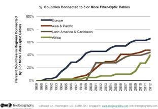

The 2nd key trend is increased competition across subsea systems. This is a direct result of more countries demanding to connect to more international fiber systems, preferably on shorter, higher performance routes and for the best possible prices.
The results are evident in customer demand for subsea upgrades that must be delivered in shorter intervals, with lower prices and demands for faster innovation. Many of those innovations will come in the form of advancements that will drive greater reach and capacity per fiber system, but will result in a better overall business case. Some of those technological innovations are discussed below.
Balancing system reach and capacity
Reach in subsea networks is highly dependent on the modulation format. Various modulation formats offer different values. Modulation formats such as QPSK transmit more power to reach further distance, but also require more fiber spectrum, as shown in Figure 1 below. By contrast 16QAM offers more capacity within the same spectrum, but is limited

requires the ability to choose the modulation format on-demand, on a per link basis. Programmable modulation changes the business paradigm and speeds deployment through the use of volume manufactured line cards, while also reducing the number of modulation specific spares. The provisioning model is also simplified, as it simply uses point and click to select the modulation format for the best Reach/Capacity for every link in the network, as shown in figure 2. This ability also enables redeployment of existing hardware or line modules on other parts of the network where a different modulation scheme would be more efficient.

super-channels also improve spectrum utilization by allowing tighter channel spacing and guard band elimination, resulting in more overall capacity from the fiber asset. Further, super-channels allow network engineers to keep pace with demand without increasing operational costs. Super-channel technology is tightly coupled with coherent modulation allowing the construction of superchannels that can be engineered for any reach dependent upon the proper modulation format chosen.
Other dependencies driving the evolution of super-channels include the extension of the current ITU DWDM fixed grid spacing (defined in ITU G.694.1), with a more flexible grid (ITU standard) to achieve even higher spectral efficiency, enabling a gain of up to 25% in net fiber capacity through more efficient spectrum use. An example of how 1 Tb/s super-channels may be implemented using both QPSK and 16QAM are show in figure 3.
Optimizing the overall subsea network
Super-channel technology
Super-channel technology is an evolution of DWDM technology in which several optical carriers are combined to create a composite line side signal of the desired capacity, and which is provisioned in one operational cycle. Beyond operations,

Figure 3
Commercial benefits of deploying super-channels is the deployment of pre-provisioned bandwidth. In effect, only one engineering/provisioning
Figure 1
Figure 2
cycle is initiated to deploy large chunks of network capacity. This eliminates network engineering and provisioning time associated with customer services, which can be upward of 60 days.
Coherent Technology
Complex modulation formats also require sophisticated receivers, also known as coherent receivers. Coherent receivers combine functions such as electronic compensation for accumulated chromatic dispersion, Forward Error Correction (Soft-Decision and Hard Decision) and other sophisticated algorithms to ensure proper reception of the high speed signal. Utilizing the combination of the programmable modulation and coherent reception, network operators can deploy a seamless network solution that operates over metro, long-haul and subsea networks
utilizing the same equipment, optimized for the appropriate location within the network. See figure 4.
Soft-Decision Forward Error Correction (SD-FEC)
Soft-decision forward error correction (SDFEC) for DWDM transmission systems is a recent innovation that enables the increase of capacity and reach of optical links. Unlike Hard Decision FEC, which chooses ones and zeros to make correction decisions, SD-FEC uses probabilities, resulting in significantly improved system performance. By combining high speed coherent transmission systems with SDFEC, significant coding gain can be achieved compared to Hard-decision forward error correction (HD-FEC). The tradeoff for this improvement is the requirement for higher overhead and hence high transmitted baud rates, which incur some transmission penalties. By optimizing the overhead, a 3dB coding gain can be achieved, effectively doubling reach when compared to enhanced FEC utilized in ITU G.709.
may also offer longer reach, the reverse is also true.
When combined with FlexCoherentTM Programmable Modulation formats SDFEC offers benefits enables the efficient tradeoff between capacity and reach. Existing fiber systems can benefit from an SD-FEC upgrade by increasing overall spectral efficiency. For example, an existing HD-FEC 100Gb/s BPSK signal may now be able to operate using QPSK with SD-FEC, effectively system doubling capacity in a given spectrum, while still maintaining, or even extending original reach targets.
Opportunities to Maximize Return on Investment (ROI)
Subsea networks have long been considered special, for a number of reasons. Amongst others, they may include the need to:

This is a critical feature that allows 100Gb/s subsea fiber systems to span Pacific Ocean distances. The coding gain is a trade-off against overhead, meaning a higher overhead which utilizes more spectrum
1) Operate in demanding circumstances, under the sea, repairable only by special ships
2) Be the primary lifeline for many remote countries
3) Operate in any environment including salt water, teething sharks and boat anchors
4) Must reach super long distances (10,000 km +)
It is these requirements that force subsea fiber systems to be built to exacting specs, tested and then re-tested to ensure they
Figure 4
work. In some cases the limitations have impacted performance, raised costs and extended delivery times of subsea network equipment. Until recently, the limited number of suppliers has been restricted to a few players. Today, the subsea market is split into ‘new’ providers and ‘upgrade’ providers. New providers being full turnkey cable deployment providers, and upgrade providers focusing on maximizing value from the existing wet plant. We will examine the ‘upgrade’ opportunities. While there are several areas for ROI improvement as part of a subsea upgrade, we will limit our examination to these three:
1) Subsea & Terrestrial network integration
2) Integrating DWDM and OTN Switching
3) Automated & Shared Mesh Protection
Opportunity #1 – Subsea/Terrestrial integration
A key value of leveraging terrestrial technology that is matched to subsea
systems is in integration. No longer are subsea networks required to sit on an island alone, with separate control and management. Instead, leveraging the coexistence of subsea and terrestrial transponders on the same common platforms in cable landing points, services can be provisioned from a terrestrial customer location anywhere on the network to a terrestrial location anywhere else, yet traversing a subsea network in between. The SLTE sites replace back to back transponders with full photonic integration reducing both power and footprint required without compromising on transmission performances typical in all-optical implementation, while also increasing reliability through the elimination of potential points of failure in between. See Figure 5. Further, through the use of control plane technologies like GMPLS control plane, the services can be provisioned on an end to end basis, even at the far end, as systems to provision all intermediate circuits. The value of this level of integration and control extends beyond equipment savings with operational savings as well.

Opportunity #2 – DWDM/Switching integration
Most subsea networks are built with predominance of simple point to point topologies. The challenge with this architecture is the fact that without a secondary aggregation device, such as muxponders or an external switch, many circuits are underutilized, resulting in lower overall network efficiency. The ability to integrate switching within the SLTE offers dynamic, on-demand add, moves and changes to the network allowing the network to operate at optimum capacity at all times. Infinera implements a technique known as Bandwidth VirtualizationTM enabling ondemand, hitless reconfiguration of large pools of capacity up to 500G. The addition of an integrated switch allows multiple client services to be switched and groomed onto a single network circuit at maximum efficiency. See Figure 6.
Opportunity #3 – Automated and Shared Mesh Protection
One of the most critical factors of the subsea infrastructure is the need for reliability. Not only are the subsea repairs challenging, the mission critical nature of the network cannot be underestimated. For example, the 2006 quake off southern Taiwan cut eight cables in 16 places, leaving China and southeast Asian internet users with no offshore connectivity for two days. It took more than a week to restore capacity and months to repair all the cables. (Source:
Figure 5

August 20, 2009 telecomasia.net) It is the nature of undersea cables that requires services to be protected in multiple ways. Methods of protection should hardware protection, multiple fiber protection and most importantly a mesh based network protection capability as defined by the ITU G.SMP.
Hardware level protection means that in the event of any type of system level failure, a redundant line card or alternate circuit path can be engaged. Services
level protection must consider all aspects of the service including the backhaul, the client port protection and service level management. But most importantly incorporating a mesh level protection that allows the network to seek any number of restoration routes in the event of a catastrophic event enables customers that have demanding reliability needs to be restored in times as fast as 50ms, by leveraging hardware based mesh restoration. See Figure 7.

terminal equipment to allow for shared or backup protection services. Since this process is both optimized and fully automated, network operators gain the value of full protection and SLA compliance with little extra expense, with even more upsell opportunities.
Maximizing the Return on Investment (ROI)
Leveraging many of the key technologies above will not only help drive greater network efficiency, longer reach and higher reliability, but also provide opportunities to increase ROI. However, maximizing ROI requires the right combination of the above technologies along with the network flexibility to adapt to your changing network and customer needs.
A further financial benefit is achieved by leveraging the integrated transport and switching functions within a single device, which eliminates the need for redundant
It is in this effort, that the value of photonic integration becomes critical. Photonic integration is proven technology that has been in operation over 750+ million hours without ever experiencing a field failure. Further, when it comes to combining the above referenced technologies into a high capacity transport and switching platform that does not compromise on either, photonic integration is the only way forward. For example coherent modulators and receivers, HD/SDFEC and integrated switching alone can overwhelm a single line card, much less a superchannel line card. See Figure 8.
In fact, with the benefit of miniaturization using Photonic Integrated Circuit (PIC) technology, multiple coherent
Figure 7
modulators/receivers, HD/SD-FEC and integrated switching can all be combined into a single line card that delivers up to 500 Gb/s super-channels today, scaling to 1Tb/s super-channels in the future. Further, photonic integration not only utilizes less space, but also consumes less power per Gb/s delivered.
Leveraging a subsea platform that consolidates multiple functions into small, high density, high reliability unit is only further enhanced with automated management and Generalized MultiProtocol Label Switching (GMPLS) control plane. GMPLS in an industry standard control plane technology that enable point and click service set-up, with the ability to establish and reconfigure Switched Network Connections (SNC) as needed to restore service operation.
Once SNC’s are established, the route
they traverse can be protected by predetermined or calculated, as determined by the network based upon the restoration requirements. Once SNC’s are established, they remain permanent unless there is a network change and the circuit is configured to be restored. Hardware based G.SMP (shared mesh protection) enables sub 50ms restoration, even for catastrophic failures. As shown in Figure 8.
It is this level of automation and reliability that will enable the future unmanned cable landing sites and further drive operational costs down, while increasing service capabilities and reliability overall.
Summary & Conclusions
Unlike their terrestrial counterparts, subsea networks remain special and demanding. The flurry of technological innovation including Photonic Integration, SoftDecision Forward Error Correction, FlexCoherent TM programmable coherent modulation, super-channels and Shared Mesh Protection (G.SMP) all provide critical benefits of improved fiber performance, maximum spectrum efficiency, ultra-
reliability and ultra-long reach which drive profitability and longevity of subsea networks.
Combining these innovations in a solution that ensures maximum reach and capacity, with the flexibility to select the right technology with robust reliability are critical to maximizing return on investment and ultimately enhancing the ‘serpent’ that transmits bits under the sea.


Vinay Rathore brings 20 years of telecom experience across a broad array of technology. He has helped some of the world’s largest companies including Sprint, Global One, MCI, Alcatel and Ciena build & market their newest products, technologies and services. Mr. Rathore’s area of expertise includes network engineering, operations, sales & marketing in both wireline and wireless systems as well as leading edge network solutions spanning Layer 0 to Layer 3. Mr. Rathore holds a degree in Electrical Engineering from Virginia Polytechnic Institute as well as an MBA from the University of Texas.
Figure 8
The Undersea Cable Report 2013
From Terabit Consulting Publication Date: September, 2012 Intelligent intelligencego beyond the numbers!

The most diligent quantitative and qualitative analysis of the undersea cable market - 1,600 pages of data, intelligence, and forecasts that can be found nowhere else.
Terabit Consulting analysts led by Director of International Research Michael Ruddy tell you what’s real and what’s not, where we’ve been and where we’re headed.
The Undersea Cable Report capitalizes on Terabit Consulting’s global on-site experience working with carriers, cable operators, financiers, and governments in over 70 countries on dozens of leading projects (e.g. AJC, BRICS, EASSy, Hibernia, SEAS, TBI)a world of experience, at your fingertips in a single resource!

YOUR KEY TO UNDERSTANDING AND HARNESSING
THE $20 BILLION UNDERSEA MARKET OPPORTUNITY

• Ownership, system supply, financing, and project costs
valuable intelligence • innovative modeling • thoughtful insight • global perspective
respected expertise

Satellite Backhaul: The Fibre Alternative
James Barton
The term ‘cellular backhaul’ covers more now than it did two or three years ago, encompassing a far broader range of technologies that have become more widespread, including internet services offered by digital devices as well as remote or maritime communications facilitated by small cells.
Fibre is often thought of as the go-to technology for backhauling, but it isn’t always an option – particularly in emerging regions such as Africa and Latin America, where there simply isn’t enough fibre in the ground. Markets that are undergoing extensive growth can often run into this problem, and it is in these situations that satellite backhaul becomes a financially viable alternative.
In areas that are lacking in fibre infrastructure, satellite backhaul has numerous advantages over competing technologies such as microwave, according to David Furstenburg of Novelsat, who points to the area of disaster relief as an example. Citing the 2011 Japanese tsunami, he notes that of the four active and four backup cables that connected Japan to the USA, six were rendered unusable following the disaster.
“There is no other system that will have the resilience of satellite, but there are two major challenges with the technology: cost and delay. These are the drawbacks, but there are a number of ways to overcome them”, says Furstenburg.
Across the satellite industry, Ka-band services are becoming increasingly common as they significantly lower the cost of band-
width. In addition, the use of inclined orbits is becoming more widespread, particularly in emerging markets.
Satellites typically have a 15-year lifespan, and towards the end of this its orbit will become less stable; to use the service there must be a tracking mechanism from the antenna that follows the satellite so that the intensity of the signal doesn’t drop.
Satellites with inclined orbits typically command far lower prices than newer satellites; a trial conducted by Novelsat and SES found that it was possible to compete with reduced-cost fibre in Africa via a combination of a high-reliability modem and inclined orbit satellites. By adding in a capacity multiplier, it becomes possible to reduce prices from around $3000 a month to just $1000.
By reducing the costs of backhauling, it is possible to transfer the savings to the end user, and – particularly in emerging markets – this typically results in massive uptake. As soon as more people adopt the service, it starts a cycle of cost reduction.
“I believe that using the Ka-Band will drop prices dramatically”, says Furstenburg. “The only enabler that it will need to win rural internet customers is the data rate that those customers are demanding.”
The DVB-S2 satellite standard was widely believed to be so close to its physical limit that it could not be improved in a significant way; this resulted in the entire industry shifting its focus towards improved compression. Data rates are key, according to Furstenburg – providing reliable, fast internet to rural consumers will require around 1Gbps, which has not yet been achieved.
“At the end of the day, we’re a bunch of plumbers providing pipes”, he says. “What arrives through the pipe is down to the consumer. The major impact of the technology is to reduce the cost of ownership to the operator, thereby enabling lower cost services to the end user.”
This article reprinted from:


Coming Soon
To A Wall Near You
2013
Submarine Telecoms Industry Calendar


Back Reflection

by Stewart Ash
Lumps and Bumps
One of the major design challenges for a modern DWDM fibre optic submarine cable system is ensuring that end to end transmission performance is the same for each wavelength. The attenuation of fibre differs slightly with each wavelength as does the gain of optical amplifiers and, due to manufacturing tolerances, no amplifier or piece of fibre is exactly the same as another. These small differences are cumulative along a system and so it becomes essential to equalise the discrepancies, either at the Terminal Station or, for trans-oceanic systems, in the submerged plant. This need for equalisation is not a modern requirement, during the Telephone Era (1950 -1986), wideband equalisation was standard practice and it was a far more complex task than today’s optical equalisation.
To illustrate this, we will consider perhaps the most successful, in terms of sales, submarine telephone cable system ever and
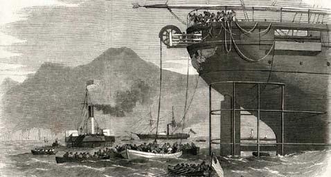
how its manufactures went about system equalisation. The system in question was the STC Submarine Systems (now AlcatelLucent Submarine Networks) 14Mhz System. The system design was based on a 1.47” (37.34mm) diameter, coaxial cable with a characteristic impedance of 54.4Ω; repeaters, to compensate for the signal loss in the cable, were spaced at regular intervals along the cable. Each repeater contained power separation filters to separate the transmission signals from the DC power and directional filters to divide the transmission path into Low Band (0.3 – 6.00MHz) and High Band (8.00 –13.7MHz).
The attenuation, or power loss, of a coaxial cable is proportional to the frequency of the signal transmitted; the 14MHz system was designed such that, for each repeater span, the cable had an attenuation of 45dB at the highest operating frequency of 13.7MHz, under sea bed conditions. This resulted in a nominal repeater spacing of 6.5nm (12.06km). Under sea bed conditions is an
important statement because, unlike fibre optic cable, the attenuation of coaxial cable changes with temperature and hydrostatic pressure. This meant that cable sections were manufactured to a specific length in order to have the correct attenuation in a particular location on the sea bed at a specific water depth and sea bottom temperature.
The repeater amplifiers were designed to compensate for the loss of the cable plus the loss of the repeater filters. Of course, it was impossible to make the gain shape of the amplifiers exactly match these losses and, due to manufacturing tolerances, each repeater’s overall performance was unique. This meant that cumulative, frequency dependent differences developed, section by section, along the system. The repeater also introduced a secondary transmission problem. In order to joint the 1.47” (37.34mm) cable to the repeater, the cable had to be tapered down to a 0.310 (7.87mm) diameter tail cable that had a braided outer screen. This
tapered termination and the repeater itself provided a discontinuity or “mismatch” in the transmission line impedance. When an electrical signal propagates along a transmission line if it encounters a mismatch a small amount of the signal is reflected back down the transmission line. This occurs at the cable repeater interface and the reflected signal travels back along the cable, being attenuated, until it reaches the earlier repeater and once again a small part of the reflected signal is re-reflected along the cable in the same direction as the primary signal. It depends on the phase relationship between the original signal and the double reflected signal as to whether they add or subtract. This phase relationship will be slightly different at each frequency and so this phenomenon produces an effect called “mismatch ripple”. To prevent the build-up of mismatch ripple the lengths of the repeater sections were offset from the nominal in a predetermined pattern.
To deal with these variations in transmission performance, submerged Equalisers were introduced into the system. For the 14MHz this was every 15 repeaters or approximately every 100nm (185.53km) of cable. The repeater section between repeaters 15 and 16 was reduced by an amount of cable equivalent to 13dB of attenuation at 13.7MHz. The Equaliser was placed mid-section between two nominal 2.3nm (4.27km) lengths of cable. Once again, for long systems, mismatch ripple in the Equaliser sections had to
be taken into consideration. Because of the shorter cable lengths between the Equaliser and the Repeater, reflected signals were attenuated less and so the mismatch ripple could be of much greater magnitude. To counteract this problem the position of each Equaliser, between the repeaters, would be offset from the nominal in a predetermined pattern. Although these short Equaliser sections made available 13dB of excess gain at 13.7MHz, the attenuation of coaxial cable at lower frequencies is much less and at the bottom of the Low Band there was insufficient excess gain to allow any useful equalisation. This problem was overcome by designing the Low Band amplifier to over compensate for the cable losses and so build excess gain over the 15 repeater sections to make available sufficient excess gain for useful equalisation.
What has been described so far are the engineering issues that all of the submarine cable manufactures had to address; however, how STC Submarine Systems differed from the other suppliers is how it went about carrying out the necessary system equalisation.
To equalise a system effectively it is necessary to predict its performance on the sea bed, this can be done by measuring the performance of individual cable sections and repeaters in the factory, add the results together and then applying mathematical formulae to predict performance on the sea bed. It should
be noted that during the Telephone Era, cable sections and repeaters were only joined together during the loading of the cable ship i.e. System Assembly and Test (SAT) was carried out on the cable ship not in the cable factory. AT&T, Alcatel, Fujitsu and NEC took this approach; they measured the individual components, did the calculations, produced a predicted performance and then designed and built each Equaliser in the factory. For a period AT&T introduced some flexibility into its equalisation capability by building an Equaliser that had a limited number of circuits that could be switched into the transmission path during the lay by the use of a complicated system of external magnets that moved ball bearings within the Equaliser housing.
STC took a different approach, its Equaliser housing could be opened and closed on the cable ship, thus giving access to the transmission path at each Equaliser and allowing unique passive circuits made from Inductors (L), Capacitors (C) and Resistors (R) to be designed for each Equaliser. Each Equaliser did contain a standard, factory built Equaliser to address the main, known discrepancies. This Equaliser was designed to leave a nominal flat 4dB of excess gain across both bands with an additional cable shaped gain of 3dB @ 13.7MHz, available for shipboard equalisation.
During the laying operation, transmission tests of the system were made between
the Equaliser test point on the cable ship and the terminal station. The results of these tests were then operated on to predict system performance when the whole Equaliser block (15 repeaters) had been laid. This prediction was called the “Equaliser Requirement”. To do this it was necessary to know the, length of cable already laid, the length of cable yet to be laid, the number of repeaters laid and yet to be laid, the temperature of the cable and repeaters on the ship and the water depth and temperature of the sections of cable still to be laid. When tests were carried out, at any point in laying of the block, there would be a percentage of cable and repeaters on the sea bed, another percentage on the ship and, depending on the water depth, a small amount in transit between the two (the laying catenary). In deep water the catenary could be up to 20nm (37.11km) in length. Factors that had to be taken into account were the temperature and pressure coefficients of the cable, the effects of temperature and pressure changes on the 0.310” (7.87mm) termination as well as its change in characteristic impedance when it was immersed in water. All these cable affects had a short time constant of 10 -15 minutes. The repeaters also had a small but finite temperature coefficient which had to be taken into consideration. When powered the internal temperature of the repeater was 5 – 6°C above ambient. Repeaters could be at an ambient of 25 – 30°C on the ship in deep water the sea bed temperature could be 2°C. It took
some time for the internal temperature of the repeater to adjust to ambient as the pressure house created a thermal lag of some 6-8 hours.
As can be seen, at the beginning of laying an Equaliser block, the Equaliser Requirement was only a small percentage actual performance and over 90% prediction. However, as laying progresses the amount of prediction decreased. To ensure that predictions were accurate, graphs of the Equaliser Requirement, at 6 – 8 frequencies in each band were plotted against the amount of cable laid. If all was well the prediction for each frequency would remain the same and the graphs parallel to the X axis. However, if there were errors in any of the assumptions then the graphs would slope up or down. This slope could then be extrapolated to as laid position and the differences taken into account in the final Equaliser design.
The individual LCR circuits were designed, manufactured in clean area conditions and tested individually. Then all the circuits were inserted into the Equaliser and tests made through them to the terminal station. These final tests were then converted to an Equaliser Requirement before the Equaliser was closed and pressurised. The target was to have a final Equaliser Requirement of 0.00dB, at all frequencies within the transmission bands, by smoothing out all the lumps and bumps, eliminating any steep slopes and achieving an overall performance within
±0.5dB and a maximum deviation from 0.00dB no greater than 1.0dB. This target was regularly achieved.
In order for the cable ship to plan and maintain a steady laying speed, the transmission and Equaliser design team worked to a strict 18 hour design schedule. In the first 14 hours detailed transmission measurements were carried, the necessary LCR circuits were designed built and tested then, the LCR circuits were inserted into the Equaliser which was then closed and pressurised. This last process took 2-3hours and this was scheduled to be completed 1 hour before the Equaliser was due to be laid. This strict schedule was maintained from one Equaliser to the next throughout the lay. The steady laying speed was essential for accurate cable placement at a time when slack control was based on taut wire and limited GPS coverage.
Today, system equalisation can be carried out in the factory, during SAT, as there are no significant laying affects to be taken into consideration. The system performance in the factory will be very similar to its performance once installed, so shipboard system equalisation is another skill/black art that has been consigned to the history books.

SUBMIT YOUR FREE LISTING

Including nearly 150 individual companies, this Directory serves as an invaluable tool for anyone looking to familiarize themselves with the submarine industry. The directory is detailed by 11 distinct categories of submarine fiber businesses, from analysts to legal support and cable planners to cable suppliers.
Conferences

PTC'13
20-23 January 2013
Honolulu, USA
Website
SubOptic 2013
22-25 April 2013
Paris, France
Website
ICPC
21-23 May 2013
Miami, USA
Website
Submarine Cable Forum
4-5 November 2013
Miami, USA
Website
January:
March:
May:
July:
September: Offshore
November:
Advertising enquiries: SALES MANAGER
Kristian Nielsen
Tel: +1 (703) 444-0845
Email: knielsen@subtelforum.com


by Kevin G. Summers
SubTel Forum has the best readers.
I'm not saying that to flatter you or to encourage you to buy advertising. It's my way of saying thank you.
As you are probably aware, we released the fourth issue of our Submarine Cable Almanac last week. If you've read it, you can imagine the countless hours of research that went into the book. Mistakes, unfortunately, are made. That's when our readers step up.
I want to thank Stewart Ash, Derek Cassidy, Willy Davidson, Martha Etsibah, John Hibbard, Takashi Kodama, Larry Schwartz, Ras Scollay, Horace Sookdeo, and Christian von der Ropp for submitting corrections to previous editions of our Almanac, and John McLean and Petroc Wilton for submitting changes after the release of Issue 4. These
changes will be incorporated into our next edition, due early next year.
Did you see an error in the Almanac? What about on our Submarine Cable Map? While we may seem superhuman here at SubTel Forum, we do make mistakes. If you find one, please contact me and I will see that it is fixed.
As always, thanks for reading.


