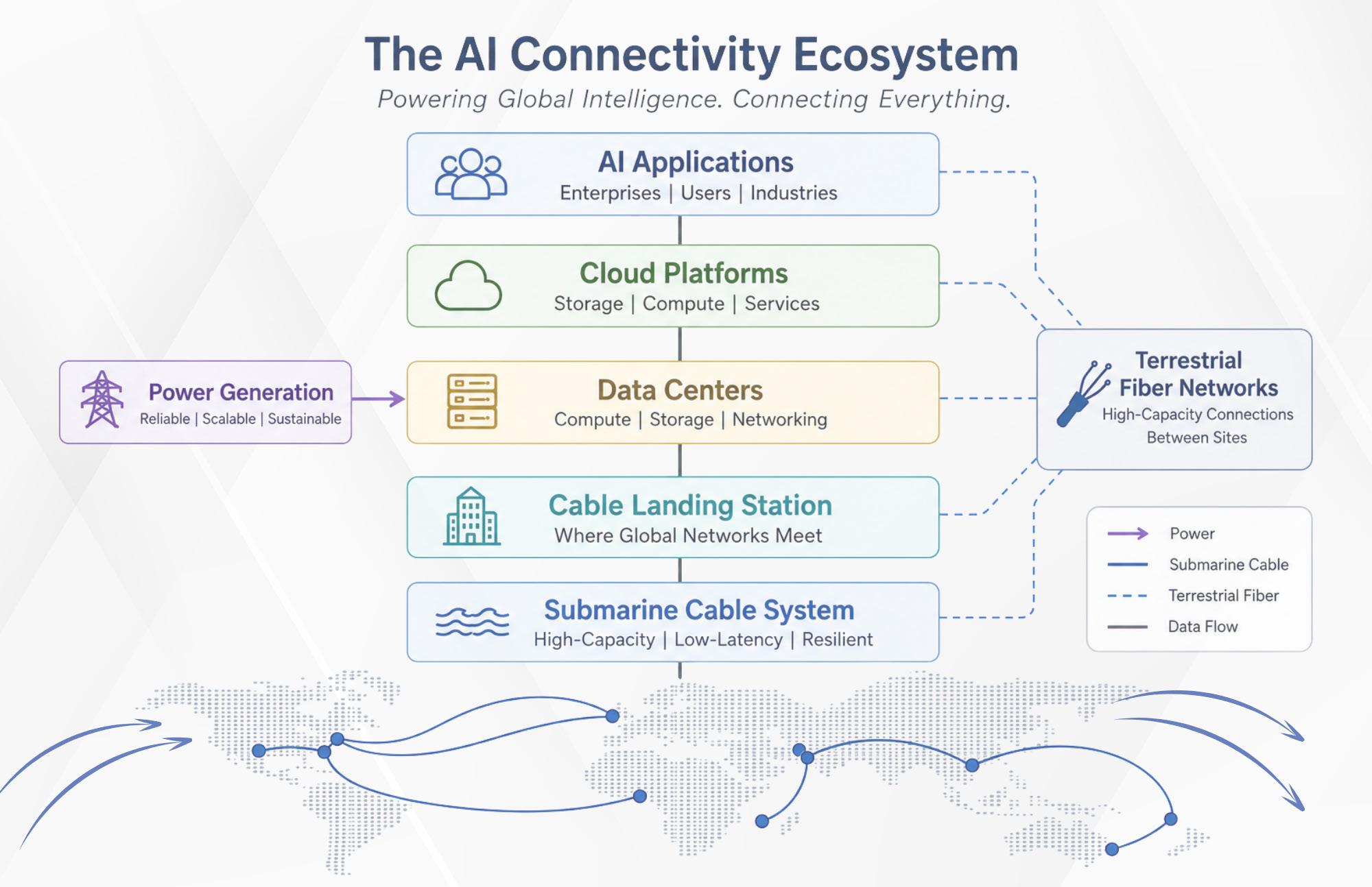
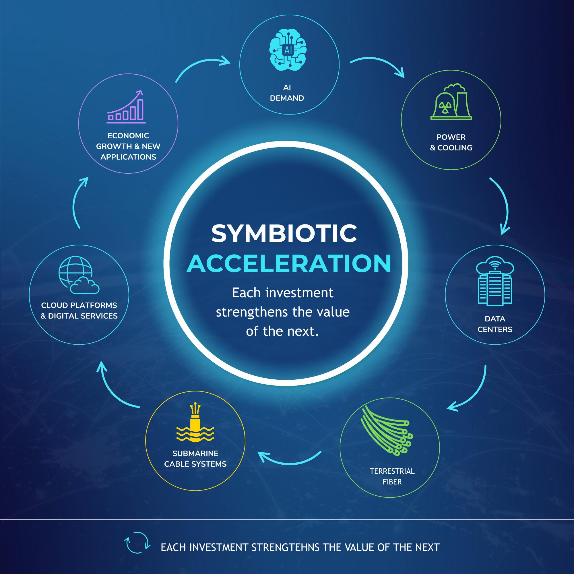
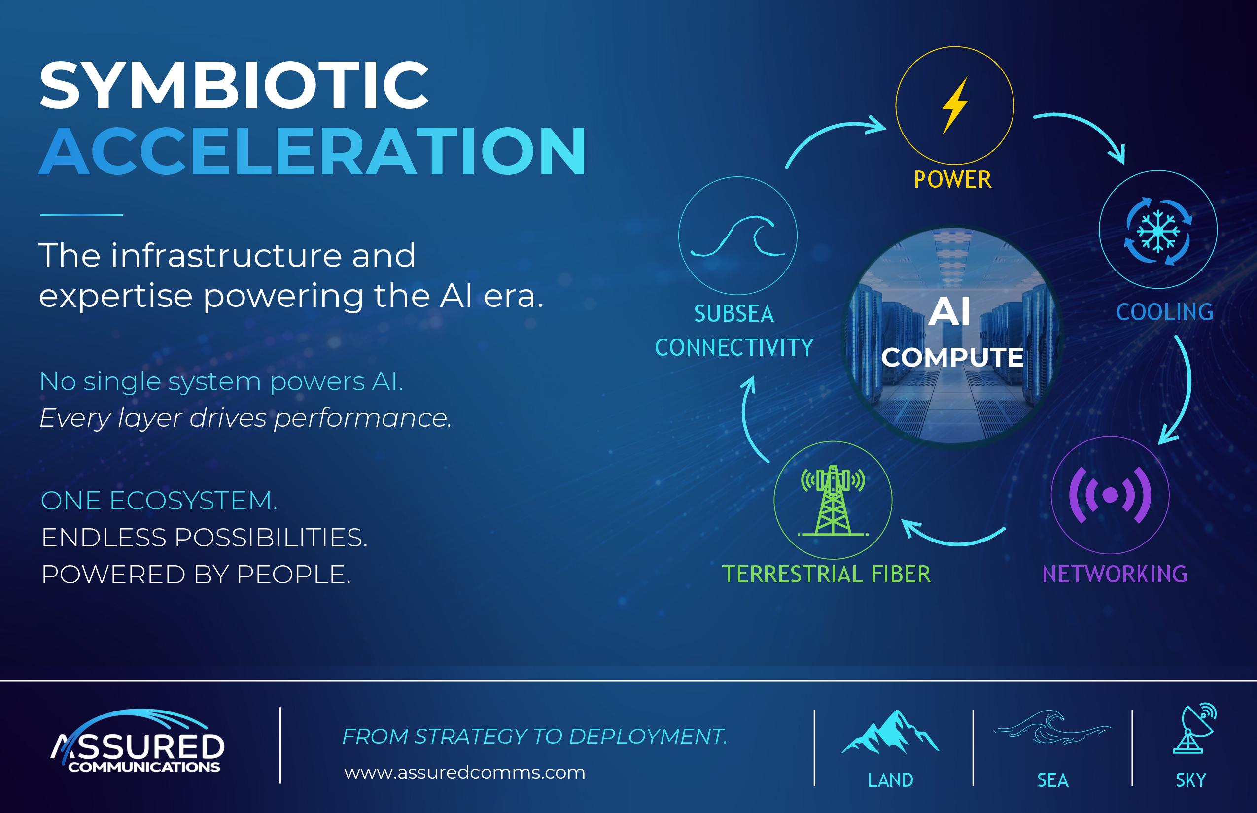
SYMBIOTIC ACCELERATION: WHY CONNECTIVITY IS BECOMING AS IMPORTANT AS POWER IN THE AI ERA
Powering AI through connected digital infrastructure by Joel Ogren
56
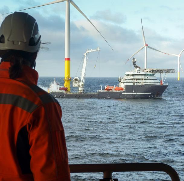
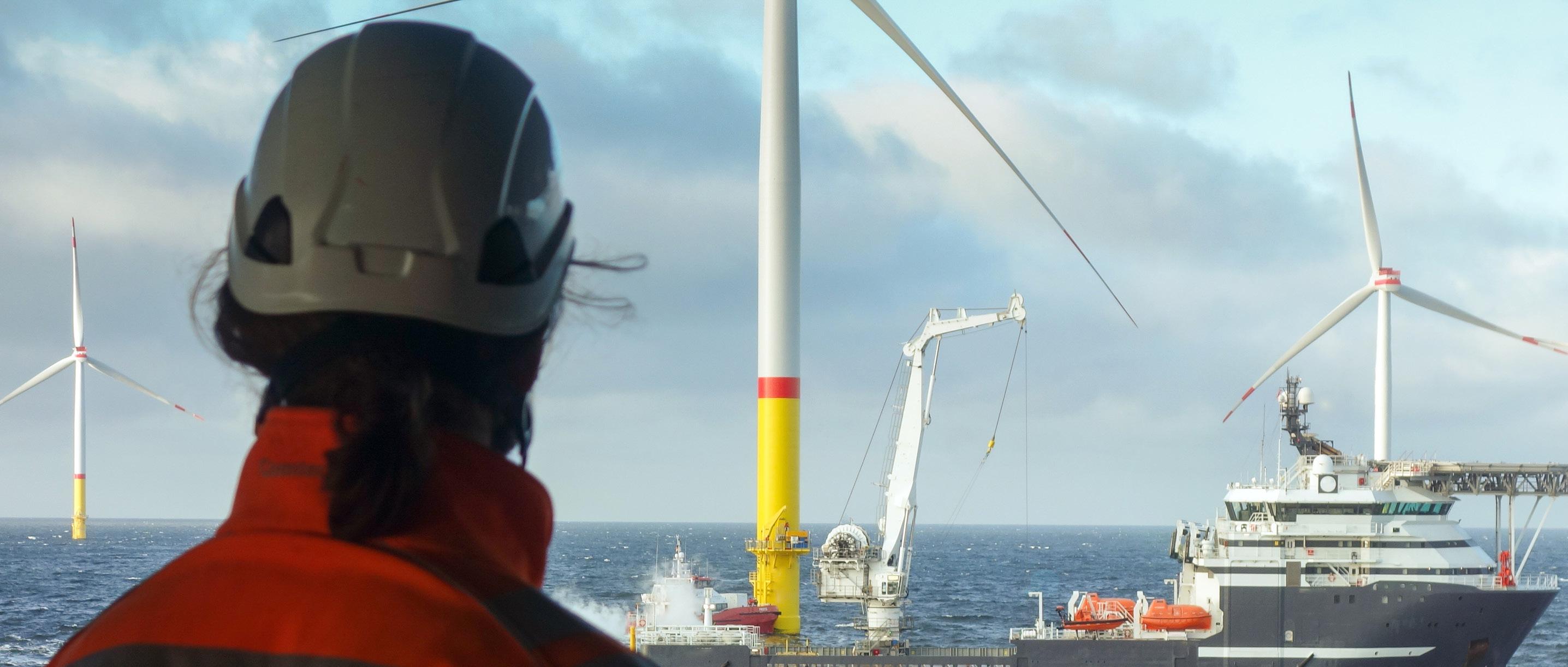
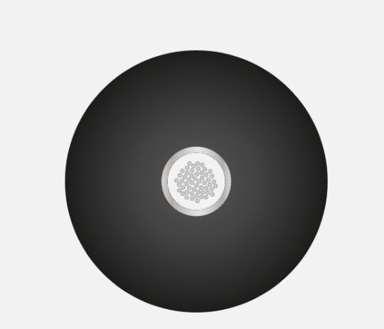
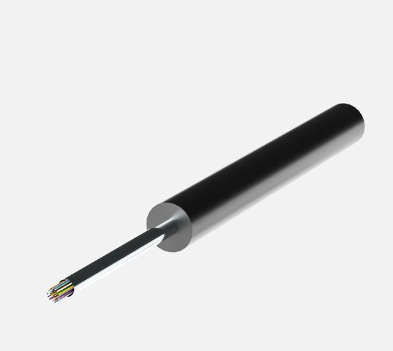
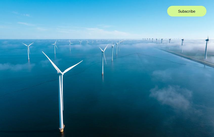
INTEGRATED FIBER OPTICS: SUPPORTING SUSTAINABLE ENERGY, OFFSHORE WIND AND THE GLOBAL TRANSITION TO RENEWABLES
Integrating fiber optics into offshore power cables by Tobias Borg
60
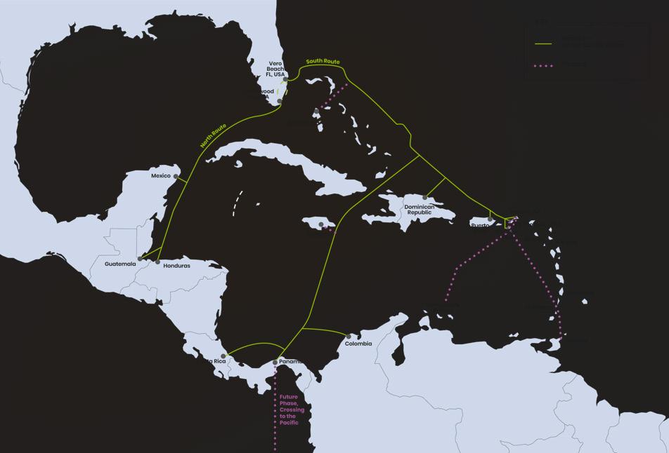
TAM 1: REDEFINING REGIONAL CONNECTIVITY ACROSS THE AMERICAS
Redefining Caribbean connectivity through regional integration by Alasdair Wilkie 64
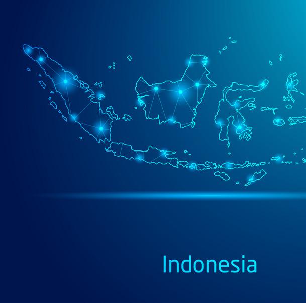
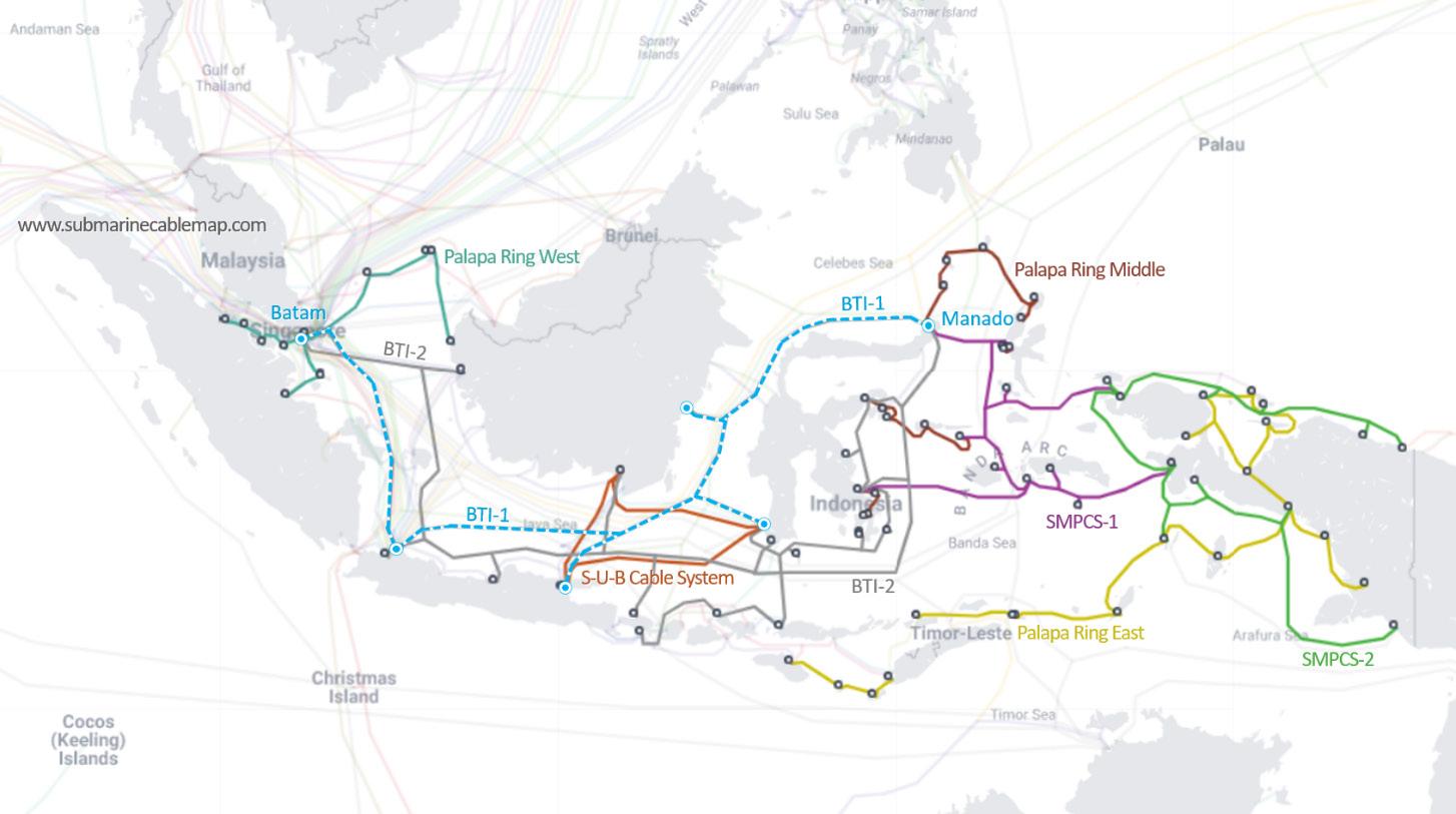
CLEARER WATERS: INDONESIA CONSOLIDATES THE GOVERNANCE OF REGIONAL CABLE SYSTEMS
Streamlining Indonesia's submarine cable governance by Marshall Jahja
FROM SEABED TO SERVICE: COMMERCIALISING A NEW SUBMARINE CABLE IN SMALL AND DEVELOPING COUNTRIES
Commercializing submarine cables for developing nations by Paul McCann, John Hibbard
74
REGIONAL SUBSEA SYSTEMS: ENABLING RESILIENCE VALUE IN THE DIGITAL ECONOMY
Building resilience through regional subsea diversity by Daniele Silva
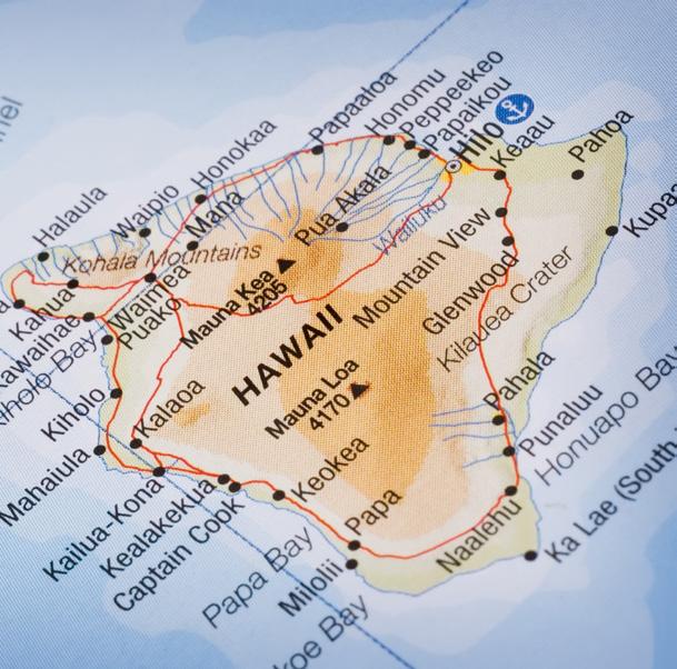
HAWAIIAN ISLANDS FIBER LINK (HIFL): STRENGTHENING HAWAIʻI’S DIGITAL FUTURE THROUGH REGIONAL SUBMARINE CONNECTIVITY
84
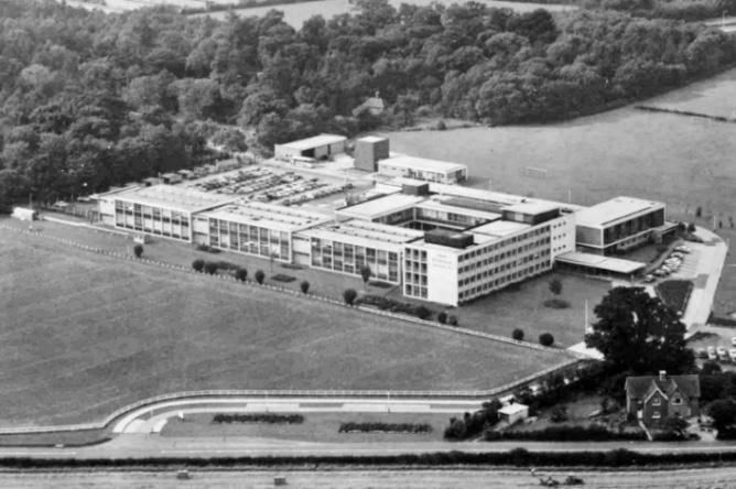
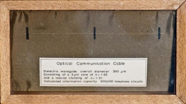
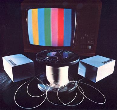
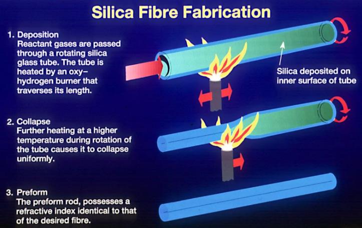
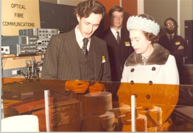
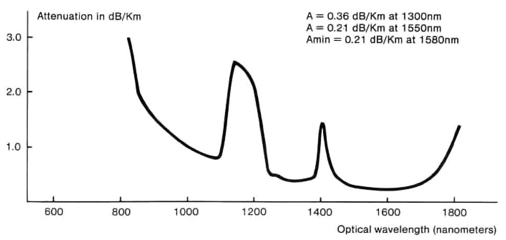
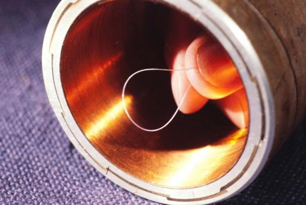
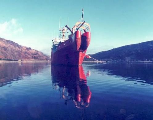
THE BIRTH OF OPTICAL FIBRE COMMUNICATIONS: A VERY BRITISH STORY
Tracing Britain's optical fiber communications revolution by Stewart Ash, Stuart Barnes, Phil Black, Bill Burns, Chris Swan
Strengthening Hawaiʻi through resilient island connectivity by Cliff Miyake 44
98 FROM MAXWELL’S EQUATIONS TO SUBSEA FIBRE OPTICS (PART 3)
Exploring optical physics shaping future subsea networks by Anna Bridget Sheehan, Derek Cassidy
96
WHEN SUBSEA CABLES FAIL, REPAIR COORDINATION BECOMES THE REAL FAULT LINE
Improving cross-border coordination for faster repairs by Gaya Byrne
CONFERENCE PREVIEW
6 QUESTIONS WITH ADAM BALL
Talking Submarine Cable Industry and Security with Terrapinn’s General Manager
48
AGENDA
Bringing infrastructure, policy, and investment leaders together.
INSIDE SUBTEL FORUM:
25 Years of Submarine Cable Intelligence
In 2026, SubTel Forum marks 25 years as the leading independent intelligence platform serving the global submarine cable industry. Over a quarter century, SubTel Forum has evolved from a specialist publication into the industry’s most trusted source for data, analysis, mapping, and editorial insight. SubTelForum.com now stands as the central reference point for operators, suppliers, investors, governments, and advisors shaping global connectivity.
What follows is a guide to SubTel Forum’s most important products and resources for 2026.
IN DEPTH INDUSTRY PUBLICATIONS
At the core of SubTel Forum are its flagship publications, which define how the industry understands itself.
Submarine Telecoms Industry Report (Annual)
The industry’s benchmark analytical report. Each edition delivers rigorous assessment of market
structure, ownership trends, capacity growth, investment drivers, and forward outlooks. It remains essential reading for executives and policymakers navigating an increasingly strategic infrastructure sector.
Submarine Cable Almanac (Biannual)
A data driven reference providing detailed system level coverage of global submarine cable networks. Each biannual edition includes maps and structured data on routes, capacity, ownership, status, and technical attributes. It is one of the most frequently cited resources in the industry.
Cableship Codex (Biannual, Launching 2026)
New in 2026, Cableship Codex is a biannual intelligence product focused exclusively on the global cable ship fleet. It delivers authoritative coverage of vessels, ownership, technical capability, utilization trends, and market dynamics. For the first time, the industry gains a structured, recurring reference
dedicated to the assets that build and maintain global subsea infrastructure.
CABLE MAPS AND VISUALIZATION TOOLS
Online SubTel Cable Map
An interactive digital platform mapping more than 600 submarine cable systems worldwide. It supports research, planning, and analysis through an intuitive interface designed for professionals.
Printed Submarine Cable Map
The definitive physical reference of global submarine fiber infrastructure. Updated and reprinted multiple times each year for distribution at key industry conferences, it reflects the latest system developments and is widely displayed in offices, boardrooms, and event venues across the global subsea sector.
SubTelForum.com Directory
The SubTel Forum Directory is the industry’s most comprehensive free listing of vetted submarine cable companies, service providers, and specialists. Designed for speed and clarity, it enables practical commercial discovery and strengthens community connectivity across the ecosystem.
NEWS AND DAILY INTELLIGENCE
News Now RSS Feed
The daily pulse of the submarine cable industry. News Now curates global coverage spanning projects, outages, regulation, technology, and geopolitics. It is a core tool for staying informed in a fast moving sector.
SubTel Forum App
The SubTel Forum App continues to mature in 2026 as a primary mobile access point. It integrates news, editorial content, data driven insights, and alerts into a streamlined experience built for real time awareness and professional use.
EDITORIAL KNOWLEDGE HUB
Must Reads and Q&As
A curated collection of long form articles, interviews, and expert discussions exploring the technical, commercial, historical, and strategic dimensions
of submarine communications.
Magazine Archive
Spanning more than 25 years, the Submarine Telecoms Forum Magazine Archive offers an unmatched historical record of the industry’s evolution. It serves as a living institutional memory for researchers, analysts, and practitioners.
Authors Index
The Authors Index enables readers to locate articles by contributor and follow the work of leading industry voices, reinforcing SubTel Forum’s role as the platform of record for submarine cable thought leadership.
Bespoke and Special Reports
SubTel Forum produces tailored reports addressing specific market needs, including Global Outlook analyses, data center and OTT studies, offshore energy connectivity, regional systems assessments, unrepeatered systems reviews, and comprehensive cable datasets covering more than 550 systems.
After 25 years, SubTelForum.com remains the industry’s most complete and trusted intelligence platform. Built on continuity, independence, and execution discipline, it continues to support those designing, financing, building, and operating the infrastructure that connects the world.
EXORDIUM
Welcome to Issue 149 of SubTel Forum, our Regional Systems edition, featuring a preview of Submarine Networks World 2026.
If it’s July, it must be time for the world’s toughest endurance event—the Tour de France!
Like a regional cable system, it demands planning, resilience, teamwork, and the ability to overcome difficult terrain. This issue explores the technologies, policies, and partnerships expanding regional connectivity worldwide. Enjoy the ride.
SEARCH – DISCOVER – CONNECT
We’ve enhanced key SubTel Forum resources, making it easier to discover content, connect with experts, and find leading industry companies.
1. The updated Article Index turns more than two decades of SubTel Forum content into a searchable knowledge base organized by author, title, topic, publication, and keyword.
2. The new Author Index features more than 800 contributors and provides direct access to 2,036 articles, 410 company profiles, and 148 magazine issues.
3. Each Author Profile presents a contributor’s biography, expertise, photograph, and published articles in one place, helping readers learn more about the experts behind the content.
4. The updated Company Directory helps users quickly find companies, products, services, suppliers, and industry partners by category, keyword, or company.
INSIDE ISSUE 149: BUILDING REGIONAL CONNECTIVITY FOR A DIGITAL FUTURE
This issue examines regional systems and policies shaping tomorrow’s digital infrastructure, including offshore energy connectivity, Caribbean and Hawaiian network development, AI-driven infrastructure, Indonesia’s cable governance, resilience, commercialization, repair coordination, optical fiber communications, sustainability, permitting, legal developments, and the strategic role of regional networks.
WELCOME TO PERMITTING PATHWAYS
We are pleased to welcome Anjali Sugadev as the author of our newest column, Permitting Pathways. Drawing on her experience in permitting and environmental compliance, Anjali will examine the regulatory challenges and opportunities shaping the global subsea industry. Welcome aboard, Anjali!
PAYING THE BILLS
Please welcome Hannah Schiffman of Association Media Group as SubTel Forum’s new advertising sales representative. She will also author Advertiser’s Corner, sharing marketing insights, advertising opportunities, and ways companies can strengthen their industry visibility.
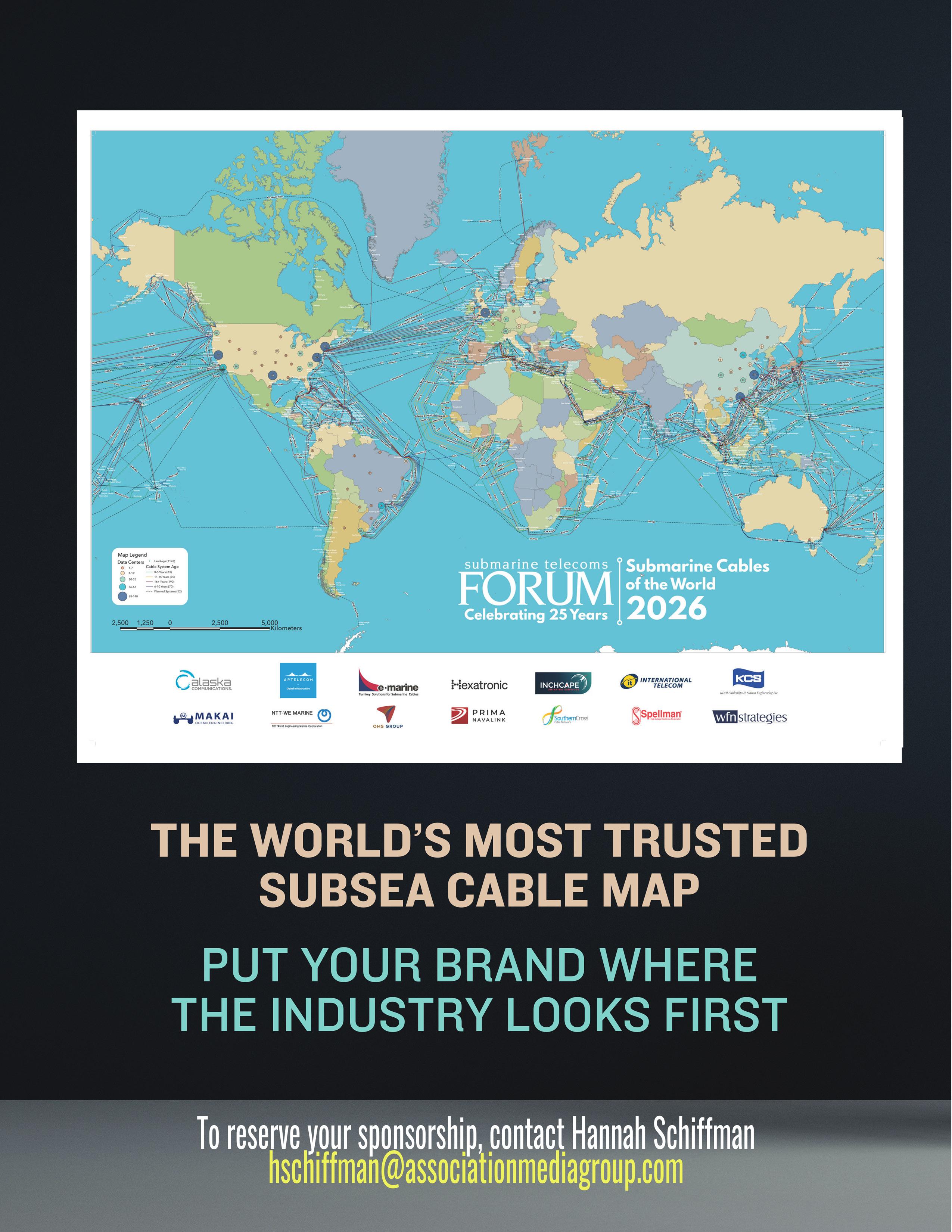
CABLE MAP – SUBMARINE NETWORKS WORLD 2026
As the industry gathers in Singapore for Submarine Networks World 2026 this September, SubTel Forum will publish the latest Submarine Cables of the World wall map, a recognized industry visual reference. Contact Hannah Schiffman to secure your spot!
ALMANAC – AUGUST 2026
This August, SubTel Forum will publish the latest Submarine Cable Almanac, the industry’s trusted reference for global cable system data, ownership, suppliers, and market intelligence. Advertising opportunities are available; to reserve space, contact Hannah Schiffman.
Thank You!
Our thanks go to our outstanding authors, with special appreciation to this issue’s advertisers: ACS, Assured Communications, APTelecom, Fígoli Consulting, Hexatronic, Southern Cross, and WFN Strategies.
And don’t miss our perennial reader favorite, Where in the World Are All Those Pesky Cableships?
Enjoy the issue and le Tour, and as always—Slava Ukraini!
Wayne Nielsen is the founder and publisher of Submarine Telecoms Forum, one of the industry’s most trusted intelligence platforms, reaching more than 150,000 readers in 115 countries. He is also Managing Director of WFN Strategies, with over 35 years of global submarine cable experience spanning commercial, governmental, and offshore energy systems.
Contributions from SubTel Forum editorial staff and industry experts including Adam Ball, Derek Cassidy, Kieran Clark, Andrés Fígoli, John Maguire, Nick Morris, Kristian Nielsen, Wayne Nielsen, Andrew Parsons, Phillip Pilgrim, Hannah Schiffman, and Anjali Sugadev
Feature Writers
Stewart Ash, Stuart Barnes, Phil Black, Bill Burns, Gaya Byrne, Derek Cassidy, John Hibbard, Marshall Jahja, Tobias Borg, Paul McCann, Cliff Miyake, Joel Ogren, Anna Bridget Sheehan, Daniele Silva, Chris Swan, and Alasdair Wilkie
NEXT ISSUE
September 2026 – Offshore Energy featuring International Wire & Cable Symposium 2026
Article Index subtelforum.com/article-index/ Author Index subtelforum.com/authors-index
Wayne Nielsen, Margaret Nielsen, Kristian Nielsen and Kacy Nielsen Corporate information: subtelforum.com/corporate-information
SUBMISSIONS
Contributions are welcomed and should be submitted to: pressroom@subtelforum.com
PUBLISHING AND LIABILITY NOTICE
Submarine Telecoms Forum magazine is published bimonthly by Submarine Telecoms Forum, Inc. It is an independent commercial publication serving as a freely accessible forum for professionals engaged in submarine cable systems and global digital infrastructure. No part of this publication may be reproduced or transmitted in any form, in whole or in part, without prior written permission from the publisher.
SUBSCRIPTIONS AND ENQUIRIES
Submarine Telecoms Forum, Inc. | 19471 Youngs Cliff Road, Suite 100 | Sterling, Virginia 20165 USA | Phone: +1 703 861 3647 | Website: www.subtelforum.com
While every effort is made to ensure accuracy, the publisher accepts no liability for errors or omissions in editorial or advertising content, or for any consequences arising therefrom. The editor reserves the right to edit all submitted material.
MAPPING THE WORLD’S SUBMARINE CABLE INFRASTRUCTURE
by Kieran Clark
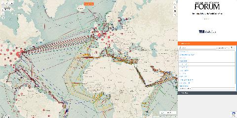
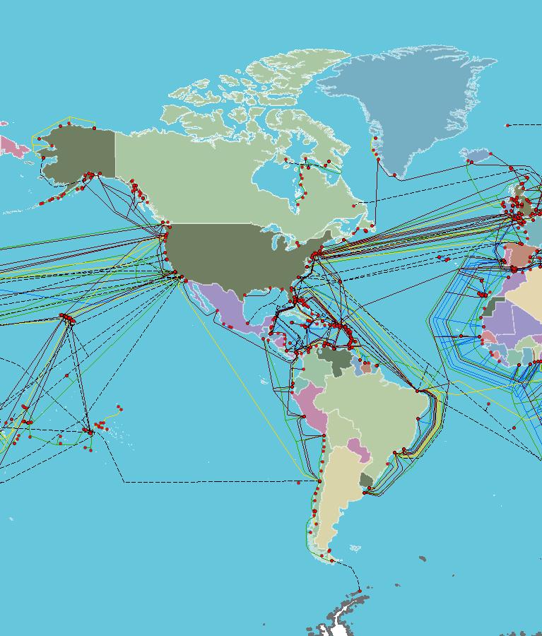
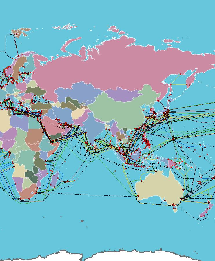
The SubTel Cable Map—powered by Esri’s ArcGIS platform—offers an interactive and detailed way to explore the global network of submarine cables.
This indispensable resource provides information on over 440 existing and planned systems, more than 50 cable ships, and upwards of 1,100 landing points. Connected directly to the SubTel Forum Submarine Cable Database and integrated with our News Now Feed, the map enables real-time tracking of industry activity and cable-specific news coverage.
Submarine cables serve as the foundation of global digital infrastructure, carrying more than 99% of international data traffic. These systems enable the seamless connectivity the world depends on—from personal communication to enterprise operations. Without them, modern, high-speed global communication simply wouldn’t be feasible.
Our analysts continually update the map using verified data from the Submarine Cable Almanac and valuable input from industry contributors. This ensures a timely and accurate picture of the subsea cable landscape, spotlighting the latest deployments and developments. As we approach the end of the year, map updates may slow during the holiday season, but our commitment to delivering reliable insights remains unchanged.
We’re proud to feature WFN Strategies as the current sponsors of the SubTel Cable Map. Additional sponsorship opportunities are available—offering high-visibility placement for your logo and a direct link to your organization. It’s a great way to align your brand with global connectivity and the future of the submarine cable industry.
We invite you to explore the SubTel Cable Map and gain a deeper understanding of the vital role submarine cable systems play in our interconnected world. As always, if you are a point of contact for a system or company that requires updates, please email kclark@subtelforum.com.
We hope the SubTel Cable Map proves to be a valuable resource for you, offering insight into the continually evolving submarine cable industry. Dive into the intricate network that powers our global communications today. Happy exploring!
Kieran Clark is Senior Analyst at Submarine Telecoms Forum, Inc. He joined in 2013 as a Broadcast Technician supporting live event streaming, bringing over eight years of production experience. Promoted to Analyst in 2014, he now leads research and maintenance for the SubTel Forum Submarine Cable Database and Online Map, with analysis featured across most SubTel Forum publications.
EXPLORE DISCOVER CONNECT
The world's most comprehensive interactive submarine cable map
UPDATED. ACCURATE. ESSENTIAL.
JULY 20, 2026
NEW SYSTEMS:
• Bernacchi-1
• Farasan Submarine Cable Project
• India-Southeast Asia (I-2SEA)
• Kunoa North
• Moratelindo International Cable System-3 (MIC-3)
UPDATED SYSTEMS:
• TGN-GULF
• TGN-Western Europe
• TGN-TATA Indicom
An Executive Preview of the 2025/26 Submarine Industry Report REGIONAL ANALYSIS - A SNAPSHOT OF WHERE WE ARE AND WHERE WE ARE HEADED ANALYTICS
For more than 170 years, submarine cables have quietly connected continents, economies, and people.
Today they carry well over 95 percent of the world’s international communications, forming the foundation of cloud computing, artificial intelligence, financial markets, government communications, and the digital economy. Yet while the global network functions as a single interconnected system, its future is being shaped region by region.
Every part of the world faces different opportunities and challenges. Mature markets are investing in greater resilience, capacity, and route diversity. Emerging markets continue building entirely new infrastructure to support rapidly growing populations and digital economies. Governments are increasingly viewing submarine cables as strategic national assets, while hyperscale cloud providers continue to redefine traditional investment models through privately financed systems.
The result is an industry that is no longer expanding uniformly. Instead, distinct regional markets are emerging, each driven by its own combination of geography, economics, politics, environmental conditions, and technology.
Understanding these regional differences has never been more important.
Investment decisions are increasingly influenced by regional demand rather than global averages. New cable routes are selected not simply because they are the shortest path between two points, but because they avoid geopolitical chokepoints, improve network resilience, reduce latency, or provide digital sovereignty. At the same time, advances in optical technology allow operators to extract dramatically more capacity from existing infrastructure, changing the balance between building new systems and upgrading established ones.
The 2025/26 Submarine Industry Report examines these developments in detail through regional system inventories, market forecasts, capacity
analysis, project tracking, and interactive maps. The following overview presents some of the report’s principal findings, highlighting the trends shaping each major submarine cable region. Readers seeking detailed statistics, complete cable inventories, capacity forecasts, and project-by-project analysis are encouraged to consult the full report.
A REGIONAL INDUSTRY
One of the most significant developments over the past decade has been the emergence of distinct regional markets.
Rather than following a single global growth curve, today’s submarine cable industry is characterized by several unique patterns.
The Americas continue to strengthen an already mature network through strategic upgrades, additional landing stations, and improved redundancy. While new systems continue to enter service, much of the investment now focuses on increasing resilience across North, Central, and South America while expanding connectivity throughout the Caribbean.
Across AustralAsia, demand remains exceptionally strong. Southeast Asia’s rapidly expanding digital economy, continued investment by hyperscale cloud providers, and Australia’s role as an international gateway continue to drive one of the world’s most active cable markets. Growth is increasingly extending beyond traditional metropolitan centers into underserved island nations and secondary markets.
The EMEA region remains the largest and most geographically diverse submarine cable market in the world. Connecting Europe, Africa, and the Middle East, it serves as both a regional network and one of the principal crossroads of global communications. New investments continue extending connectivity throughout Africa while strengthening links between Europe and Asia.
The Indian Ocean has evolved into one of the industry’s most strategically important corridors. Although relatively modest in system count, it carries
Click here for the full
Submarine Telecoms Industry Report 2025/2026
enormous volumes of traffic between Europe, the Middle East, South Asia, and AustralAsia. Growing demand from India, continued cloud expansion, and interest in route diversity ensure that this region will remain central to future investment.
Meanwhile, the Polar region continues to attract attention despite limited operational infrastructure. Arctic routes offer the potential for significantly shorter connections between Europe, Asia, and North America, making them an attractive long-term option for governments and hyperscale operators alike. Although technical, financial, and geopolitical challenges remain substantial, industry interest continues to grow.
The world’s two great oceanic corridors—the Transatlantic and Transpacific—continue to evolve as well. Rather than simply adding more cables, operators are investing in higher-capacity systems, geographically diverse landing points, and improved resilience. These corridors remain the backbone of global connectivity and continue to attract significant private investment.
Although each region follows its own trajectory, they share several common themes. Artificial intelligence is accelerating demand for international bandwidth. Cloud providers continue expanding global infrastructure. Governments increasingly recognize submarine cables as strategic assets essential to economic growth and national security. Environmental resilience, route diversity, and geopolitical considerations have become central elements of network planning.
Taken together, these forces are reshaping not only where cables are built, but why they are built.
The following regional snapshots illustrate how these global trends are manifesting themselves around the world and what they suggest about the industry’s direction through the remainder of the decade.
REGIONAL SNAPSHOTS
The Americas: Building Resilience Across a Mature Market
The Americas remain one of the world’s most established submarine cable markets. Rather than experiencing explosive growth, the region has entered a period of steady, strategic expansion focused on strengthening an already extensive network. New systems continue to come online, but much of today’s investment is directed toward increasing resilience, expanding landing point diversity, and delivering additional capacity where demand continues to grow.
This evolution reflects changing market priorities. Twenty years ago, operators focused on connecting new markets and establishing international gateways. Today, the emphasis has shifted toward ensuring redundancy, reducing latency, and supporting the extraordinary growth in cloud computing, content delivery, and artificial intelligence.
North America continues to serve as one of the world’s largest generators and consumers of international data traffic. The east coast remains the primary gateway to Europe, while the west coast supports rapidly expanding connectivity to Asia. Meanwhile, Latin America and the Caribbean continue to benefit from new regional systems that improve access to global cloud infrastructure and reduce dependence on single international routes.
Climate and geography continue to influence investment decisions. Hurricanes in the Caribbean and Gulf of Mexico, seismic activity along the Pacific coast, and increasingly severe weather events have reinforced the importance of geographically diverse routes and hardened shore-end infrastructure. New projects increasingly incorporate resilience from the earliest stages of planning.
Looking ahead, the Americas are expected to continue growing steadily. Rather than dramatic increases in cable counts, future investment will likely emphasize capacity upgrades, improved regional integration, and enhanced network diversity—ensuring the region remains one of the world’s most reliable digital infrastructure markets.
AustralAsia: The World’s Fastest-Moving Connectivity Market
THE SUBSEA INDUSTRY’S BENCHMARK REPORT
The 2025/2026
INDUSTRY REPORT
TRUSTED DATA. CLEAR ANALYSIS. REAL INTELLIGENCE.
• Global system coverage—active, planned, future
• Capacity forecasts and regional build trends
• Supply chain, investment, and geopolitical insights
• Verified datasets based on real industry research
• Essential for strategic planning
ANALYTICS
Few regions illustrate the changing dynamics of the submarine cable industry better than AustralAsia. Stretching from Australia through Southeast Asia and across the Pacific, the region has become one of the industry’s primary engines of growth.
Several factors are driving this momentum. Southeast Asia continues to experience rapid digital transformation, fueled by expanding broadband adoption, cloud services, e-commerce, and artificial intelligence applications. At the same time, Australia’s position as a gateway between Asia, North America, and the South Pacific has attracted significant international investment.
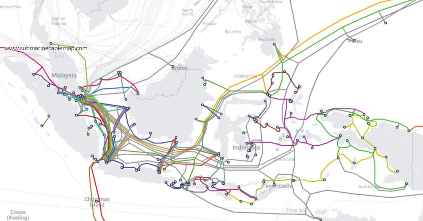
Perhaps no location better represents these trends than Singapore. The city-state has evolved into one of the world’s premier digital hubs, serving as both a landing point and an interconnection center for numerous international systems. Similar growth is occurring throughout Indonesia, where the country’s geography creates continual demand for new domestic and international submarine infrastructure.
Unlike more mature regions, AustralAsia still offers substantial opportunities for entirely new cable systems. However, future investment will increasingly focus on expanding capacity, improving resilience, and extending connectivity beyond traditional metropolitan centers to island nations and emerging markets.
The region also presents unique engineering challenges. Earthquakes, volcanic activity, tsunamis, and tropical storms require careful route selection and robust system design. Environmental protection, particularly around coral reef ecosystems, has become an increasingly important component of project planning.
Despite these complexities, AustralAsia remains exceptionally well positioned for continued expansion. Strong economic growth, continued hyperscale investment, and increasing international bandwidth demand suggest that the region will remain among the industry’s most active markets throughout the remainder of the decade.
EMEA: The Crossroads of Global Connectivity
No region better illustrates the global nature of the submarine cable industry than Europe, the Middle East, and Africa. EMEA serves simultaneously as a destination, a transit corridor, and a bridge connecting three continents, making it arguably the most strategically important submarine cable market in the world.
Europe continues to function as one of the industry’s principal connectivity hubs, supporting dense interconnection among data centers, cloud providers, and international carriers. However, much of the region’s recent growth has occurred beyond Europe itself.
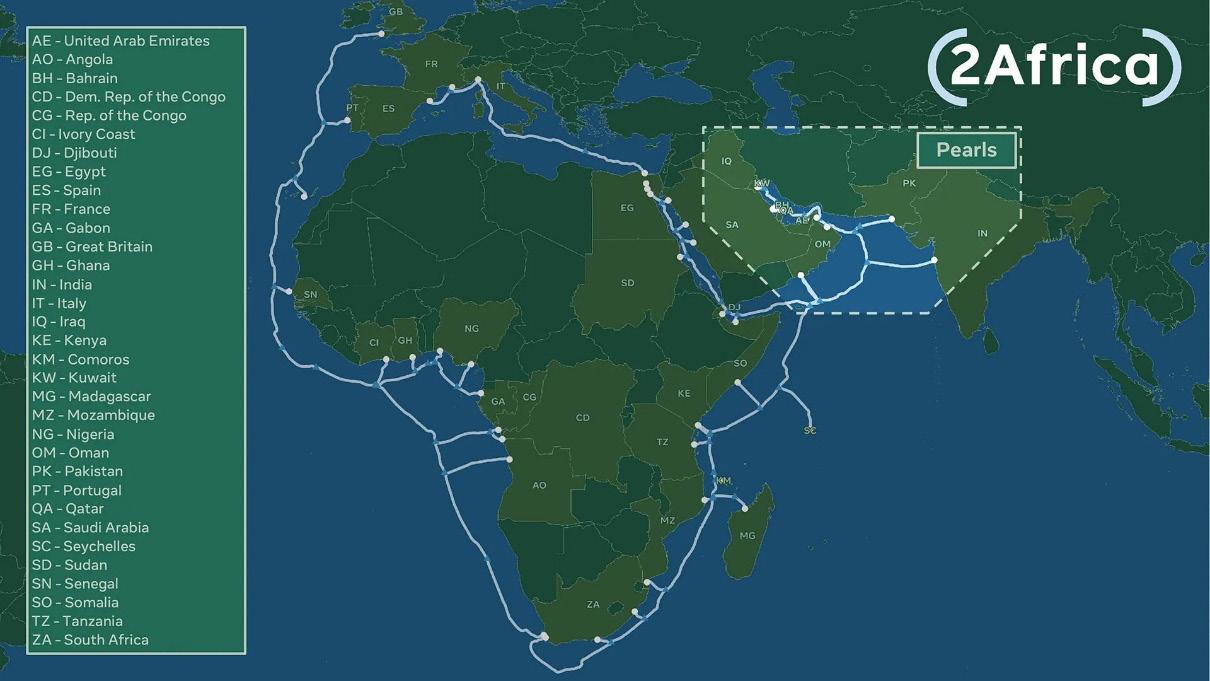
Africa has emerged as one of the submarine industry’s most promising markets. Largescale systems encircling the continent and extending along both east and west coasts are transforming digital access for millions of people while creating new opportunities for cloud providers, telecommunications operators, governments, and investors. Countries that only recently relied on a single international connection are increasingly benefiting from multiple independent routes, improving both resilience and competition.
The Middle East occupies an equally important position. Situated between Europe and Asia, it hosts some of the world’s most critical cable corridors. Routes through the Mediterranean, Red Sea, Arabian Gulf, and surrounding waters carry enormous volumes of global internet traffic every day. Maintaining resilience across these strategically important pathways has become a priority for operators worldwide.
EMEA’s diversity is both its greatest strength and its greatest challenge. Projects frequently involve multiple jurisdictions, regulatory regimes, environmental requirements, and commercial partners. Political instability in some markets, permitting complexity, financing challenges, and security concerns can all influence project schedules.
Nevertheless, long-term prospects remain exceptionally strong. Continued investment throughout Africa, growing cloud infrastructure, expanding regional data center markets, and increasing demand for route diversity ensure that EMEA will remain central to the future development of global submarine communications.
Indian Ocean: The Strategic Bridge Between East and West
The Indian Ocean has quietly become one of the world’s most important submarine cable corridors. While it contains fewer systems than EMEA or AustralAsia, its strategic significance is unmatched. Nearly every major route linking Europe, the Middle East, South Asia, and AustralAsia traverses these waters, making the region a vital bridge for global communications.
Unlike mature regional markets, growth in the Indian Ocean is driven less by local demand than by its role in connecting the world’s fastest-growing digital economies. India continues to emerge as a major global data center market, while increasing cloud investment throughout the Gulf States and Southeast Asia is creating new demand for diverse international routes.
Another defining characteristic of the region is its importance for network resilience. Operators increasingly seek alternatives to traditional choke-
points and single-route dependencies, encouraging new systems that provide additional path diversity between Europe and Asia. Rather than simply increasing capacity, many projects are designed to improve redundancy and reduce operational risk.
The region does, however, present significant challenges. Political instability in several coastal nations, complex permitting processes, varying regulatory environments, and the logistical realities of operating across vast ocean distances can all influence project schedules. Cyclones and seasonal weather patterns also require careful planning during installation and maintenance.
Despite these obstacles, the long-term outlook remains exceptionally positive. As India continues its digital transformation and international cloud providers expand their regional presence, the Indian Ocean will remain one of the industry’s most strategically valuable corridors. Future investment is expected to focus on increasing route diversity while strengthening one of the world’s busiest intercontinental communication pathways.
Polar: The Industry’s Next Frontier
No region better illustrates the balance between opportunity and challenge than the Polar seas.
For decades, engineers have recognized that Arctic routes could dramatically shorten communications between Europe, Asia, and North America. Reduced distance translates directly into lower latency—an increasingly valuable commodity for cloud services, financial trading, artificial intelligence, and other data-intensive applications.
Although only a handful of operational systems currently exist, industry interest continues to grow. Advances in cable technology, specialized installation techniques, and changing Arctic conditions have demonstrated that these routes are technically feasible, even if they remain commercially challenging.
The barriers, however, remain substantial. Construction windows are extremely limited, specialized vessels are required, operating costs are among the highest in the industry, and geopolitical consid-
erations continue to complicate project planning. Environmental stewardship is equally important, requiring developers to balance infrastructure expansion with the protection of some of the world’s most sensitive marine ecosystems.
For now, the Polar region remains a market defined more by potential than by scale. Yet as demand for lower-latency global connectivity continues to grow—and as operators seek alternatives to increasingly congested traditional routes—the Arctic is likely to remain an area of sustained strategic interest. The first developers to overcome its technical and political challenges could fundamentally reshape global network architecture.
Transatlantic: Optimizing the World’s Busiest Digital Highway
Few submarine cable corridors have shaped the Internet more than the North Atlantic.
For decades, the Transatlantic has carried enormous volumes of traffic between two of the world’s largest digital economies. Today, the corridor is less focused on expansion than on optimization. Most major landing locations are already well established, and investment increasingly targets higher-capacity systems, improved resilience, and additional geographic diversity.
Hyperscale cloud providers have fundamentally transformed this market. Modern private cable systems now complement traditional carrier-owned infrastructure, supporting rapidly growing demand from artificial intelligence, cloud computing, streaming media, and enterprise services. Meanwhile, upgrades to existing systems continue extending their operational life while dramatically increasing available bandwidth.
Route diversity has also become a strategic priority. Additional landing stations throughout Ireland, France, Spain, Portugal, and North America reduce dependence on traditional gateways while improving resilience against natural disasters, infrastructure failures, and geopolitical disruption.
The Transatlantic is no longer a story of building the
most cables—it is a story of building the smartest network. Capacity, reliability, operational flexibility, and resilience now drive investment decisions, ensuring that this corridor remains one of the world’s most sophisticated examples of submarine communications infrastructure.
Transpacific: Meeting Explosive Demand Across the World’s Largest Ocean
If the Transatlantic represents stability, the Transpacific represents acceleration.
Rapid economic growth throughout Asia, expanding cloud infrastructure, artificial intelligence, and the continued rise of digital services have made the Pacific one of the fastest-growing international cable markets. New systems are entering service at a pace not seen for many years, driven largely by private investment from hyperscale cloud providers alongside traditional telecommunications operators.
The geography of the Pacific presents unique challenges. Routes span thousands of kilometers between widely separated landing points, while earthquakes, volcanic activity, and typhoons require careful engineering throughout the system lifecycle. Political considerations have also become increasingly important, influencing route selection, landing approvals, and long-term investment decisions.
At the same time, operators are diversifying traditional pathways by incorporating new landing sites across Asia and North America, improving resilience while supporting rapidly expanding regional data center markets.
Looking ahead, the Transpacific is expected to remain one of the industry’s most dynamic corridors. Continued investment in cloud infrastructure, artificial intelligence, and digital content will sustain demand for additional capacity well into the next decade, ensuring that the Pacific remains central to global connectivity.
REACH into the future
Hexatronic is a reliable partner specializing in submarine fiber optic cables ranging from just a few kilometers up to thousands. We focus on providing customized logistics solutions according to the specific requirements for each project and help you every step of the way.
Time and cost efficient solutions
Hexatronic offers complete submarine cable solutions and passive fiber infrastructure based on scalable and future proof technology.
• Flexible approach for each and every project
• High fiber count cables
• Fast response, turnaround and delivery times
• No project is too big or small
• Swedish quality and technical proficiency
• Easy to do business with!
EXPLORING ALIGNMENT OF RESILIENCE AND SUSTAINABILITY IN SUBSEA TELECOMS NETWORKS
by Derek Cassidy, Nick Morris & Andrew Parsons
Subsea cables are often described as the hidden infrastructure of the digital economy.
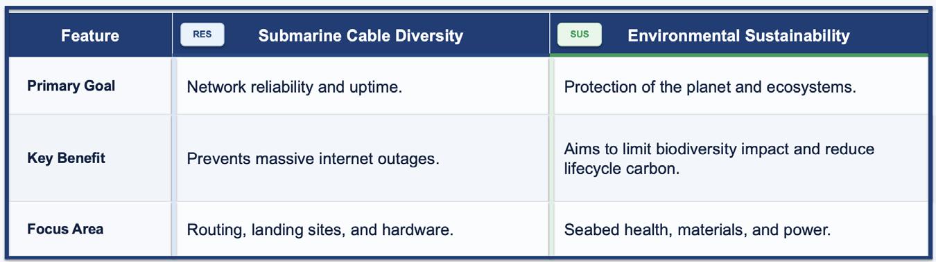
The global digital economy rests upon a surprisingly physical foundation: a vast, intricate network of fibre-optic cables criss-crossing the ocean floor [1]. These subsea cables are the foundational infrastructure of the modern digital economy, carrying an estimated 99% of intercontinental data traffic[2] and facilitating everything from high-frequency financial trading to essential cloud services. However, as global dependence on this infrastructure grows, so too does the complexity of the challenges it faces. The dual imperatives of resilience (the ability to withstand and recover from physical or cyber disruptions) and environmental sustainability have emerged as the defining pillars of future subsea development [3].
Historically, the subsea cable industry focused primarily on connectivity and capacity. Yet, an escalating landscape of threats, ranging from climate-induced geological shifts and accidental maritime interference to intentional sabotage, has underscored the vulnerability of these increasingly critical systems [4]. Simultaneously, the industry is under increasing pressure to align with global “Blue Economy” goals. While subsea cables are often cited as a lower-carbon alternative to satellite transmission, their lifecycle (from manufacturing and specialised vessel deployment to decommissioning) presents a distinct environmental footprint that must be managed within sensitive marine ecosystems [5]. These pressures also connect to the wider critical-national-infrastructure and security agenda, a link this paper notes without developing into a policy prescription.
For years, resilience and sustainability were treated as parallel conversations. Resilience lived with engineers and operators; sustainability sat somewhere between corporate reporting and regulatory engagement. That separation is breaking down. Why? Because unplanned intervention is a double penalty. A fault that forces an urgent repair doesn’t
just risk downtime. It also triggers some of the most resource-intensive activity in the ecosystem: vessel mobilisation, port calls, specialised crews, spares movement, onshore works, and the operational overhead of restoring service under pressure [6]. When repairs are slow—because vessels are scarce, weather windows are tight or permits take time—the system runs “hotter” for longer, often leaning on less efficient operating modes and backup power [7].
At the same time, sustainability constraints are becoming operational constraints. Power availability and quality, local water stress, flood risk, and permitting friction increasingly shape where landing infrastructure can be built and how it can be operated. In other words, sustainability is not just a reporting line item; it can become a real-world limiter of resilience. Increasingly these constraints are also codified in regulation, for example the EU Corporate Sustainability Reporting Directive (CSRD) on disclosure, and the EU Critical Entities Resilience Directive and NIS2 on critical-entity resilience and cyber risk [8]. That observation is accurate, but incomplete. What matters in practice is the whole subsea ecosystem: the cable itself, the landing and interconnection environment, the data centres and backhaul that carry the traffic, and the operational machinery—ships, spares, ports, permits, and people—that keeps everything running when something goes wrong [9].
And things do go wrong. Most faults are accidental, not mysterious: anchors, fishing activity, shoreline dynamics, seabed movement, and plain bad luck [10]. The resilience question is familiar: how can operators keep service running when a fault occurs? Increasingly, there is a second question that cannot be separated from the first: how can that be done without turning every incident into a high-carbon, high-impact emergency response [11]?
This paper explores the intersection of these two critical domains. It examines how innovative engineering and diversified routing can bolster cable resilience against a backdrop of increasing geopolitical and environmental volatility. Furthermore, it
analyses the industry’s transition toward sustainable practices, assessing how the drive for “greener” infrastructure can coexist with the rigorous technical demands of deep-sea operations [12]. By synthesising current technological trends with environmental policy frameworks, this discussion argues that the long-term viability of global connectivity depends on a holistic approach that treats security and ecology not as competing interests, but as integrated requirements.
The next generation of subsea infrastructure is increasingly likely to be evaluated on both. The remainder of this paper sets out a working definition of network diversity [13,14] and environmental sustainability in a subsea context, then explores the operational, design, and lifecycle choices that influence both. It is intended for a senior subsea, telecoms, infrastructure, and policy audience and is offered as a framework for evaluating dual-benefit decisions rather than as a prescriptive standard.
Network diversity [15] encompasses all aspects of submarine cable infrastructure and the networks behind them. Diversity is a primary means of achieving resilience: physically diverse routes, landings, suppliers and backhaul reduce the chance that a single event removes service. Three illustrative areas are:
• Geographic Diversity: Ensuring cables are laid in different physical paths. If an earthquake or an anchor drag happens in one specific area, cables on a diverse route are less likely to be affected by the same localised event, though major seismic or seabed events can affect physically separated routes together.
• Landing Station Diversity: Terminating cables at different physical buildings or coastal locations. If one landing station loses power or suffers a fire, the other can carry the traffic, subject to the surviving station having sufficient installed capacity, power, and terrestrial backhaul.
• Supplier/System Diversity: Using different manufacturers and technologies (like different fibre types or repeaters) to avoid a “single point
of failure” if a specific brand of hardware has a systematic defect. In practice, supplier diversity is constrained by a concentrated wet-plant supply market [16].
These three dimensions are illustrative rather than exhaustive. In practice, network diversity also extends to terrestrial backhaul, power supply, repair readiness, permitting, and concentration of shared risk across landings and corridors.
Environmental sustainability spans a similarly broad set of considerations. Four illustrative areas relevant to submarine cable infrastructure are:
• Marine Protection: Conducting thorough surveys to avoid sensitive habitats like coral reefs, seagrass beds, or marine protected areas (MPAs). In many jurisdictions this is a legal requirement, for example Appropriate Assessment under the EU Habitats and Birds Directives, OSPAR, and national marine licensing, not only good practice [17]
• Low-Impact Installation: Using specialised “ploughs” to bury cables deep enough to be safe from fishing gear but with minimal disruption to the seabed.
• Material Efficiency: Selecting materials with low toxicity and minimal leaching potential, assessed against applicable standards, across the design life (commonly around 25 years) [18].
• Energy Efficiency: Optimising the power feeding equipment (PFE) at landing stations to use less electricity and, where possible, sourcing that energy from renewables.
As with diversity, these four areas are illustrative. A wider view of sustainability also includes operation-
SUSTAINABLE SUBSEA
al and repair activity over the full asset life, utility robustness at landing sites, and end-of-life treatment, all of which can carry material lifecycle impacts.
The physical scope that will be addressed in this paper runs from the connection of the terrestrial network to the subsea optical transmission equipment housed within the CLS or directly within a data centre, through to the subsea cable network and its components to terrestrial networks on the other side of the network [19].
associated with local fish populations, though current evidence does not establish this. These effects are debated, vary by location, and are not universally accepted, so they are best treated as context-dependent rather than as general benefits [22].
TOWARDS A GREENER SUBSEA FUTURE
Additionally, deployment, operational and decommissioning phases will be considered with respect to both resilience and sustainability.
In practice, the two dimensions above are operationally linked rather than fully separable, and many design choices deliver against both at once. Whether decommissioning requires recovery of buried cable is becoming a more active question. In international waters, buried cables are, in current practice, commonly left in place, subject to evolving frameworks under UNCLOS. Where coastal-state or rights-holder regimes are beginning to introduce decommissioning or recovery provisions, the financial incentive can shift toward removal, though the cost of recovery may only pay back over a multity year horizon. Cable weight is also a relevant factor: armoured shallow-water cables can be up to circa 8 tonnes per km, against around 1 tonne per km for unarmoured deep-sea cable. A first-pass impact estimate suggests that recovery of armoured shallow-water cable may carry a lower per-km lifecycle impact than recovery of deep-sea cable, though this comparison requires lifecycle data not yet publicly available [20].
Industry note: While laying a massive cable sounds disruptive, submarine cables are often characterised as comparatively low impact compared to other offshore industries [21] Once buried, they may, in some settings, provide reef-like habitat, and the restricted fishing zones around them sometimes been
The future of the subsea ecosystem increasingly depends on disciplined use of materials, energy, and other resources across the full asset life. Integrating sustainability considerations into the lifecycle of submarine cable infrastructure can support the long-term viability of the industry and reduce its environmental footprint over time
Futureproofing this critical infrastructure requires a holistic approach where new cables, landing stations, and data centres minimise the strain on existing power, water, and wastewater resources.
To support this evolution, the following design considerations are worth consideration for prioritising:
• Resilient Cable Design: Prioritise enhanced fibre protection to reduce outages, thereby minimising the high carbon footprint generated by cable repair vessel deployments. The scale of this saving is a priority for further work, for example comparing vessel fuel burn per repair voyage against installation-phase embodied carbon.
• Strategic Routing Diversification: Where practical, reduce reliance on highly congested landing corridors (the Sydney landing area is one frequently discussed example) [23] in favour of greater spatial separation, improving physical security and system longevity.
• Integrated Environmental Sensing: Incorpo-
rate advanced sensing capabilities into cable operations to provide real-time monitoring and proactive incident mitigation.
• Standardised Integrity Monitoring: Where supported by the system architecture, adopt continuous structural and electrical integrity monitoring to detect shunt faults and integrity issues early.
• Infrastructure Consolidation: Where operationally and commercially feasible, consider integrating Cable Landing Station (CLS) functions with existing neutral Data Centres (DC) to reduce duplicated construction and limit additional draw on local utilities, balanced against shared-risk and physical-separation considerations.
FIVE MOVES THAT DELIVER BOTH A GREENER FOOTPRINT AND A TOUGHER NETWORK
1. Design to avoid repairs, not just survive them. The cleanest repair is the one that is never required. That means investing in the parts of the system that historically drive the most avoidable faults: shore-end protection, burial strategy matched to local seabed conditions, robust transition engineering, and route planning that accounts for highrisk human activity and seabed dynamics.
This is not only about uptime. Each avoided fault is an avoided mobilisation event, which is where a lot of the ecosystem’s real-world footprint shows up.
2. Break the “congestion corridor” mindset. In many markets, the default pattern has been to land where everyone else lands—because that is where facilities, interconnection, and permitting precedent already exist. Over time, this creates crowded
shore approaches and common-mode risks.
Greater spatial separation of landings, and smarter use of regional diversity, improves physical security and reduces correlated failures. It also gives operators more options when local constraints tighten—whether those constraints are political, environmental, or utility-related.
3. Treat integrity monitoring as a design target for new builds, where the architecture supports it. If a system cannot be observed clearly, it cannot be managed efficiently. Monitoring is not just a resilience tool; it is a sustainability lever because it reduces uncertainty, shortens investigations, and enables earlier intervention before issues cascade.
Environmental sensing, condition monitoring, and operational telemetry should be designed into systems as standard capabilities—not as “nice-to-have” add-ons negotiated late in a project.
A modern subsea ecosystem needs continuous insight into structural and electrical integrity, which is distinct from the environmental and operational sensing described above, so that emerging issues can be detected early and handled deliberately. The goal is simple: move from “discover the problem during the outage” to “see it forming and plan the response.”
This is one of the highest-leverage ways to reduce both downtime and the churn of unnecessary mobilisation.
4. Reduce or cease unnecessary duplication of infrastructure . In many cases, the most sustainable build is the one that reuses what already exists. This can also mean reusing the routes, ducts and shore-end horizontal directional drilling (HDD) of retired cables, where their condition and permitting allow. Where it is operationally and commercially feasible, in-
tegrating landing functions into neutral data centre environments can reduce duplicated construction, shrink the footprint of utility consumption, and improve physical security and operational staffing efficiency [19,24].
This does not mean collapsing everything into a single shared-risk box. It means being deliberate about which functions must be physically separate, and which can be consolidated without creating new single points of failure. Collocation also depends on practical constraints, including distance from the beach manhole, high-voltage power feed in an IT environment, optical reach, and security separation, and its benefits should be supported by independent evidence rather than asserted.
5. Optical switching as an emerging tool in the repair equation. An emerging shift in subsea design is what modern optical switching and reconfigurable branching architectures may make possible, where the wet-plant architecture is designed to support it. In much of the deployed fleet today, branching units are passive and fixed, so this is best read as a forward-looking capability rather than current general practice [25].
With survivable re-routing through diverse wet-plant branches and landing paths, some failures no longer have to trigger an immediate, high-pressure repair response. Traffic can be managed in a degraded-but-working mode while operators plan a controlled intervention window.
That matters because it changes the character of repair:
• From emergency mobilisation to scheduled maintenance
• From repeated “rush” deployments to more efficient work packaging
• From maximum operational disruption to de-
liberate coordination across vessels, ports, spares, and permits
This is not a complete solution. Physical diversity, terrestrial separation, and sound operational practices remain necessary. But it is a genuine opportunity to reduce “peak impact” events while improving survivability. The benefit depends on system topology, terrestrial diversity, operational maturity, and cost, and is not equally available in every architecture. Optical switching is therefore best treated as one emerging tool that may reduce emergency repair urgency in certain configurations rather than a universal answer.
WHAT “GOOD” LOOKS LIKE: A PRACTICAL RESILIENCE-AND-SUSTAINABILITY SCORECARD
To move this discussion from principles to decisions, the industry needs a small set of signals that can be used consistently across projects. Operators, project sponsors, lenders, and regulators can use these signals during design review, project assurance, and post-incident learning to test where dual benefits are realistic and where trade-offs remain. For example:
• Diversity that is real (not just on paper): physically separated routes, landings, and terrestrial backhaul
• Survivability under defined scenarios: clear survivability intent under defined fault scenarios, for example loss of one or two cables or landings (sometimes termed N-1 / N-2), with tested restoration plans
• Repair readiness: vessels, spares, ports, and permits aligned to realistic fault scenarios
• Utility robustness: power architecture and backup strategy designed for grid stress and extreme events
• Operational maturity: monitoring-to-action time, change discipline, incident recurrence rates
• Lifecycle efficiency: design choices that reduce intervention frequency and shorten restoration windows
This does not require perfection. It requires transparency: projects should be able to explain where they are strong, where they are exposed, and which mitigation provides the biggest dual benefit.
THE TAKEAWAY: BUILD SYSTEMS THAT FAIL LESS, RECOVER FASTER, AND CONSUME LESS
The subsea ecosystem is expanding globally, and the risk landscape is not getting simpler. Resilience cannot be solved only with more fibre pairs, and sustainability cannot be solved only with reporting.
The projects that tend to perform best on both dimensions are those that:
• avoid faults where possible
• limit impact when faults occur
• restore service fast and predictably
• and do all of it with fewer high-carbon, high-disruption interventions
This could be a practical meeting point of resilience and sustainability: not a trade-off to manage after the fact, but a design and operating philosophy built in from day one. Some trade-offs remain unresolved and will require better operational data, more transparent reporting, and shared industry learning to close out. This paper aims to inform that work rather than to conclude it.
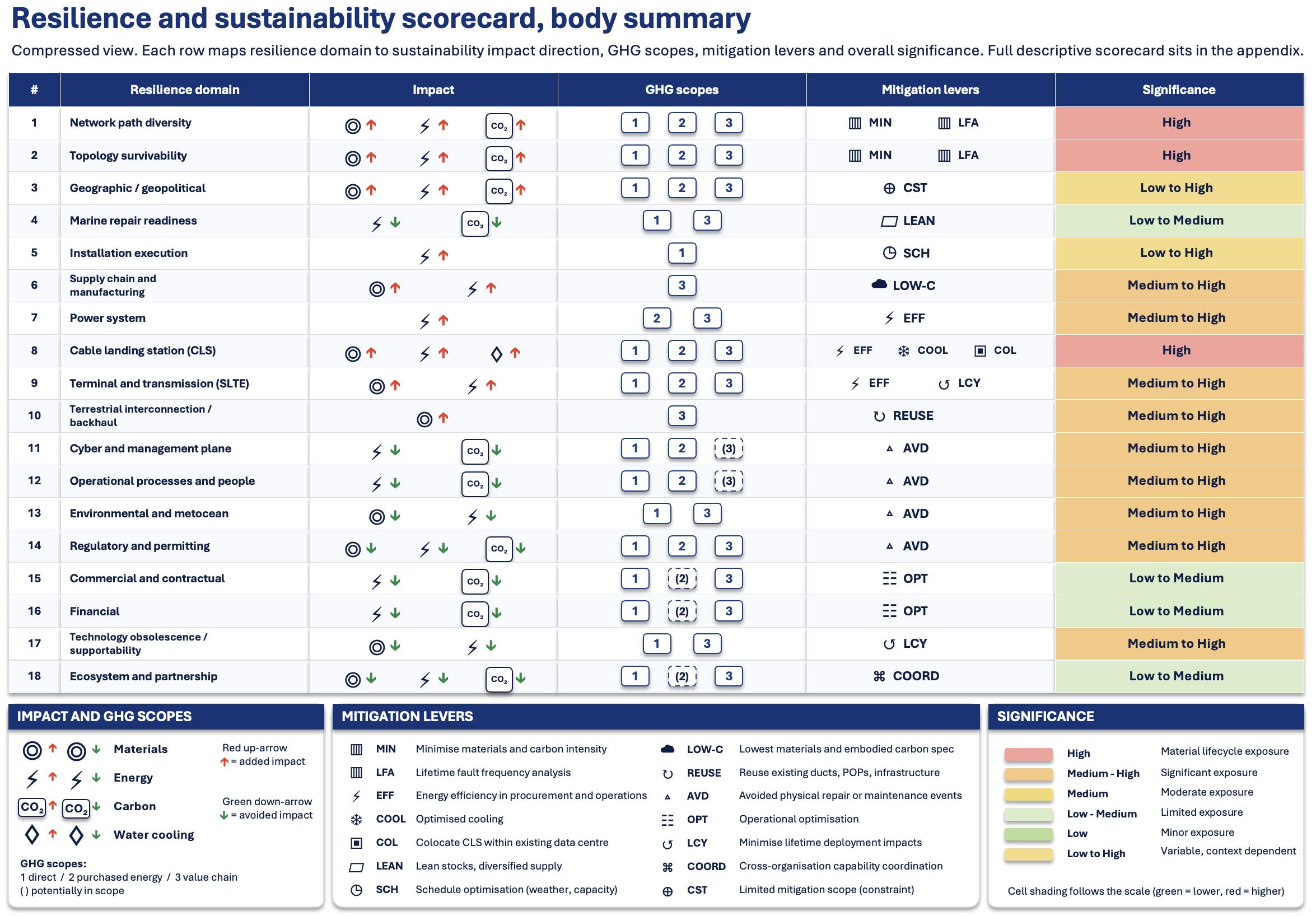
The same fault-avoidance logic carries into procurement and lifecycle assessment: lower-impact, more resilient options can be scored and selected rather than asserted. The eighteen resilience areas identified in Table 1, above may be categorised within the framework used for generating Environmental Product Declarations (EPDs) [26] based on a life cycle assessment conducted in accordance with ISO 14044 and structured under the relevant Product Category Rules. No widely adopted Product Category Rule specific to subsea cable systems current-
ly exists, so system-level comparability is limited and EPDs apply mainly at component level.
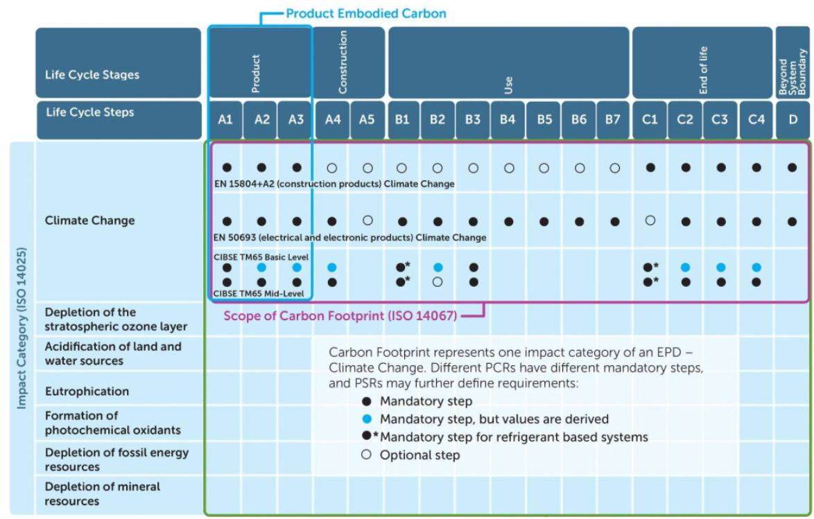
EPDs may be generated for specific materials and products and quantify environmental impact in terms of attributes which include: Climate Change/ Global Warming Potential (GWP, relative to KgCO2e), Ozone Depletion, Acidification, Eutrophication Potential (EP) in marine, freshwater and terrestrial environments, photochemical oxidants, abiotic depletion (applied to minerals and fossil fuels), total energy required in the process (J), Water Deprivation Potential (WPD). Note that GHG Protocol Scope
1, 2 and 3 (organisational emissions categories) are distinct from these EPD life-cycle modules [27]; the appendix table uses both, so a short key clarifying the two would help the reader.
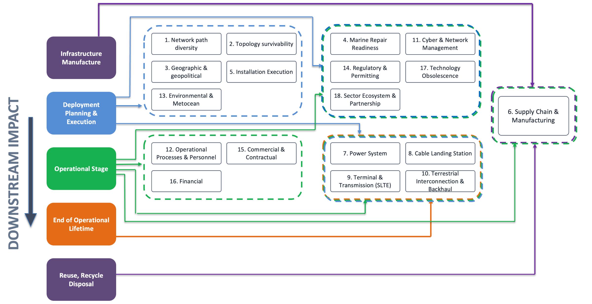
The stages described in Figure 1, below correspond to the following stages in an EPD:
• Infrastructure Manufacture: Product Stage (A1A3) comprising raw materials sourcing, transport and manufacturing.
• Deployment Planning and Execution: Installation/Construction (A4, A5), consisting of trans-
Figure 1, above: represents typical life cycle stages and steps as may be applied to different product and material categories, such as construction products and electrical and electronic products.
port and installation of component materials and infrastructure.
• Operational Stage: Use Stage (B1-B7): comprising use, maintenance, repair, replacement, refurbishment, energy and water use, each with the associated impacts categories detailed above.
• End of Operational Lifetime: End of Life Stage (C1-C4), consisting of disassembly, transport of disassembled parts, processing, disposal if appropriate.
• Reuse, Recycle, Disposal: Reuse Recovery Recycling Potential (D), essentially quantification of the proportion of the components which may be reused/repurposed, recycled and recovery of materials.
Note that the total project impacts of initial stages of infrastructure manufacture and deployment and
planning represent constraints on downstream overall sustainability, energy efficiency and also resilience performance. For example, decisions on the selection of power system equipment impact operational stage energy efficiency and resilience measures such as mean time to failure, availability of component replacement, planned preventative maintenance requirements and upgrade pathways. Therefore, the development and application of a procurement policy which includes scoring for sustainability and resilience attributes for both infrastructure and services can be useful if not critical tool in the process of designing and planning a subsea project.
In particular, the implementation of a Pre-Qualification Questionnaire (PQQ) in combination with questions in the tender which enable scoring of the tender in terms of sustainability and resilience attributes
Figure 2: Visualisation of the categorisation of the identified resilience areas in Table 1 across a product or project lifecycle.
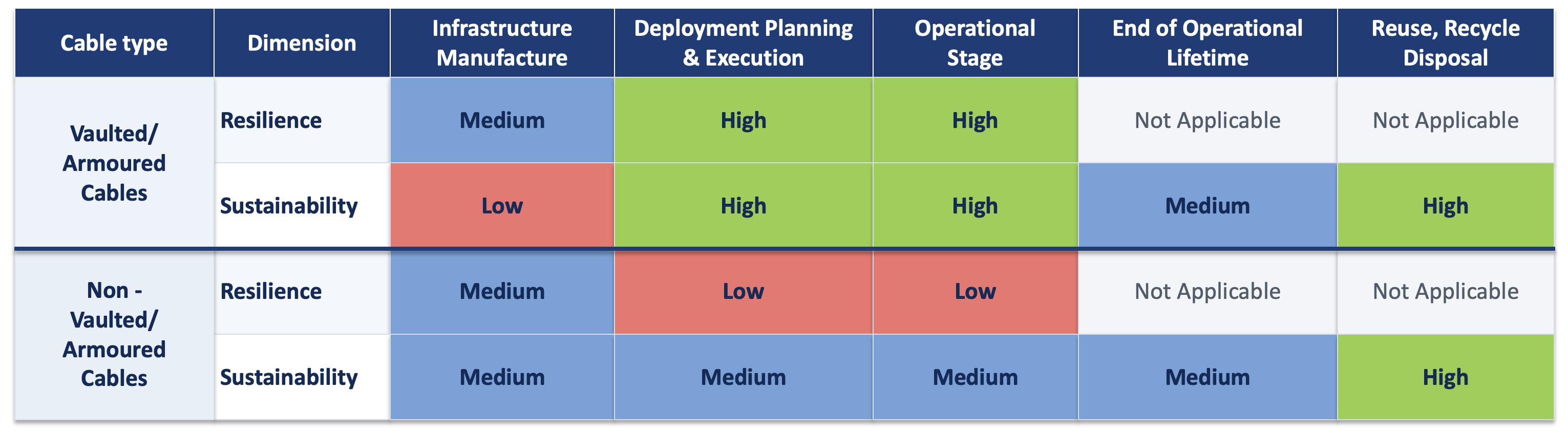
Figure 3, representation of a total lifecycle environmental and resilience matrix for comparing vaulted/armoured and non-vaulted/armoured cables.
which can assist to acquire materials and infrastructure which provide materially stronger sustainability and resilience performance. For example, suppliers that are able to provide EPDs are favoured over those which are not and the sustainability impacts in areas such as embodied carbon, abiotic materials and energy usage in manufacture, and additionally for powered equipment and infrastructure, energy efficiency provides indications of relative performance. Likewise, appropriate attributes at each of the stages indicated in Figure 2 may be compared, such as maintenance requirements.
The framework represented in Figure 2, above, may be used in order to quantify environmental and resilience impacts of different options at the infrastructure, system or sub-system level and therefore
score and compare alternatives.
Figure 3, below, is a representative total lifecycle environmental and resilience matrix for comparing vaulted/armoured and non-vaulted/armoured cables using this approach. Whereas vaulted/armoured cables contain more materials and have higher impacts in attributes such as carbon emissions than the alternative, they are more resilient in deployment and operations, hence the overall environmental impact may be less than the alternative. Note that specific attributes or combinations of attributes may be used to quantify the impacts at each of the stages, resulting in low to high scores as shown in Figure 3.
The same approach may be applied at a multi-com-
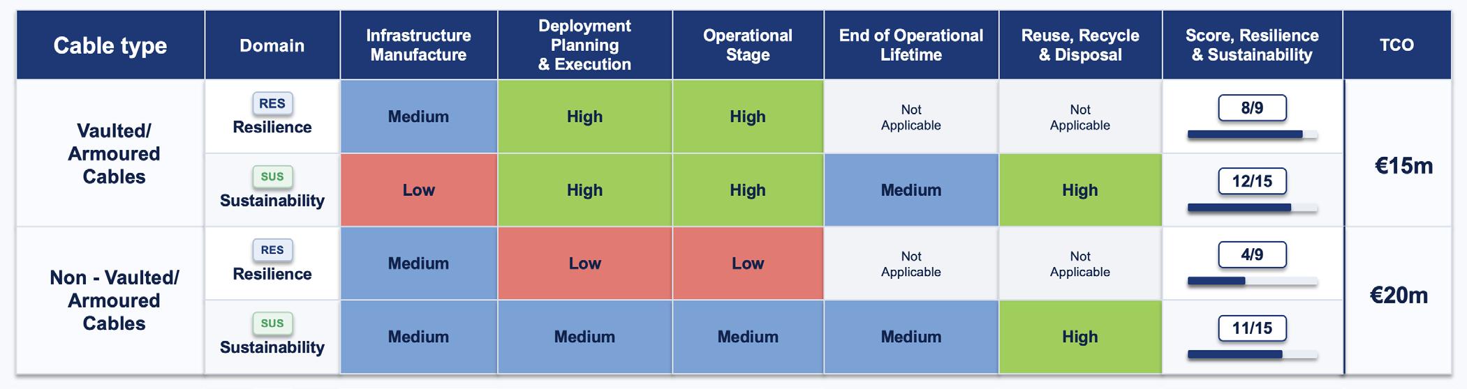
Figure 4, representation of a total lifecycle environmental and resilience matrix for comparing vaulted/ armoured and non-vaulted/armoured cables. In order to illustrate the quantitative comparison, 3, 2 and 1 have been assigned to High, Medium and Low scores for resilience and sustainability. As an indicative illustration only, total cost of ownership might be of the order of EUR 50k per km for a vaulted or armoured option against EUR 35k per km for a non-vaulted option, covering purchase, deployment, maintenance, repair and replacement.
ponent or system and sub-system level, thereby enabling comparison of multiple combinations. Clearly, for the resilience component a probability versus impact risk matrix is applied to the alternatives.
In addition to the approach detailed above, alternative methods of attaining the same goal may also be compared. For example, in certain locations it may be feasible to collocate the functions of the Cable Landing Station (CLS) within a data centre [29]. In suitable locations this option may provide an environment and power supply already optimised for energy efficiency and resilience , and may therefore represent a lower environmental impact and higher resilience approach, subject to distance, power-feed, optical-reach and security-separation constraints and to independent evidence.
Furthermore, in the CLS example above the Total Cost of Ownership (TCO: CAPEX plus OPEX plus decommission) may also be lower for the collocated CLS, mainly through shared power, cooling and site costs and avoided duplicate construction; this is a qualitative comparison and per-km figures are not yet established. An additional dimension to the approach represented by Figure 3 could be to add TCO to aid the comparison of alternatives, as illustrated in Figure 4, below [1]
Clearly, the scoring above is for illustrative purposes, the approach must be applied on a project by project basis. In an actual example: for sustainability selected attributes with quantitative values, such as carbon emissions, or a combination of attributes, may be assigned and compared; whereas for resilience the scores resulting from probability versus impact risk matrix or another methodology may be applied.
The combination of alternatives for all systems that constitute a project includes the highest and lowest resilience and sustainability possibilities. By consistently applying frameworks which quantify the resilience and sustainability of different project systems and sub-systems it is feasible to identify the optimal combination which fulfils resilience requirements for the minimum sustainability impact. Further, this
approach enables the identification of cases of high resilience and high sustainability which may not be immediately apparent, as illustrated in Figure 4.
REFERENCES
[1] Chesnoy, J., “Undersea Fibre Communication Systems, Science Direct, 2016.
[2] Telegeography, “Do Submarine Cables Account For Over 99% of Intercontinental Data Traffic?”, 4 May 2023, https://resources.telegeography. com/2023-mythbusting-part-3. Accessed 17-062026.
[3] Clare, M., “Submarine Cable Protection and the environment”, International Cable Protection Committee, 2023.
[4] Subsea cables: how vulnerable are they and can we protect them?”, Joint Research Centre, European Union, 2025.
[5] “PFOW Enabling Actions Project: Subsea Cable Lifecycle Study”, European Marine Energy Centre, Crown Estate, 2015.
[6] Graz, A., Camellini, M., Hine, E., Novelli, C., Roberts, H., Floridi, L., “Submarine Cables and the Risks to Digital Sovereignty”, SSRN Electronic Journal, 2024.
[7] Starosielski, N., “The undersea network”, Duke University Press, 2015.
[8] EU instruments: Corporate Sustainability Reporting Directive, Directive (EU) 2022/2464, https://eur-lex.europa.eu/eli/dir/2022/2464/ oj; Critical Entities Resilience Directive, Directive (EU) 2022/2557, https://eur-lex.europa.eu/ eli/dir/2022/2557/oj; and the NIS2 Directive (EU) 2022/2555, https://eur-lex.europa.eu/eli/ dir/2022/2555/oj. Applicability to a given subsea operator depends on national transposition and entity designation. Accessed 17-06-2026.
[9] International Cable Protection Committee (ICPC), “Media Enquiries and Frequently Asked Questions”, updated 20 May 2026, https://www.iscpc. org/news/media-enquiries/. ICPC reports about
ASK THE EXPERT
Question for the author(s)? Click here!
150 to 200 cable faults per year, of which roughly 70 to 80 per cent are caused by accidental human activity, principally commercial fishing and ships’ anchors. Accessed 18-06-2026.
[10] Wilkinson, H., D., “Submarine Cable Laying and Repairing”, The Electricians Printing and Publishing Co. Ltd., 1910.
[11] “Third Party Damage to Underground and Submarine Cables”, Cigre, Working Group B1.21, 2009.
[12] Crain, J., K., “Assessing Resilience in the Global Undersea Cable Infrastructure”, Naval Postgraduate School, California, 2012.
[13] Starosielski, N., ET AL, “Report on best practices in subsea telecommunications sustainability”, Sustainable Subsea Networks Report, Suboptic Foundation, 2023.
[14] Morris, N., Booth, J., “Report on best practices in cable station landing station sustainability”, Sustainable Subsea Networks Report, Suboptic Foundation, 2025.
[15] Viewpoints, Industry. Redundancy, Diversity and Route Strategy: What Enterprises and Carriers Actually need/Telecom Ramblings, 2026. https:// www.telecomramblimgs.com/2026/04/ redundancy-diversity-and-route-strategy-what-enterprises-and-carriers-actually-need/. Accessed 18-06-2026.
[16] On supply concentration see Carnegie Endowment for International Peace, “Securing Europe’s Subsea Data Cables”, 2024. https:// carnegieendowment.org/research/2024/12/securing-europes-subsea-data-cables. Accessed 18-06-2026.
[17] See OSPAR Commission, “Assessment of the environmental impacts of cables” (2009) and the OSPAR Guidelines on Best Environmental Practice in cable laying and operation; and, on the Natura 2000 framework, the EU Habitats Directive (92/43/EEC) and Birds Directive (2009/147/EC), European Commission. https://
[18] Telegeography, “Is the Lifespan of a Submarine Cable Really 25 Years?”, 2023, https://resources. telegeography.com/2023-mythbusting-part-2. 25 years is a common minimum design life; cables are often retired earlier for economic obsolescence and occasionally operated longer. Accessed 11-06-2026.
[19] Cassidy, D. “From Cable Stations to Data Centres”, Subtel Forum, Vol. 115, 2020.
[20] Clare, M.A., et al., “Environmental considerations for the decommissioning of subsea cables”, Journal of Environmental Management 396 (2025) 127962, https://doi.org/10.1016/j.jenvman.2025.127962:Accessed 21-06-2026.
[21] On the comparatively small footprint of cables relative to other marine and offshore uses, see ICPC and UNEP-WCMC, “Submarine Cables and the Oceans: Connecting the World” (2009), https://www.iscpc.org/documents/?id=132: Accessed 19-06-2026.
[22] Clare et al. (2025), as cited above, find that biological colonisation of cables is the exception rather than the norm and that any reef effect is very localised; the study does not evidence cables increasing local fish populations. Accessed 19-06-2026.
[23] The Northern Sydney area is a recognised example of landing concentration; see the ACMA Sydney submarine cable protection zones, https://www.acma.gov.au/zones-protect-sydney-submarine-cables, and industry reporting on constrained landing points in that corridor. Accessed 12-06-2026.
[24] Cassidy, D., “From local connectivity to global reach: The new age of Communication”, Subtel forum, Vol. 119, 2021.
[25] Reconfigurable optical add-drop and wavelength-selective-switch branching are deployed on some recent systems (for example NTT’s
MIST and the Apricot system, https://www.submarinenetworks.com/en/systems/intra-asia/ apricot) but most of the installed fleet uses passive, fixed branching units, so the capability is emerging rather than general practice.Accessed 21-06-2026.
[26] EPDs are Type III environmental declarations verified in compliance with EN ISO 14025, based on a life cycle assessment to EN ISO 14044. Specific rules apply to types of products, for example EN 50693:2019 for electrical and electronic products and EN 15804:2012+A2:2019 Accessed 19-06-2026.
[27] The GHG Protocol Corporate Standard (WRI and WBCSD), https://ghgprotocol.org/corporate-standard, defines organisational Scopes 1, 2 and 3; these are distinct from the product life-cycle modules A1 to D defined in EN 15804:2012+A2:2019 used for EPDs: Accessed 16-06-2026.
[30]“Marine environmental impact assessment report”, P1975_R4500_RevF, July 2024.
Derek Cassidy is a Chartered Engineer with more than 33 years of experience in telecommunications, specializing in submarine cable systems and optical engineering. He is currently pursuing PhDs in Optical Engineering and Submarine Cable Technology at UCD, serves as Chair of the Irish Communications Research Group, and is Technical Lead for the Valentia Transatlantic Cable Foundation. Derek has authored more
than 50 technical papers, holds multiple engineering patents, and is an active contributor to international standards and industry organizations.
Dr. Nick Morris is a consultant specializing in data centres, sustainability, and digital infrastructure. With more than 16 years of experience in the data centre sector, he advises industry and government on energy efficiency, cloud strategy, AI-driven infrastructure growth, and resilience. He is the lead author of the 2025 Sustainable Subsea Networks report on cable landing station sustainability and has led numerous projects spanning data centres, submarine telecommunications, and renewable energy technologies.
Andrew Parsons is a commercial and strategy executive with more than 25 years of experience in subsea telecommunications and digital infrastructure. A Co-Founder and Chief Commercial & Strategy Officer of IOEMA and founder of SubMatrix, he specializes in subsea cable systems, global optical networks, and large-scale infrastructure projects. Andrew also serves on the Advisory Board of Sustainable Subsea Networks, focusing on sustainability, resilience, and innovation in subsea communications.
A BROADER FLEET, LESS DEFINED
by Kieran Clark
May and June present a cable-ship fleet that is active across a wide geographic field, but less clearly organized around identifiable work.
The global map remains busy from the North Atlantic and Europe through the Indian Ocean, East and Southeast Asia, and across the Pacific. What changes is the character of the pauses within that footprint.
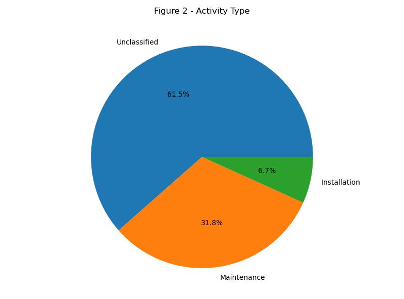
The period contains 6,060 idle points, up from 4,323 in March and April, an increase of 40.2%. Yet that larger total does not translate into a stronger maintenance or installation signal. Unclassified activity expands to 61.5% of all idle points, while maintenance falls to 31.8% and installation to 6.7%.
The result is a broader but less operationally defined fleet picture. Ships continue to occupy the same major cable basins, and depot activity remains comparatively steady. At the same time, fewer pauses align with the activity patterns that made March and April easier to interpret. May-June therefore reads as a period of reach without equivalent clarity.
FLEET ACTIVITY AT A GLOBAL SCALE
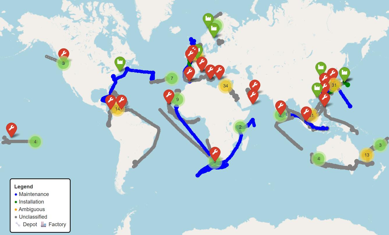
Figure 1 shows activity spanning the familiar geography of the subsea cable network. Dense clusters remain visible around northwestern Europe and the North Atlantic, with additional concentrations in East and Southeast Asia. Long vessel tracks also cross the Indian Ocean, wrap around southern Africa, and extend through the Pacific.
The North Atlantic and European pattern is the most layered. Maintenance-linked tracks run between North America and Western Europe, while facility markers gather around the United Kingdom, France, the Mediterranean, and northern European waters. The region still displays the dense combination of routes and shore-side support that makes it a persistent center of cable-ship operations.
East and Southeast Asia form the other major concentration. Activity is visible around Japan, Korea, the South China Sea, Singapore, and the routes leading into the eastern Indian Ocean. Maintenance, installation, and unclassified points appear close together, creating a mixed regional picture rather than a single dominant operating mode.
Elsewhere, the map emphasizes connection more than concentration. Tracks around southern Africa link Atlantic and Indian Ocean routes, while Pacific activity reaches toward western North America, island corridors, and Australia. Many of these tracks are unclassi-
Figure 1: Vessel Activity Map (May-June 2026)
fied, a visual pattern consistent with the larger unclassified share in Figure 2.
THE ACTIVITY MIX LOSES DEFINITION
Figure 2 captures the period’s central shift. Of 6,060 idle points, 3,726 are unclassified, 1,925 are associated with maintenance, and 409 with installation. Those counts produce shares of 61.5%, 31.8%, and 6.7%, respectively. Unclassified activity is not simply the largest category; it is larger than maintenance and installation combined.
The contrast with March-April is substantial. Maintenance previously accounted for 53.2% of idle activity and installation for 23.5%, while unclassified activity stood at 23.3%. Together, maintenance and installation fall from 76.7% to 38.5% of the mix. Even as total idle activity rises, maintenance points decline by 16.3% and installation points by 59.7%.
2: Activity Type (May-June 2026)
That combination calls for a careful reading. The fleet is not absent from operational regions, and recognizable work remains visible. But the balance has shifted toward pauses that cannot be assigned as confidently to maintenance or installation. The period is busier in count and less definite in composition.
INFRASTRUCTURE CONTEXT
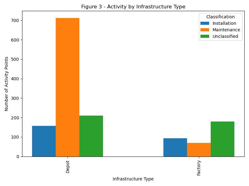
Figure 3 shows that depots remain the clearest operational anchors. Depot-linked activity totals 1,080 idle points: 712 maintenance, 158 installation, and 210 unclassified. Maintenance therefore accounts for 65.9% of the depot total, preserving the familiar association between depots and repair readiness.
The depot profile is also comparatively stable against March-April. The total slips only 2.9%, from 1,112 to 1,080 points. Within that total, maintenance eases from 749 to 712 and installation from 235 to 158, while unclassified activity rises from 128 to 210. The anchor remains, but its internal mix becomes less sharply defined.
Factory-linked activity changes more visibly. The
May-June total is 343 points, including 94 installation, 69 maintenance, and 180 unclassified. Unclassified activity makes up 52.5% of the factory total, while installation accounts for 27.4%. This is a reversal from March-April, when installation led factory-linked activity with 329 of 518 points.
The two facility types therefore tell different stories. Depots still pull the activity mix toward maintenance, even with more unclassified points. Factories no longer show the same strong installation signature. The pattern does not rule out project work, but it does show that factory proximity alone is less defining in this period.
FACILITY ANCHORS IN FLEET BEHAVIOR
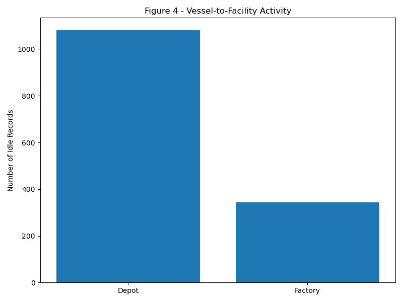
Figure 4 reduces the comparison to overall facility-linked activity. Depots account for 1,080 idle records and factories for 343, a ratio of roughly three to one. Combined, the two contexts contain 1,423 points, or 23.5% of all idle activity during May and June.
Depot activity is the steadier side of that relationship. Its total is only 32 points below the March-April level, reinforcing the role of depots as recurring return points for supplies, crew changes, technical support, standby positioning, and repair mobiliza-
Figure
ASK THE EXPERT
Question for the author(s)? Click here!
tion. Those needs persist across different phases of the fleet cycle.
Factory activity falls more sharply, from 518 points in March-April to 343 in May-June, a decline of 33.8%. Factories remain important staging locations for cable loading and departure, but their signal is narrower and more campaign-dependent. In this period, the nearby activity is more often unclassified than installation-linked.
The combined facility share also moves lower, from 37.7% of March-April idle points to 23.5% in MayJune. That difference helps explain why the larger fleet picture feels less defined. The recurring depot anchor is still visible, but a greater portion of activity sits outside the two facility contexts highlighted here.
A WIDER PATTERN, A MORE CAUTIOUS READING
May-June does not repeat the structured spring profile described for March and April. Idle activity is 40.2% higher, yet the two identifiable operating categories occupy a much smaller share of the whole. The fleet’s geographic reach remains broad, but
the link between pauses and recognizable maintenance or installation patterns is weaker.
The clearest continuity is the depot network. Depot-linked totals hold close to their prior level, and maintenance remains the leading depot classification. The clearest change is around factories, where overall activity declines and unclassified points become the majority. These shifts describe the period without establishing a single cause for it.
AIS activity always benefits from restraint in interpretation. A pause can reflect operational work, waiting, weather, port constraints, routing, or other circumstances that position data alone cannot resolve. The large unclassified share is therefore part of the story: it marks the limit of what the activity pattern can say with confidence.
The distinction between presence and task definition is important. A vessel can be visible within a major cable basin, moving along a familiar route or pausing near established infrastructure, without the surrounding pattern clearly indicating the phase of work. In May-June, the global spread confirms that the fleet remains engaged across the network. The lower facility-defined share, however, means geography offers less help in separating active assignments, readiness, staging, and other pauses. Reach is therefore the strongest signal; purpose is less consistently visible.
Depot continuity provides a useful baseline within that ambiguity. The concentration of activity around depots keeps the maintenance network legible even when the wider map becomes harder to classify.
Factory activity is different because it occupies a narrower share of the facility-linked pattern rather than serving as a constant fleet-wide anchor. When that factory signal narrows, the map can remain geographically busy while showing fewer concentrated signs of installation work. The operational picture is not empty; it is uneven, with durable support behavior at depots and more intermittent definition elsewhere.
Figure 3: Activity by Infrastructure Type (May-June 2026)
By the end of June 2026, the cable-ship fleet appears globally engaged but operationally diffuse. Maintenance remains the strongest identifiable mode, installation is present at a smaller scale, and depots continue to provide the most stable infrastructure signal. Yet the dominant feature of May-
June is the space between those categories: more activity overall, with less of it clearly defined.
Kieran Clark is Senior Analyst at Submarine Telecoms Forum, Inc. He joined in 2013 as a Broadcast Technician supporting live event streaming, bringing over eight years of production experience. Promoted to Analyst in 2014, he now leads research and maintenance for the SubTel Forum Submarine Cable Database and Online Map, with analysis featured across most SubTel Forum publications.
THE BARAT-TIMUR INDONESIA 1 (BTI1) SUBMARINE CABLE SYSTEM
by John Maguire
INTRODUCTION
As an archipelagic nation comprising more than 17,000 islands, some 10,000 of them inhabited by the population of almost 290 million1, Indonesia is understandably heavily dependent on undersea cable connectivity to carry domestic as well as international telecom traffic.
The country is generally well-connected, with more than 50 submarine cables having announced RFS between 2003 and 2025 (of which 23 are international) and another 11 with RFS planned in the future (of which six have an international connection)2 . Indonesia’s geography is such that, apart from domestic inter-island systems, it can connect to the key regional economies of Singapore and Malaysia, as well as to neighbours, Timor-Leste and Papua New Guinea—with each of whom it shares an
island—using relatively inexpensive unrepeatered undersea cables. Moreover, as an important market in its own right, and with its massive extent and strategic southeast Asian location, Indonesia also sees significant international cable development activity in and through its waters, especially as an alternative to the currently risky regulatory environment of the South China Sea.
Among larger domestic systems planned to be delivered are the BTI1 and BTI2 cables being developed by PT Super Sistem Data (Super Sistem), the former of which is the central subject of this article. Also relevant to our consideration is Super Sistem’s proposed Batam-Singapore cable, SSBS3
BTI-1 OVERVIEW
Barat-Timur Indonesia-1 (BTI1) is a privately owned, high-fibre-count cable system spanning—as its name would suggest4—the breadth of Indonesia. Under development by Super Sistem, it will con-
Figure 1: Screengrab of Indonesia’s domestic and international submarine cables, in service and planned3
4 The Indonesian ‘Barat-Timur’ translates to West-East in English.
nect more than 4,400 km5 between the designated Indonesian super gateways6 of Batam in the west and Manado in the east, landing en route in the key centers of Jakarta (Tanjung Pakis) and Surabaya (Gresik) in Java, Makassar in southern Sulawesi, and Balikpapan in East Kalimantan, close to Indonesia’s proposed new capital city, Nusantara.
The system is planned as a point-to-point trunk with branches rather than, as with many Indonesian systems a closed (or even open) domestic festoon or ring. The principal Batam-Jakarta-Manado axis links Indonesia’s western (pointing towards nearby Singapore and onwards towards Europe) and eastern (pointing at the Philippines and onwards to the Pacific) international gateways with the capital city, which is not itself the location of a designated gateway.
BTI1, designed in the open cable model7, will comprise 24 fiber pairs, with 16 designated for express links between the Batam and Manado national gateways, and eight serving the other major centers. It is a repeatered, space-division-multiplexed (SDM) system, with wavelength-selective-switch reconfigurable optical add/drop multiplexing (WSS-ROADM) and enhanced branching units8. This is state-of-the-art carrier and hyperscaler infrastructure—obviously intended to be employed in high-capacity wholesale and backbone connectivity. The feasibility study for the proposed cable was delivered with the support
of a grant from the United States’ Trade development Agency, USTDA9 .
BTI1 dovetails with its sister systems, SSBS and BTI2. SSBS extends both BTI systems to Singapore whereas BTI2, following on closely from and emulating BTI1, will again connect Batam to Manado but with landings in eight additional regional centres, adding reach and resiliency to Indonesia’s national infrastructure and to Super Sistem’s network.
DOMESTIC SYSTEMS CONTEXT
“BTI1 represents a new generation of Indonesian subsea infrastructure, linking the nation’s western and eastern gateways with high-capacity, open-cable architecture designed for resilience, scalability, and regional growth.”
Indonesia, as we have seen, has—and needs—a wealth of submarine connectivity. While a precise total measure of overall connectivity is difficult to pin down because sources count systems, cables, corridor segments and routes differently, An Indonesian government study in 2023 counted 56 systems whose routes totalled 115,104 km, including 55,069 km within Indonesia’s 200 km exclusive economic zone (EEZ) 10. Using TeleGeography’s more readily accessible resources, we see there are 42 in-service and planned domestic submarine cable systems. Of these, no fewer than nine are short (<200 km) point-to-point systems connecting just two islands. Another three cables, from about 400-900 km long, connect points on a single island, e.g., Sulawesi’s point-to-point Luwuk Tutuyan Cable System (LTCS) at 446 km, and Java’s unrepeatered11 festoon con-
5 https://supersistem.id/cables/bti-1/
6 This term, employed by Super Sistem, refers to the international landing station sites specified in the Decree of the Minister of Maritime Affairs and Fisheries Number 14 of 2021 concerning Undersea Pipelines and/or Cables, available for download at https://jdih.kkp.go.id/Homedev/DetailPeraturan/3006
necting Jakarta and Surabaya with additional landings near Cirabon and Semarang, spanning a total 888 km.
Otherwise, as the map at Figure 2 shows, many of the more comprehensive domestic systems, such as the Palapa Ring West, -Middle, -East trio, for example, interconnect clusters of more adjacent islands in Indonesian sub-regions, extending reach and aggregating traffic volumes. The Palapa cables are built under the public-private partnership (PPP) model, responding to both a universal service and a commercial need. These PPP packages connected 57 commercially unattractive districts. The Ministry of Communication and Digital Affairs (Komdigi) put these packages at 12,229 km of fibre, of which 8,073 km is submarine, and 55 terrestrial radio links in its 2024 performance report12
BTI1, connecting directly from Batam to Manado, as also shown in Figure 2, is clearly differentiated from the cables of both these categories.
While not strictly a domestic system, because of its landing in Singapore, Telin’s 5,300 km Indonesia Global Gateway (IGG) must be mentioned in this context, as the closest strategic comparator to
BTI1. In service since 2018, its four fiber pairs connect Dumai in the west, with Batam, Jakarta, Madura, Bali, Makassar, Balikpapan, Tarakan and Manado in the east, as well as Singapore. This system is explicitly described as a bridge between a Europe-facing cable landing at Dumai and a US-facing system at Manado13. IGG thus already performs the west-toeast aggregation and international interconnection that BTI-1 seeks to build upon.
BTI-1’s differentiators here are less in regard of its routing, the broad corridor having precedent, but BTI1 materially advances the model through its optical level flexibility, significantly higher fiber count and its open wholesale proposition.
LEGAL AND REGULATORY CONTEXT
Indonesia’s regulatory framework for submarine telecommunications cables has become increasingly structured over the past decade, reflecting the government’s objectives of strengthening digital sovereignty, improving marine spatial planning, and reducing conflicts between subsea infrastructure and other maritime users.
A defining feature of the current regime is the establishment of designated submarine cable corri-
dors, including beach manhole locations, and international gateways14. The regulation is intended to minimise conflicts with fishing, shipping, pipelines, and environmentally sensitive areas, and to provide greater certainty for future infrastructure investment. This corridor-based approach—which is subject to additional requirements in respect of operating experience and minimum Indonesian investment—has become a central element of Indonesia’s subsea cable policy and reflects the government’s desire to move towards a more orderly model, comparable to Singapore’s15 .
Apart from the relatively recently adopted corridor approach, developers in Indonesia must also navigate both the country’s implementation of several aspects of the United Nations Convention on the Law of the Sea (UNCLOS)16 and its cabotage laws—two separate issues that are closely intertwined.
sets rigorous conditions for such access. ASEAN’s recent non-binding “Enhanced ASEAN Guidelines for Strengthening Resilience and Repair of Submarine Cables”, issued in January this year18, now urge single points of contact, simpler repair permits and cabotage exemptions for cable vessels. Malaysia has already exempted cable ships from cabotage19—Indonesia has yet to so.
“BTI1 advances Indonesia’s westto-east connectivity model through greater optical flexibility, higher fiber count, and an open wholesale structure designed to strengthen national reach, resilience, and international interconnection.”
While UNCLOS preserves freedom to lay and maintain cables in an EEZ and on a continental shelf, subject to due regard and reasonable coastal-state resource measures, Indonesia’s archipelagic waters complicate this differentiation17, and Indonesia
The degree of difficulty attaching to achieving approval to install and repair submarine cables in Indonesia and its waters are demonstrated by the cases of the long and continuing delay delivering the Echo and Apricot cables, and the recent delayed repair in 2024 of SMW520. Apricot was initially announced by Google with a 2024 RFS target21. This has slipped, according to PLDT, to 202722. Likewise, Echo was initially announced by Google with a 2023 expected RFS date23. Since that time, Meta, in October 2025, announced that Echo was already delivering “260 Tbps of capacity between Guam and California, with options for onward connectivity into Asia in the future”24. Given XL Axiata announced the system’s landing at Tanjung Pakis, near Jakarta,
22 https://bilyonaryo.com/2025/04/01/on-track-for-2027-completion-pldts-80m-apricot-cable-system-toincrease-intl-capacity-by-33/technology/ (No more recent announcement has been found).
in June 202225, it is unclear what is causing the continuing delay in declaring system-wide RFS.
Perhaps benefitting from plans that were less advanced prior to the issue of the Minister of Maritime Affairs and Fisheries Decree Number 14 of 2021, Super Sistem announced corridor approval in September 2025 and has said that a detailed marine survey would precede installation26. In achieving this milestone, Super Sistem leads the way in showing that the routing approach in respect of these cables, of
"BTI-1 could become one of Indonesia’s most strategically important privately developed domestic submarine cable systems by improving resilience, supporting digital transformation and creating an alternative national transport corridor"
using Indonesia as an alternative to the South China Sea, with its regulatory jeopardy, may be maturing.
CONCLUSION: BTI1’S KEY PROPOSITIONS
BTI-1 captures Indonesia’s central policy bargain in what is designed to be a commercially attractive package. The country wants sovereign control, orderly seas, domestic maritime capability and more value retained at home. BTI-1’s Indonesian ownership and approved corridor make it politically well aligned, while its Batam-Jakarta-Manado geometry turns domestic inclusion into international route diversity. Moreover, its high fiber count and the already announced follow-on system, BTI2, point to a means for new transpacific systems that wish to reach Singapore and points west of there, to do so without necessarily having to build an Indonesian segment immediately.
systems by improving resilience, supporting digital transformation and creating an alternative national transport corridor between western and eastern Indonesia. BTI1 will modernise and diversify Indonesia’s already substantial submarine cable network. It represents an important new generation of open, wholesale-focused submarine infrastructure in Indonesia.
John Maguire is Director, EMEA at APTelecom, with 30 years of telecommunications experience across global markets. He has sold security and network-control software, built regional federation fibre networks, and established interconnect and wholesale structures in emerging markets. His career spans OEMs and service providers, fixed and mobile domains, and roles in general management, sales, operations, and business development. Based in Dublin, he has worked worldwide.
Assuming successful execution, BTI-1 could become one of Indonesia’s most strategically important privately developed domestic submarine cable dates-to-our-asia-pacific-connectivity-projects/ 25 https://subtelforum.com/echo-cables-golden-bouy-has-landed-in-tanjung-pakis/ 26 https://subtelforum.com/super-sistem-aptelecom-advance-bti-cable-system/
6 QUESTIONS WITH ADAM BALL: TALKING SUBMARINE GENERAL MANAGER AT SUBMARINE NETWORKS WORLD
1. Why is Submarine Networks World 2026 expected to be the largest and most significant edition to date?
Submarine Networks World has become the premier annual gathering for the global subsea communications industry, and its 2026 edition will be the largest yet. Expanded programming, a record speaker lineup, and a dedicated security conference reflect the industry’s growth and the strategic importance of submarine cable infrastructure.
Submarine Networks World 2026 will welcome more than 1,500 subsea fibre leaders and 150+ industry speakers from around the globe to the Sands Expo & Convention Centre in Singapore on 23-24 September 2026.
The new Subsea Security World theatre will bring together security specialists, government agencies, navies, coast guards, policymakers, regulators, and academics from the Americas, Europe, Asia, and Oceania to address the industry’s leading concern.
2. What prompted the launch of Subsea Security World, and why has subsea cable security become such a critical industry priority?
Governments and operators increasingly recognize submarine cables as critical national infrastructure, making resilience and security central industry concerns. Geopolitical developments, cable-protection risks, and growing international cooperation have created demand for a forum where commercial and public-sector stakeholders can develop practical solutions.
Subsea Security World addresses these issues by bringing together defence organizations, policymakers, regulators, cable owners, operators, suppliers, and researchers to discuss protecting the world’s subsea communications infrastructure.
3. Who should attend Submarine Networks World x Subsea Security World 2026?
The conference brings every part of the submarine cable ecosystem together. Cable owners and operators, consortium members, technology providers,
innovators, consultants, service partners, government entities, financiers, and survey companies will be onsite, creating a one-stop shop for those planning, financing, designing, constructing, operating, maintaining, or protecting cable systems. Attendees can pursue business opportunities, technical knowledge, investment partners, and policy insights while meeting the organizations shaping global connectivity.
4. Which companies, organizations, and industry leaders will be participating?
More than 80 sponsors, exhibitors, and partners will showcase subsea technologies, products, and services. Delegates will hear from 150+ influential speakers representing every inhabited continent.
Keynote speakers include:
• Sean Bergin, President & Co-Founder, APTelecom
• Nadia Krivetz, Director, Cable Resilience & Connectivity Centre, DFAT Australia
• Sasha Pearson, Policy Analyst, European Centre for Development Policy Management (ECDPM)
• Jim Fagan, Chief Executive Officer, EXA Infrastructure
• Robert Pepper, Senior Fellow, Global Digital Inclusion Partnership
• Kent Bressie, Partner, HWG LLP and Legal Advisor, ICPC
• Woon Sien Loh, Senior Director, Infrastructure Planning & Market Development, Info-Communications Media Development Authority (IMDA)
• Andy Palmer-Felgate, Submarine Cable Engineer, Meta
CABLE INDUSTRY WITH TERRAPINN’S WORLD X SUBSEA SECURITY WORLD 2026
frastructure
• Bevan Slattery, Founder, SUBCO
• Alan Mauldin, Research Director, TeleGeography
• Nelson McMillan, Assistant Defence Attaché, British High Commission, Singapore and UK–Asia Pacific Maritime Strategy Expert, UK Ministry of Defence
5. What topics will be covered during the conference?
The programme combines strategic business discussions with deep technical content and the latest developments affecting the global subsea sector. Each morning begins with keynote presentations before delegates move into specialist theatres covering:
• Strategy
• Cable Systems
• Data Centres & Cable Landing Stations
• Networks
• Operations & Maintenance (O&M)
• Subsea Security World
Together, these sessions examine infrastructure investment, cable deployment, network operations, maintenance strategies, data centre connectivity, emerging technologies, policy developments, and the growing importance of subsea infrastructure security.
6. How can industry professionals register and receive a discount?
For complete event information and the full conference agenda, visit: www.terrapinn.com/ExploreSNW. SubTel Forum readers can receive 10% off conference passes by entering the promotional code SUBTEL10 during registration.
ADAM BALL is General Manager of Terrapinn responsible for the management of Submarine Networks World since 2018. He is an experienced sales leader with a proven track record in both London and Singapore. Coupling an affable nature with outstanding influencing and communication skills, he has directly formed and maintained long-term business relationships of integrity and success across a variety of high value/high profile products and services.
ABOUT TERRAPINN Terrapinn has been sparking ideas, innovations and relationships that transform business for over 30 years. Using our global footprint, we bring innovators, disrupters and change agents together, discussing and demonstrating the technology, strategies and personalities that are changing the way the world does business. Whether you’re looking to make new connections, introduce a product or inspire change in your industry, we invite you to join us as agitators of change. Terrapinn – spark something.
AGENDA / DAY 1
Synchronizing subsea security and putting policy into practice - who does what, when, why and where? (by invitation only)
Andy Palmer-Felgate; Giuseppe Valentino; Nelson McMillan; Kent Bressie; Nadia Krivetz
Sean Bergin
Pushing the end-to-end delivery of subsea cables (permit permitting of course) Carine Romanetti; Anjali Sugadev; Hany Zaalok; Loizos Economides MODERATOR: Byron Clatterbuck
SMART | 15:40-16:20
Bertrand Clesca
15:40 Subsea cable sensing and the ocean environment Dr. Dora Juan Juan HU
16:00 Speaker spotlight Raoul Jacquand
16:20 PANEL
Building the business case for SMART - the commercial question mark continues? Andrew Parsons; Josh Munro
MODERATOR: Laurent Campagne
Ahuja; Majed Almaghlouth
MODERATOR: Corrine Teng
14:00 Raising 'awareness' - is your cable next on the chopping block RAdm Roy Vincent Trinidad
Clocking Conflict - from fishing boats to sabotage, caring for your cable through monitoring
Heiner Ottersberg; Mark Englund; Anders Tysdal; Dean Veverka
MODERATOR: Alasdair Wilkie
15:40 Subzero Subsea - cable armouring and protection challenges in Arctic conditions Jonny Lundin
16:00 Sponsor Presentation
16:20 PANEL
Landing points - the 'Achilles Heel' of subsea cable systems
Vlad Ihora; Adrian Moss; Douglas Njenga; Hazzaa Alhazzaa
MODERATOR: Oli Pope
AGENDA / DAY 2
Nadya Melic; Philippe Recco; Rosalind Thomas; Tansy McCluskie
Network resilience - diversity and inclusion as the path to zero downtime Ana Nakashidze; Farhan Mohamed Bouh; Andy LaBrunda; Sponsor Seat
MODERATOR: Rebecca Nottingham
SYMBIOTIC ACCELERATION: WHY CONNECTIVITY IS BECOMING
AS IMPORTANT
AS POWER IN THE AI ERA
By Joel Ogren
Artificial intelligence is reshaping the digital infrastructure landscape at a pace few could have predicted just a few years ago.
Headlines often focus on GPUs, hyperscale campuses, and the race among technology companies to develop increasingly sophisticated AI models. Yet the true story of the AI era extends well beyond processing power.
Behind every AI application sits an interconnected network of power generation, data centers, cooling technologies, terrestrial fiber networks, submarine cable systems, cloud platforms, and communications infrastructure. As demand increases in one area, investment follows across the others. The result is a self-reinforcing cycle in which investments create opportunities for additional growth across the broader digital economy. This phenomenon can best be described as symbiotic acceleration, a concept the author introduced during a keynote presentation at the recent Submarine Networks EMEA conference in London to describe how AI is
driving investment across every layer of digital infrastructure.
More power supports larger AI deployments. Growing demand requires additional connectivity. Expanded connectivity attracts data centers, cloud platforms, and new digital services. Each component reinforces the others.
As AI adoption accelerates worldwide, this dynamic is changing how networks, facilities, and supporting resources are planned, financed, and deployed. For the submarine cable industry, the implications extend far beyond increased bandwidth demand. AI is reshaping the relationship between connectivity, power, data centers, and economic development, creating new opportunities and challenges across the global digital economy.
AI IS CHANGING INFRASTRUCTURE PLANNING
The first wave of AI investment focused primarily on building larger and more powerful technology platforms. Today, the conversation has expanded significantly. AI workloads require unprecedented levels of power density, cooling capacity, and network
performance. Rack power requirements that once averaged 10 to 20 kilowatts are increasing to reach 80, 100, or even 140 kilowatts and beyond. Global data center electricity consumption is expected to rise substantially over the coming decade as AI adoption continues to expand across industries.
What makes this growth different from previous technology cycles is that AI demand cannot be satisfied through data center expansion alone.
Power must be available to support higher-density environments. Cooling systems must evolve to manage increased thermal loads. Terrestrial fiber networks must transport larger volumes of data between facilities. Submarine cable systems must support growing international traffic requirements. Each element plays a critical role in enabling AI applications at scale.
As a result, investments are becoming interconnected. Decisions about power, connectivity, and facility development can no longer be made independently. Each influences the success of the others.
In many markets, the conversation has already shifted from “Where can we build?” to “Where can we build with access to power, connectivity, resiliency, and long-term scalability?” The answer determines which regions will emerge as future digital infrastructure hubs.
CONNECTIVITY BECOMES A STRATEGIC RESOURCE
Much of the public discussion surrounding AI infrastructure focuses on power. While power availability remains critical, connectivity is rapidly emerging as an equally strategic resource.
Modern AI applications depend on the movement of enormous volumes of data. Training datasets often reside across multiple geographic regions and cloud
environments. Models require synchronization across locations, and enterprises expect low-latency access to AI services regardless of where those resources are physically located.
Meeting these requirements demands a highly connected ecosystem. Within data centers, advanced networking technologies move information between processors, storage platforms, and applications. Between locations, terrestrial fiber routes transport growing volumes of traffic. Across oceans, submarine cable systems provide the foundation for global communications.
These networks enable data to move efficiently between users, applications, cloud environments, and AI resources regardless of
geography. Without them, even the most advanced deployments remain isolated from the broader digital economy.
This reality is influencing planning decisions around the world. Developers increasingly evaluate network access alongside power availability when selecting locations for future development. Diverse terrestrial fiber routes, proximity to major network exchanges, and access to international cable systems are becoming key differentiators.
A market may possess abundant energy resources, but without strong network connectivity its ability to participate in the AI economy remains limited. The most successful regions will be those capable of delivering both
POWER AND COOLING REMAIN FOUNDATIONAL
Power remains the heartbeat of the AI ecosystem.
To support growing AI workloads, operators are pursuing a variety of approaches, including utility-scale grid connections, battery storage systems, on-site generation resources, fuel cells, and long-term renewable energy agreements. More efficient power distribution systems are also being deployed to support dense environments.
Cooling technologies are evolving alongside power systems. Traditional air-cooling approaches are being supplemented by direct-to-chip liquid cooling, immersion cooling, rear-door heat exchangers, and other advanced thermal management solutions capable of supporting modern AI deployments.
The relationship between power, cooling, and connectivity illustrates the interconnected nature of today’s digital ecosystem. Higher-density environments require more power and more cooling. Those same environments generate greater data flows that depend on sophisticated network infrastructure.
Each layer supports the others. Improvements in one area create opportunities for advancement in another, reinforcing the cycle of symbiotic acceleration.
TERRESTRIAL FIBER: ENABLING REGIONAL AI ECOSYSTEMS
Terrestrial fiber networks serve as the regional arteries of the digital economy, connecting data centers, cloud platforms, enterprises, and end users.
As AI adoption accelerates, these networks are becoming essential to supporting future growth. Providers continue to deploy high-fiber-count cables, dense route architectures, and scalable designs capable of supporting rising demand.
Their value extends well beyond bandwidth. Access to diverse routes has become a critical factor in planning future development. Data center operators now view network access as a prerequisite for expansion. A market may possess abundant power resources, but without strong connectivity its ability to participate in the AI economy remains limited.
These networks also play an essential role in resiliency. Route diversity improves reliability, provides redundancy, and supports business continuity requirements that are becoming just as critical as AI is integrated into mission-critical operations.
Perhaps most importantly, terrestrial fiber helps transform individual facilities into regional digital ecosystems. By linking data centers, enterprises, cloud platforms, and cable landing stations, it creates the foundation for broader economic and technological development.
As new routes are deployed, they often attract additional investment from cloud providers, enterprises, and developers. What begins as a network expansion project frequently becomes a catalyst for new business activity, digital services, and long-term regional growth.
SUBMARINE CABLES: THE FOUNDATION OF GLOBAL AI INFRASTRUCTURE
While terrestrial fiber supports re-
gional communications, submarine cable systems provide the international reach required to support modern AI applications.
More than 99 percent of international internet traffic travels across subsea networks. These systems connect continents, support cloud platforms, enable global commerce, and facilitate the exchange of information that powers the digital economy.
AI is increasing the importance of these networks. Training workloads, cloud services, enterprise applications, and users are distributed across regions and continents. The ability to exchange information efficiently between locations is becoming critical to both operational performance and business competitiveness.
This helps explain why hyperscalers have become major investors in submarine cable systems. Organizations such as Google, Meta, Microsoft, and Amazon recognize that connectivity is no longer simply a supporting service. It is a critical enabler of cloud growth, digital services, and international data exchange.
Recent investments in new cable systems reflect this trend. Projects spanning multiple continents are being designed with unprecedented capacity, supporting levels of traffic that would have been difficult to imagine only a decade ago.
For the submarine cable industry, AI represents more than a new source of demand. It reflects a fundamental shift in how these networks are viewed within the digital economy. Their ability to connect markets, support cloud expansion, and enable seamless information exchange is becom-
ing central to the next phase of technological growth.
THE EVOLUTION OF CABLE LANDING STATIONS
Few assets illustrate the convergence of connectivity, cloud services, and AI more clearly than the cable landing station.
Historically, cable landing stations served a straightforward purpose: connecting submarine cable systems to terrestrial net-
works. While that role remains essential, these facilities are becoming more strategic as demand for global connectivity continues to grow.
As AI adoption expands, cable landing stations are evolving beyond simple network endpoints. Their proximity to international connectivity, terrestrial fiber routes, and interconnection ecosystems makes them attractive locations for additional services
and investment.
Depending on the market, this may include edge computing resources, AI inference environments, cloud connectivity platforms, satellite communications capabilities, network interconnection services, and other applications that benefit from direct access to global networks.
This evolution reflects a broader shift occurring throughout
the industry. Power, connectivity, cloud platforms, data centers, and digital services are no longer planned independently. Instead, they are increasingly viewed as interconnected components of a larger ecosystem. Cable landing stations sit at the intersection of these capabilities, making them natural gateways for regional growth and digital expansion.
Their strategic value extends well beyond network access. In many regions, cable landing stations have the potential to influence where future investment occurs.
A new landing station can create opportunities for terrestrial fiber expansion, attract cloud and content providers, encourage data center development, and support broader economic growth.
As organizations seek locations that offer both connectivity and long-term scalability, these facilities can serve as anchors for future development. For operators, investors, and local communities, cable landing stations are becoming more than connectivity assets. They are emerging as strategic platforms that help attract investment, strengthen regional capabilities, and enable greater participation in the AI economy.
THE INFRASTRUCTURE FLYWHEEL
The concept of symbiotic acceleration is perhaps best understood through what can be described as an infrastructure flywheel.
What makes AI different from previous technology cycles is that investments across the digital landscape increasingly reinforce one another. A single project rarely remains isolated for long. Instead, it often becomes the catalyst for additional development through-
out the broader ecosystem.
A new submarine cable landing can attract terrestrial fiber investment. Expanded connectivity can support data center development. New data centers increase demand for power generation and transmission. Enhanced capabilities attract cloud providers, enterprises, and digital services. Economic growth generated by those investments creates additional demand for connectivity, capacity, and supporting resources.
The result is a self-reinforcing cycle where each investment strengthens the value of the next.
Development no longer occurs as a series of independent projects. Increasingly, investments in power, connectivity, and data center capacity reinforce one another, creating ecosystems that attract additional growth. Regions that successfully combine connectivity, power availability, land resources, and supportive regulatory environments are often better positioned to attract long-term investment and participate in the next phase of digital growth.
This dynamic is becoming more visible around the world. Markets that once competed primarily on location or energy costs are now differentiating themselves through the strength of their digital ecosystems. Access to power remains important, but so does access to terrestrial fiber, international connectivity, cloud onramps, and interconnection opportunities.
The flywheel effect also extends beyond physical assets. As connectivity improves and digital capabilities expand, regions become more attractive to tech-
nology companies, research institutions, cloud providers, and enterprises seeking to leverage AI capabilities. This creates additional economic activity, supports workforce development, and encourages further investment across the ecosystem.
AI is accelerating this trend by increasing the value of integrated strategies. Success is no longer defined solely by the performance of individual assets. It is also determined by how effectively power, connectivity, data centers, and digital services work together to support growth, resiliency, and innovation.
RESILIENCY BECOMES A STRATEGIC IMPERATIVE
As AI becomes embedded within healthcare systems, government operations, financial services, manufacturing environments, and communications networks, resiliency becomes more important that ever.
Organizations are placing greater emphasis on route diversity, redundant power systems, multiple connectivity paths, and geographically distributed deployments. The objective is not simply to improve performance. It is to ensure continuity.
The same principles that have guided mission-critical communications networks for decades are becoming increasingly relevant to the broader AI ecosystem. A resilient AI environment requires more than scale. It requires infrastructure capable of supporting continuous operations under a wide range of conditions.
This places even greater importance on diverse terrestrial and submarine connectivity. As AI becomes more deeply integrated
into critical services, connectivity failures become business failures. Resiliency is no longer simply a technical requirement. It is a strategic necessity.
BUILDING THE FOUNDATION FOR THE AI ECONOMY
The AI boom is often described as a race for technology leadership. In reality, it is driving something much larger.
Power systems, terrestrial fiber networks, submarine cable systems, cable landing stations, data centers, cloud platforms, and communications networks are becoming increasingly interconnected. Investments in one area create demand and opportunity in others, resulting in a cycle of growth that extends across the broader digital economy.
This is the essence of symbiotic acceleration.
The organizations that succeed in the years ahead will not be those that optimize a single component of the technology stack. They will be those that understand how connectivity, power, cloud platforms, and digital services reinforce one another. The future belongs to interconnected ecosystems, not isolated assets.
As terrestrial and submarine networks continue to expand, they will serve as the foundation that links people, businesses, applications, and markets around the world, enabling the next generation of innovation and economic growth.
Joel Ogren is Chief Executive Officer of Assured Communications, which he founded in 2013. With over 38 years in information and communications technology, he has supported US federal agencies, led the Center for National and Nuclear Leadership Command Capabilities, and held senior roles at Ocean Networks, GoTo Networks, the University of Hawai'i, and Johns Hopkins APL. He holds an MS from the US Naval Postgraduate School.
INTEGRATED FIBER OPTICS: SUPPORTING SUSTAINABLE ENERGY, OFFSHORE WIND AND THE GLOBAL TRANSITION TO RENEWABLES
By Tobias Borg
An offshore wind export cable can stretch for hundreds of kilometres across the seabed and remain in service for decades.
Once installed, these assets are effectively inaccessible for visual inspection and physical access is extremely limited. Their location on or beneath the seabed means that any form of direct monitoring or intervention requires specialised vessels and equipment. When faults occur, locating and repairing them can take time, and the associated loss of power transmission can be significant, particularly where large volumes of generated energy depend on a single export route.
For this reason, modern high-voltage subsea cables increasingly incorporate optical fibre within their structure. The fibre provides a data pathway and enables the cable to report on its condition through a range of monitoring techniques. As offshore wind farms expand in scale and distance from shore, and as high-voltage interconnectors link power systems across longer distances, this capability is be-
coming increasingly important in supporting system operation and oversight.
A DUAL-PURPOSE DESIGN
Optical fibre is integrated directly into high-voltage AC or DC cables during manufacturing as part of the cable construction process. The fibre is typically housed within a hermetically sealed stainless-steel tube, positioned either at the centre of the cable or within the conductor structure itself. This positioning allows the fibre unit to be incorporated without altering the fundamental electrical design of the cable.
The tube protects the fibres from mechanical stress, environmental exposure, and interaction with other cable components. This design enables a single cable to carry both electrical power and data within the same physical structure. The fibre unit is embedded during production, ensuring that its presence does not compromise the electrical or mechanical performance of the power cable, and that it remains protected throughout handling, installation, and operation. Inside the tube, the fibres are free to move within a thixotropic water-blocking
Cross-section of a submarine optical cable for integration
Submarine optical cable part based on a hermetically sealed stainless tube. Inside the tube, the fibers are free to move within the thixotropic water-blocking compound. The steel tube is protected by a semiconductive polyethylene jacket.
compound. This compound prevents water ingress and supports the fibres by cushioning them against movement and vibration. The steel tube itself is protected by a semiconductive polyethylene jacket, which provides an additional layer of protection and compatibility with surrounding cable materials.
Fibres are colour-coded to support identification during installation, splicing, and maintenance
activities. This simplifies handling during complex offshore operations where multiple fibres may need to be accessed and managed simultaneously. Fibre units designed for this application can accommodate multiple fibres within a single tube, supporting both communications and sensing applications within the same cable system. This allows a single integrated solution to fulfil several operational functions.
ENGINEERING FOR HARSH ENVIRONMENTS
The conditions inside high-voltage subsea cables are demanding and require careful engineering consideration. These systems are exposed to hydrostatic pressure at depths of up to 2,000 metres, elevated operating temperatures associated with power transmission, longitudinal forces during installation, tight bending radii as cables are routed and laid, and ongoing thermal cycling over their operational life.
Each of these factors has the potential to affect both the electrical and optical components of the cable. As a result, the fibre unit must be designed to operate reliably within this environment without degradation of performance.
To withstand these conditions, integrated fibre units are engi-
neered with specific design features. The stainless-steel tube isolates the fibres from mechanical and thermal stresses within the conductor, helping to maintain stable operating conditions for the optical elements. Water-blocking materials, including gels and dry elements, prevent longitudinal water ingress if the outer cable jacket is damaged.
Maintaining optical performance under these conditions is essential for both communication and sensing functions. The materials and construction of the fibre unit are designed to minimise attenuation and preserve signal integrity under pressure, temperature variation, and mechanical loading. This ensures that the optical pathways remain functional throughout the operational life of the cable.
COMMUNICATIONS BACKBONE FOR OFFSHORE ENERGY
Offshore wind farms require reliable communication between turbines, offshore substations, and onshore facilities to support their operation. This includes supervisory control and data acquisition (SCADA), protection signalling, and condition monitoring systems that enable operators to manage and control the generation and transmission of power.
integrated approach is also used in high-voltage interconnectors, where embedded fibre supports communication and control functions over long distances between connected grids. In these applications, maintaining consistent and reliable data transmission is essential for coordination between systems.
DISTRIBUTED SENSING ALONG THE CABLE
In addition to communications, embedded optical fibre can act as a continuous sensing element along the full length of the cable when connected to an interrogator system. This enables the cable to provide information about conditions along its route, rather than only at discrete points. Several sensing techniques are in routine use, each based on different optical scattering principles within the fibre.
• Distributed temperature sensing (DTS) uses Raman backscatter to map temperature along the cable, so operators can find hotspots and prevent thermal overload.
• Distributed acoustic sensing (DAS) uses Rayleigh backscatter to detect vibration, identifying trawler interaction, anchor strikes, and seabed movement in real time.
• Distributed temperature strain sensing (DTSS) uses Brillouin to detect fatigue, slippage, and seabed erosion before they affect the cable’s long-term stability.
Together, these techniques allow the optical fibre to function as a distributed monitoring system, providing continuous insight along the entire length of the cable. GJL Submarine
By embedding optical fibre within the export cable, operators can establish this communications link without installing a separate telecommunications cable along the same route. This reduces the need for additional infrastructure and ensures that communications follow the same route as the power transmission system, simplifying overall system design and installation. This
DESIGNING FOR SENSING PERFORMANCE
The performance of distributed sensing depends on how the fibre interacts with the surrounding cable structure. One of the key parameters in this context is fibre coupling, which determines how physical changes in the cable are transferred to the optical fibre. When temperature measurement is the primary requirement, fibres may be loosely coupled within the tube to minimise the transfer of mechanical strain. This allows temperature to be measured independently of mechanical effects. When strain sensing is required, tighter coupling allows mechanical forces to be transferred more directly to the fibre and detected as changes in the optical signal. This enables the measurement of strain along the cable.
Achieving the desired sensing performance requires careful selection of fibre coatings, tube design, and mechanical interfaces. These factors must be balanced to ensure that the fibre provides accurate measurements while maintaining long-term durability within the cable environment.
BEYOND THE FIBRE UNIT
The performance of the optical system depends not only on the fibre unit within the cable but also on the components used to connect, protect, and manage it throughout the system.
Joint closures maintain fibre integrity at splice points, ensuring that optical continuity is preserved where cable sections are connected. Termination systems manage the transition between subsea cables and onshore or offshore installations, providing
controlled interfaces for both power and fibre elements. Microduct systems allow fibres to be routed within joint housings in a structured and protected manner. Installation tooling and training support consistent handling during manufacturing and deployment, helping to ensure that the fibre is not damaged during these processes. Each of these elements contributes to the overall performance and reliability of the optical system within the cable.
SUPPORTING EXPANDING ENERGY NETWORKS
Integrated optical fibre is used across offshore wind farms, submarine interconnectors, and onshore grid systems as part of modern energy infrastructure. In offshore wind, it supports communications, control, and condition monitoring. In interconnectors, it provides data links required for system operation and coordination. Onshore, similar technology is used in grid and infrastructure applications where monitoring and communication are required alongside power transmission.
Hybrid power-and-fibre systems are also used in urban environments, where they can deliver both electrical power and data connectivity to infrastructure such as communication networks and monitoring systems.
A CRITICAL BUT UNSEEN COMPONENT
The optical fibre within a high-voltage cable is not visible once installed, but it plays an important role in how these systems operate. Its presence allows the cable to support both data transmission and distributed sensing functions within a single integrat-
ed structure. By enabling communication and distributed sensing, it supports the monitoring and management of energy infrastructure without requiring additional standalone systems along the same route.
As offshore wind and interconnector projects expand in scale and complexity, the integration of fibre within power cables provides a means of combining power transmission with data capability in a single system. While it remains a relatively small part of the overall cable construction, its contribution is central to the operation of subsea energy networks and the systems that depend on them.
Hexatronic have spent more than two decades working closely with the offshore energy sector to develop their integrated fiber optic solution.
Tobias Borg is a Product Developer at Hexatronic in Hudiksvall, Sweden. He specializes in the development of fibre optic technologies for high-voltage power cables and other demanding environments, with a focus on subsea durability, sensing applications, and integration within energy infrastructure. Borg holds a degree from Mid Sweden University and has built his career in the fibre optics and telecommunications industry.
Strategically positioned and globally trusted
Connect with confidence on the U.S. West Coast
Alaska Communications offers full-service cable landing operations at two strategically located stations.
Whether you're seeking a reliable landing party or hosted cable landing services, we deliver:
• 24/7 monitoring
• Remote hands support
• Redundant backup power systems
• Secure, scalable infrastructure Contact us at US1-503-707-5376 to learn more.
TAM 1: REDEFINING REGIONAL CONNECTIVITY ACROSS THE AMERICAS
By Alasdair Wilkie
Over the course of my long career in subsea systems, I’ve come to appreciate that the most critical phase of any project begins after the cable is laid.
It’s relatively easy to talk about system design, capacity, latency or route length. It’s much harder to successfully transition that infrastructure into a fully operational, integrated, and scalable network that performs under real-world conditions. That is exactly the phase we are now in with TAM1.
With more than 7,200 kilometres of repeatered subsea cable, ten landing points, and a capacity profile that represents a step-change for the Caribbean and Central America, TAM1 is not simply another regional system. It is a platform, one that has been designed to support the evolution of the region’s digital ecosystem over decades. As we move from build into operation (and maintenance), the focus shifts from engineering a system to making it work as part of a much larger and more dy-
namic network environment. That transition is where the technical decisions we made early on start to prove their value.
DESIGN PHILOSOPHY: FROM CABLE SYSTEM TO REGIONAL PLATFORM
When TAFS began the design process, we were very conscious of the limitations of existing infrastructure in the region. Many of the legacy cable systems were built at a time when traffic flows were relatively predictable, northsouth connectivity into the Unit-
loads. In that context, building a traditional point-to-point cable simply doesn’t make sense. Instead, we approached TAM1 as a platform capable of supporting multiple traffic patterns, multiple customer types, and evolving service models.
“TAM1 demonstrates how a flexible, high-capacity regional platform can transform Caribbean and Central American connectivity, improving route diversity, operational resilience, traffic management, and long-term scalability.”
ed States, limited intra-regional demand, and a small number of dominant operators. That world has changed completely. Today, traffic flows are far more distributed, driven by cloud platforms, content delivery networks, regional data centre growth, and increasingly by AI-driven work-
That philosophy drove several key design decisions. First, the move toward a high fibre-count SDM architecture, with up to 24 fibre pairs, giving us a fundamental capacity base that can scale over time without physical upgrade. Second, we prioritised architectural flexibility, ensuring that capacity could be allocated, reallocated, and optimised dynamically as demand evolves. And third, we embedded expansion capability into the system from the outset, rather than treating it as a future retrofit. These choices may not be visible at a high level, but they fundamentally shape how the system operates.
ROUTE DESIGN AND LANDING STRATEGY
From a route perspective, TAM1 was designed to address one of the long-standing structural
challenges of the region, limited route diversity. Historically, many Caribbean and Central American markets have relied on indirect connectivity, often routing traffic via the United States even when communicating regionally. This introduces unnecessary latency, constrains resilience, and concentrates risk.
Our approach was to create a more direct, multi-point architecture linking the United States, the Caribbean, and Central America through a series of strategically positioned landing points. The system connects into Florida and extends southwards through markets including Puerto Rico, the Dominican Republic, the Virgin Islands, Costa Rica, Panama, and Colombia, with additional connectivity into Mexico, Guatemala, and Honduras via the northern segment.
Each landing was selected based on a combination of technical and operational considerations. These included seabed conditions, proximity to existing infrastructure, backhaul availability, regulatory environment, and long-term commercial viability. In
several locations, we have integrated into existing cable landing stations to accelerate deployment and reduce complexity. In others, we have developed new facilities, either independently or in collaboration with local partners.
What’s important is that these are not simply landing points, they are key parts of a wider a platform. Each site is designed to connect seamlessly into local and regional terrestrial networks, enabling efficient distribution of capacity into national and cross-border infrastructure. That level of integration is critical to ensuring that the subsea system functions as part of a wider network, rather than as a standalone asset.
BRANCHING ARCHITECTURE: FLEXIBILITY BY DESIGN
One of the most significant technical features of TAM1 is its branching architecture. Traditionally, branching units in subsea systems are relatively static. Traffic paths are defined at the time of design, and while some flexibility exists, the ability to dynamically reconfigure routes is limited. With TAM1, we introduced switchable branching units, which fundamentally change how traffic can be managed across the network. Instead of pre-allocating capacity to fixed routes, switchable branching allows operators to direct traffic dynamically across the system. This means that capacity can be optimised in response to demand, outages, or evolving traffic patterns without requiring physical intervention.
From an operational perspective, this is a significant advantage. It allows network operators to:
• dynamically re-route traffic in response to failures,
• optimise latency for specific routes,
TAM-1 System Map
Branching Unit Deployment
• adapt to changing demand patterns,
• and maximise utilisation of available capacity.
In a region where demand is growing rapidly but unevenly, that level of flexibility is critical.
Complementing this is the deployment of stubbed branching units. These are effectively pre-installed connection points that allow future extensions to be added without disturbing the existing system. Instead of requiring new subsea construction along the main route, future branches can be integrated by activating these predefined connection points. This approach provides several benefits. It reduces the cost and complexity of future expansions, shortens deployment timelines, and minimises risk to the existing system. More importantly, it allows the network to evolve organically, extending into new markets as demand develops and funds become available.
OPTICAL DESIGN AND CAPACITY SCALING
At the optical layer, TAM1 has been designed with both performance and flexibility in mind (I’ll use the word ‘flexibility’ throughout this article because it is so key to supporting multi-landing systems in regions where there are decades between cable installations). The use of SDM architecture provides a large number of parallel transmission paths, which can be individually optimised and upgraded over time. This enables incremental scaling of capacity without requiring wholesale system upgrades.
The system supports a range of service models, including dark fibre, spectrum, and fully managed
capacity. This is important because different customers have very different requirements. Hyperscalers, for example, may prefer to deploy their own transmission equipment and manage their own spectrum, while regional operators may require managed services with defined service levels.
To support this diversity, we have adopted an open cable design, allowing multi-vendor interoperability at the terminal level. This ensures that customers are not locked into a single technology roadmap and can upgrade transmission systems as technology evolves. The introduction of optical switching capabilities within the branching architecture, allows capacity to be allocated and reallocated dynamically across the system, supporting a wide range of use cases and traffic profiles.
DELIVERY MODEL AND OPERATIONAL READINESS
A key component of our delivery model has been our collaboration with landing partners and anchor tenants. In many cases, these partners are not just customers,
they have been actively involved in the development and operation of the system within their respective markets. This includes providing landing infrastructure, integrating terrestrial backhaul, and supporting local operations. This collaborative model has several advantages. It ensures that the system is aligned with local regional requirements from the outset, reduces integration risk, and enables faster service activation. It also strengthens operational resilience by embedding the system within established national infrastructure rather than relying on external interfaces. This aspect is key in the Caribbean.
RESILIENCE AND RELIABILITY TO COMBAT NATURAL EVENTS
Resilience has been a central design principle throughout the project. The region we are serving is exposed to a range of risks, including natural events such as hurricanes and seismic activity, as well as the operational risks associated with aging infrastructure. TAM1’s design addresses this through a combination of
Costa Rica Shore End Landing
route diversity, system architecture, and operational design. The multi-landing topology reduces reliance on any single route, while the switchable branching architecture allows traffic to be dynamically re-routed in the event of an outage. At the same time, the scale of the system capacity ensures that sufficient headroom exists to absorb traffic redistribution when required.
Importantly, resilience is not just about physical infrastructure. It is also about operational capability. By working closely with the aforementioned regional partners and integrating into existing network ecosystems, we are creating a system that can be managed and maintained effectively over the long term.
BREAKING WITH TRADITIONAL MODELS IN THE REGION
One of the defining characteristics of TAM1 is its departure from the traditional consortium model. Instead of being owned and operated by a fixed group of partners, the system has been developed as a privately funded, open-access platform supported by anchor tenants. From a technical perspective, this requires a different approach to network design and operation. Instead of allocating fixed capacity at build stage, the system must support a dynamic, multi-tenant environment where capacity can be provisioned and scaled over time.
This has influenced everything from the optical design to the service architecture. It has also required the development of operational processes that can support a broader and more diverse customer base. Ultimately, it creates a more flexible and inclusive infrastructure, enabling a wider
range of participants to access subsea capacity.
FUTURE EXPANSION INTO THE WIDER REGION: TAM2 AND BEYOND
Looking forward, the development of TAM2 represents the next phase in the evolution of the platform. Extending the network into the Pacific coast of South America will expand the reach of the system and further strengthen regional connectivity. The key point is that this expansion is not being built in isolation. It is enabled by the architectural decisions made in TAM1, specifically, the use of stubbed branching units and scalable design. This allows us to extend the network without fundamentally altering the existing infrastructure, adding new partners in the future in countries like Jamaica, the Bahamas, Trinidad, etc. This modular approach reflects a broader shift in how subsea systems are being designed. Rather than building discrete projects, we are creating platforms that can grow and evolve over time.
If there is one certainty in this industry, it is that demand will continue to grow in the next ten years, although not always in a predictable way. The rise of AI, cloud computing, and distributed architectures is creating new traffic patterns that challenge traditional network design. In that context, our objective is not to predict the future perfectly, but to build systems that can adapt to it.
With TAM1, we have focused on flexibility, scalability, and integration. As we move into full operation, the real test begins. The system must deliver performance, support customers, and continue to evolve in line with demand.
That is the challenge, but it is also what makes this phase of the project the most interesting. Because ultimately, the success of a subsea system is not measured by how it is built, but by how it performs, and how well it adapts over time.
Alasdair Wilkie is a subsea telecommunications professional with experience spanning cable maintenance, system development, and commercial strategy. Beginning his career in subsea cable repair and maintenance operations, he developed practical expertise in fault response, marine logistics, and network reliability. He has since worked across the full project lifecycle, from concept development and technical design to commercial structuring and market engagement, with a focus on innovative delivery models and scalable subsea infrastructure solutions.
CLEARER WATERS: INDONESIA CONSOLIDATES THE GOVERNANCE OF REGIONAL CABLE SYSTEMS
By Marshall Jahja
ON 28 APRIL 2026, INDONESIA REPLACED THE NATIONAL BODY THAT COORDINATES SUBMARINE CABLES AND PIPELINES.
The team it dissolved, established only a year earlier, was set up to arrange routes. Its successor has a broader brief: to manage how submarine infrastructure is built and run across the country’s waters. That shift in wording carries real weight. It signals a move from passive corridor planning toward active governance over the full life of an asset the decree itself calls vital to national resilience and the wider economy.
For much of the global subsea community, Indonesian regulation registers as background noise: a large market, growing fast, with a long-standing reputation for being hard to permit. Yet the country sits at one of the most consequential crossroads in the industry. It bridges the Indian and Pacific Oceans, lands a growing share of intra-Asia and trans-Pacific capacity, and serves a domestic market of more than 270 million people scattered across upward of 17,000 islands. How it governs the seabed therefore
matters well beyond its own borders, and the April decree is the clearest signal in years of where that governance is heading.
WHY GOVERNANCE IS THE BINDING CONSTRAINT
In the trade press, regional and domestic cable systems tend to be discussed in the language of engineering: fiber pairs, repeater spacing, spectral efficiency, design capacity. All of that is the easy part. In an archipelagic state, what decides a project is rarely physical. It is institutional: who holds authority over a given stretch of seabed, which agency must consent before a survey vessel can mobilize, and how a route is reconciled with marine spatial plans, shipping lanes, fishing grounds, defence zones, and the pipelines and cables already in the water.
A domestic system that reaches underserved regions has to cross many jurisdictional and sectoral boundaries to get to communities whose standalone economics are already marginal. Where coordination between those authorities is weak, timelines stretch and costs compound, and the very routes that would carry digital
infrastructure into emerging markets become the hardest to justify. The new framework is built to ease exactly that friction.
THE PERMITTING RECORD
Indonesia’s reputation for difficulty deserves a closer look, because the time it takes tells a more encouraging story than the reputation does. An ASKALSI benchmark of cable permitting timelines puts Indonesia at around 580 days, roughly a year and five months from the first deployment proposal to a construction permit. That is quicker than Singapore and India, both near 820 days, quicker than the United States at about 835, and well inside Hong Kong at close to 1,090. Only a few markets, Thailand and Japan among them, clear the process faster (Figure 1).
What developers experience as friction, then, has less to do with the calendar than with the number of doors that must be opened in sequence. A deployment proposal and route clearances through the national hydrographic authority, a seabed utilization permit, an environmental permit, a marine risk assessment, a construction permit, and a naviga-
Figure 1. Submarine cable permitting timelines from first proposal to construction permit, selected markets, ranked fastest to slowest. The figures reflect the government permitting process once all prerequisites are in place; time spent preparing to meet those prerequisites is not included. Source: ASKALSI.
tional recommendation each sit with a different body. Shrinking that sequence, or at least aligning the officials behind it, is the work the new coordinating team has set for itself.
FROM ARRANGING ROUTES TO MANAGING OPERATIONS
The predecessor body, formed in 2025, was a national team for arranging submarine pipeline and cable corridors. Its focus was spatial, concerned largely with bringing order to where infrastructure could go. That was a sensible first step in a system where route information had long sat in fragments across ministries, each holding a partial picture shaped by its own sectoral remit.
The April decree retires that body and creates a national team for managing submarine pipeline and cable operations. Moving from arrangement to management widens the remit considerably. The team now carries two formal duties: synchronizing policies and programs across ministries and agencies, and formulating policy recommendations on how submarine pipeline and cable operations are managed. Below the steering level, an exe-
cuting team handles monitoring and evaluation, opens access for sharing and integrating data, and takes on strategic problems as they arise. A technical team drafts the technical guidelines and runs day-to-day operational management within Indonesian waters.
It is worth being precise here. The framework is a coordinating layer that sits above the existing sectoral licensing regimes, not a replacement for them and not a single permitting window. A developer will still deal with the marine spatial planning authority, the maritime transport regulator, the environmental authority, and the telecommunications regulator through their separate processes. What changes is that these bodies now report into one ministerially chaired structure with an explicit mandate to align what they decide. That is a real difference, even if it falls short of the one-stop shop the industry tends to wish for.
THE ARCHITECTURE OF THE NEW TEAM
The team is built in three tiers, and the composition of each tier is itself the message.
The steering tier is chaired by
the Coordinating Minister for Food Affairs, with the Minister of Marine Affairs and Fisheries as deputy chair. That pairing can puzzle a reader abroad, so it is worth a word of explanation. In the cabinet formed in late 2024, Indonesia dissolved the former Coordinating Ministry for Maritime Affairs and Investment and redistributed its functions. The coordination of marine affairs, including the Ministry of Marine Affairs and Fisheries, was placed under the Coordinating Ministry for Food Affairs, which now carries a maritime resources portfolio. The seabed therefore falls within this coordinating minister’s remit, which is why that office chairs the team. What matters is the rank: the chair sits at full coordinating-minister level, with the standing to convene ministries that would otherwise move on their own timelines. Its members are the ministers responsible for transportation, for energy and mineral resources, for communications and digital affairs, for defence, and for the environment, together with the commander of the Navy’s hydrographic and oceanographic centre. The presence of defence and the Navy alongside the civilian economic
2. The three-tier structure of the National Team, showing its steering, executing, and technical levels and the secretariat that supports them. Source: author, based on Coordinating Minister Decree No. 46 of 2026.
ministries is the clearest sign that the state now treats submarine infrastructure as a matter of national resilience rather than ordinary telecommunications plant.
The executing tier translates that intent into oversight. It is led by the director general responsible for marine spatial planning, with a senior naval officer as deputy, and it draws in the directorates general for sea transportation, for electricity and for oil and gas, for digital infrastructure and for the digital ecosystem, and for
defence strategy, along with the environmental authority and the upstream oil and gas regulator. The breadth is deliberate. Submarine cables share the seabed with power interconnectors and hydrocarbon pipelines, and the executing tier is staffed to see all three at once.
The technical tier carries the operational load. It reaches down to the working directors who actually administer marine spatial use, navigation, electricity, and digital infrastructure, and it is where
the system’s day-today decisions will be shaped.
A STANDING MANDATE TO INTEGRATE DATA
Among the executing team’s duties, one deserves particular attention from anyone who has tried to plan a route in Indonesian waters. The team is charged with opening access for the sharing and integration of submarine pipeline and cable data.
Route data has long been one of the quiet frustrations of working in this market. Information on existing cables, pipelines, and protected zones has sat in different formats with different agencies, each with its own custody and its own appetite for sharing. For a developer running a route survey, the absence of a consolidated picture raises the risk of late and costly surprises. A mandate to integrate this data points toward something the industry has wanted for years: a single, authoritative national reference for what already lies on the seabed. It will not appear overnight, and the decree does not promise a finished system. But by naming data integration as a standing duty instead of a oneoff study, the decree makes the right architectural choice.
A SEAT FOR THE OPERATORS
Figure
The most telling line in the decree is easy to miss. Among the members of the technical team, beside the state electricity utility and the upstream oil and gas authority, sits the chair of the national association of submarine cable system operators.
This changes the posture of the industry within the system. For much of the past decade, operators experienced regulation as something done to them, a sequence of consents to be obtained from agencies that did not always coordinate with one another. Putting an industry association inside the technical team, where guidelines are drafted and operational problems are resolved, gives operators a standing voice in the rules they live under. It will not settle every grievance, and an association seat is not the same as a developer’s seat. But it signals that the state means to make rules with the industry in the room rather than only for the industry from outside it.
WHAT IT MEANS FOR DEVELOPERS
For developers, both domestic and foreign, the decree carries two messages, and they need to be read together.
The first is encouraging. A ministerially chaired, whole-of-government structure with a clear mandate to synchronize decisions and integrate data is the kind of institution that can, over time, make difficult routes more bankable. Lenders and investors price political and permitting risk heavily in archipelagic markets, and a credible coordination mechanism narrows the range of outcomes they have to underwrite. That helps most on the underserved routes regional systems are
meant to serve, where lowering the cost and uncertainty of reaching a remote landing is often what tips a marginal project into a viable one.
The second message is more sobering. The same architecture that promises coordination also raises the bar. With defence and the Navy seated at the steering level, the security dimension of submarine infrastructure is now explicit and permanent, and developers should expect closer scrutiny of ownership, of survey activity, and of how routes interact with sensitive zones. A more coordinated state is also a more capable one. The sensible response is to engage the framework early, to treat data sharing as a two-way obligation, and to build resilience considerations into project design from the outset instead of retrofitting them under pressure.
THE WIDER SIGNAL
Step back from the detail and a pattern emerges that should interest the regional systems community well beyond Indonesia. Across much of the developing world, the seabed is moving up the policy agenda. Cables once treated as private telecommunications assets are increasingly understood as critical national infrastructure, with all the governance, security, and resilience expectations that label carries. Indonesia’s decree is one expression of a broader shift, and because of the country’s scale and position, it is an instructive one.
For the industry, the development reads less like regulation tightening or loosening and more like regulation growing up. When a market institutionalizes the governance of its seabed, brings its
ministries into one room, commits to integrating its data, and gives its operators a seat, it is treating the asset class as something serious. That seriousness is harder to work through than neglect in the near term, but over a longer horizon it is what makes regional systems possible at all, the systems that connect communities and carry digital infrastructure into the places that need it most. The task now is to make the institution work as well as its design suggests it can. Marshall Jahja is Co-Founder and Chief Marketing Officer of Super Sistem Group, an Indonesian subsea cable infrastructure company. He leads commercial strategy for the company’s flagship Barat Timur Indonesia (BTI) cable system, a domestic subsea network linking Batam, Jakarta, and Manado across seven landing stations and more than 4,400 kilometers. He writes on regional connectivity, digital infrastructure, and the policy that shapes them.
GLOBAL SUBSEA EXPERTISE.
FROM STRATEGY TO SEA.
Submarine cable consulting, engineering and client-side delivery for every phase of your project.
TELECOM / POWER / HYBRID SYSTEMS
25 YEARS ACTIVE
FULL-LIFECYCLE CAPABILITY
01 CONSULTING
Strategy, feasibility, system design, procurement and regulatory planning.
ISO 9001 / 14001 / 27001 / 45001
7 CONTINENTS
IMPLEMENTATION
Project controls, supplier coordination, testing, commissioning and acceptance.
Independent thinking. Practical execution. Clear accountability from shore to offshore.
HAVE A PROJECT IDEA?
LET'S DISCUSS.
FROM SEABED TO SERVICE: COMMERCIALISING A NEW SUBMARINE CABLE IN SMALL AND DEVELOPING COUN-
TRIES: STRATEGY, STRUCTURE, AND SERVICE READINESS
By Paul McCann, John Hibbard
EXECUTIVE SUMMARY
Commercialising a new submarine cable in small and developing countries requires a coordinated approach that goes beyond technical deployment.
To enter service successfully, the cable must be supported by a clear business plan, an appropriate ownership and operating model, a credible financial and demand case, and an organisation with the technical and management capability to run the asset effectively. Interconnection
arrangements at both the domestic and international ends of the system are equally important, as they determine whether the cable can deliver affordable, resilient, and competitive connectivity to the market. In these environments, commercial success depends not only on infrastructure readiness, but on the ability to align policy, finance, operations, and market access into a sustainable service model.
1. BUSINESS PLAN
A robust business plan is the foundation of commercialisation. It should define the purpose of the cable, the target customer segments, the expected role of the cable assets in the national connectivity strategy, and the pathway to financial sustainability. In small and developing countries, the business plan should also address market concentration, affordability objectives, the role of government or development finance, and the need for open access or wholesale competition. The plan should explain who will buy capacity, why they will prefer the new system over existing alternatives, and how the operator will manage risk over
the cable’s life.
A comprehensive Business Plan needs to address the following aspects:
1.1 Commercial Options Model
The Business Plan needs to address the most appropriate commercial operating model for the cable system. The Commercial Model sets out how the cable will be owned, operated, and sold into the market. Common options include a fully private operator model, a consortium model, a public-private partnership, or an open-access wholesale vehicle. Industry experience shows that newer systems increasingly use private or condominium-style structures to support more flexible capacity ownership and monetisation, while open-access approaches can be particularly important in smaller markets where competition and fair access are policy priorities. The right model depends on national policy, investor appetite, market size, and the strategic importance of the cable to the country’s digital development.
1.2 Financial Model
The financial model should trans-
late the project into a realistic view of capital needs, operating costs, expected revenues, and the time required to reach breakeven. It should test multiple scenarios, including slower demand growth, lower-than-expected pricing, foreign exchange exposure, repair costs, backhaul constraints, and delays in landing or licensing. Bankability depends on more than projected revenue: investors and lenders typically look for a credible demand story, clear regulatory pathways, risk allocation, and evidence that the project can monetise capacity over time. In developing markets, the model may also need to account for concessional finance, anchor tenancy, donor participation, or sovereign support. Additionally, one of the big issues for small island states such as in the Pacific, is the demand is far less than the capacity that the cable can provide, meaning it is probably unlikely that the cable will be fully utilised until several decades later. Since it will be commissioned with only several 100G waves equipped and lit, the subsequent upgrades may see the existing SLTE model being no longer available possibly necessitating not just new wavelength cards but replacement of existing cards for compatibility adding to the capital associated with the system. Such capital expense should be factored into financial modelling.
1.3 Demand Forecast
bile operators, internet service providers, governments, enterprises, data centres, and regional transit users. It should assess current demand, expected traffic growth, pricing trends, the likely migration from satellite or older cable systems, and the strategic value of resilience and route diversity.
The smaller capacity demands of island countries, particularly across the Pacific, heighten the need for careful and realistic demand forecasting. In many cases, national populations are small, communities are geographically dispersed, and the total addressable market for telecommunications services is limited. This means that even modest changes in user behaviour, pricing, ser-
work resilience. While submarine fibre cables are still generally expected to remain the backbone for high-capacity, long-term connectivity across the Pacific, LEO services can change the demand profile by diverting some traffic away from terrestrial networks, stimulating new demand in previously underserved areas, or creating hybrid models in which fibre, mobile and satellite services coexist.
1.4 Staffing and Organisation
“In small and developing markets, a submarine cable succeeds only when infrastructure, policy, finance, operations, demand, and market access are aligned into a sustainable service model.”
vice availability, or government policy can materially affect projected traffic volumes. Forecasts therefore need to be built from conservative assumptions, clear sensitivity testing, and a close understanding of local conditions rather than relying only on growth patterns observed in larger markets.
A credible demand forecast is essential because it underpins both the commercial case and the financing case. The forecast should estimate future international bandwidth needs across key customer groups such as mo-
Demand forecasting is further complicated by the emergence of new connectivity technologies and alternative delivery models. The most relevant current example is the growing availability of Low Earth Orbit satellite services, which may provide a complementary layer of connectivity for remote islands, outer communities, emergency response and net-
The operating organisation must be able to manage the cable as a critical national infrastructure asset as well as a commercial platform. That means establishing clear accountabilities across network operations, sales, finance, regulatory engagement, customer support, security, and vendor management. In small and developing countries, the organisation needs to be lean, but it still requires enough depth to work effectively with external specialists, manage outages and repairs, administer access agreements, and maintain confidence among customers and government stakeholders. One approach can be to bring in an experienced overseas executive as the CEO of the cable company, but the cost can be high if a suitable person can be found. A practical model which combines a compact local core team with outsourced specialist support in areas where local capacity is limited can achieve same benefits or possibly more at a lower cost.
1.5 Technical Expertise
Technical capability is required across the full lifecycle of the system: landing station operations,
power feed and terminal equipment management, backhaul integration, network monitoring, fault escalation, maintenance coordination, and physical security. Cable landing stations typically house cable termination equipment, power feeding equipment, and submarine line terminal equipment, all of which must be operated reliably and integrated with terrestrial networks or data centres. The operator also needs access to specialist engineering support for route protection, repair coordination, and resilience planning.
Where local skills are scarce, training programmes, managed services, and long-term support agreements become critical to operational readiness. It is often the case in the Pacific Region, that when local staff are trained and become adept in their cable station roles, they become attractive candidates for larger and more senior positions within the country, making succession planning extremely important. This creates an ongoing need to maintain a pipeline of trained personnel, document operational procedures, and ensure that knowledge is not concentrated in only one or two individuals. On the other hand, the limited availability of in-country skills required to provide a fully function-
al, 24 x 7 Network Operations Centre (NOC) often means that this critical function needs to be outsourced to a suitably qualified third party located in another country.
1.6 Management Expertise
Management capability is just as important as technical knowledge. Leaders must be able to make sound decisions on pricing, partnerships, regulatory compliance, procurement, risk management, and long-term investment priorities. Because submarine cable projects span multiple jurisdictions and involve complex stakeholders, the management team also needs experience in contract negotiation, governance, and cross-border coordination. In smaller markets, strong management helps ensure that the project is not treated only as an engineering asset, but as a strategic utility that must remain financially viable and responsive to national connectivity goals.
In many island nations, it can be difficult to recruit suitably experienced CEOs locally, while offshore appointments are costly and can involve frequent absences for home travel. A practical approach is to develop local talent with targeted support from external C-level expertise. This support can guide local management on strategy, planning, operations and commercial matters, while helping identify and prepare local personnel for future leadership. Succession planning should therefore be a clear priority, with handover to local or Pacific-based management expected within a defined period after RFS.
2. INTERCONNECT ARRANGEMENTS
Commercial service cannot begin unless the cable is effectively connected into the wider communications ecosystem. Interconnect arrangements cover the physical, technical, commercial, and regulatory conditions under which the cable links to domestic and international networks. These arrangements should include landing station access, backhaul to points of presence and data centres, cross-connect pricing, service level commitments, operational processes, and rules for fair and non-discriminatory access where applicable. In developing markets, interconnection policy can strongly influence whether the new cable delivers lower prices, better resilience, and broader market participation.
2.1
Near End
Near-end arrangements relate to the landing country itself. They include licensing, landing rights, beach manhole and landing station readiness, domestic backhaul, power supply, site security, access processes for customers, and integration with national terrestrial networks. If the landing station is not carrier-neutral or if backhaul is restricted or overpriced, the benefits of the cable may not flow through to the market. For small and developing countries, near-end success often depends on getting the regulatory and access model right as much as getting the technology right. On occasions, small island states such as in the Pacific have a have a single government owned wholesale carrier and it can lead to a government wishing to protect that carrier when it might be better for the market to be more open to encourage better retail competition.
2.2 Far End
Far-end arrangements concern the cable’s international connection point and the commercial environment on the other side of the route. This includes onward connectivity to major hubs, peering or transit options, colocation, access to carrier-neutral facilities, and commercial agreements that allow capacity to be handed over efficiently to international customers or partners. A strong far-end strategy improves route attractiveness, reduces dependency on a single gateway, and increases the likelihood that the cable will support both domestic needs and wider regional connectivity objectives. Negotiating far end arrangements requires considerable experience, something that is often foreign to small island states and can lead to inferior commercial arrangements which significantly impact the financial performance of the cable company and limits the ability to offer lower wholesale prices.
CLOSING REMARKS
Bringing a new submarine cable into commercial service in the Pacific islands requires more than technical completion of the system. It requires the cable to
be positioned as both critical national infrastructure and a longterm regional connectivity asset, supported by realistic demand forecasts, a sustainable financial model, practical operating arrangements, and interconnection terms that allow the benefits of the investment to flow through to the market. In the Pacific context, those issues are sharpened by small populations, dispersed communities, limited in-country specialist skills, exposure to natural disasters, and the continuing need to balance affordability, resilience, competition and national strategic interests.
For many island nations, the commercial challenge is not simply to light the cable, but to ensure that it can be operated, upgraded and governed in a way that remains viable over decades. Demand may build slowly, capacity may substantially exceed near-term requirements, and future upgrades may introduce costs that are not obvious at commissioning. At the same time, local staffing models, succession planning, outsourced NOC arrangements, near-end access, far-end capacity handover, and wholesale pricing all have a direct bearing on whether the cable delivers lower prices, improved service quality and genuine resilience for governments, businesses and communities.
The essential lesson is that service readiness must be treated as a regional, commercial and institutional task, not only an engineering mile-
stone. A Pacific cable project will succeed when the business plan, governance model, technical capability, management support and interconnection framework are developed together, with enough flexibility to respond to changing technologies, market conditions and national priorities. If these elements are aligned, a new submarine cable can become more than a new route to the internet; it can become a platform for digital inclusion, economic participation, public service delivery and longterm regional resilience.
John Hibbard is CEO of Hibbard Consulting Pty Ltd and a telecommunications veteran with more than 40 years’ experience, including over 30 in submarine cables. Formerly Managing Director of Global Wholesale at Telstra, he chaired Australia Japan Cable and has advised numerous Pacific cable projects. He also served as PTC President from 2009 to 2012.
Paul McCann is Managing Director of McCann Consulting International Pty Ltd, with more than 40 years’ experience in telecommunications network planning and development. After senior Asia-Pacific roles at Verizon, he returned to consulting in 2012. His work focuses on Pacific connectivity, spanning satellite, submarine cable, domestic access technologies, business planning, and development and client delivery.
REGIONAL SUBSEA SYSTEMS: ENABLING RESILIENCE VALUE IN THE DIGITAL ECONOMY
By Daniele Silva
INTRODUCTION: THE RESILIENCE PARADIGM
For decades, the global submarine telecom infrastructure has been designed and built around a relatively limited number of major cross-regional routes connecting strategic hubs.
This model has successfully supported the exponential traffic growth and has driven capacity investments, enabling digital integration on a global scale. Today, however, the economic value of service continuity and resilience is becoming crucial.
The key question is therefore no longer “Can we afford to invest in resilience?” but rather “Can we afford not to?”
Recent events over the past few years have shown that even individual cable faults can have systemic effects, amplifying the vulnerability of entire countries or regions. An emblematic example is represented by the events in February and March 2024, when, within a few weeks, both the west
and the east coasts of Africa were affected by multiple cable cuts, leaving countries such as South Africa with strongly reduced international connectivity, reportedly around 15%, for a prolonged time. A comparable case emerged in February 2023, when Vietnam experienced a major disruption to its international connectivity due to concurrent faults affecting several submarine cable systems. These episodes have highlighted how the dependence on a few main routes can generate systemic economic impacts on a regional scale.
Could we estimate the indirect costs these impacts on top of the well-known direct repair costs?
While ROI (Return On Investment) traditionally measures the return generated by additional revenues, for the purpose of this discussion we may introduce the concept of RORI (Return On Resilience Investment), which would measure the value generated through avoided losses, reduced operational risks, and improved service continuity. It can be seen as a derivation of the ROSI (Return on Security Investment), already used in international cyber-
security standards, and can be expressed as:
The challenge, of course, lies in estimating the economic value of the avoided losses. Yet this exercise highlights an important reality: resilience investments should not be evaluated solely by their cost, but also by the disruption costs they help to prevent.
The purpose of this article is not to explore the formulas or methodologies for calculating RORI in detail, but rather to encourage reflection on the importance of investing in resilience as a means of avoiding potentially significant economic losses.
Among the various tools available to increase resilience, regional subsea systems are emerging as one of the most effective enablers of RORI.
THE HIDDEN COST OF NON-RESILIENCE
In the submarine domain, faults are not an exception but an unavoidable condition. This is inher-
ently considered in the design of a nominal 25-year cable lifetime. Fishing activities, anchoring, geological events, environmental challenges, and even malicious attacks make it impossible to eliminate the risk of disruptions. Therefore, the challenge is not to prevent failures, but to minimize their indirect economic consequences.
The true cost is not merely the cable repair cost, but the systemic economic damage, such as:
• Loss of digital and economic productivity
• Revenue losses and missed business opportunities
• Reduced data center and cloud service performance
• Congestion of alternative routes and increased latency
• Service Level Agreement (SLA) penalties and restoration costs
• Disruption of critical services and digital platforms
number of routes is a risk factor, while smart redundancy becomes a planning requirement.
A cable fault is rarely just a cable problem. It is a systemic economic issue whose consequences often fall to the network owner. Resilience must no longer be seen merely as a technical characteristic, but rather as an economic asset that helps to avoid the cost of failure and mitigate economic disruption.
How, then, can regional subsea systems play a strategic role in the economic balance?
REGIONAL SUBSEA SYSTEMS AS RORI ENABLERS
If RORI is the objective, regional subsea systems are among its
remains significant even when they carry only a limited portion of total traffic.
FROM CAPACITY TO DIVERSITY: THE EVOLUTION OF THE ARCHITECTURE
For a long time, the dominant paradigm has been the capacity growth. Today, however, it is clear that capacity alone cannot guarantee resilience. Capacity generates growth while diversity protects it.
Point-to-point architectures, although efficient, are intrinsically vulnerable. In this context meshed terrestrial and subsea networks, as well as hybrid ring architectures, allow traffic to be redistributed in case of failures, drastically reducing the impact of interruptions. In many cases, the economic value generated by an alternative path can also exceed the value generated by additional capacity.
“Regional subsea systems transform resilience from a technical safeguard into an economic asset, reducing systemic risk through route diversity, distributed infrastructure, and alternative restoration paths.”
most effective enablers.
• Loss of customer trust and reputational damage
This requires a radical change in approach to network design and planning. In the past, the focus was mainly on single-system robustness, mechanical protection, component reliability, capacity expansion, and related aspects. These concepts certainly remain valid, but today network resilience must become a foundation.
Networks that can absorb failures through alternative paths, broad geographical distribution, and dynamic traffic restoration are the key enablers of global data resilience. Concentration on a limited
Regional subsea systems represent one of the most efficient ways to “buy” resilience, thanks to their strong balance between initial investment (CAPEX) and reduced operational costs (OPEX) relative to the strategic value they provide. They are key enablers not only of additional capacity, but also of greater route diversity, reduced dependence on a limited number of hubs, distributed geographical and geopolitical risks, and alternative restoration paths.
Regional subsea systems must therefore also be considered as a strategic “insurance” for digital economies. Their primary value
In this context, regional subsea systems play a key role by enabling lateral connectivity and helping reduce dependency on centralized hubs.
A significant example can be found in the evolution of Southeast Asian networks, where growing interconnection between countries has driven the development of more complex and interconnected regional architectures capable of offering multiple alternative paths.
One fundamental pillar of resilience is the integration of terrestrial and submarine networks.
Historically conceived as two separate domains, with the shore end acting as a boundary, these infrastructures are converging to-
wards an integrated model that considers submarine trunks as an extension of terrestrial paths and vice versa. A well-engineered terrestrial network can absorb traffic in the event of a submarine link failure, while an alternative subsea route can bypass terrestrial network constraints from both technical and geopolitical perspectives.
A real case is represented by the routes connecting Europe and Asia, where terrestrial corridors through the Middle East and Central Asia can offer alternative paths to submarine routes that are congested or subject to potential risks. Beyond these established options, several initiatives are also exploring the feasibility of Arctic connectivity through the North Polar route, which could provide a new strategic link between the two continents.
Cable landing stations and submarine points of presence are evolving accordingly, increasingly becoming connectivity hubs where different networks converge, and from which the traffic is managed in an increasingly intelligent and dynamic way.
The integration of terrestrial and submarine domains further enhances the resilience value generated by regional subsea systems, increasing their contribution to RORI.
GEOPOLITICS AND ROUTE DIVERSITY
Strategic chokepoints such as the Red Sea or certain areas of the Mediterranean represent concentration points of the global traffic and, at the same time, potential risk factors. Accidental events or geopolitical tensions can have significant impacts on
international connectivity.
A recurring example is represented by multiple interruptions in the Red Sea area, which have highlighted the vulnerability of highly concentrated routes. In response to these risks, operators and governments are seeking to diversify infrastructure and avoid excessive reliance on single “hot” routes. Geopolitical tensions are also having a growing impact, reflected in increasing regulatory fragmentation.
Route diversification and the strategic flexibility of the networks is no longer merely engineering choices. They are becoming economic and geopolitical decisions and key contributors to RORI.
Resilience can also be measured in terms of digital sovereignty, infrastructure independence, and reduced geopolitical exposure.
HYPERSCALERS, AI, AND EDGE COMPUTING NEEDS
The AI Supercycle is increasing not only the demand for capacity, but also the economic value of resilience. Hyperscalers are among the key players in the ongoing network transformation.
The growth of cloud services and distributed applications requires infrastructures capable of supporting multidirectional traffic between regional data centers. Machine-to-machine communication, the so-called “east-west” traffic, is becoming much more relevant.
To meet strict requirements such as low latency, high availability, and path diversity, regional submarine systems thus become a fundamental enabler for data center interconnection, making it possible to build truly distributed
cloud architectures.
Furthermore, the emergence of artificial intelligence is introducing an additional level of discontinuity in traffic patterns.
As of today, the training of large language models (LLMs) is still typically performed in a centralized manner inside large data centers, whereas inference-based applications require a much more granular distribution. This is leading to rapid growth in edge infrastructures and regional data centers. Consequently, the weight of the intra-region traffic and the need for ultra-low latency connectivity are booming. Networks must therefore evolve from hierarchical structures to distributed systems capable of serving multidirectional data flows.
Regional subsea systems fit perfectly into this landscape, bringing connectivity closer to end users and reducing reliance solely on major intercontinental backbones. Hyperscalers are playing an important role, acting not only as network builders but also as proactive investors and partners in the evolution of the terrestrial and subsea ecosystem.
As AI-driven infrastructures become more sensitive to disruptions, the economic return generated by resilience investments grows accordingly.
MAXIMIZING RORI THROUGH TAILORED SOLUTIONS
An increasingly significant aspect of the evolution of regional subsea systems concerns the ability to adopt targeted technological solutions designed not only to maximize performance and capacity but also to optimize the balance between initial investment and operating costs over
the infrastructure’s entire lifecycle. Indeed, in a context characterized by marked geographical diversity, varying traffic profiles, and often stringent economic constraints, standardized approaches are revealing increasingly evident limitations.
Sensing
One area of growing relevance and significant innovation concerns monitoring and cable protection. The integration of advanced sensing technologies, such as Distributed Acoustic Sensing (DAS), into subsea systems makes it possible to detect events affecting the cable in real time and with precise localization, including possible disturbances or threatening activities in its proximity. This is of strong interest to cable owners and governments. Added to this is data from AIS (Automatic Identification System) systems, which enable the tracking of maritime traffic and the identification of potential risk situations.
When these various information sources are integrated and analyzed using artificial intelligence-based tools, it becomes possible to move towards predictive models capable of anticipating failures and enabling more effective preventive maintenance strategies.
This approach helps to significantly reduce operational risk and the costs associated with corrective intervention.
Cable design
At the same time, cable design is also playing an increasingly strategic role. The ability to select and optimize parameters such as electrical conductivity or fiber quality allows the system
to be tailored to specific project requirements, avoiding unnecessary oversizing and improving overall efficiency.
This level of customization is particularly significant in regional systems, which are characterized by shorter distances but highly variable environmental conditions.
Amplification Technology
A further optimization factor concerns amplification technologies. The use of combined methods, such as traditional amplification (EDFA) in addition to Raman amplification, makes it possible in certain scenarios to extend system performance or improve efficiency without resorting to more complex and costly configurations.
This allows for a more effective balance between performance and initial investment.
Taken together, these solutions highlight a fundamental shift in approach: systems are no longer designed solely to maximize theoretical capacity, but rather to address the specific needs of the application environment in a targeted manner. This results in a design model in which every component, from the cable and monitoring technologies to transmission strategies, contributes in a coordinated way to optimize both CAPEX and OPEX.
This tailored approach is a key enabler for the economic sustainability of regional subsea systems, allowing for a more effective balance of performance, resilience, and costs compared to traditional models.
PRYSMIAN AS AN ENABLER FOR RORI
Within this evolving scenario, Prysmian plays a key role in the development of regional subsea infrastructure, acting as an enabler for RORI.
Its contribution extends beyond the physical manufacturing of cables and the design of integrated solutions tailored to the specific needs of diverse geographical and operational contexts. In a market shifting away from standardized approaches, the ability to develop bespoke solutions is crucial.
Prysmian has an extensive experience with regional systems, including a long-proven track record of unrepeatered and regional configurations, which are particularly well-suited to specific setups. This expertise enables the company to effectively address scenarios where balancing cost, performance, and resilience is critical.
This is complemented by strong operational capabilities in marine activities, which are a decisive factor for regional systems, as they often involve complex environments and challenging operating conditions. Integrated lifecycle management, spanning design, installation, and maintenance services, serves as a key differentiator in a sector where reliability is fundamental.
The evolution of technological capabilities, including the integration of transmission-related solutions, further reinforces Prysmian’s role in enabling increasingly advanced and flexible architectures. The recent acquisition of ACSM, a leading marine survey company, together with the announced acquisition of XTERA, further strengthens Prysmian’s position as an end-to-
end turnkey supplier.
CONCLUSIONS
For many years, the telecommunication sector has measured Return On Investment (ROI) based on capacity and services. It is now time to find a way to measure Return on Resilience Investment (RORI). Next-generation networks will be evaluated not only based on how many Tbps they can carry, but also on how efficiently they can protect network owners, service providers, and society as a whole from economic impacts.
Regional subsea systems should no longer be viewed simply as connectivity projects. They are strategic resilience assets that transform infrastructure investments into long-term economic protection, enabling sustainable growth in an increasingly interconnected digital economy.
Daniele Silva is Global Subsea Telecom Product Manager at Prysmian. With experience in optical transmission systems, subsea networks and SLTE, he has worked in both technical and business development roles across the global submarine Telecommunication Industry.
HAWAIIAN ISLANDS FIBER LINK (HIFL): STRENGTH-
ENING HAWAIʻI’S
DIGITAL FUTURE THROUGH REGIONAL SUBMARINE CONNECTIVITY
By Cliff Miyake
The Hawaiian Islands
Fiber Link (HIFL) is a next-generation carrier-neutral submarine cable system designed to connect Kauaʻi, Oʻahu, Molokaʻi, Lānaʻi, Maui, and Hawaiʻi Island.
The project will strengthen resiliency, support economic growth, enable cloud and AI adoption, and enhance Hawaiʻi’s role as a strategic Pacific telecommunications hub.
Ocean Networks is responsible for the supply, construction, operations and maintenance of the HIFL inter-island cable system. The project is being overseen by the University of Hawai’i System Office for Information Technology with support from the Research Corporation of the University of Hawaiʻi (RCUH).
Regional submarine cable systems play a critical role in connecting island communities,
enabling economic growth, supporting public safety, and extending advanced communications infrastructure into underserved regions. As demand for cloud computing, artificial intelligence, streaming, telemedicine, education, and government services continues to accelerate, modern telecommunications infrastructure has become essential.
EVOLUTION OF HAWAIʻI TELECOMMUNICATIONS
For more than half a century, submarine cable systems have served as the foundation of Ha-
waiʻi’s communications infrastructure, enabling connectivity between the islands and linking the state to the global digital economy. From the earliest undersea telecommunications systems that carried voice traffic to today’s advanced fiber optic networks capable of transmitting terabits of data per second, submarine cables have played a critical role in supporting Hawaiʻi’s economic growth, public services, and quality of life.
The telecommunications landscape in Hawaiʻi has evolved
dramatically over the past several decades. Early networks were designed primarily to support telephone communications and basic data services. As internet adoption accelerated and digital technologies became integral to business, government, education, and personal communications, demand for bandwidth increased exponentially. The introduction of broadband services, cloud computing, streaming media, mobile communications, and digital content delivery transformed how networks were utilized and significantly increased capacity requirements.
Many of Hawaiʻi’s existing submarine cable systems were designed and deployed during earlier generations of telecommunications technology. While these systems have provided reliable service for many years, they were built to support traffic levels and application requirements that differ substantially from today’s digital environment. Advances in cloud computing, artificial intelligence, machine learning, edge computing, cybersecurity, and real-time collaboration tools are creating unprecedented demand for high-capacity, low-latency, and highly resilient network infrastructure.
As digital transformation continues to accelerate across every sector of the economy, the evolution of Hawaiʻi’s telecommunications infrastructure must keep pace. HIFL represents more than a new submarine cable system— it is a foundational investment in the state’s long-term economic competitiveness, technological leadership, and communications resiliency. By providing the capacity, flexibility, and reliability required for the next generation
of digital applications, HIFL helps ensure that Hawaiʻi remains connected, competitive, and prepared for the opportunities of the future.
PUBLIC-PRIVATE PARTNERSHIP
The Hawaiian Islands Fiber Link (HIFL) exemplifies the power of public-private partnerships to address critical infrastructure needs while delivering longterm economic and social benefits. By aligning with Hawaiʻi’s Connect Kākou initiative, HIFL demonstrates how government agencies and private-sector organizations can work together to accelerate the deployment of advanced telecommunications infrastructure that might otherwise be difficult to finance and implement through traditional approaches alone.
Connect Kākou was established to expand broadband access, improve digital equity, strengthen network resiliency, and ensure that all communities throughout Hawaiʻi have access to reliable, high-speed connectivity. HIFL directly supports these objectives by creating a modern inter-island
fiber optic backbone that enhances communications between the state’s major islands while providing a platform for future broadband expansion and innovation.
Through this collaborative model, public investment helps address strategic infrastructure priorities that benefit residents, businesses, educational institutions, healthcare providers, and government agencies. At the same time, private-sector expertise contributes specialized engineering, project management, operational experience, and access to advanced technologies that enable efficient deployment and long-term network sustainability. This combination leverages the strengths of both sectors while maximizing the value of public resources.
The partnership structure also helps reduce financial and operational risks while accelerating project timelines. By sharing responsibilities and aligning incentives, government and industry participants can deliver infrastructure more quickly and cost-effectively than would often be possible through independent efforts.
This approach enables Hawaiʻi to address growing demands for bandwidth, resiliency, and digital services while ensuring that public policy objectives remain a central focus throughout the project’s lifecycle.
TECHNICAL ARCHITECTURE
HIFL is designed with approximately 400 route miles of submarine cable, a 24-fiber architecture, multiple landing stations, and advanced optical technologies capable of supporting 10G, 100G, 400G and future multi-terabit services. The system is engineered to scale through terminal equipment upgrades, extending useful life and maximizing long-term value.
CARRIER-NEUTRAL OPEN ACCESS
Unlike closed or vertically integrated networks, HIFL is designed as a carrier-neutral platform. Telecommunications providers, cloud operators, government agencies, enterprises, and content networks can access the infrastructure on equal terms, promoting competition and innovation.
RESILIENCY AND PUBLIC SAFETY
Route diversity and network resiliency are essential in Hawaiʻi due to hurricanes, tsunamis, earthquakes, and volcanic activity. HIFL strengthens emergency communications, disaster recovery capabilities, and operational continuity.
ECONOMIC IMPACT
Digital infrastructure has become a primary driver of economic de-
velopment in the modern economy, serving as the foundation upon which businesses, governments, educational institutions, and communities operate. The Hawaiian Islands Fiber Link (HIFL) is expected to deliver significant economic benefits by providing the resilient, high-capacity communications infrastructure necessary to support Hawaiʻi’s continued digital transformation.
HIFL will help create a more attractive environment for data center development by providing carrier-neutral connectivity and improved network diversity among the islands. As organizations increasingly rely on cloud computing, artificial intelligence, and data-intensive applications, access to reliable and scalable fiber infrastructure becomes a critical factor in location decisions
for technology companies and enterprise customers. Enhanced connectivity can encourage investment in edge computing facilities, cloud on-ramps, and digital service platforms that bring applications and content closer to Hawaiian users.
The system will also support the growth of artificial intelligence initiatives and advanced research programs throughout the state. Universities, government agencies, and private-sector organizations require high-capacity networks to transfer large datasets, support high-performance computing environments, and collaborate with research partners worldwide. Improved connectivity will enable Hawaiʻi to participate more fully in emerging fields such as AI, machine learning, ocean science, climate research, astronomy, and advanced telecommunications development.
Tourism, which remains one of Hawaiʻi’s largest economic sectors, will benefit from enhanced digital infrastructure as hotels, resorts, airlines, transportation providers, and visitor attractions increasingly rely on cloud-based applications, real-time analytics, digital guest services, and advanced communications platforms. Reliable connectivity helps support seamless visitor experiences while enabling businesses to improve operational efficiency and service delivery.
Healthcare providers throughout the islands will gain access to improved telecommunications capabilities that support telemedicine, remote diagnostics, electronic medical records, medical imaging transfers, and collaboration with specialists located elsewhere in the United States
and around the world. This is particularly important for rural and underserved communities where access to specialized healthcare services can be limited by geography.
HIFL will also contribute to workforce development and educational opportunities by expanding access to online learning, remote work platforms, digital training programs, and collaborative research resources. As remote and hybrid work models continue to grow, robust broadband infrastructure enables Hawaiʻi residents to participate in global employment opportunities while remaining within their local communities.
INTERNATIONAL CONNECTIVITY
Beyond the direct benefits to businesses and institutions, HIFL strengthens Hawaiʻi’s position as a strategic Pacific telecommunications hub. The state serves as a landing point and interconnection location for numerous international submarine cable systems connecting North America, Asia, and Oceania. By enhancing inter-island connectivity and providing a modern carrier-neutral backbone, HIFL can help attract additional investment from cloud providers, content companies, telecommunications carriers, and technology firms seeking resilient access to international networks. This creates a multiplier effect that extends beyond telecommunications, supporting job creation, innovation, private investment, and long-term economic growth throughout the Hawaiian Islands.
FUTURE OUTLOOK
As AI, cloud computing, cybersecurity, and digital services
continue to expand, demand for resilient, scalable infrastructure will continue to grow. HIFL is designed to serve as a foundational platform for Hawaiʻi’s digital future.
Cliff Miyake is Chief Operating Officer of Ocean Networks, Inc., bringing more than 30 years of telecommunications leadership experience across network operations, international connectivity, government communications, enterprise sales, and strategic infrastructure development. Prior to Ocean Networks, he held leadership positions with tw telecom/Level 3 and Hawaiian Telcom and has advised numerous communications and technology organizations as a consultant.
THE BIRTH OF OPTICAL FIBRE COMMUNICATIONS: A VERY BRITISH STORY
By Stewart Ash, Stuart Barnes, Phil Black, Bill Burns, Chris Swan
Bill Shankly, the late manager of Liverpool Football Club, is often misquoted.
What he actually said was ‘Some people believe football is a matter of life and death, I am very disappointed with that attitude. I can assure you it is much, much more important than that.’ For many English football supporters, 30 July 1966, when Geoff Hurst scored a hat-trick at Wembley and England won the World Cup, was just such a visceral moment. However, in the world of telecommunications, July 1966 should be marked for a far more globally significant reason. It was then that two young British engineers, Charles Kuen Kao and George Alfred Hockham, published a paper that would go down in history as the beginning of the optical fibre revolution that transformed digital communications.
After the Second World War, Bell Labs began working on combining telephony with video. By the mid-1950s they had produced an early prototype video phone, leading to public demonstrations of the AT&T ‘Picturephone’, including a transcontinental link between Disneyland (Los Ange-
les) and the World’s Fair in New York on 20 April 1964. This led to a belief that, in the future, everyone would want a personal video phone.
However, this would require much higher capacity per circuit than the existing copper wirebased telephone networks, carrying 3kHz voice channels, could provide. Multiplex over coaxial cables could carry many voice channels, and digital transmission was being developed. Coaxial systems could transmit 140Mbit/s (the equivalent of 200 x 64kbit/s simultaneous phone calls) but the signal had to be regenerated every 2km.
Converting analogue signals into digital information was a British invention. In 1938, the technique of sampling analogue signals and converting them into a digital code was conceived and patented as Pulse Code Modulation (PCM) by Alec Harley Reeves. However, the required circuitry was complex and was not economically viable until transistors became commercially available in 1953. Reeves had joined Western Electric Ltd in 1923 at its
North Woolwich factory and became a Standard Telephones & Cables (STC) employee in 1925, when the International Telephone & Telegraph Corporation (ITT) acquired the site. After the Second World War, Reeves went to work for STC’s research division, Standard Telecommunication Laboratories (STL), established in Enfield, North London in 1946 and moving to a new facility in Harlow in 1959.
The Second World War had driven the development of microwave technology for radar, then in peace time, thanks largely to the work of Professor Harold E M Barlow (1899-1989) at University College London (UCL), the technology was adopted for telecom-
Figure 1: Standard Telecommunication Laboratories, Harlow, Essex
munications using point-to-point links. The higher carrier frequency allowed for much greater information capacity than previously available. However, the search was on to find a higher capacity technology to replace the copper cables of the terrestrial telephone network. This led to research into microwave signals in a long-haul waveguide structure. Bell Labs, the British Post Office, and STL set up large research programmes to investigate this. In 1960 this was seen as the vision of the future and would have remained so if fibre optic technology had not emerged. Bell Labs did not give up on waveguide research until 1977, and by then the British had firmly established optical fibre communication technology as the way forward.
In 1959, under Reeves’ leadership, a small research team was established at STL to investigate optical waveguides. They first experimented with an optical pipeline, but by 1962 this proved impracticable. Then a ‘Confocal Lens’ approach was tried, but alignment and temperature sensitivity issues killed this avenue of research. These were both lines of research that Bell Labs had also followed. STL turned to dielectric waveguides, in which the majority of the signal propagated in air. From 1964 a team that included George Hockham, and later Phil Black, tested the ‘Thin Film Planar Waveguide’, but once again it proved impracticable.
Charles Kao joined STL in 1960 [5], initially working in the longhaul waveguide group under Antoni (Tony) Karbowiak before joining Alec Reeves’ optical team in 1963. He began working on options for a low-loss optical guiding mechanism, and George
Hockham joined him in this study. They soon began to consider transmitting light through thin fibres of glass. It had already been established that a solid glass fibre could guide light as long as the outer surface was not touched. In 1954, Abraham Cornelis Sebastiaan ‘Bram’ van Heel had solved this problem by surrounding the core of the fibre with a cladding having a lower refractive index [1}. This idea was further developed by Lawrence Edward Curtiss in 1957, and then by John Wilbur Hicks Junior in the USA. This, at last, was a practical glass optical waveguide that could be handled; however, the loss of the best available glass was far too high for telecommunication purposes. By the early 1960s it had been established that these fibres were suitable for endoscopes, flexible light sources, and night vision goggles [2].
described their progress at an Institute of Electrical Engineers (IEE) conference in London. The associated press release, issued the day before by STC from its headquarters, STC House at 190 Strand, London, contained the following statement:
‘It should be noted that when these methods are perfected, it will be possible to transmit very large quantities of information, (telephone, television, data, etc.) between say, the Americas and Europe along a single undersea cable.’
In 1961, the American physicist Elias Snitzer published a paper on a theoretical single mode dielectric guide. However, because of the high losses of glass fibre at the time, no one envisaged that it could have any practical application in transmission systems. Development of optical fibres proceeded based on multimode construction, but Charles Kao became increasingly convinced that single mode was the way forward and began experimenting with short lengths of the first single mode fibre. In 1964, Charles Kao replaced Karbowiak in charge of the STL optical team, where he and George Hockham started to investigate the many issues through a combination of experiments and theoretical analysis.
On 27 January 1966, Charles Kao
This prophetic statement would not be realised for almost 23 years!
In July 1966, Kao and Hockham’s revolutionary paper was published in the IEE Proceedings Vol 133 No 7, titled ‘Dielectric Fibre Surface Waveguides for Optical Frequencies.’ In his autobiography, published in 2010 [5], Charles Kao confessed that the programming work of his wife, Gwen, in this seminal project should have been recognised. It is fair to say that their paper did not take the telecommunications industry by storm; in fact, it was met with ridicule, derision and hostility in some quarters. Very few organisations around the world believed that optical fibre was worth the investment, when
Figure 2: The First Single Mode Optical Fibre
compared with alternative technologies such as waveguides. However, ITT were quick to show support for the findings of the Kao – Hockham paper, funding the establishment of a small team to take the concept forward in different ways. The senior management at the Post Office were also impressed; they established their own investigations at their laboratories in Dollis Hill, North London, then awarded STL a research contract to continue its studies. Charles Kao realised that the idea would go nowhere if the team at STL pursued it on its own, so instead of patenting his idea, from December 1966 he began travelling to research laboratories in France, Germany, Japan and the USA promoting his vision. He also stimulated Corning
It also indicated that fused quartz (silica) was a contender for fibre waveguides if the purity could be improved and a manufacturing process found. This was a long way off, as despite efforts to produce pure silica, fibre losses remained extremely high, of the order of 200dB/km. Fused silica fibre samples were procured from Corning in the USA, but it proved difficult to work with single mode fibres, as at that time there were no suitable coherent light sources. Early Light Emitting Diodes (LED) were not bright, and Gallium Arsenide (GaAs) lasers had an unstable transverse mode, so research and development shifted away from single mode fibres to multimode designs.
to use their knowledge of glass and the likes of Nippon Telegraph & Telephone Corporation (NTT) in Japan, France Telecom and AT&T Bell Labs to pursue their own studies.
One major hurdle to overcome was the attenuation of the fibre. Hockham and Kao stated in their paper that a telecommunication system could be viable once the loss was reduced to < 20 dB/km.
In 1951, Professor Charles Hard Townes (1915-2015) conceived a new way to create intense, precise beams of coherent radiation, for which he invented the acronym MASER (Microwave Amplification by Stimulated Emission of Radiation).
Applying his technique to higher frequencies lead to the development of the LASER (Light Amplification by Stimulated Emission of Radiation) [3]. This acronym was first used in the research notebook of the American physicist Richard Gordon Gould, and made public by him in a conference paper in 1959. The first semiconductor laser diode, that would become the basis of future lasers used in telecommunications, was
demonstrated in the USA by Robert Noel Hall at General Electric in 1962. STL was one of the first laboratories to begin developing these lasers in 1963.
In 1969, Charles Kao asked Martin Chown, a radio engineer, to make a demonstration system. Chown decided to build a digital 100Mbit/s optical repeater, using cooled lasers and short lengths of fibre and, in conjunction with the British Broadcasting Corporation (BBC)’s digital coding equipment, the first digital colour TV link was demonstrated at an exhibition run by the Physical Society in London. This organisation was granted a royal charter in 1970 and was renamed the Institute of Physics. Kao was delighted; he considered it a sign that fibre communication was ready to be moved into the development phase, and it should be possible to convince the powers that be that significant investment was justified. Alec Reeves was not impressed, as he considered it inefficient to convert an optical signal into electronic form then back into light again. What he wanted was a purely optical amplifier, which could amplify a light signal without first converting it into electronic form. He would not live to see this idea come to pass, and greater funding for optical fibre research and development would have to wait!
Up to this point fibre had been made at low temperatures, using sodium borosilicate and soda lime silicate that contained a number of contaminants and impurities. In 1970, a breakthrough came when Donald Keck, Robert Maurer and Peter Schultz at Corning harnessed their knowledge of high temperature silica glass manufacture and developed a
Figure 3: George Alfred Hockham (1938-2013) & Charles Kuen Kao (1933-2018)
technique to produce fibre samples by doping the inside of a pure silica tube with 1.5% Titanium, which produced measured losses of 16-17dB/km [4]. In September, Bob Maurer attended an IEE conference in London where he announced these results. In 1972, through the work of Charles H Henry, Bell Labs announced the invention of a quantum-well semiconductor laser that was stable at room temperature. These were major steps forward.
In late 1970, Charles Kao was given leave by ITT to take up a temporary Visiting Professor position at the Chinese University of Hong Kong to establish their Department of Electronic Engineering, and Murray Ramsay took over the leadership of the STL optical fibre team,
In 1971, the IEE celebrated its one hundredth anniversary with a conference and exhibition at the Festival Hall in London. British companies were invited to demonstrate their latest technology to the assembled guests and dignitaries. The Managing Director of STL, Jock Marsh, selected fibre optics from all the company’s research programmes. This was ‘a hell of a gamble’ as the
research team knew that the current technology had several practical limitations, still unresolved, Marsh’s confidence had been bolstered by a successful colour television experiment that STL conducted at the Post Office’s research laboratories. The BBC engineers had asked Martin Chown to put together a fibre system that could be compared with a short optical waveguide that they had been testing with very little success. It took Chown and a colleague three weeks to put the test set up together, that quickly showed its superiority over the wave guide by transmitting an episode of ‘Play School’ in full colour.
Chown broke down the BBC demonstration and carefully reassembled it in the IEE exhibition hall. It worked perfectly, this time transmitting a colour signal borrowed from ITV.
On 19 May, Ramsay demonstrated the system to Queen Elizabeth II, who dutifully watched for five minutes before going on to the next exhibit. Then Chown was left alone on the stand to demonstrate the system to Prince Philip. The Prince stayed for nearly half an hour, prompted by Lord Louis Mountbatten to ask probing questions which amazed Chown with their acuity. Mountbatten had trained as an engineer and already knew about fibre optics. The audience with the Queen was a symbolic milestone, but Lord Mountbatten’s interest had been far more significant.
He was a patron of engineering, a top-level advisor to the British Government with serious influence behind the scenes. The UK establishment could no longer ignore the potential of fibre optic telecommunications.
There is little point in developing a product if there are no customers, and STL found a champion in John Midwinter, who worked in the Post Office Research Laboratories (later BT Labs) from 1971-1984. Midwinter would make an enormous contribution to the
understanding, design and development of the first optical fibre communications systems and their introduction into the UK network.
By 1972, with Corning’s breakthrough in reducing fibre loss, together with STL’s own advances in optical fibre manufacture and their successful demonstration at the IEE exhibition, the STL team felt that the time was right to apply for a significant increase in their research budget. Such was
Figure 4: Alec Harley Reeves (1902-71)
Figure 5: Murray Ramsay (1928-2004) & Queen Elizabeth II at the Centenary Exhibition
the size of the request that it had to go to the very top of ITT, and the company’s President, Harold Geneen, demanded to see a demonstration of the technology before he would sign off on the budget application. Richard Epworth, who had joined STL in
1966 after graduating from Manchester University, put together a demonstration of a Pulse Position Modulated (PPM) signal sent by GaAs laser over 2km of a single step index fibre to a colour monitor. The fibre had a loss of 25dB at 850nm. This was successfully demonstrated to senior ITT managers in Brussels [6].
One of STL’s research programmes was into the manufacture of low-loss fibres. Clean room facilities and equipment had been set up to establish a fibre making laboratory to investigate the double crucible method of fibre pulling. Two glasses of slightly different composition, and therefore refractive index, are heated to a molten state in concentric crucibles and flowed from orifices to form a solid fibre
as it is drawn onto a drum. This work was performed initially by Ray Uffen and his assistant Tony Williams and was aimed at finding ways of producing high purity glasses at low operating temperatures.
In 1970, the focus increased as Charles Sandbank, STL’s Divisional Manager, pushed for further advances. By this time the fibre work was closely aligned with the work being carried out at the Post Office Labs, overseen by George Newns. In 1971, Phil Black moved from thin film waveguides to the fibre optic team. He was tasked by Charles Sandbank to find a different way to make fibre and explore a wider range of glass options. With the aid of Nobby Denton, a rudimentary fibre pulling unit was set up to experiment with glass rods and tubes of different compositions before moving on to silica. At that time high quality silica rods were available from multiple sources and could be drawn with a plastic coating to form multimode waveguides, allowing cabling and system experiments. Similarly, high quality tubing could be drawn into fibre but remained tubular once drawn. When liquid was inserted under pressure these created useful experimental waveguides. Converting tubes to rods controllably while pulling proved difficult. However, by using a converted lathe it was possible to create a solid rod preform by moving a heat source along a rotating tube, which could then be drawn into fibre. Brainstorming the problem with Paul Lighty, a visiting ITT engineer from the
US, and John Irven, a vapour deposition chemist at STL, led to the concept of depositing multiple layers of material inside a silica tube to build up the required waveguide refractive index structure using a moving heat source. Once built up to the required dimensions the tube could be collapsed into a sealed rod preform ready for pulling fibre. A patent application covering this process was filed on 21 August 1973 and referred to locally as ‘Vapour Deposited Silica’ (VDS). This resulted in four separate Lighty, Black & Irven patents: 1475496, 1475497, 1475498 and 1475499 all were published on 1 June 1977. By late 1973 fibre losses below 10dB/km had been demonstrated, greatly exceeding the target of < 20dB/ km set by Hockham and Kao and suggesting that 4dB/km could soon be achievable.
In the Autumn of 1973, an optical fibre conference in Bedford Springs, Pennsylvania brought
together some of the leading researchers. Attendees included Phil Black and Paul Lighty for STL and George Newns for the British Post Office, together with many from Bell Labs, including John MacChesney and Bill French, plus Peter Schultz from Corning.
Figure 6: Richard Epworth’s (1945-2018) Demonstration Set Up
Figure 7: Method of Making an Optical Fibre Preform
The open discussion was on double crucible manufacture, but the sub-topic was a belief that silica fibres would give better performance if volume production could be achieved. Throughout 1974, conferences and discussion papers proliferated, with Electro-Optics International in Brighton (March), and San Diego (May), followed by the International Congress on Glass in Kyoto (Sept) and Glass Technology Symposium in Sheffield (Dec). All shared information about manufacturing processes and reported progress. In 1974, John B. MacChesney, Paul B. O’Connor and Arthur D. Pearson of Bell Labs first described their much publicised ‘Modified Chemical Vapour Deposition’ (MCVD) technique that closely resembled STL’s VDS process.
Charles Kao had been kept on retainer and in 1974 he returned to ITT full time. On route from Hong Kong to his new appointment as Technical Director of the Electro-Optical Products Division (EOPD) in Roanoke, Virginia he attended the Kyoto conference, where he gave a keynote speech. EOPD’s main products were night vision goggles and other optical fibre cabled equipment that it sold to the US Department of Defense (DoD). ITT had made a strategic decision to introduce fibre optic product development to this facility. However, in 1973 the US Patent Office began issuing a series of patents to Corning, covering fused-silica processes. These patents were intended to control the use of the technology, so that to manufacture optical fibres in the USA you would need access to the Corning patents. In July 1976, Corning filed a lawsuit against ITT and its customer, the US Govern-
ment, charging them with patent infringements in making optical fibre products that were sold to US military agencies. Based on DoD contracts EOPD had become a major revenue steam for ITT and senior management demanded a 10% per annum growth in profits. ITT chose to fight, counter-suing Corning and filing a patent application based on the VDS process. However, in 1981, ITT, under changed management, admitted liability and to limit legal costs, agreed to pay penalties to Corning for patent infringement. Shortly afterwards the US Government also settled with Corning, then Corning filed similar lawsuits in the US courts against Valtec Industries and Sumitomo Electric Industries that were settled in Corning’s favour in 1984 and 1987 respectively. These lawsuits were about manufacturing processes in the USA, never about the fibre type.
In the summer of 1973, a lightning strike destroyed the communications system in the headquarters
of the Dorset police force. The chief constable was advised to contact STC for a solution that would make the system less vulnerable to lightning by replacing the coaxial cable connecting the radio mast to the transmission equipment with a fibre optic link. STL responded to the call and by mid-September the system was up and running. This gave Charles Sandbank the opportunity to announce at the first European Conference on Optical Fibre Communications, held in London on September 16–18, 1975, that STL had supplied the first commercial fibre-optic system and that it was fully operational.
Also in 1975, the Post Office moved its research laboratories from Dollis Hill to Martlesham Heath, near Ipswich. What is now Adastral Park was opened officially by Queen Elizabeth II on 21 November 1975, and during her visit John Midwinter demonstrated the latest developments in optical fibre technology to her.
Figure 8: John Midwinter (1938-2021) & Queen Elizabeth II at The Post Office Labs
Courtesy of BT
In the summer of 1976, Hisayuki Osanai of Fujikura Cable and Masharu Horiguchi of NTT measured a fibre loss of 0.47dB/km at 1,310nm, then found an even lower loss window at 1,550nm in 1977. Once reliable and stable semiconductor lasers were available at these wavelengths, terrestrial optical fibre systems were a certainty, and even the potential of optical fibre submarine cables
Selway and Paul Kirkby. Measurement techniques were developed by Robin Worthington and potential system design requirements by Murray Ramsay and Martin Chown. In 1978, STC also had an Optical Fibre Unit (OFU) production facility based in Harlow in Essex. Initially managed by Ralph Baskett, then from 1981 by Chris Swan, it supplied fibre to STC’s cable factory in Newport, Gwent
could no longer be ignored. By 1970, STL had demonstrated that laser diodes could be modulated at 1Gbit/s, but device life was short. The key requirement was to produce devices where output wavelength matched the projected windows for low fibre attenuation and could have long life at ambient operating temperatures. Peter Selway led a strong team at STL drawing on the considerable expertise of Robin Thompson and later Paul Kirkby to meet these goals and then support the ITT Components facility at Paignton as it took the designs forward to production and supply for both landline and undersea use from the early 80s. Further development for use in telecommunications systems was led by Peter
that manufactured cable for terrestrial systems, The (OFU) staff were trained by the STL team.
In 1976, STL/STC, led by Derek Hill of STL began a fully engineered field trial with the cooperation of the Post Office, to install an optical fibre system connecting the existing equipment in the Hitchin and Stevenage telephone exchanges. 9km of optical cable were pulled into existing ducts connecting the exchanges. Part of this installation required the team to splice fibres and test the cable in rain, sleet and snow, so it was the first trial to demonstrate that jointing and measuring fibre cable in true field conditions was achievable. The STC cable contained STL multimode graded index fibres that had an attenuation
of 4-5dB/km, at a wavelength (λ) of 850nm with pulse spreading of approximately 1ns/km. This required the 140Mbit/s signal to be regenerated every 3km, and the regenerators were installed in existing manholes. This was a step forward, since amplifiers in the existing coaxial system were required every 2km. In 1977, John Midwinter, who was by then the head of the Post Office optical laboratory, led a BT Research Labs (BTRL) team that installed a 13km cable made by British Insulated Callender’s Cables (BICC) containing Corning fibre, from the Martlesham Laboratories through Kesgrave to the Ipswich telephone exchange. The regenerators were installed in surface buildings. The BTRL trial successfully demonstrated transmission of data at 140Mbit/s over approximately 8km of fibre at 850nm without regeneration. These two trials proved conclusively that optical fibre systems could be installed and operated within the UK telephone network.
STL’s research into non-fibre waveguides had been set aside for some time, and the success of these trials put the final nail in its coffin. On the other side of the Atlantic, Bell Labs continued to invest in waveguide technology. In a special edition of the Bell Labs Technical Journal Vol.56, issued in December 1977, they described in detail the performance and problems of their 14km WT4 waveguide trial system, installed in New Jersey. The outcome was that they too abandoned this area of research and focused entirely on fibre optics. A graphic comparison of the difference between
Figure 9: Optical Fibre Attenuation Curve c.1986
the two technologies is shown in Figure 10.
As fibre loss was reduced, spacing between regenerators could be increased. The target in the UK was to achieve the BT requirement of 30km between telephone exchanges, without the need for regenerators. The use of multimode fibres with coherent lasers initially caused a problem with ‘modal noise’, and this ultimately led to a shift back to Charles Kao’s vision of single mode fi-
bres. In 1979, John Midwinter published a book ‘Optical Fibres for Transmission’ that became a standard reference for people studying optical fibre communications. Like Kao, Midwinter was an advocate of single mode fibre, and in 1979, under his leadership, BT conducted a laboratory trial. It demonstrated that 140Mbit/s over 37km of single mode fibre with a path loss at 1,310nm of 29dB (0.78dB/km), and 49km of single mode fibre with a path loss at 1,550 nm of 24dB (0.49dB/km), were achievable without regeneration. The success of these tests led to the Martlesham Ipswich
Mono-mode Experiment (MIME) in 1982. Project MIME comprised two separate trials. The first was between BT and Telephone Cables Ltd (TCL), a 6.5 km cable run between the Martlesham Labs and Woodbridge, which was looped to produce 31.5km of continuous single mode fibre. The second trial was between BT and STC/SCL, a 13-14km cable run between the Martlesham Labs and Ipswich, which when looped provided 61.5km of continuous single mode fibre. The trials demonstrated that the TCL link could operate at line rates of 140Mbit/s & 650Mbit/s over 31km at a λ of 1,310nm. The STC/STL link operated at line rates of 140Mbt/s & 565Mbit/s over 61km at a λ of 1,310nm. Both were in excess of the required 30km spacing for BT surface buildings, a unique and outstanding achievement at the time. STL provided their latest single mode fibre in the STC cable. This work was so influential that all research into competing technologies stopped, and in 1984, British Telecom (BT) became the first telecommunications operator to switch entirely to single mode fibre systems. The rest of the world would soon follow, and the planning of transoceanic optical fibre systems began in earnest. That year John Midwinter left BT and joined UCL as BT Professor of Optoelectronics. In 1991, he took up the pres-
tigious ‘Pender Chair’ [7], named in memory of Sir John Pender ‘The Cable King’ [8]. When he left BT, his colleagues presented him with a small coffin bearing the inscription ‘Laid to Rest by Optical Communications’. It contained samples of the technologies that optical fibres had made redundant and he would often bring this to his lectures to show students.
As the market for terrestrial optical fibre systems grew, the real possibility of optical fibre submarine cables increased, giving ITT a further incentive. STC and its predecessors had been the leading suppliers of submarine telecommunications cables since the industry’s inception in 1850, and they had led the market through the Telegraph and Telephone Eras [9]. However, the first commercial communications satellite, ‘Early Bird’, was launched in 1965 and in 1969 Intelsat launched three satellites, creating a global TV and speech communications network that spanned the Atlantic, Pacific, and Indian Oceans. By 1973, Intelsat had 80 signatory countries.
Despite the fact that submarine cables offered a better quality of service for telephony, with no perceivable delay or echo and infinitely better security (because the signals were not airborne), satellites could carry television channels, offered more voice channels, and provided a cheaper service. By the mid-1970s, satellite systems had become the dominant service for transoceanic telephony. The submarine cable industry responded to this challenge by increasing the bandwidth of its systems, but this was only achieved by reducing the spacing between repeaters.
Figure 10: An Optical Fibre inside a Waveguide
Transatlantic systems TAT-5 (361 Repeaters), installed in 1970, carried 856 x 3kHz voice channels; TAT-6 (694 Repeaters), installed in 1976, carried 4,000 x 3kHz channels, and TAT-7 (664 Repeaters), installed in 1983, with an increased diameter 1.7” {4.318cm) coaxial cable, carried 4,246 x 3kHz channels. At this point the technology had reached its technical and economic limit, so without optical fibre transmission, submarine cables as an industry would have been consigned to history.
In 1977, Harold Geneen stood down as CEO/President of ITT but stayed on as Chairman of the Board until 1979, when Rand Araskog took over as CEO. He was an American who had joined ITT in 1966, becoming Geneen’s right-hand man. Renowned for asset stripping he began the process of divesting many of ITT’s assets. In July 1979, ITT offered 15% of STC stock to the British public, then in March 1982, ITT sold another 10%, and that October a further 40% was sold off. This resulted in STC plc becoming a British Company quoted on the London Stock Exchange. In 1986, ITT sold 66% of its International
Telecommunications business to Alcatel Alsthom. Alcatel acquired the final 33% in 1992 making it the largest telecommunications equipment supplier in the world.
Kenneth Corfield had been STC’s Managing Director since 1970, and after being knighted in 1980, he became the company Chairman. Sir Kenneth was a great supporter of the submarine cable division and a believer in the future of fibre optics. In 1984, he masterminded a takeover of UK computer company ICL. His rationale for this move was that technologies were bound to converge, and in the future individuals would have one device to provide computer, telephone and television services. Time has demonstrated that Corfield was a visionary, unrecognised in his lifetime, but with him at the helm the future of the British submarine cable industry was secured, at least for the next few years.
In 1980, STC had installed in Loch Fyne a small experimental submarine cable system that later included a single repeater. 10km of cable containing 6 fibres (4 multimode and 2 single-mode) supplied by STL, was laid in a loop by British Telecom’s CS Iris (III). STL also provided measurement support onboard the vessel. One of the key experiments of this trial was to monitor the rate of hydrogen ingress into the fibres and its impact on fibre attenuation.
From 1980, the STL fibre group concentrated on improving single mode fibre design in support of OFU as they moved it into production and commercial use. The focus of research then shifted onto next-genera-
tion optically amplified systems. STC Submarine Systems went on to lay the first commercial international repeatered optical fibre submarine system, UK-Belgium No. 5, which entered service in May 1986. This system connected Broadstairs in the UK to Ostend in Belgium, a route length of 113km. The cable contained three OFU fibre pairs, consisting of six nylon-silicone covered single mode fibres operating in pairs to provide three separate transmission circuits. Transmission per fibre pair operated at a single wavelength of 1,310nm and a line rate of 280Mbit/s. To make the North Sea crossing the signal had to be regenerated three times, and this was done by means of three repeaters powered from the terminal stations with a constant line current of 1.5A. These repeaters were jointed into the cable onboard CS Alert (IV) during the cable load. This would be the last time that this procedure took place, and from then on, the process known as System Assembly and Test (SAT) would take place in the cable factory. UK-Belgium No. 5 provided a total design capacity of 11,520 x 64kbit/s voice channels. By that time the OFU had become part of STC Submarine Systems, under the control of its Technical Director, John Tilly.
In December1987, STC completed the installation of its first repeaterless submarine cables: BT – Manx, a 94km link between Douglas in the Isle of Man and Millom in Cumbria UK. It had 6 fibre pairs and was the first to operate at a λ of 1,550nm and a line rate of 140Mbit/s, giving a total capacity of 840Mbit/s. Manufacture of the first transatlantic optical fibre submarine system, TAT8, was by then well underway in
Figure 11: Laying the Loch Fyne Trial Cable
France, the UK and the USA, STC Submarine Systems provided the 870km from Widemouth Bay to the Branching Unit (BU), The cable contained two fibre pairs and operated at 1,310nm with a line rate of 280Mbit/s, TAT-8 went into service on 14 December 1988, fulfilling STC’s prediction to the IEE members. That year STC installed a longer repeaterless systems, UK – Channel Islands No 7, a 133km link from Stoke Fleming in the UK to St Peter Port in Guernsey, then in 1989, UK – Netherlands No12, a 155km link from Aldeburgh to Domburg. These also had 6 fibre pairs operating at a λ of 1,550nm and a line rate of 140Mbit/s, giving a total capacity of 840Mbit/s. At the time they were the longest single span submarine cables in operation. This was achieved by using high performance lasers and Avalanche Photo Diodes (APD). Charles Kao’s vision had been fully realised, and the submarine cable industry had been saved from extinction, but much more was to come and it would go on from strength to strength. [10] [11]
In June 2025, the submarine cable industry celebrated its 175th anniversary, with the Sub Optic Conference in Lisbon, Portugal. That year also saw the near completion of 2Africa, the largest submarine optic fibre system ever built. The system was commissioned by a consortium of Bayobab, Centre 3, China Mobile International, Meta, Orange, Telecom Egypt, Vodafone & WIOCC. The original design was for a 37,000km, 16 fibre pair optically amplified system with a design capacity of 180Tbit/s, connecting the UK with 22 other landings in Africa, Europe and the Middle East. The PEARLS extension was
then added to provide connectivity to India, Pakistan and the Persian Gulf. The full system now comprises 45,000km connecting 33 countries. Originally planned for completion in November 2025, the unrest in the Mid-
Sixty years ago, when Hockham and Kao published their paper, very few people saw it as the start of the global optical fibre revolution, but as can be seen it was. There were many trials and tribulations along the way; however,
dle-East has delayed parts of the project, and the Pearl Extension is now hoped to be completed this year. The supply contract for the entire system was awarded to Alcatel Submarine Networks in May 2019. This must have been beyond Charles Kao and George Hockham’s wildest dreams!
There is little doubt that Charles Kuen Kao was the leading pioneer of the optical fibre revolution. Known as ‘The Father of Fibre Optic Communications’ he received his much-merited recognition late in life. In 2009, he was awarded the Nobel Prize in Physics for ‘groundbreaking achievements concerning the transmission of light in fibres for optical communication’. The following year he was knighted by Queen Elizabeth II for ‘Services to Fibre Optic Communications’.
dedicated scientists, engineers and chemists (many of whom are no longer with us) found practical solutions to every problem that they encountered. The British were central to and led the way in this revolution, resulting in the telecommunications environment that we all enjoy today. Thanks to their work we can all own a personal video phone! [12]. Whether England will win the World Cup again is another matter.
ACKNOWLEDGEMENTS
The authors would like to thank Dame Polina Bayvel, Royal Society Research Professor and Professor of Optical Communications & Networks at UCL’s Department of Electronic & Electrical Engineering; Head of the Optical Networks Group, and Professor Gareth Parry, Associate Researcher PK Porthcurno for their invaluable
Figure 12: 2Africa & PEARL Systems
assistance in preparing this article, Special thanks also go to Oliver Henry, Julian Clark plus the MarComs team at Alcatel Submarine Networks for their approval of the information on 2Africa.
REFERENCES:
Abraham C van Heel, Nature, New Method of Transmitting Optical Images without Aberrations 1954
Harold H Hopkins and Narindar S Kapany, Nature, Transparent Fibres for the Transmission of Optical Images1954
Charles H Townes, Richard Epworth, John Midwinter & Gwen Kao et al: Royal Academy of Engineering: ‘Seminar to Celebrate the 50th Anniversary of the first working Laser’: Celebrating the 50th Anniversary of the first working laser - 1 of 12 17 June 2010
Hecht, Jeff. City of Light: The Story of Fiber Optics. Oxford University Press 1999
Charles Kao: Time and a Tide: Charles K Kao, A Memoir. Chinese University Press 2010
Richard Epworth: The Birth of Optical Fibre Communications, Paper given at the ‘Frontiers in Optics’ Conference held in Rochester, NY USA October 2016
Professor Gareth Parry: The Pender Memorial. PK News Issue No 50 Pages 6 – 7 Spring 2012
Stewart Ash: The Cable King, The life of John Pender. CreateSpace 2018
Bill Burns & Stewart Ash: ‘What Have the British Ever Done For Us? Part 1. SubTel Forum Issue 138 September 2024
Stewart Ash & Bill Burns ‘What Have the British Ever Done For Us? Part 2’ – SubTel Forum Issue 139 December 2024
Stewart Ash, Stuart Barnes, Phil Black, Bill Burns & Chris Swan ‘The History of Transatlantic Fibre Optic Systems’ – SubTel Forum Issue 147 January 2026
Nigel Linge, Ben Wood, Matt Chatterley, and Andy Sutton ‘The rise and rise of the camera phone. – Journal of the Institute of Telecommunications Professionals, 2024, Volume 18, Part 4, Pages 9-14
History of Optical Fibre Website: The history of optical fibre communications
Bill Burns is an English electronics engineer and historian whose career began at the BBC in London before moving to New York in 1971. His discovery of a section of the 1857 Atlantic cable sparked a lifelong focus on undersea cable history. He founded the Atlantic Cable website and has visited every surviving telegraph cable station worldwide.
Stewart Ash has spent his entire career in the submarine cable industry since graduating in 1970. From development and installation roles at STC to senior leadership at Cable & Wireless Marine and Global Marine Systems,
he later became an independent consultant. A noted cable historian, he has authored multiple works, including The Cable King.
Stuart Barnes is Chairman of Xtera and a veteran submarine systems technologist. Educated at Queen Mary College London, he worked on early optical cable and repeater systems at STL and held senior roles at STC, Nortel, and Alcatel. He co founded several technology companies and is Visiting Professor of Electrical Engineering at Southampton University.
Philip Black is a pioneering optical fibre engineer who led the development of low loss fibre manufacturing processes at STL. He later became Technical Director of STC Submarine Systems and a board member of ASN. His career spans research leadership, international standards work, patented innovations, and independent consultancy in submarine systems.
Chris Swan is a former senior executive of STC Submarine Systems and Alcatel Submarine Networks. Educated at Imperial College London, he led optical cable and fibre development before holding senior roles in marketing and customer support. His background bridges applied chemistry, manufacturing, and global submarine cable system operations.
Helping submarine cable projects stay coordinated, compliant, and operational in the field.
Contact WFN Strategies today to
WHEN SUBSEA CABLES FAIL, REPAIR COORDINATION
BECOMES
THE REAL FAULT LINE
By Gaya Byrne
In late December 2025, a cluster of earthquakes off Taiwan triggered one of the largest simultaneous subsea cable outages the Asia-Pacific has experienced in recent memory.
At least six major cable systems owned by different operators failed across routes connecting Japan, Hong Kong, the Philippines, South Korea and Singapore.
Repair vessels were in the region and, in some cases, close to the faults. Yet proximity did not translate into speed because the framework governing repair deployment still relies on fixed maintenance zones, cabotage restrictions and multi-jurisdictional permitting.
The outage exposed a structural weakness: even where repair capacity exists, the industry still struggles to mobilise it quickly during major multi-fault incidents. The issue is no longer only cable protection or route diversity, but how fast operators, regulators and maintenance providers can coordinate across borders under
WHY THE CURRENT REPAIR MODEL STRUGGLES DURING MAJOR OUTAGES
The current repair model was not designed for this type of disruption. Subsea maintenance is organised around regional maintenance zones, where cable owners pool resources to fund dedicated vessels. In Asia-Pacific, these arrangements include SEAIOCMA and the Yokohama Zone.
Under normal conditions, the model works well. It distributes costs and ensures repair capability remains available. What it was not designed for is a simultaneous multi-fault event spanning adjacent zones.
When several faults occur at once, vessels in one zone cannot easily move into a neighbouring zone, even when capacity sits idle nearby. There is no standing mechanism for cross-zone sharing during a regional crisis.
Two additional constraints compound the problem. Some countries apply cabotage rules requiring repair ships to be locally flagged, preventing foreign vessels from entering national wa-
ters regardless of proximity or availability. Operators may also require military or territorial permits before repairs can begin.
In some regions, those approvals can take three to six months. During the Taiwan outage, some operators sought additional vessels outside standard arrangements to accelerate repairs. But that was an improvised response to a specific emergency, not a system designed to operate at scale.
CLOSING THE GAP BETWEEN POLICY AND PRACTICE
In February 2026, representatives from more than 70 countries meeting in Porto backed the Porto Declaration on Submarine Cable Resilience, which called for simpler permitting and lower legal and regulatory barriers, including cabotage. More recent initiatives, including the GUIDE framework launched alongside the 2026 Shangri-La Dialogue, show that critical underwater infrastructure is moving higher on the policy agenda. But recognition is not operational change. Without fast-track permits, clear triggers for cross-zone support, and workable vessel-sharing
rules, major outages will still be slowed by process. The practical test is straightforward: can repair capacity move faster when a regional disruption hits?
WHY COORDINATION MATTERS MORE AS MAINTENANCE CAPACITY TIGHTENS
According to TeleGeography’s submarine cable maintenance research, roughly 65% of cable maintenance vessels will reach the end of their service life within 15 years. Maintaining current service levels will require about US$3 billion in new vessel investment, including 15 replacement ships and five additional vessels, with most demand concentrated in Asia by 2040.
At the same time, TeleGeography projects a 48% net increase in global cable kilometres by 2040. The International Cable Protection Committee records an average of 200 cable faults annually today. More cables, a tighter maintenance fleet and limited freedom to redeploy vessels across zones is not a sustainable long-term equation.
one zone but unable to move to a neighbouring zone where demand has surged. That was easier to absorb when cable density was lower and fleet capacity less constrained. It becomes far more problematic as maintenance resources tighten and network complexity increases.
Coordination is therefore no longer secondary to network expansion. It is becoming a core component of resilience itself.
For Telstra, the Taiwan outage reinforced a practical lesson: physical resilience is now as much an ecosystem challenge as a network-design challenge. During the incident, teams moved im-
continuity and minimise customer impact. Telstra also worked within the regional repair ecosystem to protect repair windows, prioritise faults and explore additional vessel options where permitted.
No single operator can prevent systemic disruption. What matters is operational experience, route diversity and the ability to coordinate effectively across partners and jurisdictions under pressure.
"If we wait for another major outage to prove the point again, we will only confirm that the industry understood the problem but chose not to fix it."
mediately into restoration mode, supported by daily operational coordination and executive-level engagement across cable owners, consortium partners and marine maintenance providers.
The maintenance-zone model supported a different era: lower cable density, lower operational complexity, and fewer multi-fault events across adjacent markets. That is no longer the environment the industry operates in. If resilience is the goal, building new infrastructure is not enough – cross-border repair coordination must also be faster, simpler, and more predictable before the next crisis arrives.
If we wait for another major outage to prove the point again, we will only confirm that the industry understood the problem but chose not to fix it.
In this context, zone-locking creates more than repair delays; it creates operational inefficiency. A vessel may be available in
Traffic was rerouted across diverse subsea and terrestrial paths where alternate capacity existed, helping maintain service
Gaya Byrne is Head of International Infrastructure & Technology at Telstra. She is responsible for international infrastructure, network strategy, and subsea capability. Her role includes shaping and delivering infrastructure assets, products, and digital experiences.
FROM MAXWELL’S EQUATIONS TO SUBSEA FIBRE OPTICS: OPTICAL FIBRES AS WAVEGUIDES- [PART 3] SUBMARINE NETWORKS AND THE FUTURE OF CONNECTIVITY
By Anna Bridget Sheehan, Derek Cassidy
ABSTRACT
This paper traces the evolution of optical waveguides, from the foundational laws established by Newton, Huygens, and Maxwell to today’s cutting-edge submarine cable technologies.
It examines the progression of fibre optic science through key milestones, including Dense Wavelength Division Multiplexing (DWDM) and specialty fibres, while exploring emerging frontiers such as spatial division multiplexing, hollow-core, and multicore fibres. It is presented in three parts.
SUBSEA RELEVANCE, LIMITS, AND WHAT COMES NEXT
The equations and physical principles discussed throughout this paper — from Newton and Huygens to Maxwell and Thomson — form the theoretical basis upon which submarine optical cable systems are constructed. The relevance of these foundational discoveries becomes most evi-
dent in long-haul subsea transmission, where physical limits are tested at scale. Submarine cable design has evolved significantly, particularly in optical technology. Early systems of the 1980s, such as UK–Belgium-5 and TAT-8, relied on repeaters that converted optical signals to electrical form and back to optical again through optical–digital–optical (O-D-O) multiplexing stages [64]. Under this architecture, impairments such as chromatic dispersion (CD), polarisation mode dispersion (PMD), and nonlinear effects were effectively managed within the electronic domain. The introduction of the erbium-doped fibre amplifier (EDFA) marked a decisive shift [65]. Optical ampli-
fication could now occur directly in the optical domain, eliminating repeated optical–electrical conversions. This reduced electronic complexity within each repeater, improved reliability, and extended mean time to failure across transoceanic systems. As transmission capacity increased, fibre design also progressed. Standard single-mode fibres gave way to dispersion-managed systems, in which alternating segments of positive and negative dispersion compensated accumulated CD along the cable span. Subsequent developments introduced fibres with optimised positive dispersion profiles to better control nonlinear interactions. However, this has now evolved from
Figure 22: The different types of optical fibre designs used in submarine cable over the years.
CD compensating fibres to pure silica or G.654 low loss fibres [66] as coherent technology has taken over as the compensating model. Most recently, space division multiplexing (SDM) has redefined capacity scaling: rather than increasing throughput per fibre alone, capacity is expanded by incorporating a greater number of fibres per cable from 8 fibre pair to 24 fibre pair cables using SDM and pump farming as the new throughput capability[67] by incorporating spatial channels within the submarine package. In each stage of this evolution, the governing constraints remain as those defined by electromagnetic theory, wave propagation, and material response. Subsea systems represent not a departure from those principles, but their most demanding application.
However, as technology has advanced and new architectures have emerged, three principal submarine cable design models have developed, each ultimately grounded in the electromagnetic principles first formalised by Maxwell.
Neutral Cables
Neutral cable systems emerged prominently with the deployment of CeltixConnect in 2011 [68]. Under this model, a cable owner designs, deploys, and commissions a fully neutral submarine system without necessarily operating it as a traditional telecommunications provider. Instead, fibre pairs are sold or leased through Indefeasible Rights of Use (IRUs). This represented a significant shift in com-
mercial structure. Telecom operators could lease or purchase individual fibre pairs — or multiple pairs — thereby becoming international carriers without bearing the substantial capital expenditure required to construct a new submarine system. CeltixConnect-1, as it is now designated, deployed 72 fibre pairs and operates as a fully neutral platform. Fibre types, on each submarine cable may conform to ITU-T recommendations such as G.652 or G.654, depending on route length and performance requirements.
Multifibre Unrepeated Submarine Cables
Multifibre unrepeated systems resemble neutral architectures in physical construction but are typically owned and operated by a single telecommunications entity. These systems often incorporate between 48 and 96 fibre pairs and operate without inline optical amplifiers. In unrepeated designs, fibre selection must be carefully matched to route length, attenuation characteristics, and dispersion profile, all governed by established optical propaga-
arises, however, in maintenance and repair. A common operational estimate is that splicing a 24-fibre cable may require approximately 24 hours. As fibre counts increase, repair duration extends proportionally, potentially requiring several days to complete a new joint installation. Such timelines are further constrained by weather conditions, particularly in open ocean environments where prolonged calm periods cannot be guaranteed. Despite these operational challenges, high fibre-count systems have paved the way for a further architectural evolution: spatial division multiplexing (SDM).
Spatial division multiplexing [SDM]
Spatial division multiplexing expands system capacity by increasing the number of spatial channels within a repeated submarine cable. Typical implementations employ medium to high fibre counts, commonly ranging from 24 to 48 fibre and incorporate optical amplification along the route. In these systems, multiple amplifiers operate in parallel, a configuration often referred to
tion principles derived from Maxwell’s equations. High fibre-count architectures enable substantial aggregate capacity and can be implemented under either owner-operator or neutral commercial models. A practical limitation
as “pump farming,” enabling distributed optical power management across numerous fibres. Rather than increasing capacity solely through higher bit rates per wavelength, SDM scales transmission by multiplying the num-
Figure 23: An example schematic of an SDM multi-pump system being controlled by software defined network architecture.
systems employing SDM technology [70].
ber of physically distinct optical paths within the cable structure [69].
This architecture enables multiple pumps or amplifiers to be connected across multiple fibre pairs, such that the failure of an individual pump does not compromise signal transmission on the associated amplified fibres. As illustrated in Figure 26, a multi-fibre SDM system can achieve comparable overall capacity to lower fibre-count systems, but with improved signal-to-noise (S/N) performance, enhanced protection, and greater operational resilience. The distributed multipump configuration strengthens optical stability in higher fibre-count submarine
As submarine systems continue to evolve, the integration of SDM architectures offers improved capacity management, amplifier redundancy, and fibre resilience. Rather than driving each individual fibre closer to the theoretical Shannon limit, SDM distributes capacity spatially across multiple fibres, enabling system growth without extreme spectral compression [71].
Figure 26 presents a schematic representation of a multi-pump SDM system, often referred to as pump farming. In this configuration, several amplifiers are
connected through a cross-connection stage to fibre paths, enhancing both pump and fibre redundancy while operating under the same electromagnetic principles formalised by Maxwell and Thomson.
The capacity of an SDM submarine system may be expressed as:
C = BLog2(Fn+1 . AN+1)(1+S/N) [24]
where represents the number of amplifiers, denotes the fibre count, and the expression incorporates the Shannon capacity term together with the spatial and amplification scaling factors. In this formulation, total system ca-
Figure 24: 8- fibre traditional submarine cable system compared to 16-fibre SDM a submarine cable system. Capacity is the same, but the SDM system has a lot of benefits.
Figure 25: A graph showing the increased popularity of SDM subsea systems and their capacity over time.
Figure 26: A graphical representation of a multi-pump SDM system, also called pump farming
pacity reflects not only bandwidth and signal-to-noise ratio, but also the multiplicative effect of additional fibres and distributed amplification [72].
MULTI-CORE AND HOLLOW CORE
Both hollow-core and multicore fibre technologies have been under sustained research for many years. Each is based on a single cladding structure but differs fundamentally in core architecture: one employs a hollow central region, while the other incorporates multiple optical cores within a common cladding envelope [73]. In both cases, the cladding geometry remains conventional, while the internal core configuration defines the propagation characteristics.
engineering challenges for both hollow-core and multicore systems. Higher core counts are also available, depending on system design requirements.
Hollow-core fibre offers several theoretical advantages. Because light propagates primarily through an air-filled core with an effective refractive index closer to 1, propagation speed increases and Rayleigh scattering is significantly reduced. Modal scattering effects are also diminished, resulting in lower attenuation coefficients under ideal conditions. These properties make hollow-core designs attractive for ultra-low-latency and high-capacity applications [74].
Multicore fibre, by contrast, contains multiple distinct optical cores within the same cladding structure. Common configura-
Although field trials are ongoing, both technologies remain costly for trans-oceanic submarine deployment. At present, large-scale adoption would likely require investment from hyperscale operators capable of absorbing the capital expenditure associated with early-stage implementation. The capacity potential of multicore fibre is substantial. Each core can carry traffic comparable to that of a conventional single-core fibre, implying a multiplicative increase in overall throughput within a single cable structure.
For hollow-core fibre, three critical relationships govern performance [75]. Equation (25) describes the modal field distribution, which determines how light is confined within the hollow region and is central to propagation stability.
enabling derivation of the effective propagation velocity of the composite signal.
Equation (27) defines the effective area of the hollow-core interface. Effective area is a key parameter in speciality fibres as well as standard fibres. For example, G.652 fibre exhibits an effective area of approximately 65 µm² at 1310 nm and 80 µm² at 1550 nm, while G.654.E fibres range between 110 µm² and 130 µm² [76]. Larger effective areas generally permit higher optical power handling, whereas smaller effective areas correspond to lower power thresholds and increased nonlinear sensitivity.
SUMMARY
tions include 2, 4, and 6 cores, often selected to align with practical splicing considerations, which remain one of the principal
[25]
Equation (26) addresses group velocity delay across the optical channels within the hollow core,
[27]
The traditional submarine cable has evolved from early low fibre-count systems employing standard optical fibres and electronic repeaters to architectures incorporating optical amplifiers and dispersion-managed fibres. The introduction of coherent de-
[26]
Figure 27: [A] [Possible CC-MCF based terrestrial transmission systems [B] MCF to MCF connection and [C] amplifiers for MCF system [67].
tection marked a further transformation. High data-rate systems began exploiting both orthogonal phases of the optical field, enabling modulation formats such as phase shift keying (PSK) and quadrature phase shift keying (QPSK) to increase spectral efficiency and capacity.
Coherent technology, supported by digital signal processing, mitigated impairments such as chromatic dispersion (CD) and polarisation mode dispersion (PMD), reducing reliance on physical dispersion-compensating fibres. Subsequent development of spatial division multiplexing (SDM) and higher fibre-count cable designs further expanded capacity while improving amplifier resilience. Rather than driving individual channels toward the Shannon limit, capacity scaling increasingly relied on spatial expansion and system architecture.
None of these advances exists independently of the theoretical foundations laid by earlier researchers. The equations developed by Maxwell, Thomson, Stokes, Shannon, Tyndall, Newton, Huygens and others established the physical and mathematical framework upon which modern submarine cable technology is constructed. Each contribution extended prior understanding, forming a continuous lineage from fundamental electromagnetic theory to contemporary subsea network design.
From the earliest equations describing the velocity of light to the present development of hollow-core and multicore fibres, the progression remains coherent. The governing equations persist; only their applications have evolved. The narrative of optical
transmission — from field theory to global infrastructure — continues.
REFERENCES
[64] Easton, R., “TAT-8: The first Transatlantic Optical System”, Fiber Optics Reliability-Benign and Adverse Environment, SPIE, Vol. 1174, 1989.
[65] Al-Rawi, M., “Erbium Doped Fibre Amplifier: Brief overview”, Journal of Physics and Electronics, Vol. 33, 2025.
[72] Chen, R., “A brief introduction to Shannon’s Information Theory”, Researchgate.net, 2021.
[73] Wilner, A., Li, M., Hayashi, T., “Optical Fibre Telecommuni-
cations VII”, Academic Press, 2019.
[74] https://en.yofc.com: Accessed 23-02-2026
[75] Kawai, A., et al, “Toward petabit per second in field trails: Ultrahigh capacity terrestrial transmission system with coupled core multicore fibres”, Journal of Lightwave Technology, IEEE, Vol.43, No.13, 2025.
[76] Rosa, L., Melli, F., Vincitti, L.,” Analytical formulas for dispersion and effective area in hollow-core tube lattice fibres”, Fibres, Vol. 9, 2021. Derek Cassidy is an optical engineering and submarine cable specialist with more than 30 years of experience in telecommunications. A Chartered Engineer, he is pursuing a PhD at University College Dublin focused on optical engineering and submarine cable technology. He serves on multiple IEEE and industry standards groups and is technical lead for the Valentia Transatlantic Cable Foundation.
Anna Bridget Sheehan is a BSc Physics (Honours) candidate at University College Cork with experience in network engineering and computational physics. A Microsoft Certified Specialist, she has worked on Vodafone Ireland’s GSM network and conducted research at Tyndall National Institute using AI and machine learning to study signal-to-noise limits in high-speed networks. She also serves as a Physics Tutor at UCC.
DISCOVER THE OCEAN OF OPPORTUNITY
Your Premier Portal to Locate Companies for Submarine Telecoms Collaboration
Content Highlights:
• All-Encompassing Listings: Dive into a world-class directory of submarine telecom product and service providers.
• Intuitive Search: Effortlessly navigate to the services and solutions tailored to your mission.
• Spotlight on Innovation: Engage with the leaders driving the industry forward through technological advancements.
SET SAIL FOR SUCCESS
BOOKMARK THE SUBTEL FORUM INDUSTRY DIRECTORY TODAY!
PERMITTING PATHWAYS
SUBSEA CABLE PERMITTING MATURITY: A SELF-ASSESSMENT FRAMEWORK FOR NATIONAL PERMITTING SYSTEMS
by Anjali Sugadev
Every national permitting system for subsea cables is being assessed, continuously and without its knowledge, by the developers deciding whether to land in its waters.
That assessment happens inside investment committees and in the routing decisions of consortia weighing one jurisdiction against another. It is rarely written down and almost never visible to the regulator being assessed. This framework lets a regulator run that same assessment on its own system, using facts it already holds. It is not a ranking of nations. It produces a private profile across seven parameters, each reading at one of four levels, and showing where the system is strong, where it is thin, and what to fix first.
One idea holds the framework together. Maturity is not the same as favourability. Maturity measures the clarity, predictability, and coherence of the rules. Restrictiveness reflects sovereign choices about ownership and access that a mature system is entitled to make. A regime that screens foreign investment tightly, but on published criteria against a visible timeline, is mature and restrictive at once. The framework measures the first quality (maturity) and declines to judge the second (restrictiveness).
THE FOUR LEVELS
Each parameter is read at one of four levels. The levels attach to parameters, not to the country as a whole. A jurisdiction will usually sit at different levels on different parameters, and that spread is the finding. The overall stage described later is a summary read of that spread of levels in each parameter, not a single grade that erases it. A project stalls on the weakest parameter, not the average one, so the lowest reading matters more than the mean.
THE SEVEN PARAMETERS
Each parameter carries the questions a cable system owner or its funding agency would normally ask. A regulator must answer them about its own system, honestly, as they are in practice rather than
as the rules say they should be.
1. Regulatory transparency
A developer that cannot price the process before filing will price in risk instead, or route elsewhere.
• Are the permitting requirements, forms, fees, and approval criteria published where an applicant can find them before filing?
• Is that published material current, or last updated years ago?
• Can a newcomer identify all the permitting requirements unaided?
2. Digital access
Every step that runs on email and PDFs adds weeks that a digital process removes.
• Can applications be submitted, paid for, and tracked online?
• Is correspondence handled through a system of record (not through individual inboxes)?
• Are application maps or spatial data available in a usable digital format?
3. Lead coordination
When no single authority owns the entire pathway, the applicant becomes the coordinator by default.
• Is there a lead authority that coordinates the others across the pathway?
• Does that lead have the standing to hold other agencies to a shared timeline?
Level How the capability behaves on that parameter
Emerging
SELF-ASSESSMENT
Handled case by case. Little published, no clear single authority, outcome depends on who is asked.
Developing Exists but incomplete or inconsistently applied. Partial documents, partial coordination.
Established Documented, published, applied consistently. A newcomer can follow it unaided.
Advanced Documented, digital where relevant, integrated across agencies, reliable in practice.
• When two agencies impose conflicting requirements, is there a defined way to resolve the conflict?
4. Predictable timeline
Capital can be scheduled around a known wait. It cannot be scheduled around an unknown one.
• Is there a published timeline for each stage of the process?
• Does the real process hold to it in practice?
• Does the clock stop when the agency requests more information (culminating in uncertain timeline)?
5. Environmental process
A cable forced through a process built for far more invasive offshore activity, such as oil and gas, absorbs cost and time out of proportion to its footprint.
• Are environmental requirements for cables defined and proportionate to their limited seabed footprint?
• Are survey methodologies standardised and published, or negotiated per project?
• Is the treatment of protected areas set out in advance?
6. Marine spatial planning
When the state already knows the competing uses,
conflicts surface early instead of stopping a project late.
• Does the state maintain competing-use maps of cable corridors, protected areas, and shipping lanes?
• Is existing seabed infrastructure recorded in a database a planner can consult?
• Are cable corridors formally reserved or protected in law, rather than only shown on a map?
7. Telecom and landing rights
Ownership and access rules that are unclear until tested are a risk a developer must price blind.
• Can the landing licence, telecom licence, and access terms be read in advance by a newcomer?
• Are foreign ownership rules published clearly?
• Are the access model and the terms for landing and reaching the network published and readable in advance?
READING THE RESULT
Read the profile in three steps:
1. Find the level that most parameters point to, which is the overall stage of the country permitting system;
2. Read and investigate the spread of levels in
Parameter Level Basis
Regulatory transparency
Digital access
Lead coordination
Predictable timeline
Environmental process
Marine spatial planning
Telecom and landing rights
Established Requirements, forms, and fees published and current.
Emerging Filing by email, manual invoicing, no tracking or maps.
Developing Telecom regulator nominally leads; navy and maritime run separate approvals.
Developing 120-day standard published; reality runs four to fourteen months.
Established Defined, proportionate cable EIA with published protected-area rules.
Emerging No corridor maps; conflicts negotiated case by case, late in the process.
Established Licences and access clear; ownership cap published and readable.
PERMITTING PATHWAYS
ASK THE EXPERT
Question for the author(s)? Click here!
each parameter, since two systems at the same stage are not the same system; and
3. Name the lowest parameters as the binding constraint, because they govern the real critical path and are where the next reform goes.
A WORKED EXAMPLE: COUNTRY X
An imaginary Country X is a mid-sized coastal state that wants subsea investment, has landed three cables, and is courting more. Its self-assessment produces the following profile.
Reading results of Country X: Most parameters sit at Established or Developing, so the overall stage is Developing (lowest parameter). But the overall stage is not the only intended outcome of this assessment. Two parameters sit at Emerging, digital access and marine spatial planning, and those are the binding constraints, with the timeline variance a close third. A developer will not be stopped by Country X’s transparency or its clear landing rights (that indicate Established); the project stalls on the unmapped seabed and the manual, untracked process. Hence, the regulator can identify the binding constraints in its system.
What the profile reveals: Country X reads as a system in an overall “Developing” stage. But read as a profile, it says something precise: the legal and environmental groundwork is sound, and the entire deficit is operational, spatial data and digital process, which is a reform list a ministry can act on next quarter. Note too that Country X caps foreign ownership, a restrictive choice, yet scores Established on that parameter because the cap is published and clear. Restriction did not lower its maturity; opacity would have.
CONCLUSION
The value of self-assessment is clearest against jurisdictions that chose maturity deliberately. For instance, Singapore built regulatory clarity as policy, with a licensing regime that sets ownership and financial requirements against known criteria, and a 2023 Digital Connectivity Blueprint that set an
explicit objective of providing capacity to enable cable landings to double within a decade. Australia did the same from the protection side, legislating protection zones for cables of national significance under Schedule 3A of the Telecommunications Act 1997, after which, according to analysis by the Australian Strategic Policy Institute, the number of cables landing in its waters more than doubled.
The regulators can use the assessment by convening the authorities that genuinely touch a cable, from landing through environmental clearance to security review, and answer the parameters together. The value is not the levels. It is the shared map of where the system is thin, seen as a single pathway rather than a set of separate mandates. When it is reviewed again in a year, the reduction of the binding constraints is the measure of reform.
SOURCES
Singapore Digital Connectivity Blueprint, cable-landing target (IMDA): imda.gov.sg/how-we-can-help/ digital-connectivity-blueprint
Australia cable-landing growth since 2005 (ASPI, The Strategist): aspistrategist.org.au/lets-take-aclose-look-at-how-we-protect-our-undersea-cables/
Anjali Sugadev is Co-Founder and CEO at OceanJuris. With over 12 years of experience, she is specialized on subsea cable permitting across multiple jurisdictions. She holds a Master of Laws (LLM) from the National University of Singapore and is an ICPC Rhodes Academy Award recipient and widely published researcher in international subsea cable regulations. Her work spans regulatory, permitting, and policy advisory serving the global subsea cable sector.
GEOPOLITICAL UPDATE MAY - JULY 2026
by Kristian Nielsen
If the previous edition of Fault Lines argued that the submarine cable industry had entered an age of managed insecurity, developments over the past two months suggest that assessment was well founded. Rather than another headline-grabbing cable cut, the dominant story has been the persistence of a more challenging operating environment. Projects in the Gulf remain stalled, Chinese maritime activity around Taiwan has become increasingly assertive, Europe continues to embed cable protection into its security architecture, and operators are placing greater emphasis on politically resilient routes rather than simply geographically diverse ones.
Three themes define this period. First, geopolitical risk now extends beyond cable damage to include marine access, permitting, insurance, and repair logistics. Second, resilience is increasingly measured by an operator’s ability to install, maintain, and restore infrastructure under pressure, rather than simply reroute traffic after an outage. Finally, governments and hyperscalers are converging on a common objective: building networks that remain viable even when geopolitical conditions deteriorate.
The result is an industry where commercial planning, national security, and industrial capacity are becoming inseparable.
EUROPE
Europe is moving beyond policy statements and into implementation. Earlier initiatives, including the European Commission’s Cable Security Toolbox and CEF Digital funding, are now shaping how operators approach resilience, monitoring, and route development. Rather than focusing solely on protecting existing infrastructure, European policy is increasingly encouraging new corridors, improved situational awareness, and faster restoration capability.
Security considerations continue to dominate northern Europe. The UK’s public disclosure of Russian submarine activity around critical undersea infrastructure reinforced the message that cable protec-
tion is no longer treated as a quiet technical matter but as an explicit responsibility of government. NATO’s continued maritime presence in the Baltic reflects the same shift, with subsea infrastructure now viewed alongside ports, pipelines, and energy networks as critical strategic assets.
At the same time, Europe is broadening its approach to resilience through route diversification. Projects such as IOEMA 1 and renewed interest in Arctic connectivity demonstrate that operators are looking beyond traditional corridors to reduce dependence on increasingly contested regions. While many of these systems remain commercially driven, their strategic value is becoming equally important. The conversation has shifted from simply protecting existing routes to designing networks that can better withstand future geopolitical disruption.
INDO-PACIFIC AND TAIWAN
Taiwan continues to provide perhaps the clearest example of how geopolitical competition affects submarine cable operations without escalating into open conflict.
Earlier disruptions around Matsu and Dongyin highlighted the importance of layered resilience, with microwave backup proving essential to maintaining communications when subsea links failed. More recently, however, the focus has shifted from individual cable incidents to the broader maritime environment. Chinese coast guard operations east of Taiwan have increasingly sought to assert authority over commercial shipping, creating uncertainty not only for merchant vessels but also for survey ships, repair vessels, and cable installation campaigns.
For operators, this represents a more subtle but potentially more significant challenge than deliberate cable damage. Maritime pressure that complicates vessel movements, increases insurance costs, or delays repair operations can degrade resilience without a single cable ever being intentionally targeted.
Taiwan’s response increasingly reflects this reality. Rather than relying solely on redundant wet routes,
resilience planning now incorporates multiple communications layers, stronger government coordination, improved maritime awareness, and contingency planning for prolonged disruption. This approach is likely to become increasingly relevant for other island nations and strategically exposed cable markets.
The lesson is no longer simply that cables can be damaged. It is that operators must be prepared to function in environments where access, repair, and restoration become politically constrained even when physical infrastructure remains intact.
MIDDLE EAST
The Middle East remains the clearest illustration of how geopolitical instability can reshape submarine cable operations long after the headlines have faded.
By late June, several Gulf and Strait of Hormuz cable projects remained effectively frozen. The reasons were not technical but operational: war-risk insurance, security concerns, route re-surveys, demining requirements, and limited access for specialized installation vessels. These delays demonstrate that geopolitical risk increasingly affects every stage of a project lifecycle, from financing through commissioning.
The implications extend well beyond the region itself. The Gulf’s ambitions to become a global hub for cloud computing and artificial intelligence depend on reliable international connectivity. When submarine cable projects become difficult to build or repair, uncertainty spreads beyond telecommunications into data center investment, cloud deployment, and regional digital strategy.
These developments continue to strengthen the case for route diversification. Interest in alternative paths, whether around Africa, across the South Pacific, or eventually through Arctic corridors—is driven not only by capacity growth but by the need to reduce exposure to politically sensitive chokepoints. Increasingly, resilience is defined by whether a network remains operational under geopolitical
stress, not simply whether it offers multiple physical paths.
NORTH AMERICA
North America was comparatively quiet during this reporting period, but that should not be mistaken for inactivity. Rather than responding to individual incidents, the United States and its allies continued laying the institutional foundations for long-term subsea security.
The announcement of AUKUS’ first Pillar Two signature project on advanced uncrewed undersea systems illustrates how allied governments increasingly view the seabed as an operational domain requiring dedicated surveillance, autonomous capabilities, and coordinated protection. Although not a cable initiative in itself, the program reflects a broader strategic reality: protecting critical underwater infrastructure is becoming a permanent element of defense planning.
At the same time, North America’s industrial base remains central to the industry’s resilience. Investment in cable manufacturing, installation capability, and trusted suppliers continue to underpin global expansion. As governments place greater emphasis on secure supply chains and trusted infrastructure, the ability to build, maintain, and repair cable systems is becoming as strategically important as owning the infrastructure itself.
For operators, North America’s role is increasingly indirect but influential. It is helping shape the policy frameworks, industrial capacity, and alliance structures that determine how the global industry responds to emerging geopolitical risks.
INDUSTRY OPERATIONS
If geopolitics defines the risk environment, maintenance capacity continues to define the industry’s ability to respond.
The shortage of specialized repair vessels identified earlier this year remains unresolved, and recent events have highlighted another challenge: access. Even where repair assets exist, conflict, insurance
ASK
THE EXPERT
Question for the author(s)? Click here!
restrictions, and maritime security concerns can delay deployment. The consequence is that resilience increasingly depends not only on vessel availability but also on the political conditions under which those vessels are permitted to operate.
At the same time, monitoring technologies are evolving rapidly. Advances in distributed acoustic sensing, long-distance fibre interferometry, and autonomous underwater inspection are demonstrating that active cable systems can serve as continuous sensing platforms as well as communications infrastructure. These developments offer operators the prospect of earlier fault detection, improved situational awareness, and stronger evidence when investigating cable incidents.
Technology alone, however, cannot solve the industry’s resilience challenge. Operators are increasingly recognizing that route diversity, maintenance contracts, government coordination, and restoration planning must be developed together rather than as separate workstreams. A redundant route offers limited value if repair vessels cannot reach it, permits cannot be obtained, or regional security conditions prevent work from commencing.
The defining feature of this reporting period is not a single cable failure or geopolitical incident. It is the continuing normalization of a more demanding operating environment.
Europe is embedding cable security into long-term infrastructure policy. Around Taiwan, maritime pressure increasingly challenges operational freedom rather than simply physical infrastructure. In the Middle East, prolonged project delays demonstrate how regional instability can affect cable deployment long after active conflict subsides. Across the industry, operators continue to confront the reality that repair capacity, monitoring technology, and government coordination are becoming as important as the cable systems themselves.
“Geopolitics is no longer something operators prepare for; it is an operating condition they must manage every day.”
Perhaps the most significant development is that resilience is no longer viewed as a purely technical objective. It has become a strategic capability encompassing engineering, maritime operations, public policy, industrial capacity, and international cooperation.
The practical implications are becoming clearer. Route selection must increasingly account for geopolitical exposure alongside engineering considerations. Restoration plans need to assume delayed access rather than immediate mobilization. Governments, meanwhile, have an equally important role to play by streamlining permitting, supporting trusted repair capability, and improving information sharing between maritime authorities and private operators.
Resilience is no longer measured solely by the number of fibre pairs in the water. It is measured by the industry’s ability to sustain operations when commercial, political, and security pressures converge.
Conclusion
For much of the industry’s history, geopolitical risk was treated as an external influence on submarine cable operations. By mid-2026, that distinction has largely disappeared. Geopolitics is no longer something operators prepare for, it is an operating condition they must manage every day.
As this series has argued over successive editions, the submarine cable industry has entered an era of managed insecurity. Developments over the past two months have reinforced that conclusion. The question is no longer whether geopolitical pressures will influence network planning, but how effectively operators, governments, and suppliers can adapt to an environment where resilience has become the defining measure of strategic infrastructure.
REFERENCES
4iG Group. (2026, April 29). 4iG Group and Grid Telecom sign memorandum of understanding to
strengthen Balkan and Mediterranean connectivity https://www.4ig.hu/
APTelecom. (2026, April 14). APTelecom and FiberSense advance subsea cable monitoring capabilities through distributed acoustic sensing technologies https://aptelecom.com/
Bryan, V. (2025). Submarine cable maintenance investment and fleet replacement outlook. Infra-Analytics.
European Commission. (2026a, February 21). Cable Security Toolbox and Action Plan to strengthen the security and resilience of submarine cables. European Commission. https://digital-strategy.ec.europa.eu/
European Commission. (2026b, March 17). CEF Digital: €200 million call to strengthen Europe’s submarine cable infrastructure. European Commission. https://digital-strategy.ec.europa.eu/
European Commission. (2026c, March 20). Joint communication on strengthening the security and resilience of submarine cables. European Commission. https://digital-strategy.ec.europa.eu/
Google Cloud. (2026, February). Google announces America-India Connect: Expanding resilient global connectivity. https://cloud.google.com/blog/
House Foreign Affairs Committee. (2026, March 27). Introduction of the Strategic Subsea Cables Act of 2026. U.S. House of Representatives. https://foreignaffairs.house.gov/
Ministry of Digital Affairs. (2026a, April 7). 2025 submarine cable damage analysis report. Government of Taiwan. https://moda.gov.tw/
Ministry of Digital Affairs. (2026b, April 29). Taiwan-Matsu No. 3 cable outage and restoration measures. Government of Taiwan. https://moda. gov.tw/
Ministry of Digital Affairs. (2026c, May 12). Latest submarine cable fault status. Government of Taiwan. https://moda.gov.tw/
NATO Supreme Headquarters Allied Powers Eu-
rope. (2026). Baltic Sentry. North Atlantic Treaty Organization. https://shape.nato.int/
NATO. (2026, July 15). AUKUS partners announce first Pillar Two advanced undersea capabilities project. https://www.nato.int/
Reuters. (2026, April 29). Taiwan activates backup communications after Matsu cable disruption. https://www.reuters.com/
Reuters. (2026, June 27). Iran conflict continues to delay Gulf submarine cable deployment and repair operations. https://www.reuters.com/
TeleGeography. (2025). Current state and forecasts for submarine cable maintenance. https://www. telegeography.com/
TIM Group. (2026). GreenMed submarine cable project overview https://www.gruppotim.it/
UK Government. (2026, April 9). UK exposes covert Russian submarine operations near critical undersea infrastructure. Government of the United Kingdom. https://www.gov.uk/
Kristian Nielsen is based in the main WFN Strategies office in Ashburn, Virginia USA. He has more than 18 years’ experience and knowledge in submarine cable systems, including Arctic and offshore Oil & Gas submarine fiber systems. As Chief Revenue Officer, he supports the Projects and Technical Directors, and reviews subcontracts and monitors the prime contractor and suppliers and is astute with Change Order process and management. He is responsible for contract administration, as well as supports financial monitoring. He possesses Client Representative experience in submarine cable load-out, installation and landing stations, provides project logistics and engineering support, has an extensive background in administrative and commercial support and is an expert in due diligence.
NAUTICAL CHARTS AND SUBMARINE CABLES LEGAL & REGULATORY MATTERS
by Andrés Fígoli
Submarine telecommunications cables form the invisible backbone of the global digital economy, yet they rest in one of the most complex and heavily used environments on Earth: the seabed, often described as the “last frontier” of the planet.
Their protection depends not only on engineering resilience and regulatory permits, but also on something far more traditional — accurate nautical charting. Nautical charts serve as the official reference for mariners, identifying submarine cables as features that require caution and, in certain cases, avoidance. Without proper charting, cables remain exposed to preventable risks from anchoring, fishing, dredging, and other maritime activities.
Unlike commercial cable maps or industry visualization platforms, official nautical charts are produced and maintained by national hydrographic offices in accordance with international standards developed by the International Hydrographic Organization (IHO). These charts carry legal authority and are used for navigational decision-making by vessels engaged in international voyages. What appears on a nautical chart has legal consequences: it shapes expectations of prudent seamanship, influences liability determinations, and establishes whether adequate notice of submarine infrastructure has been provided to third parties.
This article explores why nautical charts are central to the legal and operational protection of submarine cables. It examines how cable positions are communicated to hydrographic authorities, how updates following installations and repairs are incorporated into official charts, and what risks arise when data flows are incomplete or delayed.
1. NAUTICAL CHARTS VS. GLOBAL CABLE MAPPING PLATFORMS
Over the past decade, global submarine cable mapping platforms have become increasingly so-
phisticated and widely used. Industry publications such as SubTel Forum, offer interactive maps that illustrate the routes, landing points, and ownership structures of cable systems around the world. These tools have significantly improved transparency in a sector that was once comparatively opaque, especially when dealing with telecom national regulators that may be unaware of the presence of these vital infrastructures in their waters.
Such platforms are undeniably valuable. They support:
• Market transparency and competitive analysis
• Public policy discussions and strategic planning
• Investment and financing decisions
• Infrastructure coordination
• Academic and geopolitical research
They allow stakeholders to visualize global connectivity patterns and identify regional or national infrastructure concentration points, redundancy gaps and regional dependencies. For analytical and strategic purposes, they are indispensable.
However, their function must not be confused with that of official nautical charts.
Global cable maps are not nautical charting systems. They are not designed for navigation, nor do they constitute authoritative hydrographic products, and of course they are not recognized as official sources for safe passage planning.
This distinction is not merely technical — it is legal and operational. A nautical chart issued by a national hydrographic office is an official state document. It is a legally recognized navigational instrument and, in many jurisdictions, its use on board is mandatory when navigating within territorial waters. Nautical charts — whether in paper format or as Electronic Navigational Charts (ENCs) displayed through 30-years-old Electronic Chart Display and Information Systems (ECDIS systems) — define the maritime safety baseline. They are relied upon by masters, insurers, port authorities, courts, and mar-
itime administrations when assessing prudent seamanship and liability.
By contrast, a cable map published by an industry platform is informational in nature and designed for strategic or commercial visibility rather than operational navigation. For example, such maps typically do not display the precise cable route on the seabed, nor do they systematically identify detailed cable crossings, protection zones, burial status, or post-repair deviations. If they did, the visualization would become overwhelmed with technical detail that would obscure its primary purpose: providing a clear, general overview of global connectivity patterns for non-navigational users.
Even if highly accurate, a cable map does not carry hydrographic authority. It does not provide formal notice to mariners. It cannot be invoked as an official navigational reference in the event of a dispute or maritime casualty.
The difference has direct consequences for safety and liability. If a submarine cable is properly depicted on an official nautical chart, mariners are deemed to have constructive notice of its presence. Activities such as anchoring or bottom trawling near the cable may then expose operators to legal responsibility in case of damage. If the cable appears only on an industry map but not on an official chart, that protective effect is almost non-existent.
The global standardization framework underpinning official charting is coordinated by the IHO. Founded in 1921 and headquartered in Monaco, the IHO develops the technical standards for marine geospatial data used in both paper charts and ENCs. These standards ensure consistency, interoperability and reliability across national hydrographic products.
Crucially, the IHO operates within a unique institutional structure. Its Member States do not merely adopt technical standards; through their national hydrographic offices, they also produce, update, and distribute authoritative charts. These offices
are operational authorities with statutory mandates. Their charts are official instruments of the State and carry legal and commercial consequences worldwide. In addition, the IHO has extensively described submarine cable safeguards to be included in nautical charts in its regulation1
Some coastal States do not have hydrographic services agencies and instead rely on neighbouring countries or regional arrangements for chart production. Even in such cases, however, the charts covering their waters are issued under formal state authority and within the IHO framework.
2. HOW THE TELECOMMUNICATIONS INDUSTRY WORKS IN PRACTICE
The interaction between submarine cable operators and hydrographic authorities follows a relatively consistent pattern worldwide.
2.1 Cable Installation and Permitting
Whenever a new subsea cable deployment is planned, cable owners must obtain national permits from the relevant coastal state(s). These permits may involve multiple authorities, including:
• Maritime administrations
• Environmental agencies
• Defence authorities
• Fisheries regulators
• Hydrographic offices
As part of the permitting process, the national hydrographic office typically provides an opinion, particularly concerning:
• Navigational channels
• Anchorage areas
• Military exercise zones
• Existing subsea infrastructure
1 See Part B- 440, paragraph B-443 (Submarine Cables, page 273) of the IHO Publication S-4 Chart Specifications of the IHO. Available at: https://iho.int/en/standards-and-specifications
• Marine protected areas
This review is essential to ensure that the proposed route does not create navigational hazards or conflict with existing maritime uses.
2.2 Post-Lay Notification and Charting
Once the permit is granted and the cable is laid, the definitive cable position is formally communicated to the national hydrographic office. This is not optional in practice if operators seek legal protection.
The hydrographic office then incorporates the cable into the official nautical charts in a subsequent edition or via a Notice to Mariners update.
Each national hydrographic office publishes its own nautical charts. There is no centralized global nautical chart authority. Instead, IHO standards ensure interoperability and technical harmonization across national products.
2.3 Cable Repairs and Route Deviations
Cable repairs introduce additional complexity. When a fault occurs, the repaired section of the cable may deviate from its original position. In both deep waters and shallow waters, deviations may differ but they are still operationally significant.
These updated positions must also be communicated to the national hydrographic office so that nautical charts can be amended accordingly. Failure to do so creates legal exposure and navigational risk as we will see below.
3. THE GAP IN INTERNATIONAL WATERS
In areas beyond national jurisdiction (ABNJ), the situation is more complex.
There is currently no national hydrographic office that is systematically responsible for charting submarine cables in international waters. Historically, the United Kingdom performed a de facto coordinating role for certain oceanic charting functions, but this practice has ceased.
Today, in practice:
Cable owners share new project coordinates on an
informational basis through the International Cable Protection Committee (ICPC).
The ICPC circulates this information among its members.
This exchange has no formal charting or authoritative status.
It is a coordination mechanism, not a hydrographic function. This structural gap raises policy questions about the long-term governance of cable charting in areas beyond national jurisdiction, particularly in an era of intensified seabed use and offshore energy development.
While the recently adopted Agreement under the United Nations Convention on the Law of the Sea on the Conservation and Sustainable Use of Marine Biological Diversity of Areas Beyond National Jurisdiction (commonly referred to as the High Seas Treaty or BBNJ), in force since early 2026, does not directly regulate nautical charting, it may offer an alternative institutional avenue for improving spatial governance in the high seas.
Its mechanisms for area-based management tools and enhanced international coordination could, over time, facilitate more structured approaches to seabed information-sharing. Whether this will translate into clearer responsibilities or cooperative frameworks for the authoritative depiction of submarine cables on the high seas remains to be seen, but the treaty introduces a potential platform through which such governance gaps might eventually be addressed.
4. WHY NAUTICAL CHARTING IS ESSENTIAL FOR SUBMARINE CABLES
Submarine cables must be marked on nautical charts to obtain minimal legal protection against third-party damage. The rationale is simple: if a cable is properly charted, mariners
are presumed to have constructive notice of its existence. Activities such as anchoring or bottom trawling in proximity to a charted cable may therefore expose operators to liability if damage occurs.
If a cable is not charted, legal protection becomes significantly weakened — and in many cases practically non-existent — unless the cable owner can prove that the vessel had actual knowledge of the cable’s location or that it should reasonably have known about it through other means. In such situations, the burden of proof shifts substantially toward the cable owner.
At this point, an important caveat must be introduced. Military submarine cables are rarely marked on public nautical charts for obvious security reasons. States generally avoid publicly disclosing the precise routes of defence-related communications infrastructure. However, several practical considerations should be noted:
Consider a hypothetical scenario: during a storm a fishing vessel becomes entangled in a submarine cable that was inaccurately charted. The vessel loses stability and sinks. If the error originated in incorrect data provided by the cable owner, the financial and legal consequences could be catastrophic.
Hydrographic offices rely on accurate, certified information. The chain of data integrity must therefore be robust. For this reason, cable owners should systematically and promptly communicate any updates in cable positions, particularly following repairs, rerouting, or post-lay adjustments, as further described in Recommendation 7 of the International Advisory Body on Submarine Cable Resilience, Working Group 2 (Risk Identification, Monitoring & Mitigation)2
“Resilience begins with accurate coordinates — and with the institutional discipline to communicate them promptly, maintain them rigorously, and reflect them authoritatively in the charts upon which the maritime world relies.”
Beyond navigational safety, accurate charting protects cable owners themselves. There have been cases in which cable operators failed to send updated coordinates following repairs. Subsequently:
Cable-laying vessels operate for weeks and cannot realistically conceal their activities.
Local fishing communities often know where such cables are located.
When damage occurs, legal claims against fishermen are rare.
5. LIABILITY RISKS OF INCORRECT CHARTING
Charting is not merely a protective mechanism; it also creates responsibility. There is potentially unlimited legal liability for incorrectly marking a cable on a nautical chart.
A fishing vessel operated in an area that was, according to official charts, safe. Damage occurred.
Courts found that the vessel had acted within charted safe zones.
In such cases, cable owners have lost legal claims because the updated cable position had not been properly communicated.
6. ADDITIONAL OPERATIONAL AWARENESS MEASURES
Some incidents in the past that involved fishing vessels have shown that submarine cable information is not always actively displayed during fishing
2 Recommendation 7 of the International Advisory Body on Submarine Cable Resilience, Working Group 2 (Risk Identification, Monitoring & Mitigation), 2 February 2026. Available at: https://www.itu.int/digital-resilience/submarine-cables/events/iab-deliverable/
LEGAL & REGULATORY MATTERS
ASK THE EXPERT
Question for the author(s)? Click here!
operations, especially in bottom trawling activities where masters may reduce chart display layers to limit visual clutter. Furthermore, certain seabed-interaction operations — such as the recovery of lost fishing gear using grapnels — fall outside traditional anchoring scenarios but may pose a comparable or even greater risk to submarine cables.
In this context, a possible practical measure could be to regulate through IMO the development and use of alerting functionalities within electronic navigation equipment, including ECDIS and widely used chart plotters that are capable of generating warnings when vessel speed or operational patterns indicate non-transit activity in proximity to submarine cables. Such alerts could be triggered independently of whether specific cable layers are actively displayed by the operator.
The availability of standardized and reliable submarine cable datasets, potentially aligned with the emerging S-100 data frameworks3 launched earlier this year that will gradually replace the ECDIS system and which will be mandatory by 2029, could facilitate such developments and provide added value for end users, particularly in the fishing sector. Logging of proximity alerts may also support post-incident analysis and enforcement processes in cases of cable damage. In fact, hull insurers should start controlling the application of these alerts.
Conclusion: Charting as a Pillar of Resilience
Nautical charts are not merely technical documents; they are instruments of legal certainty and maritime order. They translate complex seabed realities into authoritative navigational knowledge and provide the formal notice upon which liability, prudence, and maritime discipline depend. In the context of submarine telecommunications cables — critical infrastructure underpinning the global digital economy — charting is not ancillary to protection; it is one of its foundations.
Global cable mapping platforms play an important informational and strategic role, enhancing transparency and supporting policy, investment and research. Yet they cannot substitute for the authoritative function performed by national hydrographic offices operating under the standards of the IMO. Only officially issued nautical charts create enforceable navigational expectations, establish constructive notice, and integrate submarine cables into the legal architecture of maritime governance.
For policymakers, hydrographic authorities, and cable operators alike, the message is clear: resilience is not achieved solely through redundancy, physical protection, or rapid repair capabilities. It also depends on information governance. Resilience begins with accurate coordinates — and with the institutional discipline to communicate them promptly, maintain them rigorously, and reflect them authoritatively in the charts upon which the maritime world relies.
Andrés Fígoli is Director of Fígoli Consulting and a leading authority on the legal and regulatory aspects of submarine cables. He is the author of the two volume work Legal and Regulatory Aspects of Telecommunication Submarine Cables and has more than 20 years of industry experience. He previously served as a Director and Executive Committee Member of the International Cable Protection Committee from 2015 to 2023.
3 See demonstration prepared by the Australian Hydrographic Office: https://www.hydro.gov.au/prodserv/S-100. htm
SUNNYSIDE, NEWFOUNDLAND: WHERE THE INTERNET
by Philip Pilgrim
INTRODUCTION
Perhaps I am stretching things a bit with such a title, but for those of us in the Americas, the first INTERnational NETwork (INTERNET) between the old world and the new world began with the 1858 Atlantic Cable that connected Valentia, Ireland to Bay Bulls Arm, Newfoundland. Bay Bulls Arm became the town of Sunnyside in 1921.
Sunnyside is a beautiful place to visit. It is at the head of a long arm deep in an even longer Trinity Bay. This location is well protected from the fierce North Atlantic Ocean and makes for a great cable landing site. Sunnyside is a most tranquil location. Beyond the beautiful waters, Sunnyside is well connected to its hilly surroundings by many hiking trails.
You can follow in the 1858 footsteps of Cyrus Field and walk from the shore landing to the cable station in approximately 30 minutes. Of course, there are also hundreds of kilometers of other hiking and ATV trails in the region that will take you to wonderful places like the top of Centre Hill (365m).
Sunnyside is one of the BIG THREE telecom sites that are within 100 kms of each other, making this region is a true Mecca for telecom pilgrims to visit.
1. 1858 Atlantic Cable Landing Site (Sunnyside)
2. 1866 Atlantic Cable Landing Site (Heart’s Content)
3. 1901 Atlantic Wireless Site (St. John’s)
Even with Sunnyside at the top of this list, there is much work to do to give the town its well-deserved recognition. Steps are in place, with support from community leaders like Gerard Lynch and Roger Snook, along with the Sunnyside Heritage Society, support from the Heart’s Content region, and from the government of Newfoundland to increase the awareness of Sunnyside. Even yours truly is donating my 1858 submarine cable samples to the community in hope that an information centre be developed in the town to share this history with visitors and researchers.
I will request that any contemporary telecom companies wishing to help in the support of the town’s efforts, please contact me (via STF) or Gerard Lynch. It would be a most welcome and rewarding effort.
This Back Reflection is a list of questions and answers related to the historical cable activities in Sunnyside. They form attempts to better understand, and to geolocate, these activities where possible. We have only scratched the surface. You will see
Figure 0. The Big Telecom Three!!!
BEGAN…
it is a plot of the as-laid or planned cable position along with soundings of water depth from around 1858. The two paths correlate well. Thanks to Bill Burns and Atlantic-Cable.com for the historical chart (date unknown).
Observation: The older chart does not include Black Brook, nor the small cove at its entrance. These are significant landmarks near the landing site and cable station, so I believe the older chart is showing the planned cable path not the as-laid path.
We can also look at Figure 1b, which overlays the deepest path on a Google Earth map. This may be useful for planning dives or ROV excursions.
Q2. IS THE CABLE STILL THERE?
com archeologist” hat on, or if you go down the rabbit hole of doing a quasi-desktop-study, ”time teaming” as Janet says, to scrutinize the drawings and maps and glean new information,
tribute to the rediscovery of Sunnyside’s past.
Note: The August to December 1858 Atlantic Cable
tion are well documented in the sketches of artists and engineers who witnessed these events. We will explore these. Unfortunately, there are also drawings and paintings of others who were not there that can cloud the waters. It is a challenge to decode the past but let’s give it a try….
Q1. WHERE WAS THE CABLE ROUTE?
Figure 1a shows a modern marine chart of Sunnyside’s waters and water depths. A best fit line for the maximum water depth is shown on the chart. One could assume this was the favourable path. Below
Yes, and no. Fishermen occasionally retrieve small sections of the gutta percha core, but the fine iron wire that protected this particular cable has likely rusted away. This cable may be considered to have had experimental armouring. It was made of fine wires rather than the typical larger diameter wires we see on cables that survived the passage of time and the effects of corrosion. It may be possible that some of the cable was buried over the years and has been better protected. Note that the larger and more robust shore end cable was not used at Sunnyside. This type of cable would have lasted relatively intact to this day as I have retrieved armoured wires and cable from the earlier 1852 and 1856 cables.
Q3. WHERE DID THE CABLE LAND?
The old chart and modern chart put the landing at approximately 150m north of Black Brook, however drawings of the landing events, and the natural lay of the land, put the landing closer to Black Brook.
Figure 3a shows the pole line, the cable station and a flag positioned at the landing side (one can assume the flag was for targeting/navigation).
Figure1a. Historical Cable Route Map (bottom) and Modern Water Depth Chart (top).
Figure 1b. Maximum water depth line plotted on Google Earth map.
Figure 3a. Landing the cable
The lay of the land shows the cable landing between two small hills; this would be the same small valley where Black Brook runs out. The pole line also starts just beyond the shore. The cable station in the drawing is shown too close to the water. It is situated on the correct hill but is further back, almost 800m from the landing site and higher up the hill. It would have been barely visible. The long axis of the current-day cable station ruins also points towards the landing site.
Figure 3b provides more detail of the landing site. We can see the flag and beach. The waterline seems to turn in towards the artist. This would put the artist further up the cove to Black Brook and the landing would be on the south side of the cove to Black Brook.
Figure 3c contradicts Figure 3b. It shows the cable coming ashore on the northern side of Black Brook. There is more detail in Figure 3b, including the flag,
so it may be the more accurate and earlier drawing of the event.
Q4. WHERE DID THE TERRESTRIAL POLE LINE START?
By August of 1858, the telecommunication system operated between NYC and the Cape Race telegraph station, located on southeastern tip of Newfoundland. It was a going concern making revenue for Cyrus Field’s Atlantic Telegraph Company (ATC). This system had been operating for nearly 2 years in anticipation of an Atlantic Cable. The trunk of this direct route passed just west of the Sunnyside site. The pole line in the drawing (figure 4b) show two wires which we can assume are one to the east (Cape Race via St. John’s) and one to the west (NYC via Cape Ray). We would also assume that the path from the trunk line to Sunnyside was a branch line constructed sometime between 1856 and 1858.
Figure 3a (above), shows the pole line near the beach landing site flag. Figure 4b shows the pole line’s end in more detail. The surrounding is clearly wooded, so it is not on the beach but near the beach. We see very interesting insulators that have yet to be identified. We also see a terrestrial telegraph key on a makeshift table. This key could “speak” with NYC and Cape Race but was not capable of transatlantic work. There is a story about this strange table and Alexander McKay, Superintendent of the lines for the Atlantic Telegraph Company (Figure 4a):
Q5. How did they run the cable to the cable station?
Reports show that the deepwater cable was run up Trinity Bay, to the beach landing at Sunnyside, and then literally “run” the last ~ 800m to the cable station near Black Brook (Figure 5a). Perhaps out
Figure 3b. The honour of pulling the cable ashore.
Figure 3c. An alternate painting of pulling the cable ashore.
Figure 4a. Temporary Station
Figure 5d.
Elliot Shore-End (left) and Newell Shore-End (right)
of confidence, or out of necessity, or perhaps for haste, no heavier-armored shore end cable was laid. The chap in charge of the lay alludes to heavier armoured cable for the Sunnyside end (Figure 5f) but other records state no heavier shore-end cable was laid. This is a mystery as we see drawings of two types of ca-
ble (deepwater and shore-end) planned for the 1858 cable, and we also know that heavier armoured cable was used on the shore end at Valentia. Why wasn’t the heavier cable used at Sunnyside? There is an even deeper question: How many cable types were made (Figures 5c-e)?
The 1858 Atlantic
Figure 4b. End of the terrestrial “branch” (pun) line.
Figure 5a. “Running up that Hill” Kate? Pulling the lightweight deepwater cable.
Figure 5b. Two different winds of the deepwater cable
Figure 5c. My two cable samples donated to Sunnyside. (Top: Newell (right wind), Bottom: Glass, Elliot (left wind))
5d. Glass, Shore-End and R.S. Shore-End (right)
Figure 5e. Unknown “Double Armoured” Shore End
Figure 5f. The cable layer, Bright, says a shore end was “adopted” for the 15 miles off Sunnyside.
Cable contract was awarded to the Gutta Percha Company by Cyrus Field nearly two years earlier in 1856. The GPC then farmed out the armouring to two companies: R. S. Newell & Co. and Glass, Elliot & Co. For some reason, never clearly described, one company wound the armouring clockwise and the other counterclockwise (Figure 5b). If joined together, the forces would unravel the cables. A special “universal joint” of the day was constructed to join these contrary pieces. This special joint was applied in the Mid-Atlantic. The R.S. Newell cable onboard the Niagara sailed west to Newfoundland and the Glass Elliot cable onboard the Agamemnon sailed east to Ireland.
Q6. Why do the drawings near the cable station show so much debris?
Figures 6a and 6b clearly show a mess of upside-down tables, barrels, piles of wood, etc. When the cable landed in 1858, the cable station was mostly constructed however, drawings show no second building. It was clearly a construction site at this time. In later drawings, we see the completed second building. The first building was planned to be the cable station of the Atlantic Telegraph Company (ATC), the second was planned to be the terrestrial backhaul station of the New York, Newfoundland, & London Telegraph Company (NYNLTC).
Note: In figure 6b, you can see a ladder prepared for bringing the cable into the transmission room window.
Q7. What happened to the cable run from the beach to the cable station?
7a is a site drawing of the ATC cable sta-
Figure
Figure 6a. The cable is run along the north side of the pole line to the beach.
Figure 6b Construction Time Again? (DM) The pole line runs towards the west. It passes just south of the station and the new cable.
Figure 7a. Site drawing for the cable station
Figure 7b. Cable trench & pole line from cable station
ASK THE EXPERT
Question for the author(s)? Click here!
Figure 8b. In late 1858 (winter), we see a painting of the same pole line (but more robust) heading west-south-west over the hill behind the station.
tion in Sept. 1858. (thanks again to Bill Burns at Atlantic-Cable.com). It shows that the cable was buried in a trench along the path to the beach. It is
likely still there.
Note: This drawing also shows the completion of the 2nd building (NYNLTC). Having surveyed the site on foot, the buildings and road in the drawing do not seem to be to scale.
Q8. Where was the backhaul route?
Drawings (Figure 8a) shows the backhaul route before connection to the cable station. 8b shows the backhaul route later in the year (after connection to the station but this connection is not shown in the painting!). Figure. 7c (above) shows the back of the station and seems to be more accurate. It shows the pole wires leaving the cable station in a southwest direction and connected to the backhaul branch. The unused line to the beach has been removed. This would make sense and the line to the beach was only temporary. This drawing would be in late August, or early September before the 2nd building was constructed.
Figure 8c is a marine chart that fortunately includes the immediate backhaul route from the cable sta-
Figure 8c. The start of the backhaul route to NYC and Come by Chance River crossing.
tion. The line heads off the map and continues west along the south coast of Newfoundland to Cape Ray, crosses the 1856 Gulf of St. Lawrence cable to Nova Scotia, then on to NYC. This drawing (8c) shows the Come by Chance River and a road running south to St. John’s. This road would have been part of the first telegraph route across Newfoundland that included a bridle road. Construction for this trunk started in 1853 and was completed in 1856. The crossing at the river would have been approximately where the
Figure 7c. Back side of cable station and nearest pole. Two men on the path to the beach.
Figure 8a. Initial pole line from beach to NYC (green wires) via Cape Ray. It also runs to Cape Race via St. John’s.
instruments shown are not “subsea” but rather terrestrial from
branch line to Sunnyside started.
Q9. What insulators were used on the poles?
The telegraph system across Newfoundland was heavily influenced by Frederic Newton Gisborne. He was involved in nearly every build from 1847 east of Montreal. He had ties to England and sourced submarine cables (1852,1855, and 1856), zinc coated aerial wires, and even bespoke insulators from England. Samples of these (Reid Brothers of Scotland
Insulators and Siemens Insulators of Germany) have been found in Newfoundland dating back to Gisborne’s first telegraph build there in 1851. Gisborne was heavily involved in Cyrus Field’s Atlantic Cable project for the first two years up until late 1856, so the insulators at the cable station may have been sourced from England. However, Field had strong ties to the NYC businesses, so perhaps these were insulators from the USA? There are two different drawings that clearly show a glass, or porcelain, fixture fastened to a metal “L” bracket that screws into the pole. The mystery will remain until one is found along the route. The shape of the insulator is similar to that of William Swain’s “Egg” insulators that were common in New England from 1851 to 1860.
Q10. How close was Black Brook to the cable station?
Figure 10 clearly shows Black Brook flowing from behind (west of) the cable station. It is meandering brook and has since meandered further back, but it is still there. As water flows down hill, and the cable station is near the brook, it makes sense that the path of the cable to the beach would generally follow the path of the book eastward to the beach, therefore; the cable landing is most likely near the mouth of the brook. Also, it
Figure 9d William M. Swain CD 701 “Egg” Insulator on an iron bracket.
Figure 10. Black Brook passing behind the cable station.
Figure 9a Insulators on a “tree-like pole”. This is from an 1858 poster of the Atlantic Cable system. Note: the
the USA.
Figure 9b Insulators on “treelike poles” at Sunnyside beach landing in 1858.
Figure 9c Insulators on a pole next to the Sunnyside cable station in 1858
Figure 11a. Estimated beach landing site.
would be unwise to have the cable cross the brook so the path would have been on the north side of the brook.
Q11. How does this data align with current-day Sunnyside?
By exploiting features of Google Earth, we can fit the cable station to the site of the current ruins as well as overlay the older maps. We can also apply reason and note modern-day paths that most likely go back to the time of the cable station.
The beach landing site (Figures 11a&b) can be extrapolated by:
1. Projecting the cable path from the Sept. 1858 site drawing.
2. Projecting the current walkable path to the cable station.
3. Extenuating the topography in Google Earth to find the downhill path of least resistance from the cable station to the beach.
4. Referencing Black Brook in the 1858 drawings. The path near the cable station (Figure 11c) seems
very close to the building in the “messy” 1858 construction sketches and the “cow” sketches, however when fitting the site drawing to the current day ruins, the 1858 cable path is much further to the south, and the road is wider than the building! Perhaps the road is actually there, and what we see now as a new path that evolved long after. Cluny MacPherson will probably argue against this.
By using Google Earth and overlaying the old chart of the landing site and backhaul (Figure 11d.), we can find the location where it crosses the Come by Chance river. An interesting line of rocks form a river crossing near this location. Did a bridge or some
other structure cross here at one time?
A final check in Figure 11e. We can see the high Centre Hill in the background as the cable is pulled up from the beach towards the cable station. By utilizing Google’s ground level view and looking north, our estimated projection of the cable route closely matches that of the 1858 sketch.
Figure 11b. Estimated beach landing site with modern day path shown.
Figure 11c. When drawn to scale, the 1858 path seems too far away from the station.
Figure 11d. Backhaul Crossing Come by Chance River
Figure 11e. Pulling the cable up the hill from the beach
Figure 12. 1943 description of the Sunnyside cable landing site and station.
Conclusion:
Here (Figure 12) is an excerpt from Dr. Cluny Macpherson’s visit to the cable station while on break from working on convoy vessels during WWII in 1943. He was a medical officer in WWI and invented the gas mask. He notes the road from the beach to the station that is most likely what we see on Google Earth today.
Janet and I visited Sunnyside in the summer of 2019. We walked the beaches and explored the cable station and its surroundings with Roger Snook & Gerard Lynch. We discovered a few items including the rock pile base of a pole that was part of the line to the beach. We could only stay for one night, but when departing, the morning sky was magical and the water below so still. The water mirrored the sky that was like a painting.
If you are a subsea telecom worker, you should visit this important site at least once in your lifetime!
If you are “of means” and were moved by the movie “Local Hero”, please support Sunnyside’s need for recognition and a way to highlight its significance to the world.
Philip Pilgrim is Subsea Business Development Leader for Nokia’s North American region and is marking 30 years in the subsea sector. Based in Nova Scotia, Canada, he brings extensive industry experience alongside a personal passion for subsea archaeology, including researching and locating historic submarine cable and telegraph routes and related infrastructure.
Figure 13. Sunnyside Cable Station Site in 2025. Local volunteers cleared the trees.
Figure 14. Daybreak in Sunnyside
Figure 15. Centre Hill
Figure 16. Cove at mouth of Black Brook: perhaps the landing site
TRACKING THE TALENT POWERING INDUSTRY CHANGE ON THE MOVE
SubTel Forum continues to track key leadership and career developments across the global subsea and telecommunications infrastructure community. The following professionals have recently taken on new roles, reflecting ongoing momentum and investment across network development, infrastructure deployment, and strategic consultancy.
Greg Pintarelli has rejoined SubCom as Senior Operations Manager, Marine Engineering Services. In his new role, he oversees the company’s Subsea Route & Cable Engineering, Desktop Studies, Cable and Pipeline Crossing Consents, and Marine Liaison teams. Pintarelli brings extensive experience in submarine cable engineering and marine operations to the position.
Ryan Jeremia Tarigan has been promoted to Acting Project Manager at OMS Group, taking on expanded responsibilities for project delivery and coordination across the company’s submarine cable and marine operations. Congratulations to Ryan on his new role.
Daniel Berg has been promoted Senior Leader of Project Planning and Strategy at SubCom.
Sean McNeill has been appointed Chief Executive Officer of Seaborn Networks, effective July 17, 2026. McNeill joined the company in 2016 and most recently served as Chief Financial Officer. He succeeds Steve Orlando, who led the company for the past five years.
Leon Hashem has been promoted Senior Director Marine Engineering and Operations at SubCom.
Kyle Thirlwell has been appointed Technical Program Manager at Google, where he will focus on operational risk and strategic partnerships.
Rupin Kundra has been promoted to Regional Head (GM) – SAARC at Airtel Business. In his new role, he will lead the company’s operations and growth initiatives across the South Asian region, building on his experience serving customers and partners throughout the market.
Simon Hibberd has been appointed Chief Executive Officer of Global Marine Group, bringing more than 30 years of offshore and subsea telecommunications industry experience, most recently as Chief Operating Officer of SBSS.
These appointments underscore the continued strength of the global subsea and telecommunications sector, with experienced professionals stepping into roles that will shape the planning, deployment, and operation of the infrastructure underpinning the world’s digital economy.
News
REPAIRS, BUILDS, AND DEALS ACCELERATE
from May 15 2026 through July 10, 2026
May–July news highlighted growing cable security concerns alongside new systems, landing stations, vessel construction, and network upgrades.
Indonesian Cable Operators Upgrade Capacity with Ciena
Biznet Upgrades BNCS-1 With Ciena 400G Capacity
TURNING AD CLICKS INTO REAL CONVERSIONS
by Nicola Tate
This issue’s Advertiser’s Corner is going to be a little different from my previous columns. There will be no advice, bulleted lists, or marketing best practices. Instead, I simply want to say thank you to everyone I have worked with over the past two and a half years, and to the community as a whole.
The submarine telecom industry is such an interesting place to be - massive projects that require a broad range of problem-solving, cutting-edge technology, the ability to navigate governmental and geopolitical issues and even old-fashioned seamanship. Best of all, the opportunity to work across borders with so many wonderful people from around the world.
While I have truly enjoyed getting to know everyone, I will soon be taking on new challenges, and my colleague Hannah Schiffman will become your primary advertising contact. Hannah is highly capable, has excellent instincts, and genuinely wants to help others succeed. You will be in great hands, and you will begin seeing Hannah’s columns in Advertiser’s Corner starting with the next issue.
Thank you again to everyone I have had the opportunity to work with. It has truly been a pleasure. Hannah
will be your main contact going forward, but I will remain available at the same email address, so please feel free to reach out and say hello anytime.
Originally from the UK, Nicola moved to the United States when she was just four years old. In addition to helping companies create effective advertising campaigns, she enjoys running—completing the Chicago Marathon in 2023, the Berlin Marathon in 2024, and the London Marathon in 2025—hiking with her husband, watching her boys play soccer, cooking, and spending time with family.