SUBMARINE TELECOMS
FORUM ISSUE 108 | SEPTEMBER 2019
OFFSHORE
ENERGY
EXORDIUM FROM THE PUBLISHER
WELCOME TO ISSUE 108, OUR OFFSHORE ENERGY EDITION!
T
he dawn of September is like the start of a new year for us. In Virginia like elsewhere kids and teachers head back to school; the long summer holidays are now a distant memory and we change our focus to ending the year strong and concocting killer strategies for the year ahead. But in truth I can’t say the summer was completely relaxed and without progress. For SubTel Forum we finished a rather arduous three-year journey to become IACET accredited, which allows us to offer Continuing Education qualified classes. Having previously accomplished ISO 9001:2015 accreditation I originally figured IACET would be a breeze, but boy was I in for a rude awakening. A year or so into the
2 SUBMARINE TELECOMS MAGAZINE
process I gave up on counting the hours and in turn dollars spent and instead just plowed ahead. In hindsight it was the right thing to do, and as a result we are beginning to offer with qualified industry partners CEU accredited education, which is sorely needed in our industry. We also released our Online Submarine Cable Map (http://submarinecablesofthe world.com) on an Esri Arc GIS platform and linked to our MS Azure-based Submarine Cable Database, the response of which has been a little overwhelming, as well as much appreciated. We are updating the map for this issue to now include Oil & Gas submarine cable systems, both in-service and planned; similar additions you will see in the months ahead. Thanks to so many of you for the responses, suggestions and good wishes. Your continued support is greatly appreciated. Next month we will be releasing the 8th edition of the Submarine Telecoms Industry Report and we are honored that the head of the ITU, Secretary General Houlin Zhao, has offered to write this year’s foreword, as well as the ITU is providing some valuable insight on various scientific cable initiatives. There have been a number of interesting developments in our industry over the last year, which we will be discussing there in greater detail. As always, the report will also feature some truly excellent expertise and opining from across our industry, as well as loads
A Publication of Submarine Telecoms Forum, Inc. www.subtelforum.com ISSN No. 1948-3031 PRESIDENT & PUBLISHER: Wayne Nielsen | wnielsen@subtelforum.com
of details on where we’ve been and where we’re headed. Work has already begun on our printed Submarine Cable Map, which will as in years’ past be featured at PTC ’20 in January. And of course, the 2020 Industry Calendar is coming to a wall near you. So, in short, it’s been a fairly busy summer here at SubTel Forum. As always, we have some really excellent articles in this issue, dissecting and discussing the theme, offshore energy, from a myriad of perspectives. Thanks to these system owner, supplier and contractor authors for their significant inputs. And lastly, yes, I did make it to the Pont du Gard to watch the Tour de France, where Peg and I and our two best Welsh friends cheered all the riders at the starting line. And though my rider finished eighth overall, his fellow Colombian compatriot bested everybody for the maillot jaune to create another amazing tour. STF Happy reading,
VICE PRESIDENT: Kristian Nielsen | knielsen@subtelforum.com SALES: Teri Jones | tjones@subtelforum.com | [+1] (703) 471-4902 EDITOR: Stephen Nielsen | snielsen@subtelforum.com DESIGN & PRODUCTION: Weswen Design | wendy@weswendesign.com DEPARTMENT WRITERS: Kieran Clark, Kristian Nielsen and Wayne Nielsen FEATURE WRITERS: Bill Wall, Geoff Bennett, Greg Berlocher, Greg Otto, Henrik Larsson-Lyon, Jose Andres, Steinar Bjørnstad, Venkata Jasti and Wayne Nielsen NEXT ISSUE: NOVEMBER 2019 Data Centers & New Technology
Submarine Telecoms Forum, Inc. www.stf-inc.com BOARD OF DIRECTORS: Margaret Nielsen, Wayne Nielsen and Kristian Nielsen
STF Events, Inc. www.stfevents.com CONFERENCE DIRECTOR: Christopher Noyes | cnoyes@stfevents.com | [+1] (703) 468-0554
STF Analytics, Division of SubTel Forum, Inc. www.stfanalytics.com Wayne Nielsen Publisher
LEAD ANALYST: Kieran Clark | kclark@subtelforum.com | [+1] (703) 468-1382
Contributions are welcomed and should be forwarded to: pressroom@subtelforum.com. Submarine Telecoms Forum magazine is published bimonthly by Submarine Telecoms Forum, Inc., and is an independent commercial publication, serving as a freely accessible forum for professionals in industries connected with submarine optical fiber technologies and techniques. Submarine Telecoms Forum may not be reproduced or transmitted in any form, in whole or in part, without the permission of the publishers. Liability: While every care is taken in preparation of this publication, the publishers cannot be held
responsible for the accuracy of the information herein, or any errors which may occur in advertising or editorial content, or any consequence arising from any errors or omissions, and the editor reserves the right to edit any advertising or editorial material submitted for publication. New Subscriptions, Enquiries and Changes of Address 21495 Ridgetop Circle, Suite 201, Sterling, Virginia 20166, USA, or call [+1] (703) 444-0845, fax [+1] (703) 349-5562, or visit www.subtelforum.com. Copyright © 2019 Submarine Telecoms Forum, Inc.
V O I C E O F T H E I N D U S T RY
SUBMARINE TELECOMS
FORUM ISSUE 108 | SEPTEMBER 2019
CONTEN TS features
14
5 QUESTIONS WITH HENRIK LARSSON LYON
22
SUBMARINE NETWORK CABLE EVOLUTION By Geoff Bennett
16
PERSPECTIVES OF AN OIL & GAS SUBMARINE CABLE SYSTEM OWNER By Greg Otto
4 SUBMARINE TELECOMS MAGAZINE
30
TECHNOLOGY DRIVERS IN THE ENERGY INDUSTRY: By Greg Berlocher
38
48
THE 2019 US OFFSHORE WIND MARKET UPDATE
CONSIDERATIONS OF IMPLEMENTING A SUBMARINE FIBER OPTIC CABLE SYSTEM TO OFFSHORE HYDROCARBON FACILITIES
By Bill Wall
By Wayne Nielsen
44
54
DIGITALIZATION IN THE OFFSHORE INDUSTRY
IMPACT OF ADDITIONAL INSTRUMENT AND SENSOR INFORMATION ON SUBMARINE CABLE INSTALLATIONS
By Steinar Bjørnstad
By Venkata Jasti and Jose Andres
departments EXORDIUM........................................................ 2 STF ANALYTICS REPORT..................................... 6 CABLE MAP UPDATE......................................... 12 CONTIUING EDUCATION.................................... 58
ON THE MOVE.................................................. 62 SUBMARINE CABLE NEWS NOW....................... 64 ADVERTISER CORNER...................................... 66
SEPTEMBER 2019 | ISSUE 108
5
ANALYTICS
BY KIERAN CLARK
SUBMARINE TELECOMS MARKET SECTOR REPORT: Offshore Oil & Gas
T
o address the growing reporting and analysis needs of the submarine fiber industry, STF Analytics continues its Market Sector Report series – designed to provide the industry with the information it needs to make informed business decisions. The Submarine Telecoms Market Sector Report is a bi-monthly product covering a specific sector of the submarine fiber industry, coinciding with the theme of each issue of the SubTel Forum Magazine. This edition provides an in-depth look at the Offshore Oil & Gas market within the submarine fiber industry. STF Analytics collected and analyzed data derived from a variety of public, commercial and scientific sources to best analyze and project market
6
SUBMARINE TELECOMS MAGAZINE
Despite two major price crashes within the last 10 years, the offshore oil and natural gas markets remain healthy. The world’s energy demand continues to rise, and fossil fuels like oil and natural gas remain an integral part of most of the world’s energy policies.
conditions. While every care is taken in preparing this report, these are our best estimates based on information provided and discussed in this industry. The following Executive Summary provides an overview of the topics addressed in this month’s report.
EXECUTIVE SUMMARY
Despite two major price crashes within the last 10 years, the offshore oil and natural gas markets remain healthy. The world’s energy demand continues to rise, and fossil fuels like oil and natural gas remain an integral part of most of the world’s energy policies. However, global discussions and regulations regarding management of carbon emissions have picked
$120
$100
$80
$60
19
19
20 3 Q
19
20 2 Q
18
20 1 Q
18
20 4 Q
18
20 3 Q
18
20 2 Q
17
20 1 Q
17
20 4 Q
17
20 3 Q
17
20 2 Q
16
20 1 Q
16
20 4 Q
16
20 3 Q
16
20 2 Q
15
20 1 Q
15
20 4 Q
15
20 3 Q
15
20 2 Q
14
20 1 Q
20
20 4
3
Q
$20
14
$40
Q
up the pace in the last year which could impact new exploration and overall production of hydrocarbon fuels. (Figure 1) By 2040, natural gas is expected to rise to make up 26 percent of the total energy market – up 1% from a year ago – as it is a relatively cheap and low emission alternative to coal. Natural gas is projected to overtake coal as the second largest source of global energy by 2040. On the other hand, demand for oil is expected to rise only slightly through 2030 then plateau and even fall slightly until 2040. (BP, 2019) This projection is highly dependent on how quickly renewables continue to be adopted and assumes that adoption rates remain relatively the same through 2040. Government energy and environmental policies will be key factors influencing future demand including, but not limited to, investment in renewable energy infrastructure, regulations reducing carbon emissions and reductions or outright bans on single use plastics. Any policies of this nature will naturally reduce demand for offshore hydrocarbon production. Currently, renewables and natural gas account for 85% of energy growth through 2040. (BP, 2019) If renewable energy adoption greatly accelerates, then expect demand for oil and natural gas to fall more quickly. Conversely, if adoption of renewables measurably slows compared to current rates, expect demand for oil and natural gas to remain high through 2040. Several other related scenarios are possible, but beyond the scope of this report. Based on current market activities and trends it is reasonable to predict the short to mid-term outlook – 5-7
Figure 1: WTI and Brent Crude 5-Year Monthly Price History, 2014-2019
12 10 8 6 4 2 0
2020
2021
2022
Figure 2: Number of Systems by Year, 2020-2022
years – is expected to be strong; especially for U.S. based oil-exploration efforts as the U.S. continues to work towards energy independence. Additionally, energy consumption from
industrializing countries like China and India will keep demand for new offshore platforms high, and thus continue to drive demand for new fiber telecoms systems. (Figure 2) MAY 2019 | ISSUE 106
7
ANALYTICS Past 2030 market predictions become more challenging and less reliable but based on current projections there no signs of a large or sudden drop off in demand. In addition, the adaptation of alternate energy sources is likely to be a gradual process, providing time for the industry to adapt and adjust their strategies to meet new market trends. Natural gas should continue to keep offshore expansion healthy, due to its affordability and low emissions. (ExxonMobil, 2019) It will be the hydrocarbon of choice in the transition from carbon-based energy output to low or zero emission alternatives and is the only fossil fuel that is expected to greatly increase demand through 2040 and beyond. Production of natural gas will still require construction of additional offshore facilities. Renewables like solar and wind power combined with alternative energy sources – like nuclear – are by far the biggest factors in reducing demand for oil and natural gas. Wind and solar energy are expected to grow rapidly through 2040. (BP, 2019) (ExxonMobil, 2019) While offshore wind and solar farms are a very different markets, they will look to leverage technology to create efficiencies and reduce costs
BY KIERAN CLARK
and therefore provide fiber telecoms an opportunity to support this evolution. As the industry focuses on utilizing new technologies to increase efficiency
Renewables like solar and wind power combined with alternative energy sources – like nuclear – are by far the biggest factors in reducing demand for oil and natural gas. Wind and solar energy are expected to grow rapidly through 2040. and automation as a key strategy to reduce cost and maintain margins, it is expected to drive up the demand for new offshore fiber systems. Worker tracking and safety, remote monitoring, improved seismic mapping, big data analytics and more all require higher bandwidth and lower latency
than traditional satellite and O3b connections can provide. The push for efficiency to reduce costs and increase production help to offset weaker oil price when times are tough and maximize revenue when prices are high. As these techniques and processes become more widespread, new submarine fiber optic systems will be required. (This should be a bit apart from the main text at the end) We hope this report will prove to be a valuable resource to the submarine fiber industry at large. To purchase a full copy of this report, please click the link below. SF KIERAN CLARK is the Lead Analyst for STF Analytics, a division of Submarine Telecoms Forum, Inc. He originally joined SubTel Forum in 2013 as a Broadcast Technician to provide support for live event video streaming. He has 6+ years of live production experience and has worked alongside some of the premier organizations in video web streaming. In 2014, Kieran was promoted to Analyst and is currently responsible for the research and maintenance that supports the STF Analytics Submarine Cable Database. In 2016, he was promoted to Lead Analyst and put in charge of the newly created STF Analytics. His analysis is featured in almost the entire array of SubTel Forum publications.
PURCHASE YOUR COPY OF THE SUBMARINE TELECOMS MARKET SECTOR REPORT: OFFSHORE OIL & GAS EDITION TODAY! 8
STFANALYTICS.COM/OIL-GAS-REPORT SUBMARINE TELECOMS MAGAZINE
OUT NOW! INDUSTRY-LEADING ANALYSIS DRILLING INTO THE O&G MARKET
Submarine Telecoms Market Sector Report: Offshore Oil & Gas Edition Featuring exclusive data and analysis from STF Analytics – • 80+ Systems represented • Exclusive data collected direct from owners and suppliers • State of the market and trends • Signature analysis • Priced for every budget
BUY YOURS TODAY!
HTTPS://STFANALYTICS.COM/OIL-GAS-REPORT
ISO 9001:2015 certified designer and imp for commercial, governmen
10
THROUGHOUT
SUBMARINE TELECOMS MAGAZINE
plementer of submarine fiber cable systems ntal and oil & gas companies
T THE WORLD.
MARCH 2019 | ISSUE 104
11
Interactive Cable Map Updates S
ubmarine Telecoms Forum, Inc. first launched the interactive SubTel Cable Map in July and over 5,500 users have since made use of this informative application. Feedback has been enormously positive with a number of systems updated and added in the weeks since launch based on user supplied information and verified by our analysts. Additionally, we have been producing a weekly video tutorial series to guide users on how to use this powerful tool to its full potential. SubTel Cable Map Tutorials available to users are: 1. Print Widget 2. General Map Usage 3. Group Filter Widget 4. Select Tool 5. Control Buttons 6. Share Tool
We hope you continue to make use of the SubTel Cable Map in order to learn more about the industry yourself and educate others on the importance of submarine cable systems. Please feel free to reach out to our Lead Analyst, Kieran Clark, should you have any comments, questions or updates at kclark@subtelforum.com. Since the last issue of the Magazine, the map has received two major updates. This month’s update added a new data layer for Offshore Oil & Gas cable systems. You can view the list of updates below:
AUGUST 20, 2019 SYSTEMS REMOVED:
Deep Blue Phase 1 Khulna-Chennai
12
SUBMARINE TELECOMS MAGAZINE
SYSTEMS ADDED:
AU-Aleutian Eagle Equiano Koete Manatua Orient Express SxS Tannat Extension
SYSTEMS UPDATED: Curie AAG ASC Austral
Coral Sea EllaLink Europa I-ME-WE Indigo Central Indigo West IOX JGA Jupiter METISS PLCN SAPL Tannat
SUBMARINECABLESOFTHEWORLD.COM SEPTEMBER 16, 2019 LAYERS ADDED:
Offshore Oil & Gas
OIL & GAS SYSTEMS ADDED:
ADMOC Abu Dhabi Anadarko Mozambique Link Aramco Offshore Fiber Optic Cable System Bahrain LNG Terminal Barrow Island Cable System BP GOM Cardon IV - Perla Field Offshore Platform Venezuela Chevron Gulf of Thailand
Chevron Jack & St. Malo Delfin FLNG ExxonMobil Hebron Platform ExxonMobil Papua New Guinea Grand Banks Offshore Optical Cable Johan Sverdrup Malha Optica Martine Linge Mumbai High PetroBras Campos Basin Petronas Malaysia Project Koete Radius Poseiden Scarborough FPU Shell North Sea
Shell Prelude FLNG TampNet North Sea Telstra Browse Basin Vocus North-West Cable System Woodside NW Shelf Woodside Scarborough
COMMERCIAL SYSTEMS UPDATED: Coral Sea Cable System GBICS Hawaiki
SEPTEMBER 2019 | ISSUE 108
13
FEATURE
5 QUESTIONS WITH HENRIK LARSSON LYON Talking Technology Trends with Hexatronic Group’s CEO
1.
How does Hexatronic participate in the offshore energy market? Hexatronic has a twenty-year long history with the offshore energy market and have over 5000 km of installed subsea fiber optic cables in this sector. We supply a number of energy utilities with interconnect links between countries, as well as offshore wind parks. We have a wide portfolio of cable types for unrepeatered systems and offer high quality high fiber count cables (up to 192 fibers). Hexatronic has a very flexible approach to cable supply. From our dedicated manufacturing facility in Hudiksvall, Sweden we are able to provide smaller lengths of cable (up to 500 km) for customers with shorter system requirements, and we also support fast turnaround times for quotations, manufacturing and supply to site. We are happy to work on more complex projects in challenging environments. Our dedicated team of experts operate with a strong customer focus.
2.
Is Hexatronic currently involved with any new offshore connectivity projects? Yes, we are pleased to have been contracted by NKT (former ABB) for the second phase of the Johan Sverdrup
14
SUBMARINE TELECOMS MAGAZINE
oil field in the North Sea. In 2017/2018 Hexatronic successfully delivered 200 km of armored cable to phase 1 of the project and we will supply the second phase, another 200 km of armored cable, in 2020. NKT provides the HVDC links from the shore to the development. All the installed cables will supply the development with communications and electricity from the onshore grid. Utilizing power from the shore to run the oil platforms, instead of using local generation, considerably lowers CO2 emissions. This year Hexatronic also have been contracted by NKT to supply submarine fiber optic cables for four different offshore windfarms in Europe. These fiber optic cables will be integrated into the AC cables that are manufactured by NKT.
3.
Hexatronic’s submarine cable portfolio is well known to our readers, tell us more about other products that Hexatronic supplies? The roll out of fiber networks started very early in Sweden and subsequently we have come a long way in the development and deployment of fiber optic networks. Hexatronic has over 25 years’ experience in fiber optic solutions and an accomplished team to support them. We supply
passive solutions for the FTTH market and are specialists in air blown installation. In addition, we offer solutions for the access and transport fiber network. Our focus is high quality solutions that are easy and quick to deploy in order to reduce installation time, which is the largest part of fiber network investment. As you know, here at Hexatronic we are very proud of advanced loose tube unrepeatered submarine cable designs which range from fiber counts of 12 to 192. With the subsea market moving away from ‘pure’ submarine systems which terminate at the beach, and the increasing desire for direct transmission links between Data Centers globally we feel that we can offer a complete package in terms of fiber optic connectivity. Hexatronic have also developed a strong portfolio of hybrid (Cu and fiber) solutions which can provide both communications and energy within the same cable, and also being able to blow the cables long distances. Additionally, Hexatronic operate training companies with training facilities mainly in the fiber optic network field, and we distribute EXFO and Fujikura equipment in several markets. In all the markets that we operate in we offer Field Support services, with highly experienced technical teams who are constantly in the field assisting our customers with their deployments.
4.
You have a wealth of previous experience working with other cable suppliers, how do you use this to differentiate Hexatronic’s offering? Hexatronic consists of a very customer focused group of companies operating in a decentralized manner which enables us to make decisions quickly. In all our product development, which is key to our organization, we have a strong focus on high quality and easy to install solutions. The reason behind this focus is that typically in fiber deployment projects 80% of the investment is in the installation costs whereas only 20% is the materials. Together with our customers we have developed, and will continue to advance, solutions that are reducing installation times in order to decrease the total cost of ownership for our customers. Because Hexatronic provide the complete passive system, we can be confident that all the products will be of the highest quality required to operate for 40 years. The subsea sea cable industry in particular is hugely reliant on high quality cable products due to harsh nature
of the seabed and the requirement for high reliability over prolonged system lifetimes. At Hexatronic we pride ourselves on designing and manufacturing all our cable to the high standards you would expect from any Swedish supplier. Our approach to all aspects of our work, from the manufacturing lines to our customer service, is focused on providing the best experience to the end user. As you know there are many different types of suppliers in the subsea business, those that provide full turnkey solutions, those that focus on active components and transmission, and all the different combinations in between. Here at Hexatronic our subsea focus is on what we do best, providing durable and reliable high fiber count cable solutions, and we are happy to partner with marine installers and equipment vendors alike in order to help our customers achieve the end to end system they need. What’s next for Hexatronic? Hexatronic have a clear growth strategy. Our target is to grow +20% per year with a mixture of organic growth and acquisitions. Our focus is on both the FTTH market, fiber or hybrid solutions for the 5G, WiFi, CCTV and sensor market. The main growth areas for us are in Europe and North America and our target is to make one to two acquisitions per year to support our continuous advancement. On the subsea side we see a significant number of opportunities across the EMEA region and further afield in AsiaPac, and we will continue to support the power, offshore wind and oil & gas industries globally. Hexatronic’s focus on the subsea cable sector remains strong and we plan to continue working with our customers and partners embracing the significant growth that we see across this market for the next few years. STF
5.
HENRIK LARSSON LYON is Chief Executive Officer of Hexatronic Group. Henrik joined Hexatronic Group and became the CEO of the group in August 2014, bringing more than 15 years of international management and sales management experience, with a track record of in strategy development and execution.
SEPTEMBER 2019 | ISSUE 108
15
FEATURE PERSPECTIVES OF AN OIL & GAS SUBMARINE CABLE SYSTEM OWNER: Issues, Anecdotes and Future Technology Requirements in a Changing Offshore Environment
BY GREG OTTO
T
he BP Gulf of Mexico Fiber (GoM Fiber) submarine cable system has been successfully operating and enabling a change in oil & gas operational ways for a decade and offshore platforms continue to connect. Owing to its groundbreaking use of optical add drop multiplexing (OADM) technology, GoM Fiber has provided assets with highly reliable, world class connectivity with no downtime. Enhanced operational knowledge has created new opportunities. Operations and project experience has developed a better and reinforced understanding of just how notably different submarine fiber systems in the oil & gas market are from those in the telecommunications sector. Areas such as customer base, partnerships, core business goals, locations, maintenance, system constraints, marketability, project methodologies and much more put a notable twist on this commodity item that oil & gas companies are still working to incorporate into strategic plans and thinking. With a new era of digitization, the utility of submarine fiber systems will continue to grow in the oil & gas market
16
SUBMARINE TELECOMS MAGAZINE
as the connectivity they provide is extended out to mobile devices and the Internet of Things (IOT). As we move into this next decade, the growing experience will enhance the ability to integrate the telecommunications and oil & gas submarine fiber markets, providing win-win results. This paper will discuss the future needs and wants from an oil & gas company perspective of future submarine cables to offshore infrastructure, and possible areas of industry-to-industry collaboration.
GOM FIBER GOES LIVE AND CONTINUES TO OPERATE
In 2008, BP finished construction and commissioning of GoM Fiber. This was the oil & gas industries first use of a dedicated submarine fiber cable system with active subsea repeaters and OADM branching units. This system provided unprecedented telecommunication capacity and reliability to BP operated oil & gas production facilities in the GoM. Initially, the system provided dedicated 10 Gbps wavelength connectivity to seven BP assets and replaced low capacity
and high latency satellite links. Changes in performance were realized over night as each platform was “lit,” and these impacts were seen analytically and more importantly through enthusiastic end user feedback from multiple parties in 2008. GoM Fiber is considered to be a world class system and used as a reference model by multiple projects (W. Nielsen, personal communications, February 2018). Since the original build, GoM Fiber has more than doubled in size with sixteen connected platforms across four operators and there is another platform connection scheduled for 2020. Furthermore, spare system capacity is being used to support a GoM wide LTE network. The growth in connections has been accompanied by the following highlights: • Addition of nine platforms with no impact or outages to existing platforms. • Successful “cut-in” of two additional branching units without outage. • Branch legs of 150 kilometers which is beyond GoM Fiber design basis [1]. • Use of 100 Gbps transponders. The unique capabilities of GoM Fiber is led through the use of subsea repeaters and OADM multiplexors as compared to a passive system using platform to platform amplification and several fiber strands. This design brings the following benefits: • Platform independence – the impact of an outage on one platform is isolated to that platform. • Power management – isolate cable power to allow cable work without interruption. • Dual landing backbone – system has proven it can take a single fiber backbone cut and continue. • Fault location detection – active components assist in identifying location of cable faults. • Wavelength management – one or more wavelengths can be assigned to a specific platform. • Extended range – use of repeaters allow backbone and spurs to be extended in GoM. As a result of this high capacity, low latency and resilient design, the GoM Fiber backbone has realized 100% uptime during more than a decade of operation. Due to the fault tolerant design, this uptime continued during a 2008 cable cut during Hurricane Ike caused by a drilling rig anchor in deep water. The cut was repaired, and full resiliency was restored without loss of connectivity to any platform. From a capacity perspective, GoM Fiber has nearly “unlimited” capacity compared to reasonable estimates on demand. This abundance of capacity was an investment
From a capacity perspective, GoM Fiber has nearly “unlimited” capacity compared to reasonable estimates on demand. design decision and is apparent at multiple levels including supporting at least forty platform connections and per wavelength capacity which was initially 10 Gbps and is 100 Gbps for more recent connections. The capacity when partnered with extreme reliability and terrestrial latency generates a growing list of opportunities and desires to extend the capacity to new devices and use cases including immersive wireless connectivity. It also assists in highlighting the challenges of submarine fiber in oil & gas fields. After more than a decade of GoM Fiber and similar projects in other regions, there are numerous lessons learned, concepts developed and thoughts for the future of submarine fiber which will be discussed within this paper. Some of these topics include: • Where submarine fiber sits in the oil & gas connectivity strategy. • Efficient extension of fiber capacity to point of consumption. • Critical design decisions. • Evaluating feasibility of different ownership models. • Wet plant cable maintenance. • Dry plant lifecycle management.
ROLE OF FIBER IN OFFSHORE OIL & GAS
Without a doubt submarine fiber optic connectivity is critical to oil & gas operations due to its inherent high capacity, low latency and high reliability which allows applications and digital tools to work as expected. In looking at the benefits, while many quickly focus on the capacity of fiber, the highest value benefits can be attributed to the low latency and ultra-high reliability. Evaluation of metrics shows per platform typical utilization is several hundred Mbps even though there is 10-100 Gbps available. This level shows the value of the capacity as satellite is less than 100 Mbps but also helps to draw realism to capacity planning and needs. This is an important note that will be referenced later. Many have asked why the utilization appears to be low. This is probably most attributable to difference in use cases. Whereas in the telecommunications industry, fiber systems support large data center to data center traffic and aggregate the traffic for tens of millions of users, in oil & gas, at best, they aggregate the demands of a few thousand users. Taking this SEPTEMBER 2019 | ISSUE 108
17
FEATURE user ratio into account with the low duty cycle related to the application use cases, it is easy to see why current utilization is low. One can expect this to use to expand as collaboration and surveillance applications are deployed to support modernization. However, this growth will be limited and in bursts. What cannot be overstated is the incredible value related to latency and reliability of fiber that provides application the real-time performance and daily confidence that allow organizations to embed new processes and tools into their operations. Simply put, many applications do not operate well and create user frustration over satellite latencies of nearly 600 ms. Also, users resist tools that don’t function every day. Now that the latency and reliability are fully appreciated, the desire to access the capacity easily has become the focus area. There is the need to extend fiber from the indoor areas wired for a few devices to providing coverage across all areas of the asset and beyond the asset (e.g., in field) to support new collaboration tools, wearable devices, wireless instrumentation, procedures, documentation, autonomous vehicles, robots, controls, work vessels and drilling rigs. This means that connectivity no longer stops at the transmission gear or wiring closet and instead must reach across the basin or operating regions using lower cost, effective, secure and efficiently deployable technologies such as WiFi and LTE. These wireless technologies can reach out to hundreds if not thousands of devices of all types some of which aren’t even known today. There have been multiple discussions along the lines of whether or not 4G or 5G technologies could be used instead of fiber to provide adequate capacity to offshore environments. The analysis demonstrates that the fiber provides the backhaul from the wireless base stations to get the traffic to shore as wireless range is limited to tens of kilometers. Offshore platforms can be hundreds of kilometers offshore. Thus, wireless technologies are very dependent upon fiber or similar transport for their success. Also, there has been growing conversation and research around high-altitude platforms and medium and low earth orbit satellite as alternatives which might provide eighty fiber percent of the value fiber without the intensive capital costs. With the exception of medium earth orbit satellite, these alternatives are still in their early stages. The commercial, technical and regulatory viability have yet to be proven. Medium earth orbit satellite is proving itself, however, there are
concerns over near-term and long-term spectrum availability in operating regions. Furthermore, satellite systems are subject to weather performance and reliability impacts not realized by fiber. Medium earth orbit has a clear long-term position as a: • Backup to catastrophic loss of fiber. • Early field connectivity solution. • Temporary or short-term solution. Geostationary satellite solution use cases are limited by their limited bandwidth and high latency. However, they do provide coverage in areas not available to medium earth orbit. This preceding analysis provides insight into oil & gas strategies for connectivity and the need to think about connectivity in a holistic basis and not purely as a technology choice. This confirms the long-term need for fiber. In addition, it validates that finding ways to deploy fiber and access its capacity efficiently and cost effectively is critical to long term adoption and benefits realization by oil & gas.
There have been multiple discussions along the lines of whether or not 4G or 5G technologies could be used instead of fiber to provide adequate capacity to offshore environments.
18
SUBMARINE TELECOMS MAGAZINE
EXTENDING FIBER CAPACITY
An effective oil & gas connectivity strategy incorporates long distance transport, device access and a network control layer (e.g., MPLS, IP Routing, SD-WAN, SDN, SD-Access, Security). The network control layer integrates transport and access, provides security, manages traffic and authorizes access for all types of needs from enterprise, process control, internet and third party. A focus on just one of these three areas (e.g., transport alone) will lead to less than efficient return and enablement for an oil & gas company. Whereas, a complete solution removes the challenges around connectivity and lets the company focus on the exploration and production of hydrocarbon in safe and efficient ways. Multiple application deployments have been delayed, denied or at a minimum sub optimally deployed because the underlying transport is not adequate. In other situations, network control layer design prevents traffic from taking most optimal route and can cause performance issues resulting from hairpin routing over satellite links. These types of issues often leads to local server deployment, data management issues and non-standard solutions. Realizing that connectivity requires quality transport throughout the basin, supports the need to find ways to make the deployment of fiber optic systems more efficient and cost effective. The current challenges commonly seen in this area include:
• Mobilization of cable ships can be 25-50% of the project cost for a 50km or smaller branch leg. • Resistance to using vessels of opportunity. • Oil & gas industry is not use to working with telecommunications equipment, vessels and methods. • Many projects are tiebacks lacking a surface presence where transmission equipment can be deployed. • LTE and wireless technologies require locations for base stations with good elevation for coverage maximization. The above challenges are currently worked on a project by project basis. Each project goes through an extended process including an ongoing learning cycle that draws on resources from industry and subsea cable vendors. Often, the final solution is to the detriment of a basin wide connectivity solution because of project constraints or limited understanding of the long-term impact. In some cases, this creates financial resistance to deploying fiber. At a minimum is causes an extended time to commit and deploy the technologies. In other cases, it may lead to not considering the bigger picture such as LTE plans. Newer and higher end projects (e.g., larger budgets) address some of this and can subsequently work though the process more expediently. This is especially when there is an existing infrastructure to use. The submarine cable industry would be well served to jointly work with wireless companies and the oil & gas industry to systematically address these challenges. For example, some opportunities include: • Developing seabed deployable transmission equipment that can service multiple platforms from a single wavelength. • Formalizing a readily deployable vessel of opportunity solution for new branch legs and shorter runs. • Developing methods to deploy LTE coverage to fill the basin gaps using buoys or other methods. • Working with oil & gas engineering firms to demonstrate and mutually develop acceptance of the technology. Accessing solutions to these challenges will promote oil & gas companies to address connectivity needs in a more holistic way versus piecemeal. As discussed previously, this is critical to meet the long-term needs for digitizing and modernizing field operations.
CRITICAL DESIGN DECISIONS
As the submarine cable industry works with the oil & gas industry to improve acceptance and develop region or project solutions, discussions will occur around the optimal design for the oil & gas regions. Such designs need to balance: • Survivability – minimizing the impact of system failures and cable cuts including use of alternate backup technologies.
• Risk reduction – reducing the potential of outages due to local and technology issues. • Growth allowance – providing a core system capable of handling unknown growth in the basin. • Accessibility – enabling interfacing to other technologies. • Capacity management options – how best to manage capacity demands. • Location of infrastructure – access to terrestrial services and operational resources. • Capital costs – getting the right balance between technology and business value. Of course, all of these have to be addressed within a reasonable cost basis. There have been projects in the industry which have ignored cost basis during technical development which has resulted in shelving projects after more than a year of work. In looking at existing and proposed systems in different regions, one thing has become apparent in that where a basin wide approach or vision was initially adopted, the longer-term ability to evolve a system to maintain high performance and high reliability was simplified. Where each project “did their own thing,” one can quickly see where project optimizations begin to challenge the system especially from a reliability perspective such as creating common points of failure (e.g., what’s the lowest cost way to install a new branch leg) and thereby requiring additional connectivity such as microwave or low performance satellite. By developing a basin approach at the front end, different what-if evaluations can take place. In addition, this analysis can consider commercial options such as how does one integrate with LTE providers to extend the fiber capacity and thereby increase the benefit or return on investment analysis. In looking at systems, there are a few fundamental requirements that continue to prevail: • Redundant landing stations - positioned so that a single event can’t impact both. • Asset independence – minimize risk an asset or branch leg outage impacts others. • Traffic segregation methods – define how traffic will be separated for different entities. • Standard equipment – minimize sparing and ensure long term technical access. • Life of assets – absolute minimum of 25 years to accommodate operational life of assets and reduce future investment. • No common failure point – single backbone failures should not impact assets. • Umbilical cables with fiber and wet mate connectors – SEPTEMBER 2019 | ISSUE 108
19
minimize engineering, clashing, weight and installation of new risers. • Reliable off shore power – ensure fiber branches continue to operate during all conditions. Most of these fundamental requirements are easily implemented with the use of active systems with repeaters. Passive systems should be limited to the smallest of basins. Doing a proper concept design and an enhanced desktop study to look at these requirements in order to optimize and develop a solid basin vision is essential to the longterm viability of the project. Yes, variations will occur over time, but a good vision allows one to address the un-expected more readily and successfully.
COMMERCIAL MODEL
A key input into developing the vision is looking at the commercial and ownership model for the transport systems (e.g., fiber, LTE) within a basin. The commercial model will help to define the technical requirements and this input will need to be incorporated into the vision and design. Commercial models are a very complex topic to sort through as there are many significant factors. This means having qualified personnel that are able to understand and communicate with others using a vast set of experiences with respect to technology, cost, commercial, construction, legal, operational, local regulatory and other disciplines is critical to the success. These areas cannot be worked in isolation. These individuals will have to work with specialists from each of the disciplines and help to ensure a well thought out and integrated model is adopted. From a commercial perspective, a handful of common situations have been seen repeatedly: • Most regions don’t have a large and diverse enough demand to generate a complete commercial service model thus leading to some sort of user owned or financed solution. • Multi-tenant solutions require strong technical and vision alignment between the parties to enable a consortium-based ownership model to deliver in a timely and cost-effective manner. • Telecommunication users are focused on a large bandwidth and cost of bandwidth unit whereas oil & gas manage to a connection-based model given reduced consump-
tion leading to a conflict in cross industry collaboration. • Long-term sustainability of the system is critical to oil & gas as they have multi-billion dollar investments dependent upon connectivity for decades of safe and efficient operations. Creativity with proper risk mitigation is required in order to implement a commercial model that enables future migration to a service based or multi-tenant solution. In some situations, one or a couple of progressive oil & gas operators may partner to quickly build a system and then work to find ways to expand the user population through direct connections, network overlays (e.g., LTE), marketing partners and solutions for new industry partners (e.g., defense, ocean monitoring, cruise ship, fishing, recreational boaters). Bringing together the potential stakeholders is critical to developing and evolving this commercial model while ensuring the core purpose of providing connection for oil & gas operations is maintained. The other aspect to this is how to combine the telecommunications or content industry with the oil & gas needs to build shared systems. This potential is growing as telecommunication cables for content owners is expanding, more regional work is built and oil & gas develops in new markets. Together, the industry players need to work together to find ways where the connection versus bandwidth needs are addressed. The oil & gas industry wants to access a piece of infrastructure or connection so as to minimize bandwidth management. This would mean telecommunication cables would need to ensure they have a way to tie in offshore assets (e.g., branching units) and wavelengths assigned for this purpose. This model provides value to oil & gas especially when done on international cables as it provides faster routes to cloud services and contents versus always landing in country and then rerouting over other international cables. Work on developing successful commercial models will be an ongoing effort that will generate numerous ideas and evaluations. However, only a few will be feasible and viable for the parties. The ability to quickly discard non-viable concepts is important to allow for focus on valid options. Continued work in this area and in consideration of basin wide communications is critical to the long terms success and evolution of submarine fiber systems in oil & gas.
Bringing together the potential stakeholders is critical to developing and evolving this commercial model while ensuring the core purpose of providing connection for oil & gas operations is maintained.
20
SUBMARINE TELECOMS MAGAZINE
WET PLANT MAINTENANCE
Once systems are built, maintaining the wet plant is important. Fortunately, the rate of wet plant cable damage is occurring at a slower rate than planned (e.g., multiple years between cable cuts). This is good for multiple reasons including reliability, trust in system, cost of operations and technical assurance. This creates a challenge on finding an effective solution that can be rapidly deployed in the event of a cable failure. Early solutions included participating in cable maintenance consortiums. However, this has been challenging to ensure compliance with oil & gas standard such as vessel ratings, crew characteristics, regulatory (e.g., Jones Act) and retainer costs. In addition, there has been confusion and questions around standard cable versus non-standard cable installations such as how to deal with pipeline crossings, shore ends, branch legs, fiber distribution canisters and riser cables. For example, making sure access to the different vessel types needed based on work required and access to the wet plant spares in region needs to be addressed. Developing qualified solutions for wet plant maintenance is needed including alternatives to standard solutions is needed. One example is to develop a workable approach to using oil & gas work vessels as vessels of opportunity for repairs and small jobs. This is an area of research where more definitive guidance and approaches needs to be produced.
DRY PLANT MAINTENANCE
The onshore cable landing stations require significant ongoing multi-discipline maintenance activities. For a submarine cable, they are the lifeline of the system as they provide the power and the onshore termination. Without them being reliable, the system uptime will not be maintained. The landing station’s electrical and HVAC systems are a stress point in as much they are subjected to the local environment conditions (e.g., salt laden humid air) and growth in equipment all of which leads to degraded performance while exacerbated by increasing requirements. The growth in equipment has originated from incorporation of additional parties and the cable landing stations becoming a connectivity services hub providing hosting for voice gateways, network inter-connects, controllers for offshore wireless (e.g., EPC). In addition, the landing stations are subject to weather and environmental conditions making them subject to degradation and inducing issues such as building leaks and corrosion of outdoor systems (e.g., generators and HVAC units). Maintaining a strong landing station inspection, maintenance and lifecycle refresh program may be the most critical activity in running an oil & gas fiber system. This will have the largest impact
on the system reliability. Having personnel cable of doing “facilities management” versus having only IT skills is the foundation of cable landing station maintenance program.
CONCLUSION
The oil & gas industry’s dependency on reliable connectivity as provided by submarine fiber systems continues to expand as oil & gas fields modernize their operations. Unlike the telecommunication industry, connectivity is between thousands of devices and with globally distributed servers as compared to between large data centers and millions of users which drives a connection-based approach. Therefore, to meet the near and long-term use cases, a basin wide approach incorporating fiber and wireless technologies is needed that can facilitate connectivity to an expanding set of use cases and devices. This means a more holistic approach to financing, developing, constructing and supporting submarine oil & gas fiber systems is necessary. This starts with having a long-term vision of where the basin system may go and developing a technology plan, operations & maintenance plan and commercial approach that can provide immediate results and adapt as results are realized over time. GoM Fiber provides an excellent case study which can be referenced along with other projects when developing projects in other regions to understand the nuances and impact of local conditions. These learnings and comparisons can be used to inform to create long term sustainable success. GoM Fiber and similar projects in other regions confirms such projects are possible and will bring benefit to the oil & gas industry. The submarine cable companies, telecommunication providers and oil & gas industry need to work together and with other parties to continue to develop this potential. STF GREGG OTTO graduated from the University of Iowa in 1991 with a BSEE. While at Iowa, he did a coop program with Union Pacific Railroads telecommunications department. Once graduating, Greg went to work for Shell Oil company designing and implementing networks in several of Shell’s US chemical plants and refineries. Greg spent a few years as co-founder in a network consulting supporting energy, education and medical industries. Upon joining BP in 2001 and contracting prior, Greg provided telecom support services and eventually led the field digital infrastructure team supporting BP’s Upstream Field location. As part of this, Greg led the building and ongoing commercial and technical expertise for GoM Fiber which went operational in 2008. During his time, Greg has also worked on several other submarine fiber projects including spending multiple years going back and forth to Angola to look at ways of developing an offshore fiber project with the other operators and the Concessionaire in Angola. Greg is President of Friendswood Volunteer Fire Department and goes cave diving. REFERENCES [1] S. Stanley, A. Carpinteyro, R. Rogers, “Upgrades to Oil & Gas Fiber Optic Network; 2018 Marine Campaign”, Suboptic 2019 © SubOptic Limited
SEPTEMBER 2019 | ISSUE 108
21
FEATURE
SUBMARINE NETWORK CABLE EVOLUTION
J
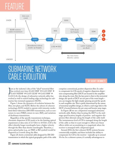
ust as the industry’s idea of the “ideal” terrestrial fiber has evolved over time (G.652 SMF G.653 DSF G.655 NZDSF G.655 LEAF G.652 SMF G.654 LA), the design of submarine network cables has evolved as well to match leading-edge technology for submarine line terminal equipment (SLTE). Figure 1 shows the dynamics of evolution between the fiber, wet plant, and SLTE. Before the advent of coherent technology, SLTE tended to operate with intensity-modulated direct-detection (IM-DD) transmission, such as nonreturn-to-zero (NRZ), return-to-zero (RZ), and variations of duobinary transmission. Regardless of the specific transmission technique, chromatic dispersion (CD) tends to be the limiting optical impairment at data rates of 2.5 Gb/s to 10 Gb/s. CD is the effect whereby longer wavelengths have a higher velocity through the fiber than shorter wavelengths. Therefore, a given optical pulse (e.g., an NRZ or RZ symbol) would be dispersed as it travels along the fiber. Figure 2A shows a terrestrial cable designed for IM-DD transmission in which the typical geographic path of the cable
22
SUBMARINE TELECOMS MAGAZINE
BY GEOFF BENNETT comprises conventional, positive-dispersion fiber. In order to compensate for CD, spools of negative-dispersion dispersion-compensating fiber (DCF) are located in the amplifier sites along the route. But the key point is that in this terrestrial design, the spools of DCF are not part of the route length – you can imagine the light simply spinning around the spools in each amplifier site. This is partly determined by the nature of terrestrial amplifier design, in which a mid-stage link to the DCF is located between the pre-amp and booster amp stages. In Figure 2B we see a dispersion-managed submarine network cable. Rather than locating the DCF in the midstage spool location, lengths of positive- and negative-dispersion fiber alternate along the length of the cable itself. The instantaneous level of CD is managed along the length of the cable so that it is just enough to offset non-linear effects while not accumulating to a magnitude where the receiver is swamped with a dispersed signal. Around 2010, the first coherent SLTE systems became commercially available, and these included the ability to compensate for CD in the receiver – typically up to around 50 s/m. In a coherent system, it’s actually advantageous to
FIGURE 2
have a significant amount of CD in the fiber in order to minimize the non-linear penalty, but coherent SLTE circa 2010 had to use the submarine network cables that were already deployed, and much of this receiver-based CD compensation was effectively wasted. Nevertheless, even this first generation of 100 Gb/s coherent technology with receiver-only signal processing was so superior to 10 Gb/s IM-DD that it delivered roughly a 10-fold increase in fiber capacity. A key aspect of this bandwidth increase is that it can happen relatively quickly – it doesn’t need new cables types to be deployed. The market took almost five years to soak up this first wave of coherent capacity – and only then thanks to the emergence of the hyperscale ICP demand shown in Figure 1. Another key factor in the coherent era is that chromatic dispersion is no longer the enemy – now that it’s possible to electronically compensate for CD, we need to look at the next impairment challenge – non-linear effects. These occur when the optical signal power rises above a certain threshold. There are three common non-linear phenomena: selfphase modulation (SPM), cross-phase modulation (XPM), and four-wave mixing (FWM). By 2014, coherent transponder technology was moving into its second phase, where digital signal processing was performed in both the transmitter and receiver. Among other things, this allows the deployment of uncompensated fibers for both terrestrial and subsea, as shown in Figure 2C. Note that in most terrestrial cables, first-generation coherent technology was able to cope with the accumulated CD even for G.653 SMF. Modern submarine network cables such as SEABRAS-1, MAREA, and AAE-1 are designed with G.654 positive-dispersion fiber that has a large effective area (150 square microns for MAREA compared to around 75 square microns for a typical G.655 LEAF fiber). A larger
effective area and high CD minimize the non-linear penalty and allow higher-order modulations (e.g., 16QAM) to be used. 16QAM carries twice as many bits per second as the previous most common modulation, QPSK, but it is far more vulnerable than QPSK to non-linear effects. The solution to enabling the use of these higher-order modulations over longer distances comes partly through submarine network cable design and partly through advanced transponder technology. Let’s use the MAREA cable as an example, as it currently represents the highest-capacity trans-Atlantic cable in operation.
MAREA CABLE – RECORD-BREAKING TRANS-ATLANTIC CAPACITY
The MAREA cable represents one of the state-of-theart submarine network cables that were designed to make best use of the second wave of coherent transponders – in other words, transponders with both receiver-based and transmitter-based coherent processing. MAREA uses an advanced optical fiber type with a 150 square micron effective area and high chromatic dispersion of around 20 s/m. Both these factors contribute to a low non-linear penalty which, with the right transponder technology, can allow the use of higher-order modulation such as 8QAM or even 16QAM. The amplifier design and spacing in MAREA is also optimized, with a wide, flat gain profile and relatively short spacing of about 55 km. There are eight fiber pairs on MAREA, but the transponder technology used on the record-breaking fiber pair includes a number of technology innovations that boost capacity. These include: • Multi-wavelength transponder based on large-scale photonic integrated circuits (PICs) • Digitally synthesized Nyquist subcarrier transmission SEPTEMBER 2019 | ISSUE 108
23
FEATURE FIGURE 3
• Soft-decision forward error correction (SD-FEC) gain sharing
FIGURE 4
PIC-BASED IMPLEMENTATION
Figure 3 compares an implementation based on six discrete transponders with one based on large-scale PIC technology in which all six waves are integrated onto a single chip. In both implementations, it is essential to lock each wavelength onto its operating value to avoid neighboring channels overlapping and interfering. This is usually done using a wavelength locker (or wavelocker). In a discrete implementation, there is a separate wavelocker on each laser, but they are not coordinated between channels. Inevitably, there is a given level of precision for commercial wavelockers, so neighboring wavelengths must use guard bands to avoid interference, which lowers the spectral efficiency for the fiber. In a PIC implementation, all six waves on the same PIC use a single wavelocker, which means that the shifts in this comb of waves are correlated. If we assume the same level of precision as the discrete wavelockers, guard bands can be eliminated for the waves on the same PIC but are still used between groups of waves on neighboring PICs. The result is significantly enhanced spectral efficiency.
DIGITALLY SYNTHESIZED NYQUIST SUBCARRIERS
Figure 4A shows three potential outputs from an amplitude-/phase-modulated transmitter. On the left is the output from a first-generation coherent system in which there is no transmitter signal processing. Note that the
24
SUBMARINE TELECOMS MAGAZINE
signal has a central peak and symmetrical side lobes. In fact, there are additional higher-order side lobes out to infinity, but only the first-order lobes are considered as the power drops off exponentially. Such a signal is quite wide in frequency, occupying perhaps 50% more than the baud rate (in other words, a 32 GBaud signal may require 48 GHz of spectrum) because of these side lobes. In the center, we see a Nyquist-shaped pulse from a second-generation coherent system in which there is transmitter-based (Tx) digital signal processing (DSP). The Tx DSP digitally shapes the pulse so that it occupies a much smaller amount of spectrum. Note, however, that the shoulders of the pulse are sloped, an effect known as the roll-off factor. Roll-off can be anywhere from around 5% up to 20% of the baud rate. The higher the roll-off, the easier it is to recover the coherent clock from the signal and thus achieve enhanced reach. On the right is a second-generation coherent system in which Nyquist shaping is used to synthesize multiple subcarriers from the output of a single laser. In this case, four subcarriers are created and, for a 32 GBaud carrier, this means that each subcarrier would be transmitted at 8 GBaud.
FIGURE 5
An interesting feature is that the roll-off factor can be different in each subcarrier, which is shown if you look carefully at the subcarrier. This is useful because subcarriers 1, 3, and 4 in this case could be configured with a very low roll-off – between 2% and 6%. Subcarrier 2 has a 20% roll-off, but the clock for all four subcarriers can be recovered from subcarrier 2 because they are all synthesized from the same original carrier. Once again, the end result is enhanced spectral efficiency. Once the signal is launched onto the fiber, a subcarrier signal will tend to experience lower non-linear penalties vs. a single carrier of the same aggregate baud rate because the effective baud rate of the subcarriers lies in the 4 Gbaud to 14 GBaud range – a non-linear sweet spot for all fiber types.
SD-FEC GAIN SHARING
SD-FEC is widely used in coherent transmission, but a traditional approach matches a single FEC processor to a given carrier. Figure 5 shows the situation in which two wavelengths – red and green – are in different parts of the optical spectrum for a dispersion-managed submarine network fiber. The goal in this example is to operate both wavelengths using 16QAM modulation. However, it is quite common in older cables to see a variation in dispersion levels and amplifier across the spectrum. In the conventional SD-FEC approach on the left, the green wavelength is in a region of high dispersion and flat amplifier performance. As a result, the FEC performance for this wavelength is well above the commissioning limit for 16QAM. The red wavelength is not so fortunate. It is located in a region of low dispersion and/or poor amplifier performance, and the FEC performance is below the commissioning limit for
16QAM. In this case, the fiber operator would need to use a lower-efficiency modulation, such as 8QAM, and thus sacrifice 25% of the potential capacity for the red wavelength. Because each FEC is processed independently, there is no way to use the excess FEC gain of the green wavelength to enhance the performance of the red wavelength. By implementing a dual-carrier DSP in which the FEC for both wavelengths (good and bad) can be run through the same processor, the red wavelength can be pulled above the commissioning limit for 16QAM using the extra FEC gain from the green wavelength. Using this technique, dispersion-managed cables can enjoy a doubling of capacity compared to first-generation coherent technology, and up to 25% more capacity than without SD-FEC gain sharing. For MAREA, the end result of optimized cable design and advanced coherent processing in the transponder has delivered a record 24.2 Tb/s of commercial capacity over a single fiber pair on the cable – and there are eight such fiber pairs in MAREA.
WHAT COMES NEXT?
As we have seen from the historical evolution of submarine network systems, this question has to be addressed in two ways – what’s next for transponder design and what’s next for cable design? When it comes to coherent processing algorithms, the designers of transponders know that, for a given generation of DSP, they have a certain number of transistor gates at their disposal. Generally speaking, the more gates, the more effective the coherent algorithms can be. However, techniques like Nyquist subcarriers and SD-FEC gain shar-
FEATURE ing have actually delivered very effective optical performance at a relatively low cost in DSP power. In addition, each generation of DSP technology tends to move to a smaller node size, and we’ve seen this pass from 40 nm to 28 nm to 16 nm (the current commercially available node size) and soon 7 nm (commercial transponders in 2020), followed by 5 nm (commercial transponders in 2022). Existing features, such as SDFEC, Nyquist subcarriers, clock recovery techniques, and non-linear compensation, can all be enhanced as additional DSP power becomes available. In addition, it may now be possible to implement new features thanks to the additional processing power. Let us consider one example of each – an enhanced existing feature and a new feature.
FIGURE 6
FIGURE 7
ENHANCED NYQUIST SUBCARRIERS
Subcarriers have been an unexpected success in coherent transmission, delivering somewhat more benefits in both submarine network and terrestrial transmission than was originally expected. As experience grows with this technology, it is clear that there is more benefit to extract. Figure 6 shows a next-generation 800 Gb/s transponder operating at 96 GBaud for the carrier, which is divided into eight 12 GBaud subcarriers. One might expect the data payload to be evenly distributed across all eight subcarriers, as shown on the left of Figure 6. While this is possible, we know that optical impairments tend to act most strongly on the outer subcarriers, so the reach of this carrier is limited by the performance of the outer subcarriers. On the right we see an alternative approach in which the payload is reallocated so that the outer subcarriers are less loaded and the inner subcarriers are more heavily loaded. Overall, the carrier is still operating at 800 Gb/s, but it will have an improved reach compared to subcarriers with equally allocated payloads.
PROBABILISTIC CONSTELLATION SHAPING (PCS)
High-order modulation is the key to delivering enhanced spectral efficiency and increasing fiber capacity.
26
SUBMARINE TELECOMS MAGAZINE
However, optical reach drops off exponentially as bits per symbol increases, and this can limit the applicability for the highest-order modulations such as PM-64QAM and PM-32QAM. Figure 7 shows, for example, that 64QAM delivers very high fiber capacity, but at extremely short reach, whereas BPSK can close incredibly long fiber links, but with far less capacity. This is a matter of physics, and the gray dotted line shows the theoretical limit – the socalled Shannon limit – for an optical fiber. One part of this problem is that switching between discrete modulation techniques like BPSK and QPSK creates a “sawtooth” in the capacity-reach curve, effectively dropping the capacity further away from the Shannon limit at certain distances. PCS recognizes the fact that in, for example, a 64QAM constellation, the outer symbol locations are more difficult for the receiver to detect reliably. So, a PCS implementation will map the incoming data stream preferentially to the inner symbol locations, thus increasing the reach – but more importantly, it can do this in a smooth gradation and avoid the hard sawtooth curve. A second feature of PCS is that, with sufficient processing power such as that delivered by 7 nm
ASIC technology, PCS can provide a form of error correction that moves the entire capacity-reach curve closer to the Shannon limit. One aspect of this latter capability is the need to be able to map the data stream for transmission into the reduced range (and probability) of constellation locations in PCS. If a given PCS implementation is able to look further into the data stream, it can perform this mapping far more effectively. This is known as the codeword length, and it is similar in principle to the idea of a chess program that is able to look a certain number of moves ahead – the more moves ahead the better the program will play. A basic PCS may look at around 100 symbols of data, while an enhanced PCS will look around 1,024 symbols ahead. Larger codeword sizes are possible, but they result in a rapidly diminishing return on signal quality. Using second-generation Nyquist subcarriers and PCS, what level of increased capacity can we expect using a MAREA-style submarine network cable and a next-generation transponder? Initial modelling shows between a 25% and 50% increase – which is pushing these fibers very close to the Shannon limit.
NEXT-GENERATION SUBMARINE NETWORK CABLES
If coherent technology is pushing against the Shannon limit in state-of-the-art submarine network cables, the only option for more capacity is to create more bandwidth in the fiber or in the cable. But what does that mean in practice? Consider the MAREA cable as an example. Very large effective area fiber is used with very narrow amplifier spacing, and the amplifiers themselves operate at high power levels. Note that, like almost all submarine network cables, MAREA operates in the C-band only (the range of wavelengths from about 1530 to 1565 nm). MAREA has eight fiber pairs, and this number is limited by the need to electrically power the amp chain in the cable. This is done by using massive voltages – +15,000 volts at one end of the cable and -15,000 volts at the other. Increasing the voltage may not be an option as it may result in an increased risk of electrical shorts over the life of the cable. One option would be to implement both C-band and L-band (1565 to 1625 nm) amplifiers along the cable. The L-band contains at least as much bandwidth as the C-band, so the capacity of the fiber pair would be doubled. However, L-band amps use at least as much power as C-band amps, and a C+L equivalent of MAREA would, therefore, only be able to support four fiber pairs before the electrical power limit was reached. So, a C+L MAREA-style cable would have no more capacity in the cable overall, but there would be a savings in terms of the total amount of fiber used
compared to C-band only. It is not clear if this would be a good trade-off, especially when the primary objective is to increase total cable capacity. For this reason, only one C+L cable has been deployed at present, and it is likely to be the last such cable unless circumstances change in favor of C+L. Note that C+L is already taking off in terrestrial cables, where the options for powering the amplifier chain are totally different. Another approach to next-generation submarine network cable designs has been dubbed “spatial-division multiplexing,” or SDM. Like any technology, SDM will evolve in phases, but the initial objective is to enable additional fiber pairs to be supported in the cable by using electrical power-saving techniques such as: Sharing of backup amplifier pumps (“pump farms”) Increased amplifier spacing Reduced amplifier power levels In addition, it is expected that SDM would involve a return to smaller effective area fiber, which has less critical bending sensitivities and would thus allow more fiber pairs to be packed into the existing cable design. Future evolutions of SDM include the idea of moving from a copper electrical layer in the cable to one made from aluminum. Aluminum is a less expensive conductor, but the primary reason it is interesting is that there would be less of a voltage drop along the cable compared with copper, which would allow for an increase in the number of fiber pairs supported. The first phase of SDM would enable the doubling of fiber pairs in a trans-Atlantic cable from eight to sixteen. Next-generation coherent transponders with highly efficient PCS are expected to deliver in the region of 20 Tb/s per fiber pair, compared to a MAREA-style cable in which we can expect 30-35 Tb/s using next-generation transponders. The total cable capacity would increase from 280 Tb/s to 320 Tb/s. But 16 fiber pairs is only the first step. Plans are already under discussion to move to 25 fiber pairs, and even to 32 to 50 fiber pair systems in the future. Using technologies we can already build today or in the near future, a 1 petabit trans-Atlantic submarine network cable is certainly possible. STF GEOFF BENNETT is the Director of Solutions & Technology for Infinera, a leading manufacturer of Intelligent Transport Network solutions. He has over 25 years of experience in the data communications industry, including IP routing with Proteon and Wellfleet; ATM and MPLS experience with FORE Systems; and optical transmission and switching experience with Marconi, where he held the position of Distinguished Engineer in the CTO Office. Geoff is a frequent conference speaker and is the author of “Designing TCP/IP Internetworks”, published by VNR.
SEPTEMBER 2019 | ISSUE 108
27
BACK REFLECTION
BY JOSÉ CHESNOY
RISE ABOVE
STF-INC 28
SUBMARINE TELECOMS MAGAZINE
ELEVATE YOUR COMPANY. ADVERTISE IN SUBTEL FORUM SubTel Forum publications are read and used by decision makers across the entire submarine cable industry.
NC.COM SEPTEMBER 2019 | ISSUE 108
29
FEATURE
BY GREG BERLOCHER
TECHNOLOGY DRIVERS IN THE ENERGY INDUSTRY: Connected Workers, Cloud Computing, Internet Of Things, Rig Automation and 4D Seismic
T
echnology plays a huge role in the search for and production of hydrocarbons, but the adoption of cutting-edge technologies in the Energy Industry will yield even further improvements in Exploration, Production, Worker Productivity, and Safety. When the Internet was new in the 1990s, the general public had no idea of the tremendous impact it would have on their daily lives, including: work environment, business tools, how they would communicate, personal entertainment, shopping and social interaction. On a similar note, a handful of disruptive technologies will have same potential to create major paradigm shifts in the Oil & Gas Market, ultimately driving future demand for bandwidth around the globe. The technologies include: Blockchain, Connected Worker, Internet of Things (IoT), Cloud Computing, Rig Automation, and 4D Seismic. The Energy Market is multifaceted and is generally broken into three major segments: Upstream, Midstream, and Downstream. For simplicity sake, if you think of an oil
30
SUBMARINE TELECOMS MAGAZINE
refinery as midpoint, the terms upstream and downstream are easier to conceptualize. The upstream market segment includes all the activities that happen before oil reaches a refinery. This includes exploration, drilling, and production. Midstream is a relatively new term that replaced Refining as the middle segment of the Oil & Gas Market because it is more inclusive. The Midstream Market Segment includes gathering pipelines, refineries, and natural gas plants, as well as a transportation options, such as pipeline, rail, ships or barges, or trucks, for moving crude, refined products and natural gas to downstream distributors. The Midstream Market Segment also includes storage and wholesale marketing. The Downstream Market Segment includes the marketing and distribution of products derived from the processing of natural gas or the refining of crude oil. Transportation and Retail are large segments in the Downstream Market. Let’s examine some of the hottest technology trends and how they will drive the demand for global bandwidth:
BLOCKCHAIN
Blockchain is best known as the underlying technology for crypto currencies but it is an emerging technology that is being used in the Energy Industry. The secret to blockchain is a distributed ledger than can be duplicated but not edited. Every time a new transaction is made, the ledger is updated and then distributed. Multiple parties receive and distribute the same blockchain ledgers. Since the data in the ledger can’t be edited, the ledger provides a reliable audit trail that can used by all parties as a perfect record, and since there are multiple copies of the ledger, it is inherently safer than data stored in a central repository. There have been multiple applications proposed for blockchain technology within the Energy Industry. “A blockchain implementation provides a platform for multiple parties to transact with one another, without the need for third party validation, creating a ledger of records that is by design more secure and trusted than other approaches,” explained Ansar Nubeel in his article in Digital List. One practical application for blockchain is the payment of oil & gas royalties. Invariably, there are always disputes in the monies paid in a royalty transaction and it can often take many months to resolve these issues. In this particular application there are three parties: a producer, a landowner and a royalty holder. A blockchain platform would allow these disparate interests to reach consensus on the calculation and settlement of royalties by sharing key information via a distributed ledger. Real time settlements could be executed quickly, shortening the overall process, but also dramatically reducing settlement costs.
CONNECTED WORKER-LONE WORKER
The pursuit and production of hydrocarbons is fraught with challenges, some of which can be extremely dangerous. Oil and gas wells are routinely drilled in harsh locations, like jungles, desserts, in mountain ranges, and in inhospitable bodies of water, like the North Sea. Energy companies are under constant pressure not only to improve efficiencies, reduce costs, and improve profits, but they are striving constantly to improve safety. If a company is known to be lax on safety, it can adversely affect the outcome of injury lawsuits, but other companies will begin to shy away from doing business with them. In days past, safety slogans like “Safety first!” were greeted with a wink and a nod. Today’s energy companies no longer feign concern over safety, but take an active role ensuring that safety policies are fully un-
derstood and enforced. Health, Safety & Environment (HSE) organizations now play significant roles in the management of global energy companies. Not too many years ago, communication with mobile workers was limited. People in the field typically communicated over a radio link via a dispatcher. As the Cellular Market matured, smartphones began to appear and were ultimately adopted by the masses. In parallel, mobile broadband services matured, along with location-based services and data apps. These advances in mobile communications were the DNA of today’s connected worker programs. Connected workforce applications allow energy companies to eliminate manual processes and ensure regulatory compliance by eliminating paper-based systems, which are prone to error, and replace them with applications that help employees complete their tasks correctly and safely. Connected workforce applications improve efficiency and accuracy of data that is collected from the field. These programs also improve safety processes by streamlining data collection processes. Connected workforce applications can also help bridge the skills gap in employees. Remote workers are hard to track, and they often work by themselves. Connected worker and lone worker programs are initiatives that allow workers to request help in the event of an accident. The latest trend in connected workforce applications is wearable technology. Employee tracking is the first tangible benefit. Should a major event happen inside a refinery or gas plant, such as a fire or explosion, having a time-stamped location of every employee is invaluable and much more reliable that a human doing a manual head count at a muster station. Wearable devices that incorporate microphones allow for the collection of auditory information, such as the sound signature of failing mechanical equipment or a highpitched squeal of a leaking pipe that is above the frequency range of the human ear. Video cameras allow for remote expert support and collaboration between the remote worker and subject matter expert located at a central location.
CLOUD COMPUTING
Over the last decade, cloud computing has become a mainstream service and this paradigm shift has had enormous impacts, not only on IT organizations within energy companies, but also on bandwidth demand. Rather than own and operate racks of servers and software, companies
FEATURE and organizations now contract for computing services as if it were electricity provided by a utility. The strategic benefits of cloud computing are huge: 1) elasticity, allowing companies to pay for only what they consume; 2) virtually unlimited computing power when needed; 3) broadband access from practically anywhere from a wide variety of devices, such as laptops, smart phones, and tablets; 4) global access to the cloud; and 5) increased network security. The Gartner Group forecasts that the Public Cloud Services Market will grow 17.3 percent in 2019 to a total of $206.2 Billion, up from $175.8 Billion spent in 2018 (Source: Gartner). As the demand for cloud computing grows, there is a parallel demand for bandwidth. To successfully migrate from a private server architecture to a cloud-based solution, companies must beef up their wide area networks (WAN) to support the interaction of users with software applications that now reside in the cloud. Not only must fat pipes be ordered and installed, wide area networks must be engineered to maximize uptime. Backup circuits, alternate ingress and egress into buildings and facilities, and backup networking gear must be factored in a sound cloud strategy. IT organizations aren’t the only ones that must beef up their architectures. Large internet companies, such as Google, Amazon, Facebook, and Microsoft, are all building data centers around the world. Their goal is to put data centers as close to their consumers as possible, where they can store video content locally. A shorter data connection minimizes latency and provide end users the best possible user experience when they download content. But as the number of private data centers grow, they must be synchronized. According to Geoff Bennett, Director of Solutions & Technology at Infinera, the large Internet companies will consume more bandwidth synchronizing their private data centers than is consumed by public Internet traffic. Think about that for a second. This has led to several private fiber initiatives, such as the Microsoft-Facebook-Telxius subsea fiber between North Caroline and Spain. In addition, Google has invested in numerous subsea cables, providing them exclusive access, along with their investors, to needed bandwidth in certain regions. So, as you can see, as the Cloud Computing Market grows, the demand for bandwidth will continue to increase.
32 SUBMARINE TELECOMS MAGAZINE
INTERNET OF THINGS (IOT)
The Internet of Things (IoT) has become mainstream and IoT applications are being adopted by every facet of the Energy Industry, providing gains in efficiencies, and enabling big data analytics to be performed, often for the first time, on equipment in the field. The Internet of Things (IoT) is an outgrowth of SCADA (Supervisor Control and Data Acquisition) systems which have been used for over 50 years to control pipelines, electric utilities, and water/wastewater systems. In the early 1990s, lightweight SCADA services began appearing, with the market segment known as Machine-to-Machine (M2M). These early services often focused on the delivery of a single service, such as measuring the fluid level in a tank. Kevin Ashton, founder of MIT’s Auto ID Lab first used the term Internet of Things (IoT) in a presentation in 1999 and IoT became fashionable. IoT is an all-encompassing term that includes a wide range of industries, technologies, and service offerings. It should be noted that distinctions can be made between IoT services aimed at consumers and services aimed at energy companies, and other industrial users. Manufacturers of everything from refrigerators to air conditioners can be connected to the Internet. Google paid over $1 Billion to acquire Nest, the manufacturer of Internet-enabled thermostats. From a bandwidth perspective, it should be noted that the consumer market for IoT services is different than the market for Industrial Internet of Things (IIoT). Consumer IoT services generally piggyback on existing Internet connections, like the one in your home. As such, consumer oriented IoT services in developed countries don’t drive much demand for new bandwidth. IIoT applications, on the other hand, which are used to monitor and control industrial assets, typically require new Internet connections, hence driving new demand for bandwidth. Traditional SCADA applications are very low bandwidth connections, so one may question how much bandwidth IIoT connections will drive? It is interesting to note that audio, video, and data are now being integrated into IIoT applications, creating a much larger demand for bandwidth. In the past, video would never have been considered in SCADA applications due to costs but with the advancements of IP-based cameras with integrated analytics, video is now a robust part of many IIoT applications.
PRE-ORDER NOW 25% OFF
INDUSTRY LEADING ANALYSIS FROM THE VOICE OF THE INDUSTRY Submarine Telecoms Market Sector Report: Data Center & OTT Provider Edition
Featuring exclusive data and analysis from STF Analytics – • Exclusive data and insights from industry experts • State of the market and changing trends • Impact on cable system development • Signature Analysis • Priced for every budget
BUY YOURS TODAY!
STFANALYTICS.COM/DATA-CENTER-OTT-REPORT SEPTEMBER 2019 | ISSUE 108 33
FEATURE RIG AUTOMATION
Drilling rigs are amazing marvels of engineering capable of drilling vertical and horizontal holes into the Earth’s surface that are many miles in length. Drilling rigs, drill bits, drill pipe, crews, and support services are all secured on short term contracts, typically a daily rental. The day rate for a land rig ranges between $8,000 - $40,000 per day, depending on the rig size and region. Day rates for offshore rigs average 15 -20 times higher, with the largest offshore rigs equipped to drill in deep water renting for $250,000 $400,000 per day. Day rates include the drilling crew but don’t include additional contractors, or support vessels that may be needed. It is common for loaded costs of a deep water rig to range from $750,000 - $1,000,000 per day. There are serious savings if an oil company can shave a few days off the time it takes to complete a well. Robotics and rig automation have greatly increased the safety and efficiency of drilling operations, as well as driving operational costs down. Robotic tools now assemble and disassemble pipe joints, a dangerous task done previously by rig hands wielding large hydraulic tongs. Rig manufacturers have automated as much of the surface operations as possible, creating a “manless drilling floor”. The development of automated drilling systems gets people out of harm’s way and dramatically increases operational safety. Drilling companies have been developing expert systems over the last decade to further improve efficiencies. In addition to capturing and cataloging best drilling practices from retiring drillers, broadband networks have been deployed to allow the interaction of the driller onboard a rig with a centralized control center in Houston. A drilling manager in Houston can oversee four or five individual drillers, proving oversight and expertise when needed. These collaborative systems continue to improve, thereby increasing the hunger for bandwidth.
4D SEISMIC
4D seismic, or time lapsed seismic, is an improved method of modeling oil and gas in a reservoir. Seismic data is gathered using a series of hydrophones embedded in the earth’s surface to gather sonic waves that are reflected off different strata below. When the seismic data is processed, a 3D image is created allowing geophysicists to map the subsurface of the earth, showing the stratification of an underground reservoir and its contents.
34
SUBMARINE TELECOMS MAGAZINE
After a well has been stimulated in order to increase production, a production engineer will order a seismic survey to look at the geologic structures around the well(s) and the movement of oil to see if the stimulation was successful. In offshore applications, large ships tow large arrays of hydrophones and capture the reflected sound waves bounced off the oil formation. Due to the cost and time delays of securing the services of a seismic vessel, seismic surveys are done only when economically justified. Instead of towing the hydrophones behind a ship, which provides the production engineer a snapshot in time, 4D seismic systems utilize a network of hydrophones that are permanently embedded in the seafloor and connected by fiber optic cables. Since the seismic array is permanently installed, it can gather data on an ongoing basis, providing valuable and historic data that the engineering can use to increase production. The raw seismic data from the 4D hydrophones would be connected via a subsea fiber optic cable run back to the beach or to a branching unit of an existing subsea cable system. 4D Seismic systems provide continuous feedback on the status of a well, rather than snapshots in time. It is estimated by geophysicists that this near real-time data could increase yields as much as 8% over the well’s lifetime. As this technology gains widespread adoption on deep-water wells, look for an ever-increasing network of subsea fiber optic cables crisscrossing the world’s offshore oil basins.
CONCLUSION
The Energy Market has been an early adopter of information technology, including mainframes, supercomputers, workstations, cloud computing, global WANs, and dark fiber. Look for exciting new trends in the Energy Industry to continue the demand for more bandwidth in the future. STF GREG BERLOCHER is a veteran of the Telecommunication Industry and has spent 40-years building advanced telecommunication networks for the Oil & Gas Industry. Mr. Berlocher is also an award-winning author and writer, having published 350+ magazine articles and 2 books. Over his career, he has worked for three INC 500 companies and one Branham 300 company. Mr. Berlocher is the CEO of New Star Energy Services, which specializes in providing telecommunication solutions to facilities in remote locations and in harsh environments.
STAY CURRENT FOLLOW US ON SOCIAL MEDIA
SUBTEL-FORUM
@SUBTELFORUM
@SUBTELFORUM
SUBTELFORUM
FEATURE
36
POWERFUL ANALYTICS
SUBMARINE TELECOMS MAGAZINE
CUSTOMIZED REPORTING Delivered in 10 business days SPECIAL MARKETS — Oils & Gas, Cableships, Upgrades and more From REGIONAL TO GLOBAL Market Reports
ORDER YOURS TODAY
STF ANALYTICS CUSTOM REPORTING
WWW.STFANALYTICS.COM
SEPTEMBER 2019 | ISSUE 108
37
FEATURE
THE 2019 US OFFSHORE WIND MARKET UPDATE:
Submarine Power Cable Installation, A Delicate Balance
I
ts 2016 and the culmination of nearly 10 years development is reaching fulfillment as the Block Island Offshore Wind Farm (BIWF) comes online in Rhode Island. Five 6MW GE Turbines, sitting atop traditional 4-leg jacket foundations, 2.9 miles off the south-east corner of Block Island, generating 30MW of renewable energy to serve the community of Block Island. The surplus power generated being transmitted to the Rhode Island mainland via the Block Island Transmission System (BITS) a newly installed 31KM submarine power cable connecting Block Island to Narragansett on the RI mainland. Kudos to Deepwater Wind of Providence RI the developer of the Block Island Wind Farm, offshore wind had arrived in the US.
2019 UPDATE
Fast forward to August 2019 and the US Offshore Wind market has suddenly grown very large, very quickly. Deepwater Wind is now part of Orsted the large Danish Offshore Wind developer now with a US HQ in Boston MA. (Orsted purchased Deepwater Wind in 2018 for $510M). Along with Orsted a plethora of offshore
38 SUBMARINE TELECOMS MAGAZINE
BY BILL WALL
wind developers are vying for the rights to develop projects off the US North East coast. These include Shell New Energies, EDPR, EDF, Equinor, Avangrid, CIP, ENBW, US Wind and others. The current wind energy lease areas that have been acquired by developers in the US northeast region is shown to the right. There is now approximately 4,800MW of Offshore Wind energy planned by US developers in the North East region with “Offtake” agreements. An offtake agreement is either a Power Purchase Agreement (PPA) or an Offshore Renewable Energy Credit (OREC) whereby a developer has a contract with either a state agency, a public utility or a group of utilities to purchase the power from their proposed offshore wind farm, usually in response to a state issued RFP for renewable energy. These offtake agreements enable the developer to attract project finance and get to the stage whereby the developer can begin solid orders with Tier One Block Island, America’s First suppliers and plan construction Offshore Wind Farm schedules. As shown below the projects with offtake agreements
renewables to tap into a massive renewable energy source sitting right off of their load centers and allowing them to meet their individual clean energy goals. (Often referred to as a state’s Renewable Portfolio Standard or RPS). Second is the economic benefits that will ensue, the developer of a utility scale (400MW to 1200MW range) will generate hundreds of millions of dollars of economic activity in a state plus they will also create thousands of local jobs across both the construction phase and the O&M phase (25 years+). The states view this as a win-win situation. Organized labor also supports the projects; the jobs created cover the whole gamut of trade disciplines such as electrical, marine trades, pile drivers, divers, dock builders, operating engineers, laborers etc.
SEABED HARMONY: WELCOME TO THE NEIGHBORHOOD!
The Northeast offshore region of the US and in particular the area known as the New York Bight between the New jersey Shore line and the southern shore of Long Island NY is home to a multitude are all aiming for a of existing ocean and Commercial Operation seabed users. The main Date (COD) in the inbound and outbound 2023/2024 timeframe. shipping channels into This “Rush to Market” and out of the busy may put a strain on the New York/New Jersey available supply chain port complex traverse so developers are acthe area, plus the tively seeking support in-shore Tug/Barge from local suppliers routes ply Northacross all disciplines. South routes. These Individual projroutes are controlled ect names include by the USCG from Empire Wind, Maytheir Sector New York flower Wind, AtlanVessel Traffic Centic Shores Offshore Current Northeast Region Lease Areas Acquired by OSW Developers - BOEM ter on Staten Island, Wind, Vineyard Wind, New York. Natural Boardwalk Wind, gas pipelines cross Ocean Wind, Revobetween New Jersey and New York, an HVDC submarine lution Wind, Sunrise Wind and others. Individual states along the East Coast have issued mandates for the purchase power cable interconnector crosses from the Jersey side over to Long Island, numerous shore side communities have of offshore wind energy, these include New Jersey with a municipal outfalls extending into the ocean. A myriad of call for 3500MW, Connecticut 2000MW, Massachusetts 1600MW, Rhode Island 400MW, Maryland 1200MW and fishing activities is conducted out of the many fishing ports along the New Jersey and New York coastline. These inNew York State with a massive target of 9000MW. The clude clam dredging, trawling, scallop dredging, long-lining North Eastern states regard offshore as a two-fold advanetc. As SubtelForum’s regular readers know the area is also tage; First it allows states with little or no land ashore for SEPTEMBER 2019 | ISSUE 108
39
FEATURE home to multiple in-service Trans-Oceanic telecom submarine cables along with numerous out-of-service cables. The latest SubTel Forum “Submarine Cables of the World” map portrays the current situation of active telecom systems in the region. The offshore wind developers will have a busy time interfacing and coordinating with the various ocean/seabed users, port operators, USCG and utility owners. Crossing agreements, cable locating surveys and crossing configurations may be the order of the day!
SUBMARINE POWER CABLES, PERMITS AND THE DELICATE BALANCE
Project COD Targets – Courtesy of Power Advisory Inc. of Boston, Massachusetts
Submarine power cables play a major role in offshore wind farm development. In a utility scale wind farm the cables play 2 roles. Firstly, they are used to interconnect the offshore turbine strings in a “Daisy Chain” fashion and then connect the end of each string to the offshore sub-station. These are known as the Inter Array Cables (IAC) and operate at medium voltage levels of either 34.5KV or 66KV. (66KV is more prevalent recently). From the offshore sub-station, the Export submarine power cable carries the power to shore this time at a high voltage level. In the Northeast region, depending on the interconnection site ashore, the export cables will most likely be operated at either 138KV, 230KV or 275KV. The submarine power cables in use are 3-core design with an embedded fiber bundle for SCADA operations. Typical design parameters for 3-core cables are shown to the right. The typical IAC weight and dimensions will be in the range of 30KG/M to 50KG/M in air with an outer diameter between 150mm to 170mm. The typical Export cable weight and dimensions could be in the range of 90KG/M to Submarine Telecom Cables in the NY Bight – Courtesy of SubTel Forum 140KG/M in air with an outer diameter between 230mm and 260mm. Some of the longer export cable routes of 80 to 90KM will mean a total cable of Offshore Energy Management (BOEM). BOEM is part load weight in the region of 10,000MT. of the US Department of Interior and controls all land in As with all offshore construction in order to install the the Outer Continental Shelf (OCS) seaward of the states submarine power cables regulatory permits must be applied 3-mile limit out to the 200-mile limit of the Exclusive for and obtained. In the US offshore wind sector, the fedEconomic Zone (EEZ). Each of the states in the Northeast eral agency governing OSW in federal waters is the Bureau region has jurisdiction from the coastline out for 3 miles
40 SUBMARINE TELECOMS MAGAZINE
and each state has an agency overseeing the environmental aspects of work in that state’s waters. New York has the Department of Environmental Conservation (NYDEC) New Jersey Department of Environmental Protection (NJDEP) and so on.
SUBMARINE POWER CABLE SHORE LANDINGS
When drilling thru certain strata there is a possibility that the drilling lubricant will escape thru a fracture in the strata instead of returning to the entry point as designed. This occurrence is known as an “Inadvertent Return” or IR and the regulator will usually stipulate that the installation team has an IR contingency plan to find and stop the leaking fluid and to then recover any Bentonite that was inadvertently spilled onto the seabed. The IR contingency plan will usually be one of the major stipulations required when the final permit allowing construction is issued.
Most, if not all, of the state regulators will require the export cable landings on shore to be connected through a conduit installed via a Horizontal Directional Drilling (HDD) process. Open Cut techniques are considered environmentally damaging to beach dunes and other sensitive coastline areas and have not been used for SUBMARINE POWER CABLE some years now. In most coastal BURIAL communities there are “Time of Another stipulation that Year” restrictions as to when HDD usually both state and federal construction is allowed to take place. permit regulators require is HDD operations will usually only cable burial. This is also usually Typical 3-Core Submarine Power Cable Design Parameters be allowed in the fall/winter period, included in the developer’s sysOctober thru March is a likely scetem design to protect against nario. A typical drill rig for Submaexternal aggression. Historrine Power cable HDD operations is shown here. ically on the US east coast power cable burial has been Although considered less environmentally damaging stipulated in regulatory permits at a 6’ target depth with a there are processes within the HDD construction method 4’ minimum. There are many different methodologies for that regulators view with caution and place stipulations cable burial and the seabed composition found during the upon certain operations. The HDD methodology for Marine Route Survey will dictate which methodology is submarine power cable chosen. For this discussion installation consists of we shall review the typical three main operations: 1. methodology that will Drilling a pilot hole, 2. probably suit burial in the Reaming the pilot hole out NY Bight region and that to a larger diameter and 3. is burial via a water jetting Pulling in a High-Density system. Traditionally on Polyurethane (HDPE) the US East Coast power conduit into the reamed cable has been installed hole. The pilot hole drill via a simultaneous lay and and the reaming process burial procedure using a utilize a Bentonite slurry Jet Plow for burial. In Euas a drill lubricant. This rope it has been somewhat lubricant is pumped from more prevalent to employ the drill entry location a Post Lay Burial Opera“down-hole” and retion (PLBO) methodolturned to the drill entry ogy whereby the cable is location in a continuous surface laid, and burial is Typical HDD Drill Rig for Submarine Power Cable closed-loop circulation. completed post lay from a SEPTEMBER 2019 | ISSUE 108
41
FEATURE second vessel with a Remotely Operated Vehicle equipped with a jetting tool. The two different tools are shown on the next page: Both methods employ a jetting technique whereby the seabed is liquefied by injecting high-volume, medium pressure water jets and the cable is guided into the resultant trench. The Jet Plow method is more suited to shallow water operations as the water supply is fed from the surface vessel whereas the ROV utilizes an on-board pump system for water supply. In these two methodologies the permit regulators are most interested in the turbidity caused by each tool and the resultant effect on water quality. A stipulation on the final permit will usually be imposed whereby the operation of the tool(s) must be within a defined turbidity parameter. The measurement of turbidity is either in Total Suspended Solids (TSS) usually measured in parts per volume/milligrams per liter, or a turbidity measurement in Nephelometric Turbidity Units or NTU. The stipulation will basically limit the amount of TSS or the value of NTU’s that are generated during burial operations before the installer must take action to lower the turbidity generated.
Surface Lay and PLBO
SUMMARY
Offshore Wind is destined to grow at an accelerated pace in the US. A recent report by the US Department of Energy indicated that there is a potential generating capacity of over 25,000MW for offshore wind in the US. (This report from NREL can be accessed at the following link https://www.energy.gov/eere/wind/downloads/2018-offshore-wind-market-report). This will mean many more utility scale projects being built and many more permit negotiations between developers and the regulatory agencies. All parties involved in these processes the agencies, the developers, contractors, manufacturers, stakeholders etc are all striving to achieve minimum impact to the environment. This is definitely a Delicate Balance and it is often worth a temporary disturbance to achieve a permanent advantage. This article has concentrated on the US north east coast region as that is where the current offshore wind industry cycle is centered. The northeast coast has a benign, gently sloping shelf which lends itself readily to bottom mounted foundations such as jackets, monopiles etc. It should be noted that on the US west coast which has a short and abrupt shelf leading to much deeper waters there are many plans and proposals for offshore wind farms utilizing floating foundations. This market will likely be the site for the next big expansion of offshore wind energy in the US. STF
42 SUBMARINE TELECOMS MAGAZINE
Simultaneous Lay and Jet Plow Burial
BILL WALL has over 40 years of worldwide offshore marine construction and development experience specializing in submarine cables and offshore wind projects. He has held positions ranging from sales, marketing, project management, contract negotiation, project development and project implementation in the marine industry for various companies including his previous positions at offshore wind developer Deepwater Wind, offshore transmission developer The Atlantic Wind Connection and US Wind Inc. in Maryland. He is currently the Project Director at LS Cable America Inc. in Fort Lee NJ. LS Cable America is a leading supplier of submarine power cable systems to the Offshore Wind Industry. During his tenure at Deepwater Wind (2007-2011) he worked on the initial development of the Block Island Wind Farm. Upon joining LS Cable America in 2015 he became project director for the Block Island and BITS submarine cable supply and installation project which LS had been awarded earlier in 2015. It was nice to come full circle on a project.
SEPTEMBER 2019 | ISSUE 108
43
FEATURE
DIGITALIZATION IN THE OFFSHORE INDUSTRY The use of passive cables enables flexible, dynamic and long-life subsea optical fibre networks. Why is that so?
BY STEINAR BJØRNSTAD
D
igitalization is gaining importance and featuring higher up on the priority list for the offshore energy industries, Oil & Gas and Windfarms now growing rapidly. Collectively driven by a need for greater efficiency and faster decision-making, remote control of manned oil-platforms from onshore is already a reality.
REAL-TIME DECISION-MAKING
The Ivar Aasen platforms in the North Sea already have their production and equipment monitored from Trondheim by owners Aker BP who announced earlier this year that they had become the first company on the Norwegian Continental Shelf to operate a staffed platform from an onshore control room. In addition to monitoring facilities, production, equipment, and following up everything that takes place on the field, the control room plays an important role in activating work permits and for the arrival of vessels and helicopters within the 500-meter zone. Also, because digitalization reduces the need for transport of workers, it contributes to reducing the CO2 footprint of the oil and gas industry. In the company statements relating to this innovate step Aker BP announced that “considerable potential for increased revenues because the subsurface experts are closer to the control room, which can give better mutual understanding and common goals”. This article explores how this aim can be realized over existing infrastructure using optical networks based on passive fibre optic subsea cables combined with advanced optical network elements located on offshore installations.
44
SUBMARINE TELECOMS MAGAZINE
THE DIGITAL OIL WORKER
While Internet of Things (IoT) sensors and devices are already established onshore and in other industries, it is still in the nascent phase offshore. However, more and more devices for offshore communication, monitoring and control purposes are now available and widely used in all areas of these businesses from Human Capital Management where the digital oil-worker is equipped with devices like cameras, sensors woven into clothing and communication equipment to Advanced Analytics for greater production efficiencies. In parallel with this, stable wireless communication plays a key role in the delivery of this strategy. In addition to their existing fibre infrastructure Tampnet started building offshore mobile LTE networks approximately eight years ago and is now covering large parts of The North Sea and Gulf of Mexico and allowing vessels in these regions benefit from marine coverage at high capacities through the mobile network. The LTE coverage includes both outside areas and large part of indoor areas on structures, enabling digital workers seamless communications while at work and allowing for an improved living experience during personal time with previously unimaginable access to the same online media taken for granted on dry land.
LOW-LATENCY BACKHAUL NETWORK – THE KEY ENABLER FOR FUTURE SERVICES
For realizing a highly available mobile network, a high capacity backhaul network with redundancy is key. Tamp-
net was established in 2001 and owns and operates a subsea fibre network combined with a network of microwave links and offshore LTE network. In addition to serving wireless communications, services supported include latency critical activities like video conferencing, supervision of drilling operations and Remote Operated Vehicle (ROVs) control. The Tampnet network has been designed to deliver services with low latency, high capacities and service availability, features essential for a successful digitization roll out and not achievable over existing alternatives such as VSAT connectivity. The delay in a fibre network corresponds to 5 microseconds/km. Hence even for distances of e.g. 1000 km, delay will be lower than 5 ms. Latency of satellite networks relying on geostationary orbits (like e.g. VSAT) is approximately 500 ms, too high for ROV control or satisfactory videoconferencing and voice communication. 5G will be a driver for future digitalization and emerging services will continue to demand low latency. In essence, the fibre network is not only supporting current low-latency services with enhanced efficiencies but is also opening up for future implementation of advanced interactive services like Augmented Reality (AR) and Virtual Reality (VR), that may tolerate only a very few milliseconds of delay. While Low Earth Orbit (LEO) satellites are in time expected to increase the availability of high capacity services and lower the latency in satellite services, latency will still be close to 30 ms, i.e. too high for supporting AR/ VR services. Furthermore, given the increased data flow from connected oil fields, it is crucial that fibre optic cables can deliver Terabits of capacity per fibre pair with the added benefit of dedicated and isolated capacity for each user and service addressing another key factor of security and availability of the network.
FUTURE PROOF COST-EFFICIENT FIBRE TRANSPORT USING PASSIVE CABLES
While operational improvements are the main driver to any offshore digital strategy, cost efficient deployment of the underpinning subsea network becomes increasingly important. Previously in Submarine Telecoms Forum Magazine, the cost-efficiency of using passive fibre cables versus active fibre cables has been discussed. For the longest span distances, 1000 km and more, capacity may become too low for practical purposes and not cost-efficient, however, for offshore communication to oil-platforms in the north-sea distances are typically less than 300 km. Using passive fibre cables in combination with Raman optical amplification techniques has then proven a cost-efficient alternative. When a platform
Figure 1, C.S. Sovereign in operation, laying Tampnet’s new cable from Egersund, Norway increasing the redundancy of the networks 3 000 Km fibre, 90 Microwave links and 33 LTE base-stations.
has been connected to shore, nearby platforms are reached through microwave links and shorter passive fibre links. It’s also possible to extend the transport distance reach while still using passive cables if offshore installations (or artificial islands and potentially floating installations like buoyance constructions) at appropriate positions along the cable route are available and can be used as intermediate points for amplifiers. In this way transmission over several hundreds and even thousands of kilometers is achieved, using passive fibre cables along the route and optical amplifiers located in dry rooms at offshore installations. With a growing number of offshore installations driven not only by oil and gas but increasingly also windfarm deployment, this becomes an increasingly attractive method for designing and deploying sub-sea fibre routes.
ACTIVE EQUIPMENT ON OFFSHORE INSTALLATIONS
In the North Sea offshore installations allow optical amplifiers (EDFA and Raman) to be placed at oil-platforms along routes. This has successfully been combined with Raman amplification techniques for allowing multiple span lengths of more than 200 km without intermediate optoelectronic transponders. Similar to the environment in a data centre, offshore installations rely on high availability power-sources for feeding the production facilities because any power failure typically results in a costly production stop. These demands go hand-in-hand with the same high availability demands in telecommunication on land. It’s been Tampnet’s experience that offshore power sources have higher availability over their lifetime than onshore. Furthermore, the instances of sub-sea cable cuts and relocations is significantly lower than on dry land. Placing active equipment on offshore installations is different from sub-sea deployment in crucial and cost-effective ways since it allows for using the same type of equipment designed for onshore use. Hence, not only amplifiers, but also e.g. optical ROADMs/WSS for optical switching purposes and various instruments like OTDR and spectrum analyzers for monitoring purposes can be deployed without any special housing or installation methods. In addition to shortening spans to lengths suitable for maintaining optiSEPTEMBER 2019 | ISSUE 108
45
FEATURE mal signal to noise ratio over links with several Figure 2: Offshore instalamplifier hops, applying lations as intermediate offshore installations in amplification points. offshore sub-sea network deployments enables several benefits. Advanced optical network functionality like flexible fibre and wavelength allocation as well as optical protection and failover switching protecting against e.g. fibre breaks contributes to higher network availability.
UPGRADE FLEXIBILITY AND EXTENDED ASSET LIFE
Subsea cables are typically recognized as an asset with a lifetime of 25 years. This assumption however cannot be applied equally to all elements of the system and while active subsea cables may be subject to limitations related to the electronics in the optical amplifiers at the seafloor, passive subsea cables are not. Passive fibre cables do not carry power and are therefore not sensitive to power or electronic failures. Furthermore, electronics development is moving forward at a rapid pace. New active elements designed for superior performance and new functionality are regularly launched. The development of the fibres in cables meanwhile follows another development trajectory. Performance of fibre cables developed decades ago are still viable when combined with up-to-date active elements containing newly developed electronics. While cost efficient optical switching was not commercially available 20 years ago, this is an off-the shelf network component today. Experience from inspecting and characterizing older fibre cables shows that a cable may have insignificant wear and no increased attenuation even after 20 years trenched below the seabed. Hence, lifetime of a passive subsea fibre-cable system is typically much longer than for an active system.
SIMILAR PROPERTIES AND BENEFITS AS LAND-BASED NETWORKS
Combining the passive subsea cables with active equipment located on offshore installations opens up the potential for subsea optical networks with similar properties and benefits as land-based optical networks: 1. Active equipment investments are postponed until a capacity requirement mandates that new fibre is brought into use. 2. When any new fibre pair is provisioned, the most upto-date active equipment can be installed. 3. Any outdated active equipment with low performance
46
SUBMARINE TELECOMS MAGAZINE
can be upgraded to up-to-date, high-performance equipment. 4. Newly developed advanced functionality and network elements not available for subsea installations can still be installed in offshore networks because of the availability of dry in locations such as oil-platforms. These circumstances have allowed early deployment of optical protection switching functionality using ROADMs in Tampnet’s network.
HIGH UPTIME ENABLED BY DIVERSITY THROUGH REDUNDANT LINKS AND OPTICAL PROTECTION SWITCHING
Beyond the operational efficiencies described above: Installing ROADM network elements offshore enables dynamic provisioning capabilities in the network allowing capacity to be provisioned across the network whenever needed. Furthermore, it allows for optical protection switching, protecting all the wavelengths and capacity in a fibre by optically switching to an alternative route. Figure 3 illustrates the main routes between Norway and The United Kingdom. Redundant routes ensure high availability and uptime of the network owing to the fact that traffic can be routed over the alternative route in the event of any service effecting issue on the cable. Furthermore, by deploying ROADM switching functionality offshore, route lengths may be kept short and latency low even in case of cable or network failures by initiating protection switching (failover switching) at one of the offshore installations. As can be seen from the figure, rather than diverting the traffic onshore, adding significant extra length and delay to the route, a shorter route may be selected by optically switching at one of the oil-platforms. This comes as an added benefit for customers. Since both the capacity and latency is similar along a protected route, customers service quality will not be affected by a failure in the network and each of the individual customers service quality remains independent. Furthermore, optical switching can be quickly (within seconds) initiated, avoiding significant service disruption for the customers.
INCREASING REDUNDANCY STEP-BY-STEP BY DEPLOYMENT OF NEW FIBRE PATH TO OFFSHORE INSTALLATION
A new fibre cable is now deployed from Egersund on the southwestern coast of Norway to an oil-platform located between the two current main fibre paths. Three redundant paths out to the offshore installations are then available from landings in Norway. Combined with the offshore switching functionality this enables even higher redundancy as well as capacity in the network, satisfying the strict requirement of the offshore as well as the data centre industry.
Figure 3: Two independent cable routes across the north-sea ensure redundancy. As can be seen from the figure, fibre paths are available both within Norway and The United Kingdom for rerouting traffic. Preferable rerouting scenarios, allowing a shorter path and lower latency are achieved using an alternative route combined with optical switching offshore.
SUMMARY
Digitalization is playing an increasingly important role in our world. In all of the offshore industries digitalization is seen as crucial for increasing the operational efficiency and reducing CO2 footprint by allowing onshore operation Figure 4: Example of optical of oil and gas platforms and protection switched route using all-optical protection remote oil workers equipped switching at an offshore with electronic devices like installation. camera and sensor devices. Communication, both fibre and wireless, is a fundamental need for realizing the digitalization strategies that is now being put into practice by companies and industries that have traditionally relied on limited and labour intensive practices to ensure efficiencies and profitability. Fibre networks for offshore applications are successfully implemented using passive fibre cables and advanced equipment applied onshore. E.g. Raman amplifiers and optical switches being placed in dry rooms at oil-platforms offshore enables fast optical protection switching maintaining short and low latency routes even in failure situations. For the North-sea, Tampnet has implemented a highly available high capacity network for connecting North Sea oil, gas and windfarm installations as well as data centre locations in Scandinavia with the rest of Europe. STF
STEINAR BJĂ˜RNSTAD currently holds the position as Strategic Competence and Research Manager at Tampnet and has more than 25 years of experience from optical communication in the Telecom industry. He has been working with R&D in several companies including Telenor and Ericsson and has contributed with papers and talks to a high number of academic and industrial conferences. In his previous position he founded TransPacket, first developing the company as CEO and then as CTO, leading the development of his patented principles on latency sensitive packet switching into Ethernet products for the telecom market and contributing to IEEE Ethernet standardization. He holds 13 patents, has more than 70 scientific publications, is specialized in optical and Ethernet communication and has more than 15 years of experience in teaching at the Norwegian University of Science and Technology (NTNU), currently holding an adjunct professor position.
SEPTEMBER 2019 | ISSUE 108
47
FEATURE CONSIDERATIONS OF IMPLEMENTING A SUBMARINE FIBER OPTIC CABLE SYSTEM TO OFFSHORE HYDROCARBON FACILITIES BY WAYNE NIELSEN
T
he implementation of digital connectivity for offshore production facilities using fiber optics is increasingly becoming a strategic initiative within the Oil & Gas industry. A successful implementation is defined by extended reliability and sustained access to the high capacity digital infrastructure, and subsea fiber solutions play a vital role against the legacy of “traditional” microwave and tropo-scatter, radio, satellite, or cellular technologies. System growth remains strong for the foreseeable future and should maintain this level as oil exploration around the world continues to see renewed interest. The continued move to remote monitoring and automation combined with the need to process large data sets in onshore data centers cements the necessity of fiber for future offshore projects. According to the 2018 Offshore Oil & Gas Submarine Telecoms Market Sector Report: There is expected to be over $2.6 billion worth of investment in submarine fiber systems through 2022 – nearly doubling existing investment amounts. The Gulf of Mexico and AustralAsia regions will account for more than half of all new system activity through 2022. Renewed exploration efforts from the United States, Australia and other Pacific nations contribute towards this growth trend. The Gulf of Mexico and AustralAsia regions will account for $346 million and $675 million-dollar investments, respectively. (Clark, 2018) Connectivity, risk, design, permitting, and O&M con-
48
SUBMARINE TELECOMS MAGAZINE
siderations of implementing a submarine fiber optic cable system to connect offshore hydrocarbon facilities need to be addressed by Oil & Gas companies.
CONNECTIVITY CONSIDERATIONS
The ownership and operating model for a subsea fiber serving the Oil & Gas sector needs to be considered. While there are multitude of models and variations to any option provided, there are three primary options available to the Oil & Gas company: • Dedicated Oil & Gas company system – typically employed when a user requires accessing fiber in a timely and long-term manner, which is critical to their business and more ideal alternative models are not readily available. • Multi-company agreement or consortium – useful when a basin is developing, and future assets locations are questionable, or when there is a desire for a level of guaranteed ownership and access rights. Cross company, indefeasible rights to use (IRU) would be used to complete the network to improve resiliency and flexibility. • Managed service – in order to be successful, the company selling the fiber access needs to be established with previously guaranteed funding. For any of the direct company ownership models, the owner(s) can consider selling extra connections and excess band-
width to third parties, which can be accomplished by direct sell or through external third parties. Ownership models are analyzed on a case-by-case basis, as they can evolve over time into joint ownership consortiums, managed services or others as economics and risk management allow. (Nielsen, 2008) The amount of Oil & Gas company involvement depends upon the chosen ownership option. It could be that the Oil & Gas company is responsible for everything or it might only lease services, and the provider is responsible for everything between the service interface points. Subsequently, any model other than 100% ownership by the Oil & Gas operating company poses long term risks. As such, choosing an alternate solution can only be done when the risks are properly mitigated – both contractually and technically. The possibility of connecting any hydrocarbon facility system to other systems in a region to provide mutual restoration and overall increased resilience needs to be considered. There is a growing desire by both the traditional commercial cable owners and Oil & Gas companies to connect offshore hydrocarbon facilities to existing or planned commercial systems. Existing Figure 1: Possible Oil & Gas Fiber Regions systems with pre-existing Branching Units (BUs) in the vicinity of a hydrocarbon facility and available capacity can be easily and cost effectively connected. Related projects, such as other Oil & Gas submarine systems in the vicinity, need to be identified as possible connection partners. Potential BUs need to be identified for future production facilities. If the facilities require the same capacity and are closer to the plant, similar submarine systems could be installed to the future facilities, e.g., 400Gbps per facility. Synergistic submarine cable systems, such as existing or planned commercial systems with available or potential adjacent BUs, should also be identified. As such, we are seeing an increase in connectivity activity between commercial systems and hydrocarbon facilities. The Australia-Singapore Cable, for instance, has a planned spur to Port Hedland, Australia and will likely service the Oil & Gas community there; the North West Cable System connects Port Hedland to Darwin, and from Darwin the Nextgen the terrestrial network connects all the way back to Perth and Sydney. Planned commercial system developers should be approached
early in their implementation cycle with a view to negotiating the addition of a BU supporting an offshore hydrocarbon facility. Existing systems without a pre-existing BU will necessitate available system bandwidth and/or fiber pairs, as well as require an extensive and potentially risky marine operation for the addition of the BU. Because of this inherent risk, there is typically little desire for an existing cable owner to add an Oil & Gas specific BU to its system unless such a system’s economic or technical throughput are greatly enhanced by such an effort.
RISK CONSIDERATIONS
Risks associated with an Oil & Gas fiber optic cable need to be evaluated and described in detail, including ranking the options according to risk. This detailed Risk Matrix should include all potential issues related to commercial, social, operability, local impact and socioeconomic considerations, Health, Safety, and Environmental (HSE). This is in addition to any other risks deemed applicable, including the following: • All Physical risks identified, including suggested mitigation • All Political/Legal risks identified, including suggested mitigation • All cultural risks identified, including suggested mitigation. Further, the Equator Principles, which are a set of voluntary standards designed to help banks identify and manage the social and environmental risks associated with the direct financing of large infrastructure projects, cover over 70% of international project finance debt in emerging markets. Equator Principles 2: Social and Environmental Assessment and 3: Applicable Social and Environmental Standards are potentially applicable when discussing social and political aspects of an Oil & Gas fiber optic cable and need to be addressed accordingly. Project risks and potential mitigation need to be thoroughly addressed by the Oil & Gas company, the key aspects of which need to be included in the project schedule as the recommended approach for progressing a project, such as: • Commercial Risk where the results of marine survey and Route Working Group differ from estimates – mitigated by applying a per-cent “factor” during the budgeting exercise to allow for additional cable lengths. SEPTEMBER 2019 | ISSUE 108
49
FEATURE
Figure 2: Typical Oil & Gas Offshore Unrepeatered Fiber Optic Cable System Design
• Legal and Regulatory Risk where environmental permitting stalls the implementation effort – mitigated by starting the permitting effort early and engaging interested parties throughout the project schedule. • Operability Risk where existing buildings may not be suitable in size for use by the system – mitigated by locating another location nearby that has adequate space and power or building outright a new shelter. • Service Impacting Risks include Availability of Service where timely completion of the system impacts project service delivery expectations – mitigated by the effective interaction between the marine installation and commissioning and the plan of work. • Socio-Economic Risks, such as Compensation Claims where various local industries require compensation claims for the fiber optic cable effort – mitigated by the Oil & Gas company initiating the same procedures/policies as with the product pipeline. • System Failure/O&M Risk where the cost and efficacy of O&M may be impacted by the time of year (e.g., hurricane season) and the speed and cost of repair may be significantly impacted – mitigated by negotiating beforehand marine maintenance coverage and/or utilizing backup VSAT service for the duration of any outage. • Timely Project Completion in line with project service delivery expectations – mitigated by the effective interac-
50
SUBMARINE TELECOMS MAGAZINE
tion between the construction, installation, and commissioning and the plan of work.
DESIGN CONSIDERATIONS
A high-level fiber optic cable system design needs to be developed in collaboration with the Oil & Gas company which outlines expected performance, fibre count, bandwidth availability, facility requirements (space and power), possible synergies with other parties, and potential mechanisms for expanding the system. The submarine fiber optic cable system can be a point-topoint system (festoon) or an add/drop system that supports multiple offshore facilities. The system interface points are in the communications room on the offshore facility and in the onshore Cable Landing Station. Voice and data distribution on the offshore platform are standard other than the distribution wiring is in a marine and hydrocarbon environment. The onshore interface might be local but will probably require interfaces to forward the voice and data to national or international corporate offices. (Foreman, 2018) The following principles are typical design guidelines for an Oil & Gas fiber optic cable system: • Ensure capability to support Oil & Gas company network communication needs for at least 30 years starting from RFS, a requirement that is 5 years longer than typical commercial systems.
• Ensure Oil & Gas company receives a minimum of 10 Gbps of fiber optic bandwidth capacity between each Oil & Gas company office facility. • Consider options that provide cost optimization for future offshore facilities tie-in to the fiber optic network. • Ensure SLA guaranteed availability of 99.995%. • Ensure end-to-end QoS over the entirety of the carrier network The expected design life of a system is 25 years with normal submarine system maintenance; however, the increased life of hydrocarbon facilities of up to 30 or more years will need to be addressed by the system suppliers. After the landing site surveys and marine surveys are completed, the fiber optic cable will be engineered to minimize all identified hazards and risks. This could include such features as additional backup power for the Cable Landing Station, additional armoring, and/or increased burial for the submarine cable. Design options will need to typically consider the following: • Offshore facilities connecting to onshore with onward international connections via local telecommunication service providers • Offshore facilities connecting to existing fiber optic cable systems with onward connection via Tier 1 network service provider • Offshore connecting to “in progress” fiber optic cable systems with onward connection to Tier 1 network service provider. The various components of a submarine fiber optic cable system when implementing a submarine fiber optic cable system to an offshore facility are as follows: • Budget – the capital and expense budgets for the life of the system • System availability – Service Level Agreements • System capacity — number of fiber pairs and traffic bandwidth • System interfaces – SDH, Ethernet, other • Plan of Work and Schedule – scope and timeframe of the project • Regulatory and Permitting – permitting matrix and expected timing • Desktop Study – the basic route, pipeline and cable crossings, cable armoring types and cable protection (burial requirements) • Marine Survey –Desktop Study verification and cable types confirmation • Cable Route Engineering – the physical security of the submarine system from natural and man-made hazards • Offshore facilities – method of cable interface, i.e., seabed
equipment, J-tube/I-tube/over-hang head/rotary joint, topside routing, floor space, HVAC, electrical power/ backup and security/alarms • Simultaneous Operations – special considerations when installing around offshore hydrocarbon facilities • Onshore facilities – beach manhole, outside plant, ocean ground bed (if required), Cable Landing Station space, HVAC, electrical power/backup and security/alarms • Training – high-level system design training and technician training • Documentation – system manuals, as-builts, test results and software • Network Operations and Maintenance – Network Management System, spares, test equipment and technical assistance • Marine Maintenance – maintenance contract and wet plant spares • Warrantee – dry plant and wet plant warrantee support A detailed set of Technical Requirements is typically prepared based on the data collected and analyzed with inputs from the Oil & Gas company. The design includes network architecture and proposed technologies to implement that architecture and meet Oil & Gas company’s capacity and functional requirements. The high-level design is reviewed with the Oil & Gas company and appropriate revisions made before the commencement of the effort. A detailed set of Service Requirements is prepared and reviewed with the Oil & Gas company before the effort commencement. The technical study assists the Oil & Gas company by: Reviewing existing and future submarine cable system/ projects in the region and their main characteristics • Evaluating options/feasibility to connect to such systems (at-sea branching, dedicated system towards common landing point, etc.) • Evaluating onward connection solutions and estimated speeds (i.e. to reach network operating center) • Evaluating reliability and availability characteristics of local connection (e.g. branch to existing system, dedicated local system, etc.) and onward connection, and possible redundancy • Evaluating general site requirements to land submarine cables on platforms/vessels • Considering damages or reliability issues related to existing submarine cable systems. The overall goal of the design is to ensure that the fiber optic network, which includes the subsea fiber cable, termination assemblies, and optical termination equipment, and SEPTEMBER 2019 | ISSUE 108
51
FEATURE transport nodes meet or exceed the performance metrics (e.g., 99.995%) availability per year.
PERMITTING CONSIDERATIONS
Working in or around a national park, both marine and terrestrial, for instance, may require a license. Cost and timing are dependent on the type of project and the required assessments. A pre-application meeting may be desired before an environmental assessment application is made. The resulting Permitting Matrix needs to consider applicable legislation and permitting requirements, including: • The actual authorisation and permits needed to install telecommunications infrastructure in territorial waters; • Environmental concerns expressly related to the development of the system and; • Any Native Land Authorizations.
Installation of a fiber optic cable system typically requires a significant and expansive permit process. For submarine fiber optic telecommunication cables installations to hydrocarbon facilities, four types of permissions are typically required: 1. Operator’s License – the license to operate a submarine cable system 2. Permits in Principle – the permissions or approvals to install a cable system within a country’s Many of the permitting territorial waters, possiand approvals are based on bly its EEZ, and along assumptions and are subject a terrestrial route to the to change based on the apTerminal Station proved cable route. Envi3. Operational Permits – Figure 3: Overview of Club Agreements Worldwide ronmental concerns may not those permits necessary only affect the route of the for survey, installation, cable, but also the scheduland maintenance opering. Permitting is typically ations by the installer/ the long pole in the tent of contractor who is emfiber optic cable implemenployed onsite (whether tation and may require up marine or terrestrial) to to 24 months duration to accomplish day-to-day complete. operations Permitting requirements 4. Permission from other may have changed since the Marine Users – includes last project’s permits were iscrossing permissions Figure 4: Overview of Private Agreements Worldwide sued. The permitting process from other cable and requires astute and adaptive pipeline owners. personnel to successfully acquire the necessary permits in a timely manner. A high-level review of the regulatory and permitting requirements for each area of interest needs to be accomplished, summarized with: O&M CONSIDERATIONS • Regulatory requirements for each area of interest - The Marine Maintenance is the major contributing factor Australia Telecommunications Act 1997, for instance, is to the annual Operations & Maintenance (O&M) budget. the principle statute that lays out requirements for instal- The typical approach to running a submarine system is one lation of submarine cables. of self‐insurance, achieved by entering the system into one • Permitting requirements for each area of interest or more marine maintenance agreements; holding sufficient • Estimated timeframes to complete regulatory and perspare submerged plant in strategic locations; and investing mitting requirements for each area of interest – typically in third party liaison programs. Most system owners enter 18 to 24 months duration their systems into a maintenance agreement(s) and then • Estimated costs to complete regulatory and permitting build up reserves from income to cover repair costs, typicalrequirements for each area of interest. ly based on one repair every two to three years.
52
SUBMARINE TELECOMS MAGAZINE
The major logistical and cost considerations for an Oil & Gas fiber optic cable are: 1. What services to outsource 2. Distribution of submerged plant spares 3. Choice of Jointing Technology 4. Inventory management of spare submerged plant 5. Management of repair operations 6. Maintenance of charts and system documentation 7. Ongoing liaison with third parties (e.g., fishing communities and sealift companies) 8. Tracking of vessels by Automatic Identification Systems (AIS) monitoring. Once the system is commissioned, the responsibility for the repair of the system will be passed from the supplier to the Oil & Gas fiber optic cable owner. In the event of a fault, repairs will entail repair or replacement of any of the marine elements of the system from beach manhole to beach manhole. As part of the supply contract, the manufacturer will provide the owner with an agreed quantity of spares to carry out any such work. The work of repairing submarine cables is a specialist service and provided by a very limited number of companies. Marine Maintenance is a shared service where several cable owners share the service of resources within a defined operational area. The agreement can either be Private where the contractor and cable owner agree prices and conditions on a bilateral basis, or Club agreement where conditions and prices are linked with all the other participating cable owners. Marine maintenance costs consist of the fixed yearly standby charge plus any at-sea charges (usually day rates for transit and for onsite charges). There also may be yearly storage charges for customer spares kept at the marine contractor’s facilities.
SUMMARY AND CONCLUSION
Whereas the telecommunications industry sees subsea fiber as a core business, the Oil & Gas industry is making the engineering, procurement, installation, and maintenance of these systems more viable in order to continue minimizing the cost of hydrocarbons to the end consumer. Oil & Gas company operations and technology teams are more focused on identifying and deploying these digital systems because of operational applications that require fiber optic capacity. Connectivity, risk, design, permitting, and O&M considerations of implementing a submarine fiber optic cable system to connect offshore hydrocarbon facilities by Oil & Gas companies can be summarized as follows: • The continued move to remote monitoring and automation combined with the need to process large data sets
in onshore data centers cements the necessity of fiber for future offshore projects. • There is a growing desire by both the traditional commercial cable owners and Oil & Gas companies to connect offshore hydrocarbon facilities to existing or planned commercial systems. • Project risks and potential mitigation need to be thoroughly addressed by the Oil & Gas company, the key aspects of which need to be included in the project schedule as the recommended approach for progressing a project. • The overall goal of the design is to ensure that the fiber optic network meets or exceeds annual performance availability metrics. • Permitting of fiber optic cable implementation may require up to 24 months duration to complete. • Marine Maintenance is the major contributing factor to the annual O&M budget, but extremely necessary. In conclusion, the Oil & Gas industry has realized and accepted the value of subsea fiber connectivity and numerous implementations have been accomplished and more are underway. Any developments that make subsea fiber solutions more cost effective, flexible, and readily deployable will add to the industry’s embrace of this technology. REFERENCES [1] Clark, K. (2018). Submarine Telecoms Market Sector Report: Offshore Oil & Gas. Sterling: STF Analytics Division of Submarine Telecoms Forum, Inc. [2] Foreman, C. (2018, November 15). High Speed Telecommunications For Offshore Assets: Implementing a Submarine Fiber Optic System to Connect Oil & Gas Facilities. Submarine Telecoms Forum. [3] Nielsen, W. (2008). Next Generation Digital Connectivity in Pacific Basin Offshore Oil and Gas Production Facilities. PTC ‘08. Honolulu: Pacific Telecoms Council. © SubOptic Limited
WAYNE NIELSEN is rabid fan of the Tour de France, an avid diver and Managing Director of WFN Strategies, as well as Publisher of Submarine Telecoms Forum. He possesses over 30 years of experience in the submarine cable industry and developed and managed international telecoms projects in Antarctica, the Americas, Arctic, Europe, Far East/Pac Rim and Middle East. He received a postgraduate master’s degree in International Relations, and bachelor’s degrees in Economics and Political Science, and is a former employee of British Telecom, Cable & Wireless and SAIC. In 2001, he founded WFN Strategies (www. wfnstrategies.com), which provides design, development and implementation support, as well as commercial and technical due diligence of submarine cable systems for commercial, governmental and Oil & Gas clients. He has since managed 112 telecommunications projects for 65 international clients, including some 20 regional and 12 transoceanic submarine cable systems. He is the founder and publisher of Submarine Telecoms Forum magazine (www. subtelforum.com), the industry’s considerable voice on the topic.
SEPTEMBER 2019 | ISSUE 108
53
FEATURE
IMPACT OF ADDITIONAL INSTRUMENT AND SENSOR INFORMATION ON SUBMARINE CABLE INSTALLATIONS
BY VENKATA JASTI AND JOSE ANDRES
O
ffshore wind is already a key contributor of power in the European Union. The United States Department of Energy (DOE)’s Wind Vision goal is for offshore wind to supply 86 GW of US electricity by 2050; approximately 5 times the existing offshore wind capacity worldwide. Each windfarm development will involve planning and installation of array cables that inter-connect turbines, and longer export cables that bring the power from the wind farm to the shore. Similarly, Ocean Bottom Cables and Node on Rope systems (collectively called Seismic Arrays in this article going forward) are proven methods used world-wide for Subsea Hydrocarbon Exploration as well as Permanent Reservoir Monitoring. The Seismic Arrays are installed and recovered multiple times during these projects. Hence, submarine cable installation is a significant and impactful step for both these industries. The installations of power cables are monitored more heavily using ROVs or other emerging technologies, due to the high cost of cables, bending limits, and tension restrictions. In the case of Seismic Array installations, the
54
SUBMARINE TELECOMS MAGAZINE
required installation accuracy is very stringent. To achieve this level of accuracy, several USBLs are added along the array, which provide additional positional feedback as the array is being installed. Adding USBLs to the array is viable due to the fact that arrays are not permanent installations, and all the array hardware can be recovered. In both these cases, there is clear economic justification for the expenses of adding additional instruments, and operating them in real-time to assist with submarine cable installations. The rest of the article discusses what some of these instruments are and why pairing them with a real-time control software like MakaiLay, built on a dynamic, 3D, fast and rigorous physical model of the cable, is a beneficial approach.
WHAT ARE SOME OF THE ADDITIONAL INSTRUMENTS AND SENSORS?
The following is a non-exhaustive list of Instruments and Sensors being used during Power Cable and/or Seismic Array installations. Note that some options listed below are established industry practices while others are newer and
nology. One or more emerging technologies. fibers will be built into • Cable distance the cable. The interromeasurement is gation system on the the staple option vessel will then decode for all submarine the information meacable installations. sured by the fibers. Roto-meters (or • Acoustic 3D imcounters in general) aging can be used for are used for keeping visualizing the whole track of the length cable in shallow waters of cable that is paid or sections of the cable out from the vessel. in deep waters. Placing • Measuring the the system on the tension at the cable Figure 1: A) GAPS High performance USBL positioning system from iXblue. B) Omnisens system for fiber vessel will allow the over-boarding point optic distributed sensing. C) SMD’s new electric ROV. top section of cable to is also a standard be visualized, and the practice on many touchdown cable section can be visualized by placing the submarine cable laying vessels. However, the dynamic system on an ROV. component causes a lot of fluctuation in the measure• Placing multiple USBLs along the array is a common ments. practice for Seismic Array installations. A few USBLs • Departure angle measurement options have recently been in the active portion of the array in the water column added to vessels. In shallow waters there is a measurable are interrogated in real-time during the installation for correlation between change in top angle and change in position feedback. overall cable shape and cable tension on the seabed. This real-time information can be beneficial to the installers. • ROVs are industry standard for touchdown monitoring during power cable installations. A USBL beacon placed on the ROV provides position feedback, and video feed from ROV mounted cameras provides visual verification. • Newer options like autonomous vehicles or cable crawlers are also being proposed. They work on the same principles, using a USBL beacon that provides position feedback and cameras for visual verification. • Internal strain sensing technology for measurFigure 2: All the instruments and sensors provide information about specific position or a section of the cable in the water column. ing bend radii and/or Depending on which combination of information is available, it might be possible to control the cable lay in certain cases when the tension along the cable deployment is at slow speeds and in steady-state. In dynamic situations, using a physical model of the cable that can connect all the information is very beneficial. is a new emerging techSEPTEMBER 2019 | ISSUE 108
55
FEATURE IS JUST ONE OR A COMBINATION OF INSTRUMENT AND/OR SENSOR MEASUREMENTS SUFFICIENT?
While each of these options have their own advantages and limitations, all these measurements can be grouped together as near surface measurements, near touchdown measurements, and shape monitoring measurements. The answer to if measurements alone are sufficient will depend on which of the above measurement groups are available and also how dynamic the installation is. Only having near surface measurements is clearly not sufficient because the installer will not have any feedback on what is happening to the cable after it is deployed from the vessel. Adding touchdown monitoring Figure 3: Screenshot from 3D Viewer of MakaiLay showing a power cable being installed with bottom tension. will provide some feedback, and in a less Orange lines represent real-time cable shapes calculated each time-step as the installation progresses using the information from all the instruments and sensors. The green shapes are the forecasted shapes that show what dynamic environment this could be sufwill happen to the cable if the current ship instructions are followed through. The MakaiLay operator can use this ficient. Position feedback can directly tell “look-ahead� tool anytime during the installation to foresee and catch any potential mistakes before they occur. the installer if they are accurately installing the cable. In some cases, installers use look-up tables or simple accepting only measurements that are: (1) consistent static catenary models to convert layback measurement, top with the known cable physics and (2) consistent with angle, or other point information into a cable shape and the known and calibrated sensor accuracy to assure the some measure of bottom tension. However, in a dynamic best accuracy in the final computed shape and position. situation where currents are changing, terrain slope and In case of a hardware failure, the model can continue to depth are varying, the ship is speeding up or slowing down, update cable shape even if no real-time measurements etc. this approach is left reacting. The measured data will are received. With the model, an operator can safely halt notify the installer that something went wrong only after the installation if a significant hardware failure occurs it goes wrong and is measured. Having shape monitoring or the operator can continue to manage the lay relying measurements is better because a more accurate shape of only on the model. Once measurements are resumed, the entire cable in the water column can be constructed they are seamlessly included in the cable model calculafrom measurements and some additional trends can potentions again. If there are multiple instruments providing tially be observed. conflicting information, the cable model will intelligentIn each of these cases, it is beneficial to use a dynamic ly decide which information is more accurate and inline physical model of the cable which also incorporates all the with the expected cable behavior. real-time measurements to calculate an accurate current shape of the cable under the vessel as explained in the next 2. Adds prediction capabilities: question. Instruments and Sensors are only reactive, providing measurements after an event has occurred. In most cases, this is insufficient to prevent mistakes and in the WHAT ARE THE ADVANTAGES OF PAIRING MEASUREMENTS WITH worst case, insufficient to prevent a cable failure. In adREAL-TIME CONTROL SOFTWARE BUILT ON AN ACCURATE PHYSIdition to monitoring the current shape, the cable model CAL MODEL OF THE CABLE? can also be used to simulate the installation into the fuThere are two significant advantages: ture. The operator can run the cable model (at 50x real 1. Compliments instruments and sensor measurements: time) and see the future cable behavior if the current Instrument or sensor measurements usually have noise installation plan is followed. He or she can then identify and bias errors. The cable model will act as a data filter
56
SUBMARINE TELECOMS MAGAZINE
any potential upcoming problems and change the installation plan to avoid them. This is a true “forward feedback control system” approach that makes the operator proactive instead of just being reactive with measurements only. The current measurements will complement this approach Figure 4. Schematic of the Adaptive Kalman Filter which combines the cable model with instrument and sensor measurements by enabling the predictive to calculate more accurate cable shapes and touchdown conditions cable model to start from the most accurate current shape possible. Consequently, the predictive model can calculate the best future instrucinitially calculated shape by the model. From our experitions possible. ence, we have found that modelling these forcing functions as additional current forces on the cable is the best way to HOW ARE THE REAL-TIME MEASUREMENTS INCORPORATED INTO include them while still maintaining the physical integrity MAKAI’S REAL-TIME CABLE MODEL CALCULATIONS? of the cable solution. In conclusion, integration of instrument and sensor Makai’s finite segment cable model provides in near real-time a 3-dimensional cable shape that rigorously adheres solutions with a proven cable model like the one used in to the principles of the cable physics and can change as fast MakaiLay has proven to be a very reliable and comprehensive solution for determining the cable shape and tensions as the ocean and lay conditions do. Accuracy is, however, throughout the water column and on the seafloor. This limited by the quality of the input data (e.g., knowledge of provides valuable feedback in real-time to installers during bathymetry, ocean currents). Having the additional instrument and sensor measurement information will compensate the installation of submarine cables. Relying on hardware measurements alone will always leave the operator suscepfor some of these errors and will improve the overall cable tible to measurement errors, instrument noise problems shape, cable tension at touchdown and placement accuracy. and the possibility of hardware failure. The cable model will After several years of research for US Navy projects and act a reliable physics-based filter to vet the measurements Seismic Array installations, Makai developed an Adaptive and in addition to that, will assist the installers with a very Kalman Filter (AKF) approach. In the AKF approach, important predictive capability. STF dynamic ship data (e.g., navigation, tension, cable length) and environmental data (e.g., currents, bathymetry) is used DR. JASTI is the leader for commercial submarine cable activity to calculate an initial cable shape using Makai’s existing at Makai. This includes maintaining our proprietary 3D dynamic model. This initial shape will then be input submarine cable model, sales, and training of our world-wide clients in the use of our flagship MakaiLay and MakaiPlan into the new AKF together with additional measured data software. In recent work, he is focused on automating various (collected from instruments and sensors) and its associated aspects of submarine cable lifecycle like automatic route noise and uncertainties to generate a set of optimally fused generation, automatic cable engine control and automatic ship instruction calculations for keeping installations on data. The optimally fused data output by the AKF includes track. Prior to joining Makai’s submarine cable systems group in 2009, he extra forces that, when included in the cable model, will earned his Ph.D. in mechanical engineering from Carnegie Mellon University. generate a dynamic cable solution that closely matches the DR. ANDRES is Makai’s President and CEO. He is responsible measured positions (within the error of the measured data) for all aspects of Makai’s diverse portfolio of business and and at the same time strictly obeys the laws of physics. leads a team of technical program managers in areas The higher the confidence in accuracy of the instrument including renewable energy, submarine cables, and subsea technology. Dr. Andres is the founding member of the and sensor measurements, the closer the final cable shape submarine cable group and has overseen its growth over the will be to passing through those measured coordinates. In last 30 years from an R&D project to the producer of world’s other words, if one has very noisy measurements, the AKF #1 software for route engineering (MakaiPlan) and real-time at-sea management (MakaiLay). He is still involved with will automatically weight those values less when fusing submarine cable activities both in commercial as well as defense applications. this information with all the other measurements and the SEPTEMBER 2019 | ISSUE 108
57
CONTINUING
EDUCATION
ACCREDITED TRAINING FOR THE NEXT GENERATION Bringing accredited continuing education to the submarine cable industry BY KRISTIAN NIELSEN
O
n August 1, 2019, SubTel Forum was officially awarded the certification of Accredited Provider of Continuing Education and Training, a process that was first started some two and a half years earlier. “After a fairly grueling two and one-half years’ audit process, SubTel Forum is incredibly pleased to receive IACET accreditation, which allows us to provide continuing education to our submarine cable industry as a whole,” said Wayne Nielsen, President, in a press announcement made in early August.
WHAT MAKES IACET SO SPECIAL?
IACET Accredited Providers are a group of educators dedicated to quality in continuing education and training. All approved providers follow the ANSI/IACET Standard for Continuing Education and Training and have been thoroughly assessed by a third party, providing quality standard for their education. The International Association for Continuing Education and Training (IACET) developed the original Continuing Education Unit (CEU) and today ensures that providers of continuing education and training can prove they provide high-quality instruction by following the ANSI/IACET Standard for Continuing Education and Training through a rigorous accreditation process. “We believe this may a first for our international industry; where accredited continuing education can be offered on any continent to industry personnel. As such, we are developing new training opportunities beginning in 4th Quarter of 2019,” said Nielsen. “Since 2001, it has been our goal to provide education to the submarine cable industry, and now with IACET accreditation, we are taking a leap forward to that end.” Using this new accreditation, we intend to design educational courses that can then appear at industry conferences around the world. Classes will be on a variety of topics dealing with key industry issues. Our aim, as with so many other avenues of SubTel Forum, is to bring another opportunity for education to market.
58
SUBMARINE TELECOMS MAGAZINE
What differentiates this new training will be official, internationally recognized credits. What are we going to pursue for training? “Anything related to submarine cables,” said Nielsen. “It could be technical, business, or commercial.” To that end, we are partnering with industry innovators to bring the most current and ground-breaking techniques and tools. Our first training program, drawing on relationships and broad experience, will address Client Representation Standardization. SubTel Forum has partnered with Offshore Analysis & Research Solutions (OARS) to develop the training program. OARS, founded in 2007, is a staffing and training company survey consulting and data services company based in Houston, Texas. They specialize in offshore project services with a long history in oil & gas, submarine telecom, renewables, and hydrography. SubTel Forum and OARS are developing a rigorous training program designed to standardize the approach and reporting of client representation during the implementation of submarine cable systems. The course will broadly outline standards, QC methods, procedures, and best practices for: • Geomatics and positioning correction methods • Geophysical imagery collection and analysis • Hydrographic processing and quality control • Reporting and documentation • HSE offshore We are incredibly proud to partner with OARS for this effort, we believe that their experience and approach will bring a tremendous training program to market For now, watch this space, more news on how to apply and attend will follow in the next issue of SubTel Forum Magazine! STF
Submarine Telecoms Forum Continuing Education & Training CLIENT REPRESENTATION STANDARDIZATION Standards, QC methods, procedures, and best practices for: • Geomatics and positioning correction methods • Geophysical imagery collection and analysis • Hydrographic processing and quality control • Reporting and documentation • HSE offshore
Coming in 2020
Developed with Offshore Analysis & Research Solutions
Undersea Fiber Commu r Communication Undersea Systems, Fiber 2eComm This comprehensive book provides both a
high-level overview of submarine Edited by: José Independent T nt submarine Edited Telecom by: Chesnoy José Expert, Chesnoy former Independent CTOsystems ofsubmarine Alcatel-Luc submar and theNetworks detailed specialist technical Submarine data Submari for N Submarine the design, installation, repair, and all other aspects of this field.
Undersea Fiber Communi ea Fiber Communication Systems, 2e both Undersea Fiber Com This comprehen This comprehensive book provides a high-level This overvie compr
Edited by:Edited José Chesnoy submarinesubm Tele y Independent submarine Telecom Expert, former CTO of Alcatel-Lucent by: JoséIndependent Chesnoy Independent SubmarineSubm Netw Submarine Networks
the and the detailed specialist technical data forand design, anddetailed installat the det aspects of this field This comprehensive book provides both a high-level overview of submarine systems and the detailed specialist technical data for design, installation, repair, and all other aspects of this field
This comprehensiv This com and the detailed and thesp
Undersea Fiber KEY FEATURES KEY FEATURES Co Communication Systems, 2e KEY FEATURES KEY FEATUR
Y FEATURES KEY FEATURES new co Features new content on: by: José Chesnoy • Features • • Features n Features cont • Features new content on:Edited • new Feature Ultra-long Ultra-long haul submarine transmission technologies for telecommunications Independent Submarine Telecom Expert, Ultra-lo Ultra-long haul submarine transmission technologies for Alternativ Alternative submarine cable applications, such as scientific or oil and gas U form former CTOof of Alcatel-Lucent Submarine deve • Addresses the development high-speed networks for multiplying Internet Networks and broadband • Addresses • the Addres Alterna services Alternative submarine cable applications, such as scientif AW With cont with: With with:contributions of authors from key suppliers acting in the domain, services service such Coherent such Coherent optical technologyCiena, for 100Gbit/s or above asAs as Alcatel-Lucent, NEC, channels TE-Subcom, Xtera, from consultant • Addresses the Addresses the development of high-speed networks • for Addresses multiplyin and Wetopera plant and Wetoperators plant opticalsuch networking and configurability da as Axiom, OSI, Orange, and from University and overo • Provides a full overview references of the evolutionsuch of the as fieldTelecomParisTech, conveys the strategic importance of large • Provides • a full Provide organizat organization and Suboptic, services with: services with: services w undersea projects undersea projects with: unders treatin treating the field in a broad, thorough and un-biased approach. Technical Technical and organizational life cycle of a submarine network Cohere Coherent optical technology for 100Gbit/s channels or ab Upgrades Upgrades of amplified submarine cables by coherent technology C KEY FE KEYplant FEATURES K Wet Wet optical networking and configurability pla W DESCRIPTION DESCRIPTION DESCRIPTIO •SinceFeatu • Features new content Since publication of the• Since publication of the 1st edition in 2002,on: there has been a radical evolution of the global public • Provides a full o Provides a full overview of the evolution of the field • conveys Provides the as •networ U communication •network with the haul entry submarine of submarine transmission cables in the Terabit era. Thanksfor to optical communication communica Ultra-long technologies te telecommunications technologies, the trans technologies, the transmission on a single fiber can achieve 1 billion simultaneous phone calls technologie undersea projec undersea projects with: undersea ISBN: 9780128042694 ISBN: 9780128042694 across the ocean! across EISBN: 9780128043950 EISBN: • theAlo • Alternative submarine cable applications, such as9780128043950 scientific or oilacross the ocean! Technic Technical and organizational life cycle of a submarine net T an and gas PREVIOUS EDITION ISBN: : PREVIOUS EDITION ISBN: Modern submarine Modern submarine optical cables are fueling the global internet backbone,9780121714086 surpassing by far all Modernopt sub 9780121714086 • Addre • Addresses of the development of high-speed networks for multiplying Upgrad Upgrades amplified submarine cables by coherent tech U• alternative techniques. alternative techniques. This new edition of Undersea Fiber Communication Systems provides a alternative
15
Intern PUB DATE:2015 December 2015 Internet and broadband services with:PUB DATE: December detailed explanation of detailed explanation of all technical aspects of undersea communications systems, with an detailed exp LIST PRICE: $195.00/ LIST PRICE: $195.00/ optical technology for 100Gbit/s channels orThis above emphasis onemphasis the•mostC emphasis on the•mostCoherent recent breakthroughs of optical submarine cable technologies. fully or £120.00/€140.00 £120.00/€140.00 updated new edition is updated new edition is theplant best resource demystifying enabling optical technologies, updated • ne W • Wet optical for networking and configurability FORMAT: Paperback FORMAT: Paperback operations equipment, operations, up to marine installations, and is an essential reference for those in contactequipment, equipment, • Provid• • Provides a full overview of the evolution of the field conveys the PAGES: 702PAGES: 702 with this field. with this field. with this fie strate strategic importance of large undersea projects with: AUDIENCE: AUDIENCE:
DESCRIPTION ESCRIPTION DESCRIPTION publication ofev nce publication of the 1st edition in 2002, there Since has been Since a radical publicati
Undersea Fiber Communication Systems, 2e EDITED BY JOSÉ CHESNOY
Independent Submarine Telecom Expert, former CTO of Alcatel-Luvent Submarine Networks With contributions of authors from key suppliers acting in the domain, such as Alcatel-Lucent, Ciena, NEC, TE-Subcom, Xtera, from consultant and operators such as Axiom, OSI, Orange, and from University and organization references such as TelecomParisTech and SubOptic, treating the field in a broad, thorough and un-biased approach.
KEY FEATURES
Features new content on: • Ultra-long haul submarine transmission technologies for telecommunications • Alternative submarine cable applications such as scientific or oil and gas Addresses the development of high-speed networks for multiplying Internet and broadband services with: • Coherent optical technology for 100Gbit/s channels or above
• Wet plant optical networking and configurability Provides a full overview of the evolution of the field conveys the strategic importance of large undersea projects with: • Technical and organizational life cycle of a submarine network • Upgrades of amplified submarine cables by coherent technology
For more information, or to order visit: store.elsevier.com/9780128042694 Enter EGIN318 for up to 30% off and free shipping!
ON THE MOVE GVANESSA DELRIEU, VICE PRESIDENT OF FINANCE AND OPERATIONS NORTH AMERICA, EXCLUSIVE NETWORKS
Exclusive Networks, the global specialist VAD for cybersecurity and cloud solutions is very pleased to announce Vanessa Delrieu’s appointment as Vice President of Finance and Operations North America. Before taking this new role, since 2016, Vanessa served as Finance Director EMEA and US for Exclusive Networks’ headquarters based in France. Now based in San Jose, Vanessa leads all the financial management and operations aspects of Exclusive Networks North America’s, encompassing operations, finance, accounting and budgeting. Vanessa brings over 20 years of finance and international leadership experience to Exclusive Networks. Prior to joining Exclusive Networks, Vanessa worked in France and Spain for Danone (a dairy products company, Dannon in the U.S.), at Business Objects in France (SAP-acquired company), and at PricewaterhouseCoopers (PwC) in Chicago.
MIKE SICOLI, CFO, GTT COMMUNICATIONS, INC.
GTT Communications, Inc., a leading global cloud networking provid-
er to multinational clients, announced today that Mike Sicoli, GTT’s chief financial officer, will depart the company on September 30, 2019, having accepted a more senior role with a data center and cloud solutions provider. GTT has initiated a search for a new CFO and named Dan Fraser as the interim chief financial officer, effective upon Mr. Sicoli’s departure. Mr. Fraser currently serves as GTT’s senior vice president, principal accounting officer and global corporate controller, and brings more than 20 years of industry experience to the role, including over five years at GTT. “We thank Mike for his tremendous contributions to GTT’s rapid growth over the past four years,” said Rick Calder, GTT president and CEO. “Mike’s accomplishments in leading and building GTT’s finance organization have been instrumental to the execution of our strategy. We wish him every success in his new role.” Mr. Sicoli stated, “My time at GTT has been very rewarding, and I am proud of our many accomplishments. I believe GTT is on the right path for long-term success, and I plan to remain a significant shareholder. I am also confident that the finance team is in very capable hands as I move to the next chapter of my career.”
KRISTIAN NIELSEN, QUALITY MANAGER, WFN STRATEGIES
On September 1, 2019, Kristian Nielsen was promoted to Quality Manager of WFN Strategies, Kristian was previously a long-time Project Engineer and has supported projects dating back almost 10 years. As Quality Manager, Kristian will now be planning and coordinating WFN Strategies’ quality program, ensuring consistent quality control and assurance of all deliverables, and upholding the ISO 9001:2015 standards. “I’m thrilled for the opportunity! Having supported projects for years, I’m looking forward to being part of the team that shapes the direction that WFN Strategies takes in the future.” STF
HAVE EXCITING EMPLOYMENT NEWS TO SHARE WITH THE INDUSTRY? LET US KNOW! EMAIL ON-THE-MOVE@SUBTELFORUM.COM 62
SUBMARINE TELECOMS MAGAZINE
ADVERTISE WITH US!
FOR MEDIA & SPONSORSHIP INFORMATION VISIT: STF-INC.COM
THE VOICE OF THE SUBMARINE CABLE INDUSTRY JULY 2019 | ISSUE 107
63
SUBMARINE CABLE
NEWS NEWS
NOW
CABLE FAULTS & MAINTENANCE
FUTURE SYSTEMS
OFFSHORE ENERGY
Tele Greenland Repairs Breach of Cable to South
Coral Sea Cable Installed in Papua New Guinea, Solomon Islands
Tampnet Completes Cable Deployment to Alvheim FPSO
AAG Cable Fault Impacts Vietnam Internet Again Internet Slower in Vietnam, Cable Repairs Delayed Optical Fibre Company Repairs Undersea Cable Facility
Seacom in Talks With Google Over Equiano Cable Huawei Marine ‘hasn’t Bid’ on Chile’s Transpacific Cable Project
China-US Submarine Cables to Be Recovered
Equiano Subsea Cable to Be Landed on St Helena
CONFERENCES & ASSOCIATIONS
Installation for Rockabill Subsea Cable Begins Weekend
ASCON Seeks Collaboration With NCC for Protection of Submarine Cables
CURRENT SYSTEMS
NPF Reveals Investment in Coral Sea Internet Cable du to Develop ‘Orient Express’ Submarine Cable System
Seacom to Double Capacity, Light up FibreCo Assets
Marine Surveys Advance Pipeline, Cable Projects in Mediterranean
Telxius Revenues up 14% in Q2 on Marea Capacity Sale
Auscom Wins $1 Mil Deal for Sunshine Coast Cable
Sri Lanka Telecom Launches Xyntac Wholesale Brand
Manatua Cable Manufacture Passes Halfway Mark
Angola Cables Set to Launch Live Gaming Portal
NTT Communications to Extend Subsea Networks to India
UH, American Samoa Launch HoloCampus 3D
Aust-PNG Funded Cable Project Nears Completion
SEACOM to Double Capacity for Cloud Compute Demand
St Helena Expects Ship to Survey Seabed for Google Equiano Cable on August 18th
Vodafone Calls for Price Cuts on Tasmanian Cables
Facebook, Jupiter Cable Public Hearing on Sep. 5
MainOne to Land in Senegal, Cote d’Ivoire This Year
Nunavut Submarine Cable Receives $150 mil in Funding
Vocus Adds Hawaiki Capacity, Upgrades Network
Facebook Meets With Tierra Del Mar Residents
Omantel Launches Dedicated International NOC
Coral Sea Submarine Cable Lands in Sydney
DATA CENTERS China Mobile Launches Data Centre in Singapore Google Plans Second Chilean Data Center EdgeConneX Opens Buenos Aires Edge Data Center
Huawei Wants to Build Cable Between S. America, Asia
GBI CEO Cengiz Oztelcan on How Subsea Cables Can Empower Communities Orange Marine, Egypt Sign Deal on Market Services Omantel Supports Google, OSA Foundation Subsea Fiber School Vietnam Internet Speed 10 Times Slower Than Singapore US, China Submarine Cable Row Worries DICT
TECHNOLOGY & UPGRADES Huawei Marine Sets 200G Unrepeatered Record
SUBTEL FORUM Submarine Telecoms Forum Accredited as Continuing Education Provider STF Analytics Capacity Pricing Report – Now Available SubTel Forum Interactive Cable Map Released SubTel Cable Map Tutorial: Print Widget STF Analytics Capacity Pricing Report – Pricing Benchmark SubTel Cable Map Tutorial: General Map Usage SubTel Cable Map Tutorial: Group Filter Widget
WFN Strategies, TMG Awarded Chile Transpacific Project
SubTel Cable Map Tutorial: Select Tool
PLDT to Build Two New Submarine Cables French Polynesia Discusses Cable With Chile Work on Andamans Cable to Begin in December
SUBMARINE TELECOMS MAGAZINE
U.S. Congress Advances Cable, Tanker, and General Maritime Security Fleet Provisions
US DoJ Opposes Google’s Undersea Cable from China
NZ Landing ‘Obvious Choice’ for Chile-China Cable
64
STATE OF THE INDUSTRY
Submarine Cable Almanac – Issue 31 Out Now! SubTel Cable Map – First Major Update! SubTel Cable Map Tutorial: Control Buttons
OUT NOW! THE LATEST IN A SERIES OF BI-MONTHLY REPORTS FROM STF ANALYTICS Submarine Telecoms Market Sector Report: Global Outlook
Featuring exclusive data and analysis from STF Analytics – • Backed by industry-leading Submarine Cable Database • State of the global market and changing trends • Overview of new & disruptive technology • Signature analysis • Priced for every budget
BUY YOURS TODAY!
STFANALYTICS.COM/GLOBAL-OUTLOOK-REPORT
ADVERTISER CORNER Kristian Nielsen Vice President
T
ypically, I like to write some pithy engineering analogy about lifting the hood on the business, or peeking behind the curtain, but this month it’s straight to business. "I’d like to relate an entirely tangential thought, the experience of managing the marketing and sponsorship sales of a conference quite literally blew my expectations of what “sells” out of the water. When all was said and done, we sold things that completely surprised me, for instance: Not a single company wanted to purchase an advertisement in the commemorative printed Program, but the water bottles sold within 24 hours of announcement. We sold only a single web banner, but the daily pads of paper and accompanying pens sold out completely. And to top it all off, we even had a request to sell branded seat covers! Which of course we were happy to oblige. So, what does that mean to a humble magazine publisher? I’ve been selling advertising for almost 11 years in this industry, advertising is quite literally the bread on my table. And yet, our advertising revenue is down, sole sponsorship revenue is up and the model for which we fund our publications is changing. I’ve been wracking my brain trying to figure out what it all means and then it dawned on me: the next generation of marketing is special. I’m not suggesting everything comes with glitter and rainbows, but rather our advertisers, no sponsors, are looking for unique and distinct opportunities
66 SUBMARINE TELECOMS MAGAZINE
to market their companies. Simply buying a one-page ad in the industry magazine doesn’t cut it anymore. They want special. With that in mind, we are striving to remodel our sponsorship paradigm by rising to those expectations. In the coming months, and rising in
A host of benefits come with the sole sponsorship, including a web banner, monthly reporting as well as design support should you need it.
publications coming soon, the Industry Report, Cable Map and Calendar! We’ve already sold 7 of 22 spaces available on the Cable Map, these publications sell out quickly, if you’re interested in getting in on any of these, I’d recommend reserving your space as soon as possible. Click the button below that you're interested in advertising in.
CABLE MAP CALENDAR INDUSTRY REPORT
to 2020, SubTel Forum will be offering exclusive sponsorships of our regular publications, you may have already seen the most recent Almanac. We’re a small business, we recognize and understand the challenges some small and medium sized businesses may face with art and design support. With that in mind, we want to make it as easy as possible for you to market your brand in an effective and productive way to the industry. We’re going to help you look special. So, with all that said, let’s talk publications! We have our trinity of end-of-year
Ever loyally,
Kristian Nielsen Vice President
OUT NOW! FEATURING EXCLUSIVE DATA AND ANALYSIS FROM STF ANALYTICS • • • • •
Backed by industry-leading Submarine Cable Database Spotlighting 10G/100G Monthly Lease and 100G IRU pricing Detailed pricing analysis on major cable routes Route "Benchmarking" to communicate route health Signature analysis
GET A SAMPLE
COMING IN OCTOBER SUBMARINE TELECOMS INDUSTRY REPORT! 2019/2020 EDITION
The annual report offers analysis and forecasting on the submarine fiber industry as a whole and is viewed over 567,000 times each issue. Advertising in this report ensures that your brand is seen by everyone in and around the submarine telecoms industry.
BUY NOW
COMING NOVEMBER 9
SUBMARINE CABLE ALMANAC ISSUE 32, SUBMARINE NOV. 2019 CABLE ALMANAC
NOW AN EXCLUSIVE SPONSORSHIP!
Almanac Sponsorship Benefits:
• Exclusive sponsor of next issue • Logo on cover and acknowledgment on publication webpage
• Complimentary tile web banner for three (3) months (visible on subtelforum.com news feed)
• Social media acknowledgment (LinkedIn, Facebook & Twitter) • Acknowledgment in announcement Press Release and mailer
BUY NOW