Florida
A Publication of FRSA – Florida’s Association of Roofing Professionals November 2022 ROOFING
S.T.A.R. Awards Low Slope Category Springer Peterson Roofing and S/M

FRSA-Florida Roofing Magazine Contacts:


For advertising inquiries, contact: Keisha Martinez at: keisha@floridaroof.com (800) 767-3772 ext. 127

All feedback and reprint permission requests (please include your full name, city and state) contact: Lisa Pate, Editor, at: lisapate@floridaroof.com (800) 767-3772 ext. 157 Florida Roofing Magazine, PO Box 4850 Winter Park, FL 32793-4850
View media kit at: www.floridaroof.com/ florida-roofing-magazine/
www.floridaroof.com | FLORIDA ROOFING 3 Florida Roofing (VOL. 7, NO. 11), November 2022, (ISSN 0191-4618) is published monthly by FRSA, 3855 N. Econlockhatchee Trl. Orlando, FL 32817. Periodicals Postage paid at Orlando, FL. POSTMASTER: Please send address corrections (form 3579) to Florida Roofing, PO Box 4850, Winter Park, FL 32793-4850. Any material submitted for publication in Florida Roofing becomes the property of the publication. Statements of fact and opinion are the responsibility of the author(s) alone and do not imply an opinion or endorsement on the part of the officers or the membership of FRSA. No part of this publication may be reproduced or transmitted in any form or by any means, without permission from the publisher. Available Online at www.floridaroof.com/florida-roofing-magazine/ ROOFING Florida November 2022
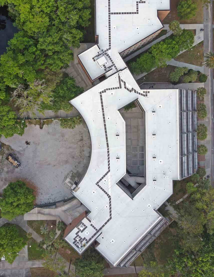
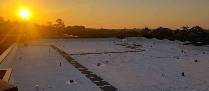
#roofingprotects Contents On Mobile Devices Use the FRSA-TRI Tile Manual to Properly Install Hip and Ridge Roof Members 22 | Considerations for Repairing Damaged Concrete and Clay Roofing Tiles 26 | Ian Leaves Broken Hearts, Hopefully It Can Also Open Eyes 12 | The Codes are Working (Hurricane Ian Preliminary Report) 20 | The Future of Roofing: Solar Partnerships30 | S.T.A.R. Awards recipient in the Low Slope category is Springer-Peterson Roofing and Sheet Metal Inc for the University of Florida School of Architecture in Gainesville.
S unshine

















S tate S olution
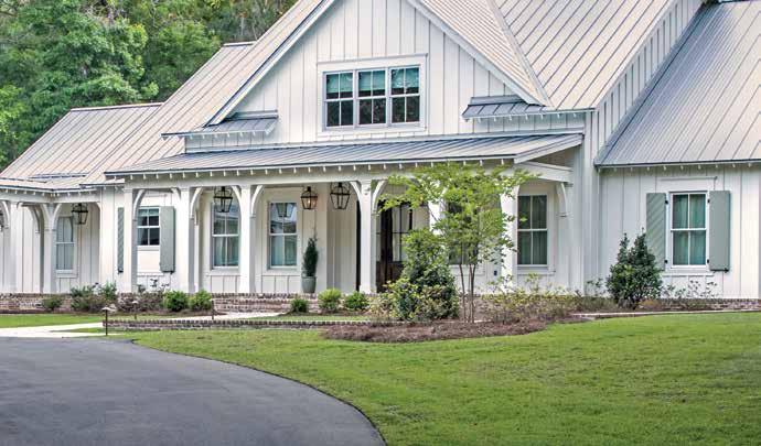
Tallahassee Residence Installing contractor: Tallahassee Roofing Architect: C. Brandon Ingram Design General contractor: Barton Construction Material distributor: ABC Supply Photo: jeffherrphoto.com
Snap-Clad
Tite-Loc Plus PAC-150 Equally strong and attractive , these metal roofing panels are available in Florida in our full line of PAC-CLAD painted steel, aluminum and Galvalume Plus coatings, ensuring that your roof will endure whatever comes its way. All panels are Miami-Dade County and Florida Building Code approved. 102 Northpoint Parkway, Acworth, GA 30102 P: 800 272 4482 F: 770 420 2533 PAC-CLAD.COM | INFO@PAC-CLAD.COM MIAMI DADE COUNTY APPROVED View the case study
2023 Charity of Choice – The Faine House
Each year, FRSA’s President and First Lady select a charity to support during their term. The charity selected usually has special meaning to them and this year’s charity is no different. FRSA President Matt Criswell grew up with a special connection to the Children’s Home Society (CHS) where Jeff Faine grew up.
About The Faine House
Veteran NFL player, Jeff Faine, and Investment Manager, Jeff Sharon, founded The Faine House. An adopted child himself, Faine envisioned supporting young adults through education and job opportunities, safe housing and financial literacy. Originally founded with CHS, The Faine House now operates as an inde pendent 501c3.
Enriching the Lives of Young Adults Without a Reliable Adult
Located in a 7,000 square foot facility in Orlando, The Faine House hosts ten private bedrooms and accepts 18 to 23-year-olds into their program who do not have access to opportunity and mentorship, including people who have aged out of the foster care system. As part of the program, each young adult sets their own financial, occupational and educational goals and participates in a curriculum designed to heal, equip and empower.
The Faine House has a trauma-informed staff and a community of volunteers, donors and regional part ners. Understanding adverse childhood experiences, they create a roadmap to increased resiliency and wholeness in mind and body. The pathway to healing and financial independence is supported by a “Pod” of community mentors who provide ongoing support, an experienced staff and an array of educational and engaging activities.
Principles of Trauma-Informed Care include:
■ Safety – Throughout the organization, residents and staff feel physically and psychologically safe.
■ Trustworthiness and Transparency – Decisions are made with transparency and the goal of building and maintaining trust.
■ Peer Support – Individuals with shared experiences are integrated into the organization and viewed as integral to service delivery.
■ Collaboration – Power differences, between staff and residents and among organizational staff, are leveled to support shared decision-making.
■ Empowerment – Resident and staff strengths are recognized, built on and validated: this includes
a belief in resilience and the ability to heal from trauma.
■ Humility and Responsiveness – Biases, stereotypes and historical trauma are recognized and addressed.
Looking to support this incredible charity? Visit www.floridaroof.com/charityofchoice. FRSA President Matthew Criswell has challened us with the commit ment to donate $1,000 for each $5,000 donated to The Faine House.
FRM
Florida
ROOFING
Circulation
Professionals
Industry-focused Digital Impressions
To find out more, contact Keisha at 800-767-3772 ext 127 or keisha@floridaroof.com
www.floridaroof.com | FLORIDA ROOFING 5
Advertise in Print
5,000 Industry
100,000
monthly
Potential Challenge to Right-to-Work Laws
Florida is a right-to-work state. When you hear the phrase right-to-work law, you may not be completely sure what it means. For example, do these laws give employees the right to work or do they give employers rights? Neither one, really.
Right-to-work laws focus on labor unions. They give workers the right to decide if they want to join unions and pay dues. Essentially, the laws prohibit unions and employers from entering agreements that require all workers to pay union fees, because this would be unfair to workers who are not in the union. Currently, these laws are in effect in 27 states. But now, Congress may be calling them into question.
Suggested Legislation
In early September, Elizabeth Warren (Mass.) intro duced a Senate bill that would ban all right-to-work laws. In the House of Representatives, Brad Sherman of (Calif.) introduced a similar bill. At this time, there appears to be little chance that the bills will gain trac tion, but it is interesting to see that the laws are being debated.
What the Supporters Are Saying
Warren, Sherman and the other legislators supporting their bills, believe that unions provide the best protec tions for workers, ensuring good working conditions and higher wages. In their mind, workers who benefit from unions should pay dues whether they are in the unions or not. Union representatives state that rightto-work laws allow “free riding.” This term means that workers who do not pay membership dues still enjoy the successes of collective bargaining.
“At a time when labor unions are growing in both size [and] popularity and delivering real wins for work ers, Democrats are making it clear that we stand in solidarity with workers everywhere, from Starbucks baristas to Google cafeteria workers and everyone in between,” Senator Warren said.
In the meantime, according to a Gallup poll, more than 70 percent of people in the United States ap prove of unions. This approval rating is higher than it has been in decades.
Objections to the Legislation
On the other hand, many Americans do not believe in unions and they object to being forced to support them financially. They oppose having to pay fees to a union they disapprove of, just so they can keep their jobs.
With these workers in mind, many lawmakers will fight the new bills – and the laws will remain in place in those 27 states.
States Without Rightto-Work Laws
What is the situation in the states that do not have right-to-work laws on the books? There, employees who decide not to join unions can opt to pay only agency fees related to collective bargaining ac tivities. These fees do not cover costs associated with political activities or lobbying.
In addition, after a 2018 U.S. Supreme Court ruling, state and public-sector unions are prohibited from charging agency fees to nonconsenting employees.
What This Means for Most Employers
More than likely, the right-to-work laws will remain in more than half of the country. However, the Biden ad ministration will continue to support laws that support unions.
FRM
The information contained in this article is for general educational information only. This information does not constitute legal advice, is not intended to consti tute legal advice, nor should it be relied upon as legal advice for your specific factual pattern or situation.
Trent Cotney is a Partner and Construction Practice Group Leader at the law firm of Adams and Reese LLP and FRSA General Counsel. For more information on this subject, please contact the author at trent.cotney@arlaw.com.
Free Legal Helpline for FRSA Members
Adams and Reese LLP is a full-service law firm dedi cated to serving the roofing industry. FRSA members can contact Trent Cotney to discuss and identify legal issues and to ask general questions through access to specialized counsel. They offer free advice (up to 15 minutes) for members. If additional legal work is re quired, members will receive discounted rates. This is a members-only benefit provided pro bono to FRSA. To use this service, contact Trent Cotney, 813-227-5501.
6 FLORIDA ROOFING | November 2022
FRSA GENERAL COUNSEL Trent
Cotney, Partner, Adams and Reese,
LLP

As Florida Reels from Ian, Elections March Forward
It’s hard to discuss politics when so many of our fellow Floridians continue to suffer following Hurricane Ian. I hope each of you and your families were safe in the storm and that you’ve encountered minimal disrup tion. Our hearts continue to pour out to family, friends, colleagues and neighbors who have lost so much. They will continue to need our support in the months and years to come. I am fortunate to frequent Bay (Panama City and Mexico Beach) and Gulf (Port St. Joe and Cape San Blas) Counties for work and the scars from Hurricane Michael are everywhere, though they are healing. As we take a minute to talk about elec tions, let’s keep Florida’s Gulf Coast in our hearts and prayers.
The Show Goes On
In the immediate days following Ian, Florida Secretary of State Cord Byrd – a former Republican House member from Jacksonville – quickly quelled rumors of a delay in November elections. At the time of pub lication for this article, tens of thousands of homes in Southwest Florida remain without power, barrier islands remain largely inaccessible and neighbor hoods in Central Florida continue to be inundated by floodwaters. Election infrastructure didn’t escape Ian’s wrath either, as entire polling sites were wiped away while many others are still being used as tem porary shelters. Elections supervisors are scrambling
for backup plans and face an uphill climb to recruit volunteers and poll workers to replace those displaced by the storm. The task of holding a “normal” election in many precincts is – to put it mildly – daunting.
Déjà vu… and a Potential Roadmap


All hope of a successful election is not lost, however.
In fact, we’ve been here be fore. Wind the clock back to mid-October 2018 and elections officials faced many of the same challenges in the aftermath of Hurricane Michael. In that year, the two biggest changes made to ease hurricane-related woes were
1. Permission for Supervisors of Elections in af fected counties to create county-wide voting “supercenters” for election day and


2. Relaxing some requirements for vote-by-mail voters to change their physical address for ballot delivery.
It’s unclear whether these specific solutions will be deployed this year, but they point to flexibility and ingenuity that may ease some of the challenges hurricanestricken voters face. Officials from the Panhandle Supervisors of Elections offices have been on the ground in Southwest Florida or in direct contact with their state and local colleagues to share storm-weathered solutions.
Now What?
If you happen to be a voter impact ed by Hurricane Ian, here are a few tips from the pros:
1. Vote by Mail: If you expect that your mail ballot may have been sent to an unreachable home, you should contact your local supervi sor’s office immediately. If you did receive your mail ballot, but decide that you would rather vote
8 FLORIDA ROOFING | November 2022
FRSA LEGISLATIVE COUNSEL Chris Dawson, Attorney, GrayRobinson
Contact Us Today For The Best Service And Lead Time 800.894.7741 | SALES@M ETALDECK SUPPLY.COM YOUR ONE-STOP METAL DECK SHOP! Metal Deck Replacement? We Have It In Stock Now! Largest Inventory In Stock for Immediate Use Variety of Deck in Stock Pick Up Or Delivery Knowledgeable Staff www.METALDECKSUPPLY.COM PROUD MEMBER
in-person, you can take the mail ballot to your polling location and have it canceled.
2. Physical Voters – Early or Election Day Voting: Keep checking your local supervisor of elections webpage and social media to find out where you’re slated to vote come November. You may be able to go to select locations for early voting, where any voter in a county can drop in at regardless of where in the county they live. Supervisors will also post updates for locations of election day precincts that are impacted by the storm. If you have any doubt on where to go to cast your vote, contact your local Supervisor’s office for help.
Vote. Vote. Vote.
Regardless of the logistics deployed, state and local officials – including Governor Ron DeSantis – have pledged to do all they can to ensure every voter is able to exercise their voting rights. We all have a role to play:
1. Vote ourselves,
2. Encourage our friends and families in the impact ed areas to vote and (
3. Provide direct support to voting operations if able.
Supervisors across the state have many volunteer roles they need to fill for November 8. Check their website or give them a call and see if there’s a spot you may be able to fill this year as we pick up the pieces from Ian. If we chip in, we can ensure an accessible and fair election despite the obstacles. Bay County Supervisor of Elections Mark Anderson recently summed it up. “Florida voters are tough,” he said. “That’s the message we’ve got to send. We’re tough, we’ll get through this, we will find a way to get the votes cast.”
FRM
Chris Dawson is an Attorney and professional Lobbyist for GrayRobinson’s Orlando office and is licensed to practice law in both Florida and Alabama. He primarily focuses on lobbying and government relations for public and private sector clients at the executive and legislative levels of state government. He is creden tialed as a Designated Professional Lobbyist by the Florida Association of Professional Lobbyists. Chris also holds two degrees in Civil Engineering and has experience in construction litigation and design pro fessional malpractice defense.
Benefits:
Technical Building Code


FRSA Self Insurers Fund

Access
FRSA Credit Union
Access to the residential roof loan program. FRSA CU can
with
Convention & Expo
Discounts
www.floridaroof.com | FLORIDA ROOFING 9
Why join FRSA? WWW FLORIDAROOF 8COM 00 767 3772 ext 142 ANNA@FLORIDAROOF.COM
to Workers' Comp with an unmatched safety and training program
on seminars Discounts on Expo booths Sponsorship opportunities
assist
auto and equipment loans and all your banking needs
support Human Resources & Legal Services Discounts on advertising Member
Industry Updates
Governor DeSantis Appoints Eleven to the CareerSource Florida Board of Directors
Governor Ron DeSantis announced the appointment of members to the CareerSource Board, including FRSA member Jerry “Les” Sims.
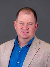
FRSA President-Elect, Les Sims, CPRC is the President of Armstrong Roofing Inc., San Mateo. With over 20 years in the roofing industry. He is on the FRSA and Credit Union Board of Directors and serves as a Trustee on the Self Insurers Fund and Educational and Research Foundation. Les is a veteran of the United States Navy.
“We’re very excit ed that Les has been appointed to the CareerSource Board. Education and training remain a crucial goal for our industry and being able to partner with CareerSource on future endeavors will benefit both organizations,” stated Lisa Pate, FRSA Executive Director. “Les has always been pas sionate about education and his involvement will serve the industry well.”
SOPREMA Inc. Acquires Furbish
SOPREMA Inc., a leading manufacturer of commercial roofing, waterproofing, wall protection and civil engi neering waterproofing solutions, has acquired Furbish, Baltimore, a sustainable development company focused on the deployment and maintenance of green roofs, living walls, stormwater management and other green technologies for high-performance buildings.
The acquisition expands SOPREMA’s presence in the sustainable solutions market and accelerates the growth of its SOPRANATURE portfolio of green roof solutions. Furbish now will have the SOPREMA Group’s resources to support its customers.
“Sustainability is at the forefront of SOPREMA’s global activities and the synergy between our two companies is obvious,” said Tim Kersey, CEO, U.S. Operations for SOPREMA. “Furbish’s green products and service offerings combined with their team’s cul ture and passion for sustaining the built environment make them a great fit for our company.”
Legacy Restoration Partners with Janney Roofing

Legacy Restoration, a leading provider of exterior restoration and remodeling services, and Janney Construction, an Orlando-based provider of exterior restoration and remodeling services, specializing in roofing, announced Janney will merge with Legacy. Legacy is a portfolio company of Bessemer Investors.
Janney’s existing management team, including CEO Derek Janney, will continue to lead the company under the Janney brand. Janney represents the continued expansion of Legacy Restoration, both geographically and into retail-based reroofing, and Legacy is excited to provide additional resources to grow the Janney brand.
10 FLORIDA ROOFING | November 2022
FRSA third page indd 1FRSA third page.indd 1 10/19/2020 10:01:24 AM AM
Scott Mullins, CEO of Legacy, said, “We are excited to welcome Derek and the Janney team, along with Janney’s retail expertise and marketing capabilities, to Legacy. The addition of Janney allows us to extend our geographic footprint into the southeast with one of the highest rated roofing organizations in the country. This is an important next step in Legacy and Bessemer’s joint goal of building the largest and high est performing exterior restoration business in the country.”
“Building Janney Roofing has been the highlight of my professional life thus far. Legacy will open us up to a broader range of products and trades and together we will be able to expand into new service areas without losing our distinctiveness. I am excited about our future together and look forward to changing our world, one roof at a time,” stated Derek Janney.
HOVER Expands Partnership with SRS Distribution to Streamline Digital Material Ordering for Contractors

HOVER, the technology company that transforms smartphone photos or blueprints of any property into a digital twin with valuable 3D data, announced an expanded partnership with SRS Distribution Inc., the industry-leading roofing and building materials distributor. The partnership allows contractors to place material orders directly from within the HOVER platform, saving them time and ensuring material quantities are based on accurate measurements.
Using accurate measurements created from HOVER’s 3D model, the Direct Ordering tool auto matically calculates material quantities and instantly prepares material lists for roofing and siding products, enabling contractors to easily place their orders with SRS via the company’s Roof Hub tool. HOVER and SRS Distribution’s Direct Ordering integration takes into
account a contractor’s unique pricing and installation preferences and offers a single, integrated digital ex perience that eliminates the need for manual entry or separate ordering and streamlines what was previous ly a cumbersome process for ordering materials.
“The adoption of digital technology within the building industry is accelerating rapidly, so we are excited to announce the renewal of our partnership with HOVER,” said Kent Gardner, Chief Revenue and Marketing Officer for SRS.
“We’re thrilled to expand on our continued part nership with SRS and offer Direct Ordering to their network of independent contractors,” said A.J. Altman, Founder and CEO of HOVER.
Saint-Gobain Acquire GCP Applied Technologies
Saint-Gobain has now acquired GCP Applied Technologies Inc., a major global player in construction chemicals. With approximately $1 billion in revenue in 2021 and 1,800 employees working on 50 produc tion sites in 38 countries, GCP Applied Technologies provides a global platform with established success in cement additives, concrete admixtures, infrastructure and commercial and residential building materials.
This acquisition is a major milestone in establishing Saint-Gobain’s leading position worldwide in construc tion chemicals and furthers the Group’s strategy as a worldwide leader in light and sustainable construction.
The specialty building materials business in North America will be integrated into the CertainTeed busi ness serving local customers in its region. All other businesses, consisting of mainly concrete admixtures and cement additives will be combined with the Chryso business and be part of the High Performance Solutions segment.
FRM Double Your Giving December 1 Only All donations to the FRSA Educational & Research Foundation made on December 1 will be matched by Trent Cotney Join us at 10 am December 1 www.floridaroof.com/rcs-zoom Donate at www.floridaroof.com/2x
Ian Leaves Broken Hearts, Hopefully It Can Also Open Eyes
Mike Silvers, CPRC, Silvers Systems
I’m writing this article rough ly a week after Hurricane Ian battered the state as one of the largest and deadliest hurricanes to hit Florida since 1935. Coincidentally, last month I discussed the potential of a similar scenario to Ian and the impact it could have on Florida’s ongoing property insurance cri sis as well as its post-hurricane economy (see October FRM - If You’re Not Concerned, You May Not Be Paying Attention –floridaroof.com/frm10-22p16). I talked about a major storm hitting a highly developed area such as metropolitan Miami or the Tampa Bay region.
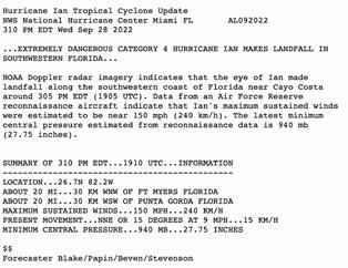
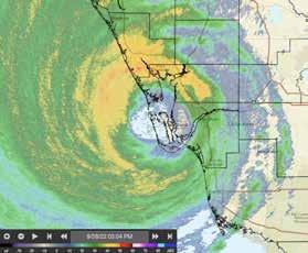
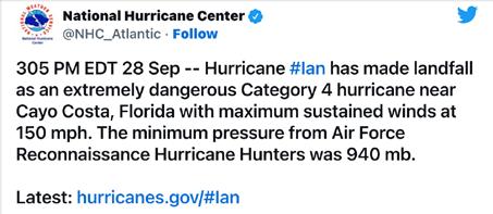
As Ian approached, it looked as if that might happen. My family watched with great concern as the path at one point had the eye passing over our home in Manatee County, which is on the south end of Tampa Bay. But as the storm progressed, it started moving more toward the east, just as Hurricane Charley had done in 2004. We were obviously relieved that we wouldn’t see the worst of the storm, but those feelings of joy were mixed with some guilt knowing what our neighbors to the south were about to endure. I am heartbroken by the devasta tion Ian caused and even more so by the staggering loss of life left in its wake. So many of us live near the coast because we are drawn here by the beauty and serenity that the marine envi ronment offers. To think that the
and FRSA Director of Technical Services
12 FLORIDA ROOFING | November 2022
Inc.
4 4 4 4 4 5 Category 4 and 5 US Gulf Coast Landfalls Since 2017 Harvey 130 mph 937 mb Laura 150 mph 939 mb Ida 150 mph 931 mb Michael 160 mph 919 mb Ian 150 mph 940 mb Irma 130 mph 931 mb
same water that attracts us also has the ability to en gulf us in such an unforgiving way is sobering.
Post Ian Damage Survey
If you’ve followed my column, you know that I am committed to conduct post-hurricane roof damage observations within the first week after a major storm hits Florida. I’ve done so after Irma, Michael and now Ian. What I’m able to see adds to the knowledge gained by responding to previous storms as a contrac tor. Getting to the scene early is important. Temporary roof repairs and tarping begin almost as soon as the winds decrease. This obviously makes viewing roof damage much more difficult if not impossible. After hurricanes, I also review as many pictures and reports as I can find in the media as well as pouring over NOAA satellite imagery of the damaged areas (storms.ngs. noaa.gov).
The NOAA site allows us to look for roof damage and pinpoint areas to inspect. If you use the site, you will need to zoom in very close to the dark areas on the map to see individual buildings. If you have the opportunity, please share with me any roof dam age pictures you take and any of your observations (silvers@floridaroof.com). The storm surge that hit Fort Myers Beach and bulldozed most structures in its path reminded me how Michael had done the same in Mexico Beach. Many buildings were reduced to nothing but concrete slabs and debris. A literal army of researchers (Army Corp of Engineers and FEMA Mitigation Assessment Teams) and others will evalu ate the damage from storm surge and flooding. They will come to conclusions based on their observations and make recommendations to reduce the hazard by amend ing the building code. Further strengthening and raising of buildings that are in the flood plain will be proposed and, most likely, implemented. Beachfront establishments that have offered the famil iar experience of dining and drinking on a beachfront patio, as well as any other near grade structures, will not be allowed to rebuild at ground level, for ever changing our beachfront landscape.
The roofing industry’s mis sion obviously does not involve storm surge or flooding. Our trade is tasked with keeping rain outside of buildings by keeping roof coverings in place during high wind events. We are expected to do so on any structure that can endure the
wind load or flooding that these storms bring. It is a daunting challenge, but one we will have to continue to pursue to ensure we are able live in what many of us view, even with the threat of hurricanes, as paradise.
We need to learn from observing post hurricane what worked and what didn’t. With Ian, that meant
www.floridaroof.com | FLORIDA ROOFING 13
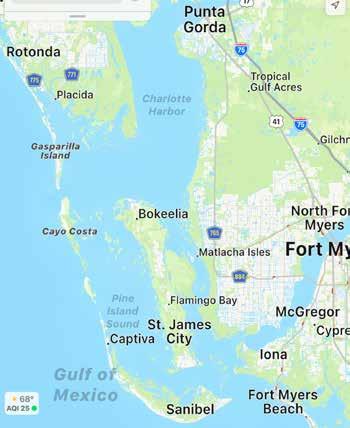
looking at damage outside of the storm surge areas, but still within the areas impacted at near-design wind speeds. Ian’s eye made landfall near Cayo Costa, which is just north of Captiva on the north end of Sanibel and Captiva Islands. North of Cayo Costa is Boca Grande Pass and Gasparilla Island. I have spent many days tarpon fishing, boating and beaching it in this area all my life so I’m very familiar with it. My wife and I were married there. During my visits there, some of that time was spent at a favorite beach establishment called South Beach which is very near the pass. It burnt to the ground during the storm – the fire depart ment was unable to deploy during the high winds – I’ll miss going there. Unfortunately, this also occurred in other areas to residential structures. This area was north of where Ian’s eye made landfall, so storm surge wasn’t much of an issue, however wind certainly was. That is why I chose this area to make my observations. It was accessible and had structures dating from many decades old up to those still under construction and everything in between.
Sorry to say, I was turned away at the toll booth leading to Gasperilla Island and Boca Grande by sever al guardsmen with assault weapons strapped across their chest. I understood that the primary purpose of post-storm deployment must continue to be preserva tion of life, evacuations and rendering aid. However, as much as I understand the need to limit access to these areas, if we don’t allow some timely observations to take place, we will severely limit our ability to learn important lessons from these devastating events. We access these areas with no or minimal interference. Hopefully in the future, access can improve as we learn to address the overall cost and disruption these events cause and understand that the knowledge gained is worth the slight inconvenience that a few experienced observers might cause.
Being turned away when one knows the valuable information that is available is disappointing but one bump in the road shouldn’t stop the journey. The Placida area, just west of Gasparilla Island and north of the mouth of Charlotte Harbor, also experienced very high winds and access to most neighborhoods was allowed. My initial thoughts, based on what I saw, were similar to those formed during Irma and Michael. Newer construction – including roof coverings – that
were designed and installed according to the latest several editions of the Florida Building Code (FBC) did very well overall.
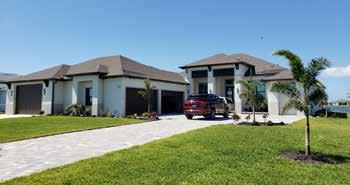
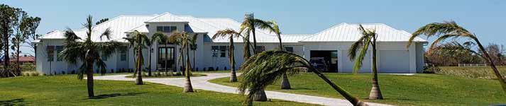
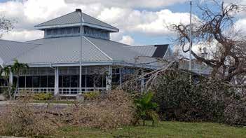
From a visual observation, many roofs of all types appeared to be unscathed, but most roofs in these areas did have some degree of damage. On some new er asphalt shingle roofs where the field of the roof did well, there were common failures at the hip and ridge. Those same conditions on newer tile roofs did better than before the improved hip and ridge attachment methods became the standard based on the FRSA-TRI Florida High Wind Concrete and Clay Tile Installation Manual. Metal roofs, overall, appeared to perform well with most observed failures occurring at the rakes and other trim. This observation should be weighted by the fact that the trend towards metal roofing has developed relatively recently. This trend tends to make the existing metal roofs on average newer than many other roof types that have been used more prevalently in the past.
It is clear that newer roofs of all types, when in stalled to current codes and standards, performed better than the same roof types of similar age have done in previous high wind events. I did see some indi cation during review of available media similar to what I saw firsthand in Irma and Michael. It appears that through-fastened metal roofs, installed as recovers, experienced some whole roof section (such as hip end) failures. It may be that the inability to address renailing of the sheathing may be more of a concern when using this installation method.
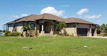
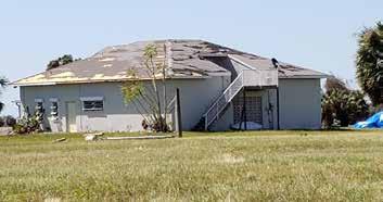
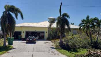
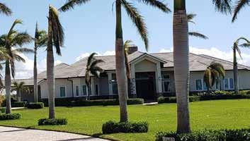
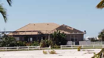
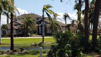
Below and on the following pages are several pictures taken during my assessment. These pictures serve as an archive to help remind me what I observed following the hurricane.
14 FLORIDA ROOFING | November 2022
Increase Your Chances To Weather Any Storm with an Eagle Concrete Tile Roof


Hurricane season is here.
Protect your next residential or commercial roofing project with concrete roof tile, the best defense against high winds, tropical storms and hurricanes. Thanks to its inherent durability, concrete tile roofs—when properly fastened to code—can withstand sustained windspeeds of up to 180mph. In addition, they are hail and impact tested and offer a non-combustible Class A fire rating. Protection from the elements begins with an Eagle Concrete Tile Roof.
Our Tile Is:
Fire Tested

High Wind Tested
Freeze Thaw Protection*

*Exludes color bonded slurry tiles
Hail/Impact Tested
For even greater peace of mind, consider fortifying the overall roofing system with The Dual Fix Hybrid System*.
This installation method increases the durability of any roofscape by merging the trusted advantages of mechanical fasteners, or tile screws, with the improved uplift resistance of single-component tile foam adhesive for greater attachment strength. When properly installed, this technique provides the highest uplift protection from winds associated with a category five hurricane.
*Mechanical Fasteners and Tile Bond Roof Adhesive, products associated with The Dual Fix Hybrid System, are not products of— nor warranted by—Eagle Roofing Products.
To learn more about our products and The Dual Fix Hybrid System, contact your local Eagle Account Representative or visit: eagleroofing.com
connect with us!
eagleroofing.com


16 FLORIDA ROOFING | November 2022

ADAMSANDREESE.COM // TRENT.COTNEY@ARLAW.COM // 866.303.5868 PROUDLYREPRESENTING THE ROOFING INDUSTRY MAIN OFFICE: TAMPA
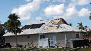
The picture above appears to provide an excellent example of the benefits of a self-adhered under layment applied direct to deck. Earlier street view pictures of this house show an existing tile roof. That indicates that the house may have been very recently reroofed with shingles. If so, the seal strips on the shin gles may not have fully bonded. Other shingle roofs in the same area didn’t seem to have such extensive failures. I hope to get additional information on this particular house to confirm my initial observation but, either way, it does demonstrate the value of an effec tive secondary water barrier resistance.
Hurricanes and the destruction they leave behind are truly heartbreaking. Hopefully, the agencies who
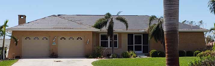
are in charge after these disasters can open their eyes to the need for our industry and those who are active in the building code process to learn all we can from them, to help reduce the amount of heartbreak and insurance claims in the future.
 FRM
FRM
Mike Silvers, CPRC is owner of Silvers Systems Inc., and is consulting with FRSA as Director of Technical Services. Mike is an FRSA Past President, Life Member and Campanella Award recipient and brings 50 years of industry knowledge and experience to FRSA’s team.
18 FLORIDA ROOFING | November 2022
A p p l y O n l i n e w w w . f r s a c u . o r g o r c a l l 8 7 7 6 5 7 7 2 1 2 Roof Loans to Assist With Hurricane Deductibles Contact us for more information
FRSA Members Deliver PAC Contributions to Candidates
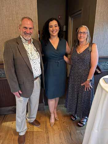
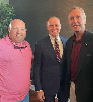
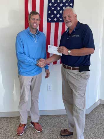
Each year, FRSA designates a portion of membership dues to the FRSA Political Action Committee (PAC). Among its activities, the PAC provides donations to Florida political candidates who are in leadership roles, are industry allies or who have a construction or roof ing background.
FRSA has adopted the strategy of having members deliver campaign checks to candidates in person, to help put a local face on the Association and the sup port it provides.
Several members recently delivered checks to candidates, including: (right) FRSA President Matt Criswell with Representative David Smith (R-Winter Springs, House District 38) and former Senator David Simmons; (below) FRSA Secretary-Treasurer Tibor Torok and his wife, Toni, with and Alexis Calatayud (R-Miami) who is running in Senate District 38; (be low right) FRSA member volunteer Dell Jackson with Representative Jay Trumball (R-Panama City Beach, House District 6).
For more information about the FRSA PAC, contact Mike Reed at 800-767-3772 ext. 169 or reed@floridaroof.com.
FRM
www.floridaroof.com | FLORIDA ROOFING 19
The Codes are Working: Newer Buildings Tended to Protect Better During Ian
John Hellein, FRSA Educational & Research Foundation Director
At the October Florida Building Commission meeting in Gainesville, Dr. David Prevatt of the UF Department of Civil Engineering, presented preliminary findings to the Commission on the effects of Hurricane Ian to buildings in the area of impact.
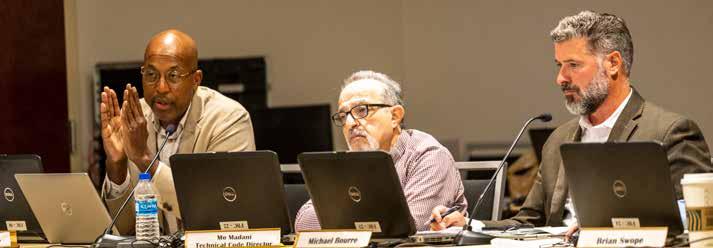
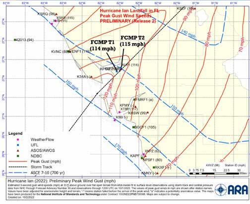
Given the extent of the damage from Ian, it was sobering to hear Dr. Prevatt characterize the storm as a “moderately strong wind event.” Looking at the reported wind speeds around landfall, we can under stand the reason for this characterization: despite Ian’s 150 mph sustained winds – which apparently occurred offshore – the top three-second sustained gusts were around 120 mph. Prevatt noted that the actual wind speeds experienced onshore were significantly below the design speeds, which were in the 150-to-160 mph range (see map at the bottom of page 13).
Newer Construction Performed Better Municipal buildings and schools in the area of impact
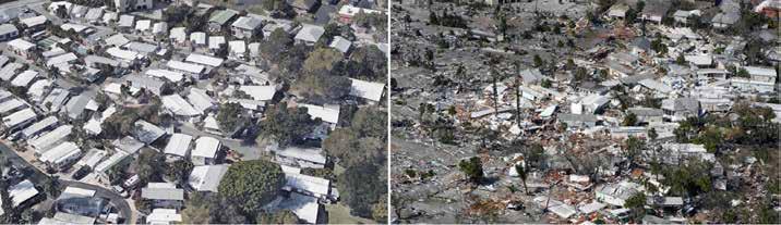
performed very well according to Prevatt and, in general, newer construction – structures permitted or improved under the Florida Building Code that was first implemented in 2001 – performed better than older construction. Prevatt’s presentation included the below photo of Fort Myers Beach, posted by Professor Michael Bruneau of the State University of New York. The photo indicates the years in which houses, or what remains of them in many cases, were built or improved. The circled, still standing house directly on the beach was built in 1990 but “redone and expand ed” in 2020. A subsequent post by Bruneau listed, by year built or improved, many of the properties in the photo (the ones he was able to get information on) and whether or not the home on the property survived.
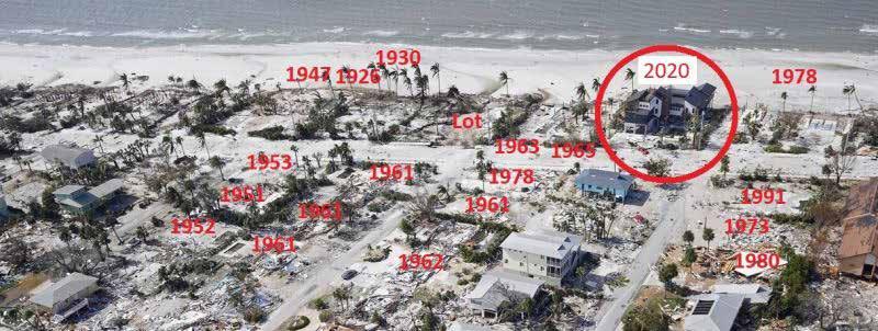
■ Of the 13 listed properties that survived the storm, 12 of them were built or improved after 2013.
Continued on page 25
20 FLORIDA ROOFING | November 2022
Dr. David Prevatt (left) presents preliminary findings for Hurricane Ian at the October Florida Building Commission meeting in Gainesville.







Providing Operational Security www. FiberTite .com FiberTite is manufactured exclusively in the USA by Seaman Corporation. 1000 Venture Blvd. Wooster, OH 44691 • www.SeamanCorp.com World’s Most Powerful Brands for the Congratulations to FRSA Convention and Expo 100 YEARS OF INDUSTRY LEADERSHIP!
Use the FRSA-TRI Tile Manual to Properly Install Tile Hip and Ridge Members
 Manny Oyola, Jr., Technical Manager Eastern Region FL, Eagle Roofing Products
Proper installation of hip and ridge roof tile is likely to be the difference between a roof that withstands the uplift pressures of a high wind event and one that fails to protect the building it covers. Let’s look at import ant components of properly installed hip and ridge tile.
Establishing the Wind Zone Requirements
Before designing and installing a roof, we must first know what the design speed requirements are for its location. Wind speed calculators available online (for instance, https://asce7hazardtool.online) can work very well in helping you determine the design require ments; however, it is critical to verify the building department’s set compliance requirements in the authority having jurisdiction. Once you have estab lished design requirements, you can choose from one of four types of hip and ridge tile attachment methods. These methods are covered starting on page 14 of the FRSA-TRI Florida High Wind Concrete and Clay Tile Installation Manual and are code-compliant, by ref erence, in the standard region of the Florida Building Code.
Once you have selected which type of material you will use for the structural support (see Hip and Ridge Attachment table below), you can then use the corresponding instructions from the Tile Manual. However, before we look at the methods listed in the Tile Manual, it is important to note that an installation method typically used in the field does not follow the methods listed in the Tile Manual:
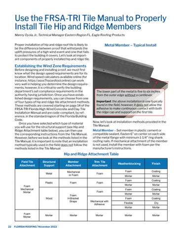
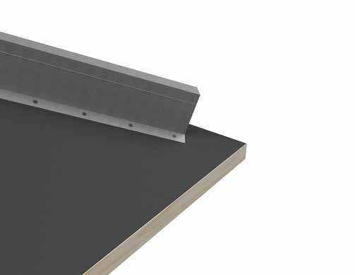
The lower part of the metal is five to six inches from the outer edge without a cantilever.
Important: the above installation is one typically found in the field, however, it does not allow the adhesive to make continuous contact with both the ridge cap and support on the first tile.
Now, let’s look at installation methods provided in the Tile Manual:
Metal Member – Set member in plastic cement or compatible sealant. Fasten 6” on center on each side of the metal flange with minimum 1-1/4” ring shank roofing nails. If mechanical attachment of the member is not used, install the member with foam per the manufacturer’s instructions.
Foam
Mortar Mortar
Foam
Mortar Mortar
Mortar Mortar
Foam
Flexible Dry Mortar Mortar
22 FLORIDA ROOFING | November 2022
Field Tile Attachment Structural Support Member Attachment Trim Tile Attachment Weatherblocking Finish Foam Mechanical Mortar Metal Mechanical or Foam Foam
Coating
Plastic Foam Foam
Coating
Wood Foam H-Bracket Straps Foam Foam Coating
Mechanical with Adhesive
Coating
Foam Mortar Mortar Mortar Mortar Mortar Mortar Hip and Ridge Attachment Table
Seal All Nail Penetrations with Compatible Roof Cement
Unless the Underlayment Meets ASTM D-1970 Sec. 7.9.
Note: Stacking of Nailer Boards may be Used. Maximum Thickness of 2” per Additional Nailer Board.
STRUCTURE HIP AND RIDGE SUPPORT (from Tile Manual, page 41)
OPTION: CODE APPROVED PRE BAGGED MORTAR
Point Mortar to Desired Finish
FHW‑18
Install Hip and Ridge Tile in a Continuous Bed of Code Approved Pre-Bagged Mortar. Mortar Shall Completely Fill the Entire Cavity and Provide a Bond with the Hip and Ridge Tile.
Note: SSTD 11-99 Code Compliant Documentation shall be provided when a continuous bed of code approved prebagged mortar is used for structural support in the installation of hip and ridge roof tile.
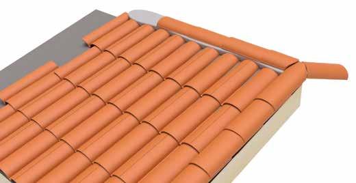
Plastic Member – Install the member with foam per the manufacturer’s instructions.
If using a structural member, choose one of the following:
NOTE – Drawings are for illustrative purposes and do not reflect all methods of installation. Please refer to written text.
Wood Member – Fasten 18” on center with four #8 screws per metal strap or H-bracket. Each attachment point shall have two fasteners on each side of the wood member. The fasteners shall be spaced evenly on the metal strap or H-bracket with the attachment holes parallel to the hip or ridge.
The straps and H-brackets shall be a minimum of 26 gauge. All materials must be compatible with each other. If mechanical attachment of the wood member is not used, install the member with foam per the manufacturer’s instructions.
mortar – When using foam or mortar field tile attachment, mortar can be used as a structural attachment. Place a full bed of pre-bagged mortar under the entire tile. Each tile must be fully embedded into the mortar. The field tile secured to the underlayment along with the mortar on each trim tile creates the structural bond. The entire cavity under the trim tile should be filled with approved mortar (see Drawing FHW-18 above).
Starter Tiles
Based on feedback we have received from contrac tors in the field, it seems that the following statement in the tile manual is often ignored or misunderstood:
Starter Tiles – All starter tiles must be secured at both ends of the tile either with mechanical fasteners, mortar and/or adhesive.
When the field tile is installed with foam or mor tar, the starter tile may be installed with an approved mortar.
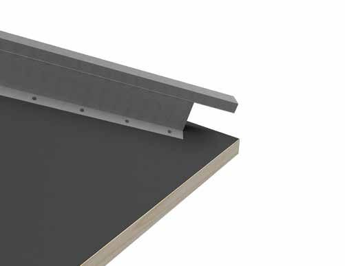
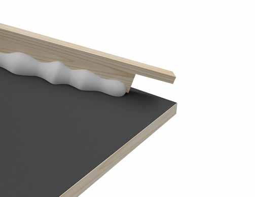
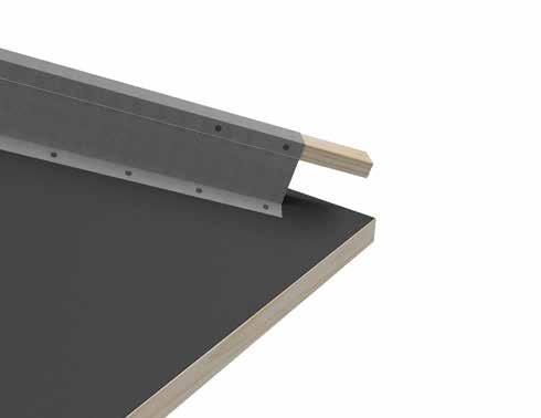
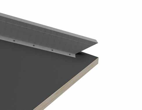
Metal Member – Place foam under starter tile per manufacturer’s recommendations or secure the head of the tile with one #8 screw and apply adhe sive in the gap between the structural support and the tile. The member may need to be cantilevered to provide a base for the adhesive. The starter tile must make contact with the adhesive. See manufacturer’s recommendations.
FRSA-TRI Florida High Wind Concrete and Clay Tile Installation Manual – 6th Edition 12/31/20
One inch from the lower edge of the hip.
Five inches from the lower edge of the hip.
This method incorporates a four inch cantilever and the outer edge is within one inch of the outside corner from the hip.
www.floridaroof.com | FLORIDA ROOFING 23
This method incorporates a four inch cantilever cut back at a 45º angle and the outer edge is within one inch of the outside corner from the hip.
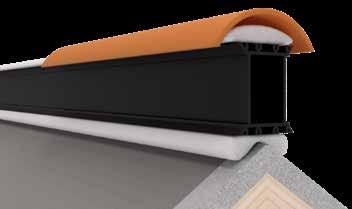
Plastic Member – Place foam under starter tile per manufacturer’s recommendations.
Plastic Member
Install extended wood support cantilever four inches into and out of the metal and fasten with two #8 screws on each side of the metal support.
Wood Member – Place foam under starter tile per manufacturer’s recommendations or drill a hole in the lower third of the starter tile and secure with a me chanical fastener into the wood member a minimum of 1”. Seal the head of the fastener with a UV-resistant sealant. Adhesive may be used in lieu of a fastener as long as the wood member has been cantilevered to provide a base for the adhesive. The adhesive be tween the structural support and the tile must make continuous contact with both the structural support and the tile. See manufacturer’s recommendations.
The important word, which both the metal and wood structural supports have in common, is “canti levered.” A cantilever can be achieved using one of several methods while still meeting the intention of the manufacturer’s recommendations.
24 FLORIDA ROOFING | November 2022
Five inches from the lower edge of the hip.
One inch from the lower edge of the hip.
The lower part of the metal is five to six inches from the outer edge of the hip.
Plastic ridge support used with code-approved roof tile adhesive.
The lower part of the wood is four inches from the outer edge of the hip.
One inch from the upper edge of the hip.
One inch from the lower edge of the hip.
One inch from the upper edge of the hip.
Conclusion
Using one of the hip and ridge attachment methods from the FRSA-TRI Tile Manual provides codecompliant options for installations in the standard Florida Building Code region. Proper installation can mean the difference between a home that with stands a high wind event and one that does not.
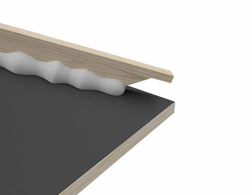
The lower part of the wood is four inches from the outer edge of the hip.
FRSA members receive one complimentary copy of the FRSA-TRI Tile Manual and additional cop ies are available at a discounted rate of $15 each. Members may also contact FRSA technical support at 800-767-3772 or silvers@floridaroof.com with code and building related questions about tile and other roof systems. The Tile Manual is currently in its sixth edition, using the ASCE 7-10 wind specifica tions. A new seventh edition will become effective a little over a year from now (12/31/2023) and will use whichever ASCE 7 specification is adopted by the Florida Building Commission, probably ASCE 7-22. Many thanks to the members of the FRSA-TRI com mittee who dedicated much time and effort drafting the seventh edition Tile Manual.
FRM
Hurricane Ian Report, continued from page 20
■ Of the 16 properties that were destroyed, all of them were built before 1979.
Of course, the physical forces at work from wind and storm surge during a hurricane are complex, so it is typically difficult to draw crystal clear conclusions, but there is strong evidence that newer construction, built under stricter codes, performed better than older construction.
Unsecured Mobile Homes
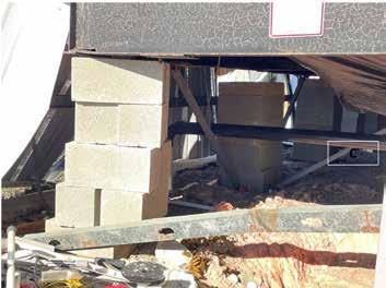
Finally, the Commissioners heard about the “extreme damage” caused by wind and flooding to mobile homes residing on stacked and unsecured cinder blocks. The reality faced by the people living in such mobile homes – as well as by the rest of us – is that they are the people least in a position to cover the ex penses involved in improving the safety of the homes in which they live. Possible solutions include programs to help residents strengthen the foundations of their
mobile homes and forbidding future placement of mobile homes in flood prone areas.
FRM
www.floridaroof.com | FLORIDA ROOFING 25
Post Storm Event – Considerations For Repairing Damaged Concrete and Clay Roofing Tiles
Tile Roofing Industry Alliance
The Tile Roofing Industry Alliance (TRIA) is an industry trade association comprised of roof tile manufacturers, roofing contractors and suppliers dedicated to the advancement of tile roofing. Properly installed tile roofs last longer than most comparable roof systems and are repairable in most cases if exposed to flying debris and other natural disaster related activities.
In addition to curb appeal, permanence and energy savings, one of the greatest advantages that tile roof ing offers is its inherent repairability. A typical tile roof system is comprised of thousands of individual tiles, all of which may be safely removed and replaced without impacting the integrity of the roof system.
The guidelines included in this technical brief (#2022001) are designed to assist the user with the evaluation of a storm damaged tile roof and to help the user de termine whether to repair or replace the roof. The TRI Alliance strongly recommends having a trained and state-licensed professional evaluate the condition of the underlayment and roof decking when considering repairing or replacing a roof to identify all of the concerns, including the discussions of coverage for workmanship in affected areas for both repair and harvesting.
Post-Storm Frequently Asked Questions
How do I know if my roof tiles received storm related damage? Roof tile damage is typically visible to the naked eye. Broken roof tiles often result from large hail stones and flying debris such as tree limbs, yard decor, etc. Broken tiles rarely occur as a result of wind exposure. In order to ensure the integrity of your tile roof, broken roof tiles must be properly repaired or replaced.
Who should I trust to evaluate my damaged tile roof? The TRI Alliance recommends consulting a credible Florida licensed roofing contractor that has experience with the regional code requirements.
How do I know that my roof can be repaired? This document contains industry endorsed procedures that help insurance representatives, roof consultants and roofing contractors determine whether a damaged tile roof should be considered for repair or for replacement. It should be left to a trained professional to properly evalu ate repair options.
My neighbor received a new “free roof” – how do I get one? Too often, the promise of a free replacement tile roof is propagated by individuals motivated by signif-
icant compensation that may occur in a post-storm environment. These guide lines herein may assist in determining whether a tile roof may be repaired or be replaced, but the cost is dependent upon many factors that will be specific to each case.
What if the roof tiles on my home are not currently produced? Are there other tiles that will “fit”? Every damaged tile roof must be evaluated on a case-by-case basis. Over the past 50-plus years, hundreds of tile colors and shapes have been produced and marketed through out North America. If the exact shape and color of tile on your roof is not actively produced or readily available, third-party producers may be able to supply reasonable facsimiles. Another alternative may be the “Harvest and Repair” method outlined in this document. (Note: the Florida Building Code allows the use of salvaged roof tile in certain circumstances; see FBC Existing Building, Section 706.5).
What is the difference between a repair and a harvest and repair? A tile roof may be easily repaired if the exist ing roof tiles are available from the original manufacturer, a vendor that inventories older tiles or a specialty manu facturer of replica tiles that can fit and interlock with the existing roof tiles.
The Harvest and Repair method may be utilized when existing tiles are no longer produced or suitable interlock ing alternative tiles are not available. In this instance, roof tiles may be removed from inconspicuous areas of the roof (non-street facing) for the purpose of replacing the street facing visible damaged tiles. Harvested tiles may be replaced with tiles of similar shape and, where possi ble, a similar color (see diagrams on following pages).
What role does the underlayment play in the watertight ness of my tile roof? In most cases, the underlayment acts as a secondary water barrier. Regardless of its age, underlayment that has not been exposed to the elements will likely continue to shed water if needed. The TRI Alliance strongly recommends a qualified roofing con tractor inspect the condition of the underlayment prior to conducting a tile roof repair. New or harvested roof tiles should not be installed over compromised underlayment regardless of the age of the roof system.
For more information about tile roof repairs and eval uating the condition of underlayments, please see TRI’s YouTube Channel: www.youtube.com/c/tileroofingorg1.
26 FLORIDA ROOFING | November 2022
Example of Tile Roof Damage Created by Wind-Borne Debris
A roof (as illustrated below) that experiences minimal damage may be repaired or the Harvest and Repair meth od may be used in accordance with the Florida Building Code, which states:

Not more than 25 percent of the total roof area or roof section of any existing building or structure shall be repaired, replaced, or recovered in any 12-month period unless the entire existing roofing system or roof section is replaced to conform to requirements of this code.
can be used with similar, but different field tiles. Spare tiles may be stored by owner for future repairs.
Potential Harvest Areas
Exception: If an existing roofing system or roof section was built, repaired, or replaced in compliance with the requirements of the 2007 Florida Building Code, or any subsequent editions of the Florida Building Code, and 25 percent or more of such roofing system or roof section is being repaired, replaced, or recovered, only the repaired, replaced, or recovered portion is required to be constructed in accordance with the Florida Building Code in effect, as applicable. Pursuant to s. 553.844(5), Florida Statutes, a local government may not adopt by ordinance an administrative or technical amendment to this exception.
Total roof area may be determined via field measure ment, or via commonly available aerial measurement programs.
Example of a “Harvest Area”
When tiles of exact fit and finish are not available for necessary repairs, but tiles of similar shape and finish are available AND the roof design possesses an area where hip and ridge tiles provide a natural break between roof planes, the roof tiles may be harvested from “hip to hip” or “gable to gable” and used to facilitate street visible re pairs. Hip and ridge tiles cover the cut edges of field tiles, so they don’t require interlocking with original tiles and
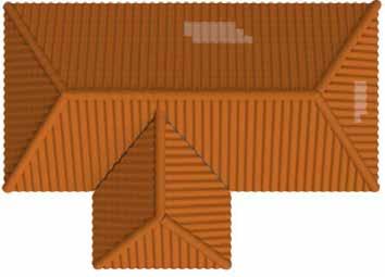
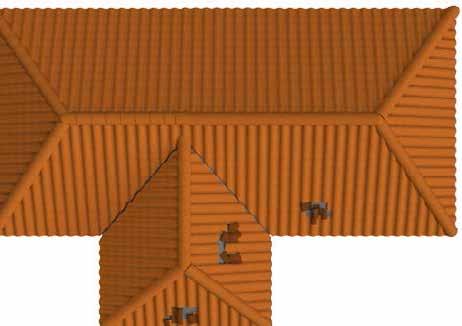
■ Plane or roof area that was removed and installed with new tiles (when similar tiles).
■ If new tile design, then remove entire roof plane (hip to hip).
■ New tile may appear different in color when viewed up close but will blend into the rest of the roof when viewed from a distance.


In most instances, the repaired tiles will not match the existing tiles due to naturally occurring aging. Your roof ing contractor may recommend color coating the repair roof tiles to assimilate with the majority roof tiles to the best of his or her ability. Color coating repaired roof tiles does not affect the integrity of the tile roof.
As a non-profit industry association, the TRI Alliance does not perform formal field evaluations or assess ments of roof installations for building owners. Trained

www.floridaroof.com | FLORIDA ROOFING 27
Example of Completed Repair
and licensed roofing professionals can provide the required forensic inspections to determine the actual condition of a roof after a weather or wind event. The trained professional will need to perform a full assess ment to determine if the roof’s condition is in compliance with any and all applicable codes.
Code Development
The development of and updates to building codes in order to meet wind uplift design requirements have been an ongoing process. The TRI Alliance has reviewed these updates after each code cycle to address the new revisions that might impact concrete and clay roofing tiles. TRI Alliance’s code-approved installation guides in clude the necessary information for meeting these code requirements.
Unfortunately, misinterpretations of codes, typically as a result of insufficient information or misunderstanding in some cases, has led to confusion in the marketplace. One example is a claim that if the nose of the tile is lifted over two inches the entire roof is not code compliant and must be replaced. This is not representative of testing protocols in the code language. To better understand, a brief history on the code development for fastener uplift resistance is provided. It should be noted that broken tiles on the roof does not necessarily indicate evidence of wind uplift of tiles. Rather, in a high wind event, tiles are typically broken by impact from airborne debris.
The TRI Alliance worked collaboratively with building officials to establish minimum requirements for instal lation of concrete and clay roofing tiles to comply with the various codes. These minimum requirements and additional code and product information are included in TRI Alliance’s code approved installation guides, including the Florida High Wind Concrete and Clay Tile Installation Manual, adopted by all TRI Alliance producing members.
TRI Alliance Industry Research
After Hurricane Andrew in 1992, the tile roofing indus try worked in partnership with various building officials to develop new building codes and test protocols to help improve performance of roofing tiles in high wind designated areas such as Florida. Those efforts led to the formal building codes in place today. TRI Alliance’s industry-based and code approved installation guides summarize these efforts in the various tables to provide the engineered wind uplift forces and resistance values for various tested fastening options. This information helps the design professional and roofing community meet the required codes for specific design wind speeds. All this information was based upon extensive research performed in 1988 at the Redland Research Centre in the UK, one of the few full-scale wind tunnel research centers in the world capable of achieving wind speeds in excess of 130 mph for roofing materials.
This research quantified actual wind performance of roofing tiles on a steep slope roof design resulting in spe cific uplift resistance values for various fastening options.
In addition, the TRI Alliance performed product specific uplift resistance testing in laboratory controlled testing facilities on newly constructed plywood roof decks to generate the full table of values for mechanical fastening methods utilizing specific nails, screws or clips.
The laboratory wind tunnel testing conducted by the TRI Alliance concluded that sustained wind forces that lift the nose-end of an individual tile up to 2” would per form to our fastener recommendations. The mechanical fastening values found in the TRI Alliance’s installation manuals are in accordance with the code referenced test standards.
Summary
The code standards provide specific installation condi tions and uplift load application at specific attachment points on a roof tile. Roofing tiles, when installed correct ly have been able to withstand or exceed code design wind speeds where the tiles are not lifted more than two inches by the sustained wind forces. Other field applied mechanical maneuvers such as prying or pulling of tiles do not accurately represent the permanence of the tile when subjected to sustained wind events.
Individuals with a potentially damaged roof should first contact either the manufacturer, if they are still in business, a registered roof consultant or a TRIA trained roofing contractor. Our contractors can be found at www.tileroofing.org.
For more information on this or any other topics, please visit our website at www.tileroofing.org or email us at info@tileroofing.org.
Florida Building Code Definitions
ROOF SECTION in Section 202, Florida Building Code, Existing Building 7th Edition (2020) states: ...related work which involves removal and installation of components for the purpose of connecting repaired areas to unrepaired areas (roof areas required for a proper tie-off) shall not be considered part of the roof repair in question and therefore such related work shall not be counted toward the 25 percent threshold stated in Section 706.1.1 Florida Building Code, Existing Building, 7th Edition (2020).
ROOF SECTION. A separating or division of a roof area by existing expansion joints, parapet walls, flashing (excluding valley), difference of elevation (excluding hips and ridges), roof type or legal description; not including the roof area required for a proper tie-off with an existing system.
FRM
TRI Alliance, 2150 N 107th Street Suite 205 Seattle, WA 98133, phone: 206-209-5300, email: info@tileroofing.org and website: www.tileroofing.org. Technical brief #2022-001 reprinted with permission of TRI Alliance.
28 FLORIDA ROOFING | November 2022
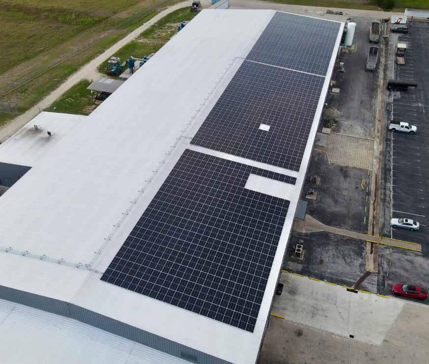
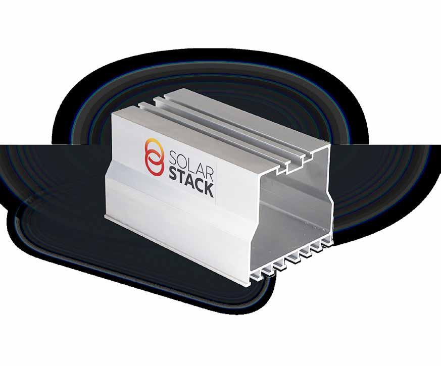
The DAMAGE-FREE Solar Panel Mount solarstack.com US PATENT No 8,104,231 • US PATENT No 8,615,954 • US PATENT No 9,315,999 • US PATENT No. 11,326,736
The Future of Roofing: Solar Partnerships
John Fay & Becca Choi, Infinity Solar
Solar energy is prospering and business-savvy roofing contractors are taking action. As the solar industry booms, partnerships between roofing contractors and solar companies offer various benefits for all parties, including business growth, access to new customers, a positive customer experience and environmental benefits.
Many roofers and solar installation teams have already joined forces, but there are still growth oppor tunities for those who haven’t yet secured a business partner.
Roofing and Solar are Becoming Inseparable for Homeowners
The U.S. solar market was valued at $33 billion in 2021 and is on the rise. The growing need to supply power to electric vehicles and the collective desire to move away from fossil fuels are growing trends that will serve as catalysts for rapid solar energy growth in Florida for the coming years. The solar industry’s goal is to produce 30 percent of all energy in the U.S. by 2030.
Meanwhile, roughly 2.3 million single-family, standalone homes will need a new roof each year. Of these homeowners, a majority already perceive value in installing solar panels on their homes, but many are unaware of the process and costs involved. Roofers who make the choice to introduce a solar provider who then works to educate homeowners, will position all parties involved to benefit. Plus, of the homeown ers who seek out a solar company first, roughly 20 percent of homes will require a new roof before solar installation is possible. By partnering with a solar com pany, roofing companies gain access to a motivated customer base through warm referrals.
Homeowners Agree on the Benefits of Installing Solar Panels
According to Forbes Magazine, 75 percent of home owners would like to switch to solar in the next five years and only a third have hesitations regarding the upfront cost of solar installation.
Considering many solar installation companies currently offer no money down options to homeown ers, the benefits of installing solar are beginning to outweigh the costs for homeowners of both new and old properties.
While a roof replacement returns roughly 60 per cent of its value when a home is sold, solar panels can increase a home’s value by $5,000 to $32,000 and that is in addition to the monthly savings experienced from lower electricity rates as a aresult of the solar system.
Residential solar energy systems are also eligible for a federal tax credit that can result in an eligible homeowner receiving a tax return in the thousands, many times justifying the cost of a new roof. Systems installed between 2022-2032 can receive a 30 per cent tax credit, which decreases to 26 percent for 2033 and 22 percent for 2034, further incentivizing homeowners to make the switch in the next ten years.
Renewable energy is the future of dependable energy in Florida, providing environmental and finan cial benefits to homeowners. As the affordability and accessibility of solar installations increase, millions of homeowners will choose to install solar.
Solar and Roofing Partnerships are Mutually Beneficial
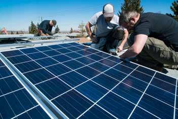
Homeowners in the U.S. see the value in switching to solar and they also see the value in switching at the right time – during a roof replacement. Standard roofs and solar panels have similar lifetimes of 20-30 years, which means installing them together presents a cost-saving solution for homeowners.
Customers in need of a new roof are often shown how to fund a new roof and solar through long term financing. Homeowners are provided the option of redirecting the exact amount they are paying each month to their utility provider for electricity, towards instead investing into a solar panel system that they will eventually own. The options then equate to either “renting or owning” their electricity production.
Financing the solar system is an important factor to consider and, as interest rates climb, lenders are extending solar system loan terms to 25 and 30 years, which may still provide for a cost effective long term advantage compared to paying a utility provider and receiving no ownership in the utility. In short, home owners are going to pay for electricity regardless, so paying a long term loan with the benefit of ownership
30 FLORIDA ROOFING | November 2022

Visit One of Our Locations for the Southeast’s Largest Selection of Roofing Materials and Equipment Roofing Tools Fasteners Drains & Parts Caulking & Sealants Safety Products & Apparel And More! www.crssupply.com 800-874-6152 We have Generators, Tarps and Fasteners in stock at all locations
is almost always going to outweigh the option of “rent ing” electricity production with nothing to show for it after 25 or 30 years.
Solar Companies Can Benefit from Partnerships with Roofing Contractors
While many homes are ready for solar installation, some will require a new roof before solar installation is possible. Solar companies are more likely to convert these customers if they can offer an all-in-one solution or a team approach.
Without a partnership with a roofing company, a so lar installation company must ask customers to search for, vet and choose their own reliable roofing con tractor. Customers don’t want the hassle of doing the extra work required to replace their roof, so if the solar company can offer everything their customer needs to get started, they’re more likely to sell a solar system.
Staffing Challenges are not Unique to Roofing Contractors
The solar industry is expanding at a rapid pace, cre ating millions of jobs for Americans. But these jobs aren’t always filled quickly. It’s a common issue for solar installation companies to run low on staff.
A partnership with a roofing company can po tentially provide a solar company with the staffing support needed to complete an installation. While roofers can’t handle every aspect of solar installation, they can install the framing that the solar panels are attached to.
Roofing Companies Benefit from Partnering with the Solar Industry
The Solar Energy Industries Association (SEIA) pre dicts that in the next ten years, the United States will increase its amount of solar capacity by over 350 percent. The U.S. currently possesses 131 gigawatts (GW) of solar energy and plans to install 480 GW of new solar capacity in the coming decade.
The 131 GW of solar in the U.S. are powered by over 3.5 million solar energy systems, which means Americans can expect to see 13 million more solar
energy systems arise in just ten years – that’s over 1 million each year.
By the end of 2020, 2.7 million solar energy sys tems were residential PV solar energy systems, which means most solar energy comes from panels on residential homes rather than solar farms. A strong desire to avoid land use pushes solar companies to pursue solar roofing, which further decreases the environmental impact of solar and many of these new solar systems will require American homeowners to consent to solar installation.
Some states anticipate solar panels becoming a requirement for new home construction. When this happens, roofing contractors already partnered with solar panel companies will reap the benefits of this partnership by appealing to contractors building new homes.

Many Roofers Already Offer Solar Installation
Solar energy has seen immense success across the U.S., especially in states that receive plenty of sunlight and possess supportive infrastructures for solar devel opment, such as California, Texas and Florida. Roofing contractors in Florida are especially poised to benefit from the nation’s adoption of solar.
Throughout the next ten years, as the solar indus try makes major pushes for growth, the demand for solar and roofing installation services as an all-in-one package will increase and businesses with established partnerships will benefit the most from this increase in demand.
As the U.S. moves forward with technological advancements and the widespread popularity of solar, roofers that don’t offer solar installation or replace ment may fail to meet the needs of their consumers, especially if solar panels become a mandatory require ment for new builds in their area.
Roofing contractors must meet the need for solar installation to survive in the changing market. Like any business owner, roofing contractors across the nation will benefit from taking notice of changes in the mar ket and adapting accordingly for long-term success.
In the U.S., there are over 10,000 solar energy businesses and roughly 80,000 roofing contractors. Although the number of solar energy businesses is on the rise, the select roofing businesses that have already chosen to establish a connection with a solar provider have already experienced the beneficial side effects of the growing solar industry. For those who haven’t already partnered with a solar sales and instal lation company, perhaps now is the time.
FRM
John Fay and Becca Choi of Infinity Solar in Tampa. Contact Infinity Solar to find a local solar provider in all 67 counties in Florida. For information, visit: www.infinitysolarnow.com/contact/.
32 FLORIDA ROOFING | November 2022
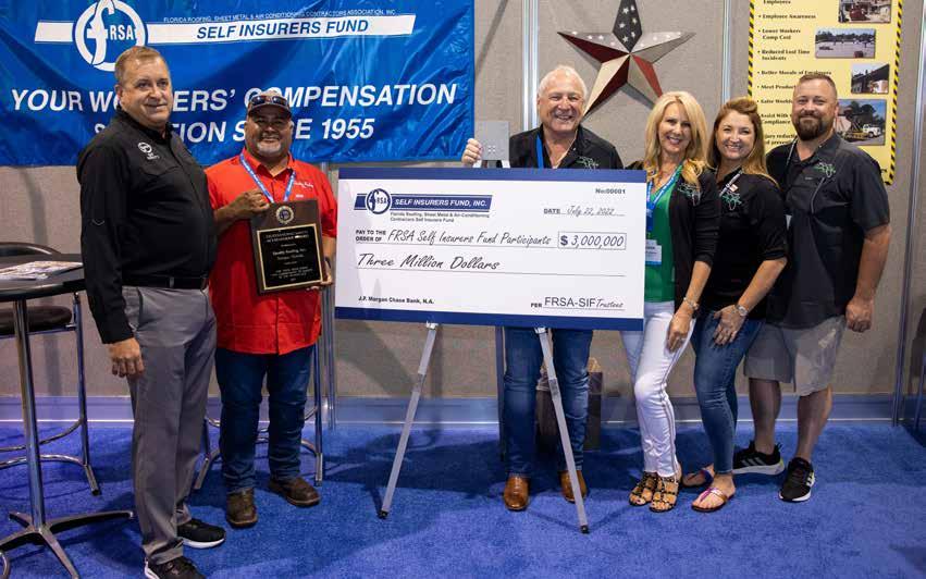
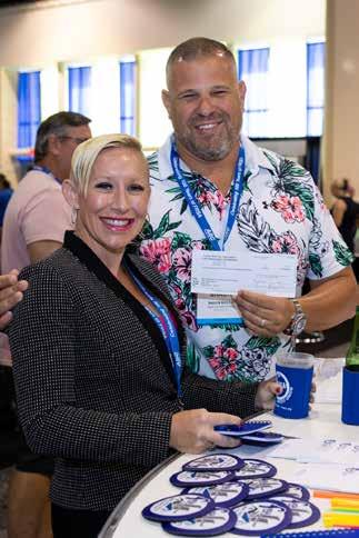
Everyone pays the same workers' comp rate, but does your workers' comp insurance carrier provide you with the potential for a yearly dividend for operating safely? If not, you need to consider the FRSA Self Insurers Fund. These members received their share of $3 million during FRSA's Convention.
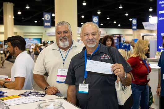
For more information about joining the Self Insurers Fund, contact Alexis at 800-767-3772 ext. 206 or by email: alexis@frsasif.com
Financial Management for Your Roofing Business, Part Two
Last month, in part one of my article, Financial Management for Your Roofing Business, we focused on financial management as a whole and what makes the roofing and construction industry financial man agement unique to other sectors of businesses.
Roofing companies are different from most other companies. Because of this, the principles of finan cial management applied in other businesses must be modified for roofing companies or they will not function well. Our industry has specific challenges and problems not faced by other sectors. In this article, we will explain the four areas of responsibility in financial management.
Accounting for Financial Resources
As a financial manager, you are responsible for track ing (accounting for) how the company’s financial resources are used, which include:
■ Project and general overhead costs are accurately tracked through the accounting system.
■ Ensure that proper construction accounting methods and systems have been set up and are functioning correctly.
■ Project cost completions for the individual proj ects and ensure that unbilled committed costs – costs the company has committed to pay but has not received a bill for – are included in these projections.
■ Determine whether the individual projects are over or underbilled.
■ Prepare all required financial statements.
■ Review the financial statements to ensure that the company’s financial structure is aligned with industry standards.
Because of the unique characteristics of construc tion and roofing companies, some key differences exist between our industry’s accounting systems and financial statements for other industries. Before you can understand how to read a roofing company’s financial statements or how these costs are tracked and managed, the financial manager must under stand how construction accounting systems operate. Financial managers must review the accounting re ports for errors, including improperly billed or omitted costs, to ensure that the necessary corrections are made.
Analysis of financial statements will help the financial manager and the owner identify prob lems before they become a crisis. A crisis, such as realizing that your compa ny will not be able to pay its bills in the upcoming months, can be life-threat ening to your company.
Managing Costs and Profits
Financial managers are responsible for managing the company’s costs and earning a profit for the stakeholders. They rely heavily on the reports from the accounting system to manage these costs. Managing the company’s expenses and profits include the following duties:
■ Controlling project costs.
■ Monitoring project and company profitability.
■ Setting labor burden markups.
■ Developing and tracking general overhead budgets.
■ Determining the minimum profit margin for use in estimating.
■ Analyzing your company’s profitability and making the necessary changes to improve profitability.
■ Monitoring the profitability of different custom ers and recommending modifications required to improve profitability.
Financial managers need specific skills to deter mine project success and to identify problem areas. They then can provide accurate information to the Project Manager, Superintendent or other stakehold ers who need to know how their projects are doing.
Managing Cash Flow
Many profitable roofing companies fail because they run out of cash and cannot pay their bills. Managing the cash flow of your company is essential and is the financial manager’s responsibility. These duties include:
■ Matching in-house labor and subcontractors to the cash available for use on projects.
34 FLORIDA ROOFING | November 2022
COTNEY CONSULTING GROUP
John Kenney, CPRC, CEO, Cotney Consulting Group
■ Ensuring your company has sufficient cash to take on additional projects.

■ Preparing income tax projections for your company.
■ Preparing and updating cash flow projections for your company.
■ Arranging for the financing needs of your company.
Cash is the lifeblood of your company and cash flow projections ensure your company has sufficient money for the upcoming year. Cash flow projections are prepared by projecting the revenues and expenses for your company by combining the cash flows from individual projects. You then combine the projected revenues, project costs, general and overhead admin istrative budget and forecasted income taxes with your available money to determine the company’s cash needs. If you find insufficient funds, you will have time to arrange the necessary financing to provide the required cash needs.
Choosing Financial Alternatives
Financial managers are also responsible for selecting financial option alternatives. These decisions include:
■ Selecting which equipment to purchase and when.
■ Deciding to invest your company’s limited resources in which area of your business.
Many financial tools are available to analyze the alternatives quantitatively. It is difficult to determine which option is best without some measurable meth od. Understanding these skills is necessary for any financial manager deciding where to invest limited capital. Income taxes can also influence the choice of financial decisions. Income taxes can make different
financial alternatives preferable and should be part of your formula when weighing financial alternatives.
To sum it up, a roofing company is a risky ven ture. Every year, many roofing companies go out of business. Operating a successful roofing company re quires a specialized set of financial management skills because of the unique nature of our industry. Unlike other industries, the roofing industry faces several challenges, including:
■ Projects are unique and often one of a kind.
■ Projects are different and located in various geo graphical locations.
■ Handling progress payments and retainage.
■ Projects use in-house labor or subcontractors to complete.

This article is intended to provide the information necessary to develop the financial management skills you require to become a successful roofing company owner or manager.
FRM
John Kenney, CPRC has over 45 years of experience in the roofing industry. He started his career by work ing as a roofing apprentice at a family business in the Northeast and worked his way up to operating multiple Top 100 Roofing Contractors. As CEO, John is intimately familiar with all aspects of roofing pro duction, estimating and operations. During his tenure in the industry, John ran business units associated with delivering excellent workmanship and unparal leled customer service while ensuring his company’s strong net profits before joining Cotney Consulting Group. If you would like any further information on this or another subject, you can contact John at jkenney@cotneyconsulting.com.
www.floridaroof.com | FLORIDA ROOFING 35
Growing. Expanding. Remaining True to Quality & Service. integritymetalsfl.com772-584-2654
Giving Back
FRSA Members Giving Back to the Community

Polyglass U.S.A Supports the Relief Effort in Ukraine
Polyglass U.S.A., Inc., a leading manufacturer of roofing and below-grade waterproofing systems, is committed to giving back to local and international communities and is proud to partner with and support global organizations providing emergency aid in times of crisis.
Following the Russian invasion of Ukraine, the Polyglass family, CEO and Executive Leadership Team felt the need to support the war relief effort and chose to partner with Global Empowerment Mission (GEM), a U.S.-based non-profit organization founded in 2011 as a first responder to global disasters.
Over the past six months, GEM and local NPO partners have delivered much-needed emergency aid inside Ukraine, including the regular distribution of food and care packages and financial assistance
for short-term incidentals and temporary housing to Ukrainian refugees, fighters and their families in over 108 areas.
With the help of donor partners, GEM has repaired and reopened six schools. In addition, GEM has helped extract and relocate refugees, providing accommoda tion to women and children crossing the border from Ukraine into Poland.
GEM’s Founder, Michael Capponi, currently lives in Kyiv and oversees operations. “We try to solve com plex problems with innovative solutions,” he shared in a video on the repair and reopening of a kindergarten in Bucha in Kyiv Oblast. “We have to bring continuous resources,” he urged, emphasizing the critical aid still needed to ensure Ukrainians in war-torn regions are not forced back into refugee status from a lack of safe housing.
A Giving Back donation page on the Polyglass website enabled Polyglass employees, families and friends to raise $10,000 towards GEM’s relief work within four months. Polyglass U.S.A. matched this donation and in September, Polyglass team members trav eled to the GEM headquarters in Miami to present $20,000 to GEM leaders and tour the NPO’s warehouse facility.
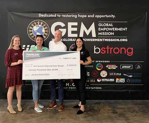 FRM
FRM
FRSA is proud of the volunteer work completed by members in the industry and would like to share those projects as often as possible. If you have a community service project you’ve completed, please send it to Lisa Pate at lisapate@floridaroof.com.
36 FLORIDA ROOFING | November 2022
THE PREMIER ROOFING AND EXTERIORS EVENT
The 2023 International Roofing Expo® [IRE] puts you at the center of it all — providing unparalleled access to the tools, technologies and resources you need to maximize your roofing success. It’s where new products are launched, great ideas are born and creativity and innovation unite. See the latest trends, source roofing products, meet icons of industry, network and expand your knowledge in the educational conference sessions. Stay on top of the latest news in the industry at roofingexteriors.com

LEARN MORE! theroofingexpo.com OFFICIAL DIGITAL MEDIA BRANDOFFICIAL SHOW PUBLICATIONOFFICIAL SHOW SPONSOR MARCH 7-9, 2023 DALLAS,TX KAY BAILEY HUTCHISON CONVENTION CENTER
Safety Meetings
Kevin Lindley, Safety Consultant, FRSA Self Insurer’s Fund
“Safety meetings are a waste of time and money.”
There, I said it. It is often said that meetings to discuss safety topics are a waste of time, money and resources. Yes, safety meetings by themselves, without intention, application, follow through, rein forcement and, most importantly, comprehension, can be a waste of time.
There are many reasons safety meetings are not producing the desired results. Employees and work ers come to morning meetings with their mind on the tasks at hand; they are not mentally present at the meeting. Amazingly, most field workers do not do well in a classroom setting and have trouble com prehending certain ideas when only discussed – they are hands-on individuals. Language barriers, hunger, distractions in and around the training area, timing of the meeting, poor speaker(s), ill-prepared lessons, non-applicable material, others in the room, etc. are some of the distractions or reasons they are not men tally present.
When approached poorly, safety meetings can be needlessly repetitive, rehashing the same topics in the same way. I can only watch the same episode of a TV show so many times before I stop watching or paying attention to it. We should ask, if the information has been heard several times, then why aren’t the safety practices being adopted in the field?
There is a gap in training to application in the field when it comes to safety practices and that is frustrat ing. Companies talk about safety and employees want to be safe, but we are often training and reinforcing in the wrong fashion. It is frustrating as a trainer to talk about a topic for an hour, only go into the field and observe workers blatantly disregarding what was just reviewed only minutes earlier.
So, how do we “fix” this problem? How does a company break through the barrier and achieve com pliance with safety policies in the field? Wanting to be safe does not make workers safe. Talking about safety occasionally does not make much of an impact. Going into the field and forcing the workers to comply with safety regulations only makes a temporary difference. There is no single missing ingredient for success in this recipe. Training needs to be fully comprehensive, both in language and content. It needs to be delivered in such a fashion that the workers present are able to understand and mimic it in the field. It has to be practi cal; it needs to be uniformly applied and followed. This means management needs to hold workers account able and the other workers need to hold each other accountable.
I was once in an informal OSHA conference in Jacksonville speaking with the current Area Director
for OSHA, Nolan Houser, about fall protection training – a topic all too often discussed with roofing contrac tors in those offices. Nolan asked a contractor about his training program. The contractor proudly present ed the annual sign-in rosters from the past three years for safety trainings held in the office with employees. He explained that the company had gathered all the workers together, had a trainer come into their office who held a one hour discussion with the workers that included a presentation and went on to explain how well-received the meeting was. Workers asked for new fall protection equipment following the meeting and the contractor really believed that the meeting was a huge success.
Nolan patiently listened to the contractor go on about the training session. When the contractor had finished, Nolan asked the contractor how the com pany knew the training was a success. Was there any demonstration, application, follow-up or reinforce ment during or after the training session? Sadly, the company did not have any documentation or confir mation of follow-up (site inspections), no disciplinary action taken against any, not even one employee, for non-compliance in the field (reinforcement). Without this key additional information, the training was invalid. It aided the contractor in a slight reduction of the citation value, but there were clearly deficiencies in the “program” evident by the issues observed by the OSHA Field Compliance Officer, resulting in a citation to the contractor.
So, what can we as roofing contractors learn from this? What can we do better? In reading this, I trust you have already begun to think of ways you can fix your deficiencies to make your training more effective. Please do not let your thought die there; put it into ac tion, write down your notes, send out a memo or mass email, get others on the same page as you and put your thoughts into action. We can do better; we must do better for the sake of our workers.
Safety meetings are not a waste of time, money and resources – but only if they are presented well and are applicable to the people listening. Then they must be effectively reinforced and assessed in the field.
FRM
The FRSA Self Insurer’s Fund (FRSA-SIF) has pro fessional safety consultants throughout the state who are willing to provide SIF members with safety training at no additional cost. To find out if you qual ify for FRSA-SIF membership, please contact us at 800-767-3772, ext. 206, or email alexis@frsasif.com. To learn more about the FRSA Self Insurers Fund, please visit www.frsasif.com.
38 FLORIDA ROOFING | November 2022
When sunny skies aren’t so sunny.
Ultra HT is the premium, high temperature, self-adhering underlayment engineered to take on whatever Mother Nature dishes out. Whether it’s extreme heat, wind-blown rain, or ice and snow, Ultra HT provides complete waterproofing protection.
• High temperature rated up to 250°F
• Tough and durable cross-laminated construction
• Self-seals around roofing fasteners

• Non-slip traction coated top film
Ultra HT is designed for whole roof coverage to protect your project before, during and after the installation of the final roofing system. Peace of mind you and your customer will appreciate. Visit mfmbp.com for a free sample or call 800.882.7663 today.
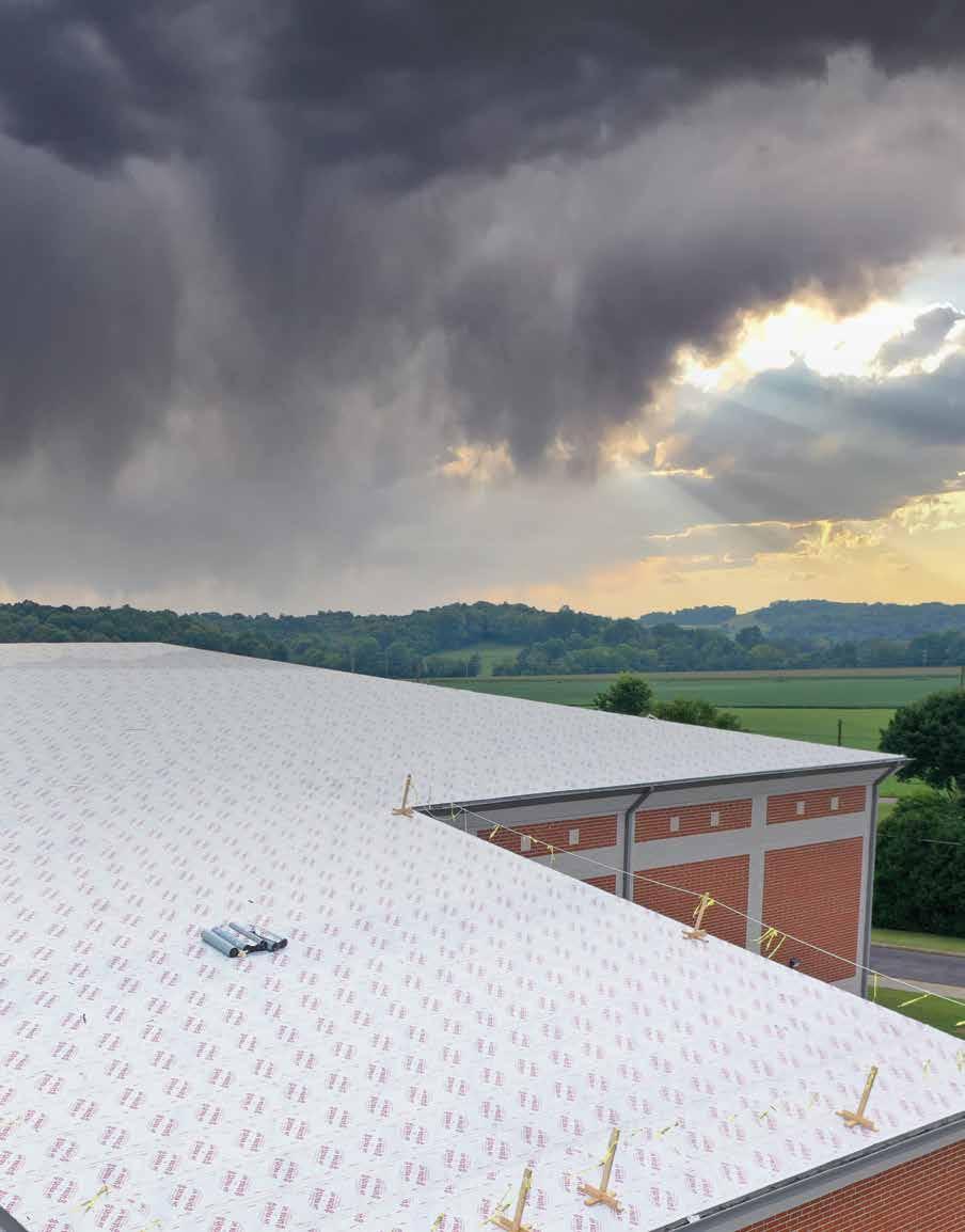
SAVE TIME WITH EVERY ORDER
Beacon PRO+ connects with your local Beacon branch enabling you to order all your building materials online.
Jacksonville, FL 32209 (904) 503-9400
Jacksonville, FL 32209 (904) 503-9400
Tallahassee, FL 32304 (850) 574-7600
Tallahassee, FL 32304 (850) 574-7600
Odessa, FL 33556 (813) 749-5354
Odessa, FL 33556 (813) 749-5354
Orlando, FL 32804 (407) 291-7244
Orlando, FL 32804 (407) 291-7244
Tampa, FL 33619 (813) 740-8790
Tampa, FL 33619 (813) 740-8790
Fort Myers, FL 33916 (239) 935-5077
Fort Myers, FL 33916 (239) 935-5077
Deerfield Beach, FL 33442 (954) 969-8000
Deerfield Beach, FL 33442 (954) 969-8000
Miami, FL 33142 (305) 635-7177
Miami, FL 33142 (305) 635-7177
Orlando, FL 32809 (407) 367-6246
Orlando, FL 32809 (407) 367-6246
Ocala, FL 34474 (352) 622-3933
Ocala, FL 34474 (352) 622-3933
Melbourne, FL 32904 (321) 369-7892
Melbourne, FL 32904 (321) 369-7892
Ormond Beach, FL 32174 (386) 301-4471
Ormond Beach, FL 32174 (386) 301-4471
Palmetto, FL 34221 (941) 722-6800
Palmetto, FL 34221 (941) 722-6800
Leesburg, FL 34748 (352) 818-6120
Leesburg, FL 34748 (352) 818-6120
Orlando, FL 32804 (407) 859-9997
Orlando, FL 32804 (407) 859-9997
Winter Haven, FL 33880 (863) 293-1555
Winter Haven, FL 33880 (863) 293-1555
St. Petersburg, FL 33716 (727) 565-4630
St. Petersburg, FL 33716 (727) 565-4630
Sarasota, FL 34243 (941) 203-6320
Sarasota, FL 34243 (941) 203-6320
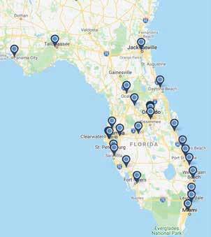
Fort Pierce, FL 34982 (772) 466-3461
Fort Pierce, FL 34982 (772) 466-3461
Stuart, FL 34997 (772) 223-8881
Stuart, FL 34997 (772) 223-8881
Vero Beach, FL 32960 (772) 778-0549
Vero Beach, FL 32960 (772) 778-0549
Orlando, FL 32810 (321) 442-0061
Orlando, FL 32810 (321) 442-0061
Fort Lauderdale, FL 33315 (954) 525-1158
Fort Lauderdale, FL 33315 (954) 525-1158
Riviera Beach, FL 33407 (561) 863-9899
Riviera Beach, FL 33407 (561) 863-9899
Clearwater, FL 33762 (727) 573-6075
Clearwater, FL 33762 (727) 573-6075
Panama City, FL 32401 (850) 763-0851
Panama City, FL 32401 (850) 763-0851
North Port, FL 34289
North Port, FL 34289 NOW OPEN!!!
Go to BECN.com to sign up or download the app.
Go to BECN.com to sign
NOW OPEN!!! 24/7 online access to your account Place and track orders SAVE TIME WITH EVERY ORDER Beacon PRO+ connects with your local Beacon branch enabling you to order all your building materials online.
up or download the app.
24/7 online access to your account Place and track orders