Design V500 Table 4. Data for Tapped Hole in Valve Shaft SHAFT DIAMETERS VALVE SIZE, INCHES
0.50
0.50
12.7
12.7
10-24
0.62
0.62
15.9
15.9
1/4-20
2
0.62
0.62
15.9
12.7
10-24
1.00
1.00
25.4
15.9
3/8-16
1.00
0.75
25.4
25.4
5/16-18
1.25
1.25
31.8
19.1
3/8-16
1.50
1.50
38.1
38.1
1/2-13
1.50
1.25
38.1
31.8
3/8-16
1.50
1.50
38.1
38.1
1/2-13
6 8
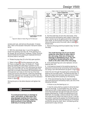
screws and nuts, and remove the actuator. If necessary, refer to the actuator instruction manual for assistance. 3. With the valve body (key 1) out of the pipeline, loosen the packing nuts (key 16). If the packing is to be reused, do not remove it. However, Fisher Controls recommends that the packing be replaced whenever the drive shaft is removed. 4. Rotate the plug (key 2) to the fully open position. 5. Refer to figure 9. Find the expansion pin (key 9).There is a taper pin (key 10) inside of it. These parts are holding the valve plug in position on the shaft. Find the larger hole in the valve plug hub where these pins enter the hub. On the opposite side of the plug hub is a smaller hole where the chamfered end of the expansion pin rests on the inner lip of the hole. Using a pin punch and hammer, strike the chamfered end of the expansion pin through the smaller hole. Remove both pins from the valve plug hub in the direction shown in figure 9. Driving the pins in the other direction will tighten the pins.
THREAD SIZE, UNC
1
4
Figure 9. Detail of Valve Plug for Pin Removal
Through At Spline Body End mm
1-1/2
3
A3307-1 / IL
Through At Spline Body End Inches
6. Pull the shaft (key 3) from the valve body. If the shaft cannot be removed by hand, attach a slide hammer or similar tool to the spline end of the valve shaft. Each shaft, on the 6 and 8 inch sizes, has a tapped hole at the spline end of the shaft; refer to table 4 for thread sizes. 7. Remove the plug and thrust washer (key 12) from the body. Note Two shaft bearings (key 6) are located inside the valve body on either side of the valve plug. Only one of these two bearings is identified by key 6. The other bearing is located along the valve shaft on the other side of the valve plug. 8. If the shaft bearings are to be replaced, remove packing (key 13). 9. If the bearing closest to the packing requires replacement and cannot be removed by hand, press it out using a ram with dimensions as given in figure 10. Insert the ram through the packing box and press the bearing into the body cavity. The bearing stop (key 7) does not need to be removed; take care not to move the bearing stop when pressing out the bearing. 10. If the second bearing (key 6) requires replacement and cannot be removed by hand, use one of the following methods: R Knock or pry the bearing out, or
WARNING To avoid personal injury or damage to tools, valve parts, or other items and plug damage resulting from the valve plug falling from the body, support the plug to prevent it from falling as the shaft (key 3) is being removed.
R Use the valve shaft as a piston to drive the bearing from the body. To accomplish this, first, fill the bearing bore with a heavy grease and then insert the end of the shaft back through the body and into the grease-filled bearing. Protect the splined end of the shaft with, for example, a block of wood; then strike the protected end. When the shaft is struck, it will act as a piston, pushing the grease into the bearing bore. The grease will then force the bearing out of the bore and farther along the shaft. Soon, the bearing will be positioned for easy removal.
13