S203 Series
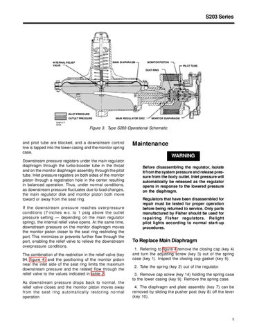
MONITOR PISTON
MAIN DIAPHRAGM
INTERNAL RELIEF VALVE
PILOT TUBE SEAT RING
INLET PRESSURE OUTLET PRESSURE
MAIN REGULATOR DISC
MONITOR DIAPHRAGM
50A9737-F A4195
Figure 3. Type S203 Operational Schematic
and pitot tube are blocked, and a downstream control line is tapped into the lower casing and the monitor spring case. Downstream pressure registers under the main regulator diaphragm through the turbo-booster tube in the throat and on the monitor diaphragm assembly through the pitot tube. Inlet pressure registers on both sides of the monitor piston through a registration hole in the center resulting in balanced operation. Thus, under normal conditions, as downstream pressure fluctuates due to load changes, the main regulator disk and monitor piston both move toward or away from the seat ring. If the downstream pressure reaches overpressure conditions (7-inches w.c. to 1 psig above the outlet pressure setting — depending on the main regulator spring), the internal relief valve opens. At the same time, downstream pressure on the monitor diaphragm moves the monitor piston closer to the seat ring restricting the port. This minimizes or prevents further flow through the port, enabling the relief valve to relieve the downstream overpressure conditions. The combination of the restriction in the relief valve (key 94, figure 4) and the positioning of the monitor piston near the inlet side of the seat ring limits the maximum downstream pressure and the related flow through the relief valve to the values indicated in table 2. As downstream pressure drops back to normal, the relief valve closes and the monitor piston moves away from the seat ring automatically restoring normal operation.
Maintenance WARNING Before disassembling the regulator, isolate it from the system pressure and release pressure from the body outlet. Inlet pressure will automatically be released as the regulator opens in response to the lowered pressure on the diaphragm. Regulators that have been disassembled for repair must be tested for proper operation before being returned to service. Only parts manufactured by Fisher should be used for repairing Fisher regulators. Relight pilot lights according to normal start-up procedures.
To Replace Main Diaphragm 1. Referring to figure 4 remove the closing cap (key 4) and turn the adjusting screw (key 3) out of the spring case (key 1). Inspect the closing cap gasket (key 5). 2. Take the spring (key 2) out of the regulator. 3. Remove cap screw (key 14) holding the spring case to the lower casing (key 9). Remove the spring case. 4. The diaphragm and plate assembly (key 7) can be removed by sliding the pusher post (key 8) off the lever (key 10).
5