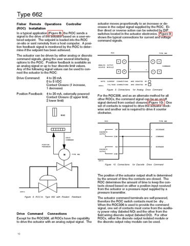
Type 662 Fisher Remote Operations Controller (ROC) Installation In a typical application (Figure 8), the ROC sends a signal to the drive of the actuator based on a user-entered setpoint. The setpoint is loaded into the ROC on-site or sent remotely from a host computer. A position feedback signal is monitored by the ROC to determine if the setpoint has been achieved. The actuator can be driven by either analog or discrete command signals, giving the user several interfacing options to the ROC. Position feedback is available as an analog signal or up to four discrete limit values. Any of the following signal values can be used to connect the actuator to the ROC: Drive Command:
4 to 20 mA 0 to 5 VDC Contact Closure (1 increase, 1 decrease)
Position Feedback:
4 to 20 mA, externally powered Contact Closure (2 upper limit, 2 lower limit)
ROC
actuator moves proportionally to an increase or decrease in the output signal supplied by the ROC. Either direct or reverse action can be selected by DIP switches located in the actuator electronics. Figure 9 shows the typical connections for current and voltage command signals.
ROC
TYPE 662
C ANALOG SOURCE
3
C
6
OUTPUT MODULE
COMMAND + A
NOTE: CURRENT A6830/IL
+
B
4
CONNECTIONS
ARE DENOTED
BY
VOL TAGE CONNECTIONS
ARE DENOTED
BY
Figure 9. Connections
5
for Analog Drive Command
For the ROC306, and as an alternate method for all other ROCs, the command signal can be an on/off signal derived from contact closures (Figure 10). One set of contacts is required to drive the actuator clockwise and another set is required to drive it counter clockwise. ROC
TYPE 662
NO
1
DECREASE
COM
3
COMMAND
NO
2
INCREASE
DISCRETE OUTPUT DRIVE COMMAND POSITION FEEDBACK DISCRETE OUTPUT
M
COM
TYPE 662
A6831/IL
Figure 10. Connections
Type 662 with Position
Feedback
Drive Command Connections Except for the ROC306, all ROCs have the capability to drive the actuator with an analog output signal. The
10
Drive Command
The position of the actuator output shaft is determined by the amount of time the contacts are closed. The ROC determines the amount of time to keep the contacts closed based on either a position input received from the actuator or a pressure input supplied by a pressure transmitter.
A6829/IL
Figure 8. ROC-to
for Discrete
The actuator command terminals are self-powered, therefore the ROC switch contacts must be �dry�. When the ROC306 is used to provide the command signal, one set of contacts must come from the auxiliary power relay (labeled NO) and the other from the field wiring discrete output (labeled DO). For other ROCs, either the discrete output isolated module or the discrete output relay module can be used.