9 minute read
A step up


Calvin Silver and Scott Hansen, GeoCorr, USA, explain the results from a push for ‘smarter’ caliper technology by industry-leading transmission companies that propelled the steps to better data.
Geometry inspections continue to lead the way when initiating your baseline integrity assessments. While thousands of runs are conducted over the global market, evolving technology continues to drive this industry forward. While we become smarter at earlier stages within the pipeline’s life, this helps protect these assets, address anomalies, and improve integrity decision-making.
GeoCorr’s new TCII HiRes Caliper with IMU is a step up in your tool kit, whether at pre-commissioning of a pipeline or for geohazard and dent strain assessments on in-service lines.
System design and architecture Tackling the new high-resolution market, the TCII HiRes caliper system was designed to accommodate two caliper arms per dia. in. (Figure 1). Every tool diameter, 3 in. through 56 in. would see this new standard. The inline inspection system would serve to meet the rugged expectations of new construction applications, while setting a new standard with sensitivity and detection by employing this new caliper sensor technology.
The digital sensor technology has reduced the signalto-noise ratio by a factor of 10, and widened the sensor’s usable range to 100% of the available mechanical travel. This has allowed for exceptional sizing accuracy and increased confidence in low percentage features within the 0 - 2% OD range. In conjunction with the geometry sensor technology, the odometer system can be linearly sampled at user-selected 1 - 4 mm based on application requirements. With resolution more than doubling on direct wall caliper sensors, and the linear sampling more than doubling as well, confidence levels and accuracies are at an all-time high.
With these expanded capabilities, the TCII has been tackling a wide range of applications: ) Early detection and identification of anomalies and mechanical damage occurring during construction.
) Dent strain analysis where better data capture on geometry/ caliper data provides a more accurate evaluation of your
ASME B31.8 strain results and anomaly shape.
) Dual and multi-diameter applications – previous Dual Dia.
Technology had sensor limitations. A compromise was typically given to the larger diameter pipe with regards to sensor measurement, coverage, and accuracy. Major improvements to measurement linearity throughout both pipe diameters have been achieved in dual-diameter applications with up to a 6 in. difference in pipeline OD.
Proof of concept work was executed through 2020 with in-house development and testing split between GeoCorr’s production headquarters and engineering team. During system validation, extensive calibration procedures were carried out along with in-pipe testing. Using the high-resolution digital
sensors, multiple samples are taken during calibration for each point, resulting in clearer data acquisition and more accurate subsequent pipe measurement. Across the many arms and steps of the calibration graph, graphs present as nearly linear throughout the mechanical range (Figure 2). The implications of this are twofold: ) Wide swings in diameter (whether due to extreme restriction or multiple diameter pipelines) do not compromise the quality of the sensor reading.
) This then allows for quick benchmarking and validation of calibrations where the effects of human error are greatly reduced because the easy recognition of invalid data points during infield calibrations or the standard tool preparation process.
Pipe-based measurements were performed for wall thickness calibrations. The high sensor density combined with the sensor has made a big impact on data analysis. This has allowed for a simpler interpretation of the slightest changes in internal diameter discrepancies and changes in wall thickness.
With the design intent of exceeding 1 mm of detection accuracy on wall thickness, validation has been performed on the sensors down to the finest calibration block with a thickness of 0.25 mm or just under 0.01 inches. This would be the equivalent of a 0.028% dent in a 36 in. pipe. Consistent measurement of the 0.25 mm calibration blocks was achieved for all arms with repetition and repeatability (Figure 6). These tests provided an observation of baseline sensor noise within the system, further demonstrating that electronic noise would not impact measurements as small as a quarter of a millimetre. Being able to detect changes in the pipe wall with TCII HiRes Caliper at a thickness less than a credit card should provide smarter information to pipeline integrity decision-makers prioritising threats to their assets.
A novel approach to high-resolution validation As of late 2021 in-field testing was completed on the TCII HiRes system by GeoCorr’s team that has been specialising in caliper inspections for over 16 years. Several inspections pushed through compressed air have been performed across 20 - 42 in. pipelines in the precommissioning phase. With a 100% first-run success rate during its deployment in multiple new construction applications, the TCII HiRes has yielded a few real-world observations.
Validation of in-run measurement at precommissioning has traditionally been performed based on the industry-standard dig specifications of 2% dents and 5% ovalities. While some end users have endeavoured to excavate 1% features for both anomaly types,

Figure 1. Rear view of GeoCorr’s 36 in. TCII HiRes Caliper Tool with 72 channels.
Figure 2. 36 in. Tool Calibration: each arm has an approximately flat profile across a full 30 cm of mechanical range.
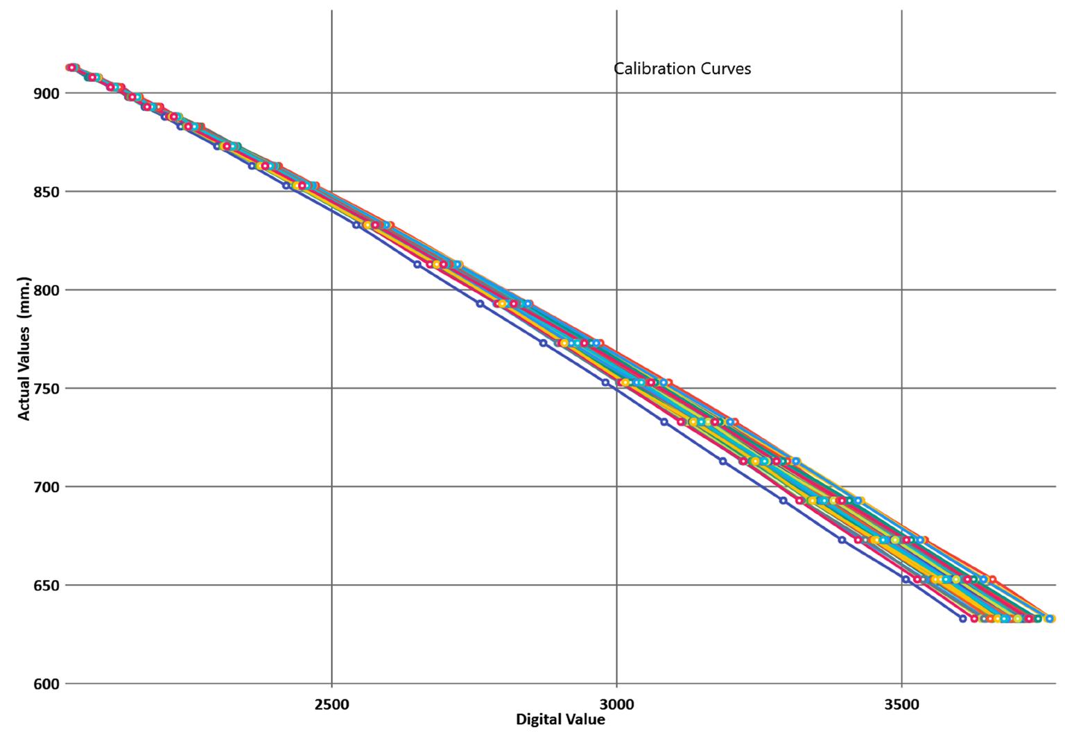

Figure 3. Dent A: Channel view of ~2.56 mm dent profile (0.28% against baseline) adjacent to spiral weld signature for comparison. Blue dotted lines denote dent baseline zone and the white arrow signifies the spiral weld.
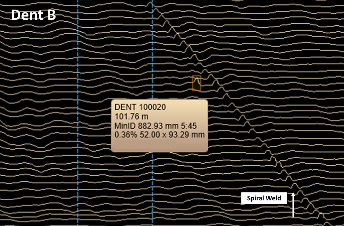
Figure 4. Dent B: Channel view of ~3.29 mm dent profile (0.36% against baseline) adjacent to spiral weld signature for comparison. Blue dotted lines denote dent baseline zone and the white arrow signifies the spiral weld.

Figure 5. Dent C: Channel view of ~4.11 mm dent profile (0.45% against baseline) adjacent to spiral weld signature for comparison. Blue dotted lines denote dent baseline zone and the white arrow signifies the spiral weld. finding ways to validate a high-resolution tool against very small features in-field has been challenging as they are not typically candidates for excavation or cut-out.
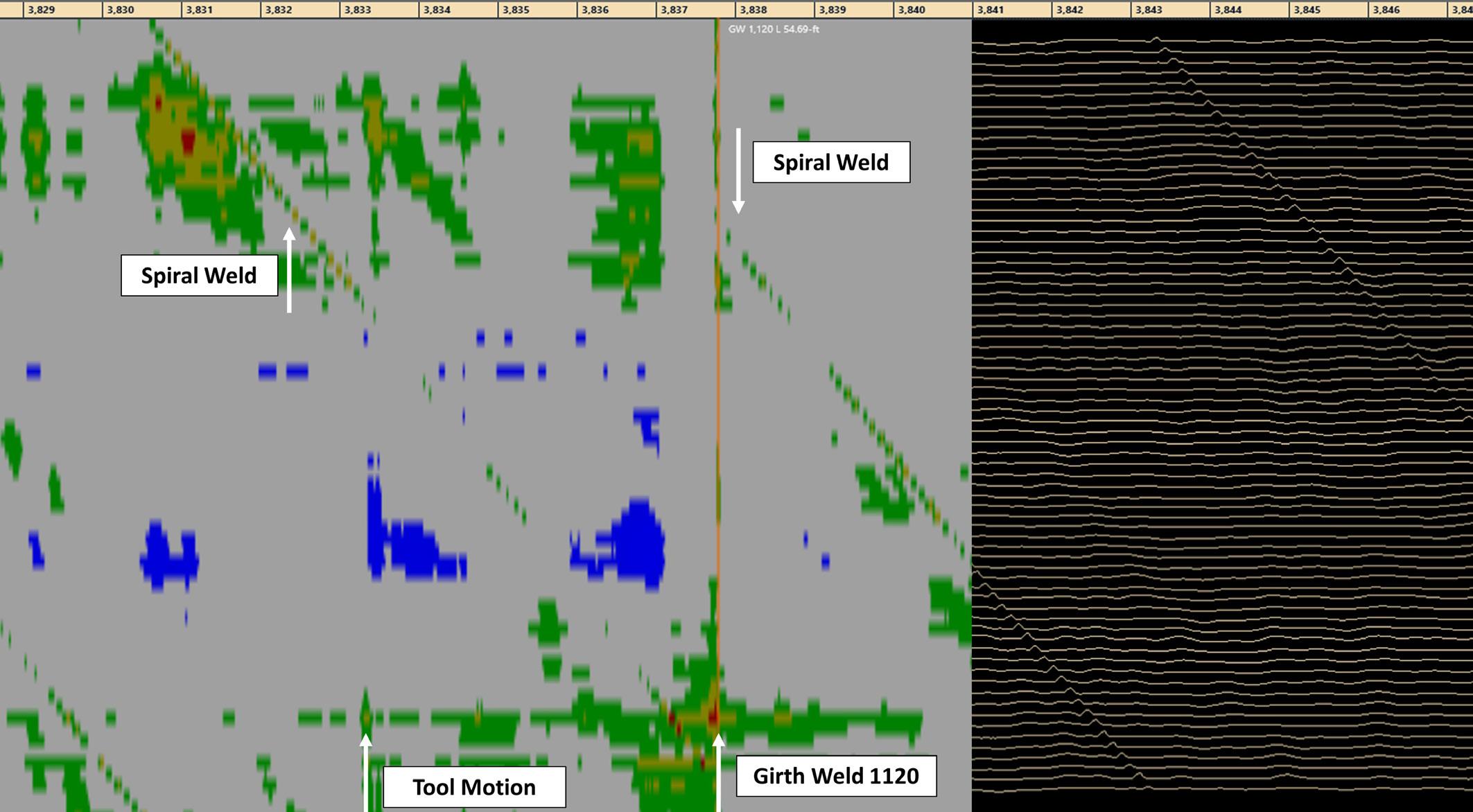
Sizing the height of a spiral weld for a 36 in. spiral welded pipe provided a consistent expression for the extent of the entire line, measuring 2 - 4 mm across all sensors and on all joints (Figure 7). While the sizing of the spiral weld is not a classical diagnostic of an effective ILI tool, it is extremely useful for proving the consistency of a high-resolution caliper. ‘Spiral weld reinforcement height’ is a parameter with an API-specified tolerance during manufacturing. The spec states the weld must be less than or equal to 4.76 mm for wall thicknesses greater than 0.500 inches. A standard-length joint of spiral weld pipe will allow each sensor on the tool to pass a spiral well 6 - 8 times. On a 3 mile line, this provides for over 2000 sensor verifications for each arm.
Identification of low percentage ID reductions (dents, debris, mill anomaly, etc.) in the spiral welded pipe allows for a comparison of the anomaly to the consistently milled and measured weld feature. Sizing anomalies adjacent to the weld signatures showcase the reliability of the TCII HiRes sensing technology, even while running in the particularly challenging new construction environment, while being pushed with compressed air in a low-pressure setting. Figures 3 - 5 present a collection of three different low percentage expressions near the previously mentioned spiral welds.
All three anomalies reside on the bottom of the pipe, so while these certainly resemble ID reductions, differentiating these anomalies as dent, debris, or mill defects is another task. They have been classified as dents for this study. The anomalies presented vary in magnitude and when compared to the spiral weld signature present as Dent A being smaller than the size of the weld, Dent B being similar in size, and Dent C being greater in size. Note that each of the figures has a baseline zone (blue dotted lines) of measurement adjacent to the feature which encompasses some vibration and provides an average ‘nominal’ reading for the anomaly. Using the information previously gathered on the spiral weld features, the anomalies size appropriately, by comparison, suggesting valid readings for all the expressions. Note that the largest anomaly showcased here is 0.45% and 0.16 in. and is distinctly observed across two caliper channels on this 36 in. inspection.
Through inspections in ERW pipes, there have been other observations of low percentage anomalies across multiple caliper channels. There has also been detected expression of long seam welds, suggesting that identification of long seams caliper only technology is possible. Long seam expression is dependent on a few factors; both the manufacturing process, and run parameters seem to vary interpretation capabilities. However, this case study highlights successful detection through the aided use of heat mapping software views traditionally used by MFL analysts, which assists in providing a clearer interpretation of the detection.
Evaluation and possibilities The potential of the GeoCorr’s TCII HiRes Caliper system provides elevated data quality and detection and
opportunities to further push forward with other technology to fulfil multiple integrity needs, whether it be IMU (for mapping, bend strain, or geohazard), debris mapping, as a more informative go-no-go, or as an aid of detection of small illegal taps or long seam.
This progress demonstrates a considerable step up in terms of data collection for a caliper technology, meeting the most stringent end user requirements under some of the toughest conditions. In-field testing has resulted in consistently verifying this specification while providing a high level of reliability which, historically, has been challenging while deploying recently developed technology.
Acknowledgments The authors would like to thank their committed customers for continuing to acknowledge the importance of developing new standards to push the growth of pipeline technology, and the dedicated Engineering, Operations, Software, and Analysis personnel at GeoCorr for their contributions to these advancements.
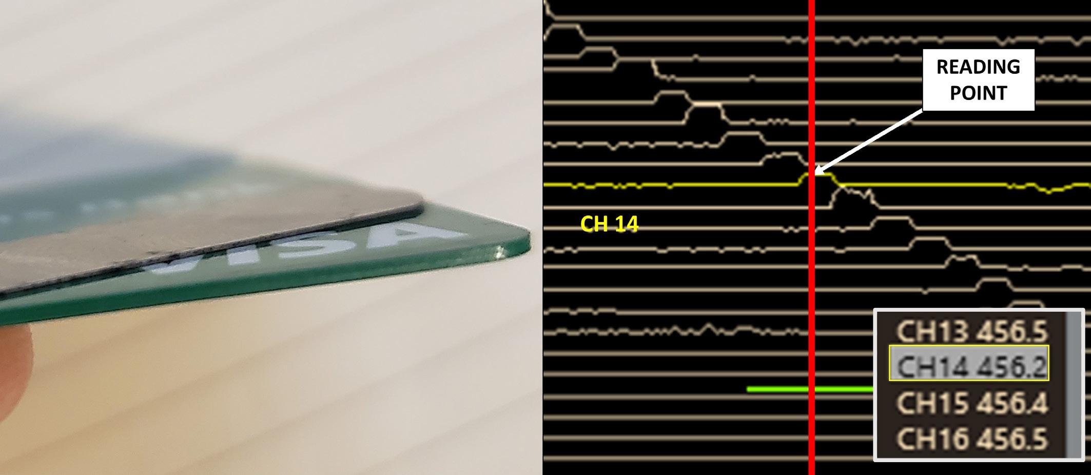
Figure 6. The use of the 0.25 mm feeler gauge (compared to standard credit card on left) provides consistent measurement above baseline for all arms. Sensor noise does not impact baseline. Channel 14 with measurement inset in millimeters.
Figure 7. Heat map view (split with channel) of spiral welded pipe around girth weld #1120. The spiral weld consistently measures 2 - 4 mm across all channels. Upstream of the girth weld there is tool motion where the drive cup impacts the weld.