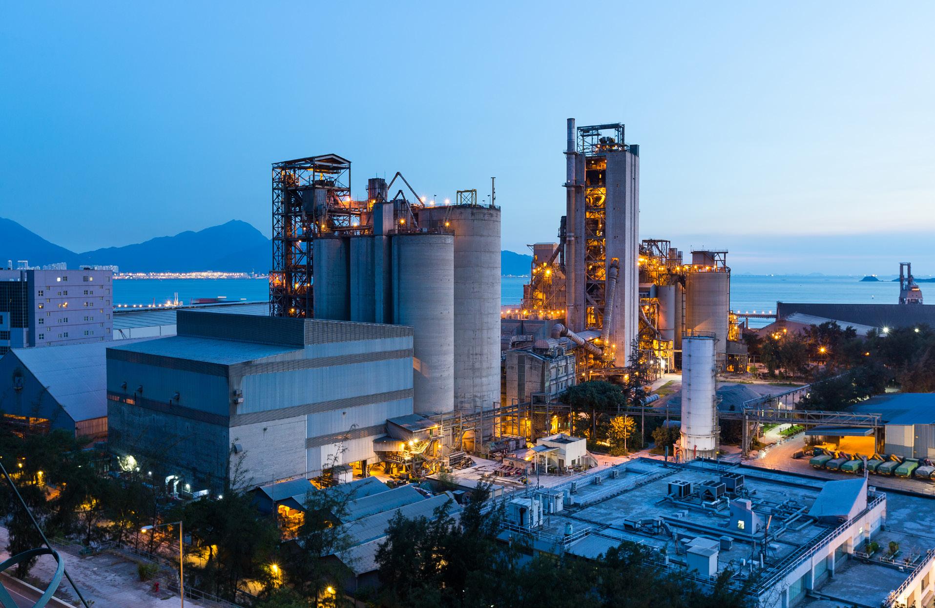
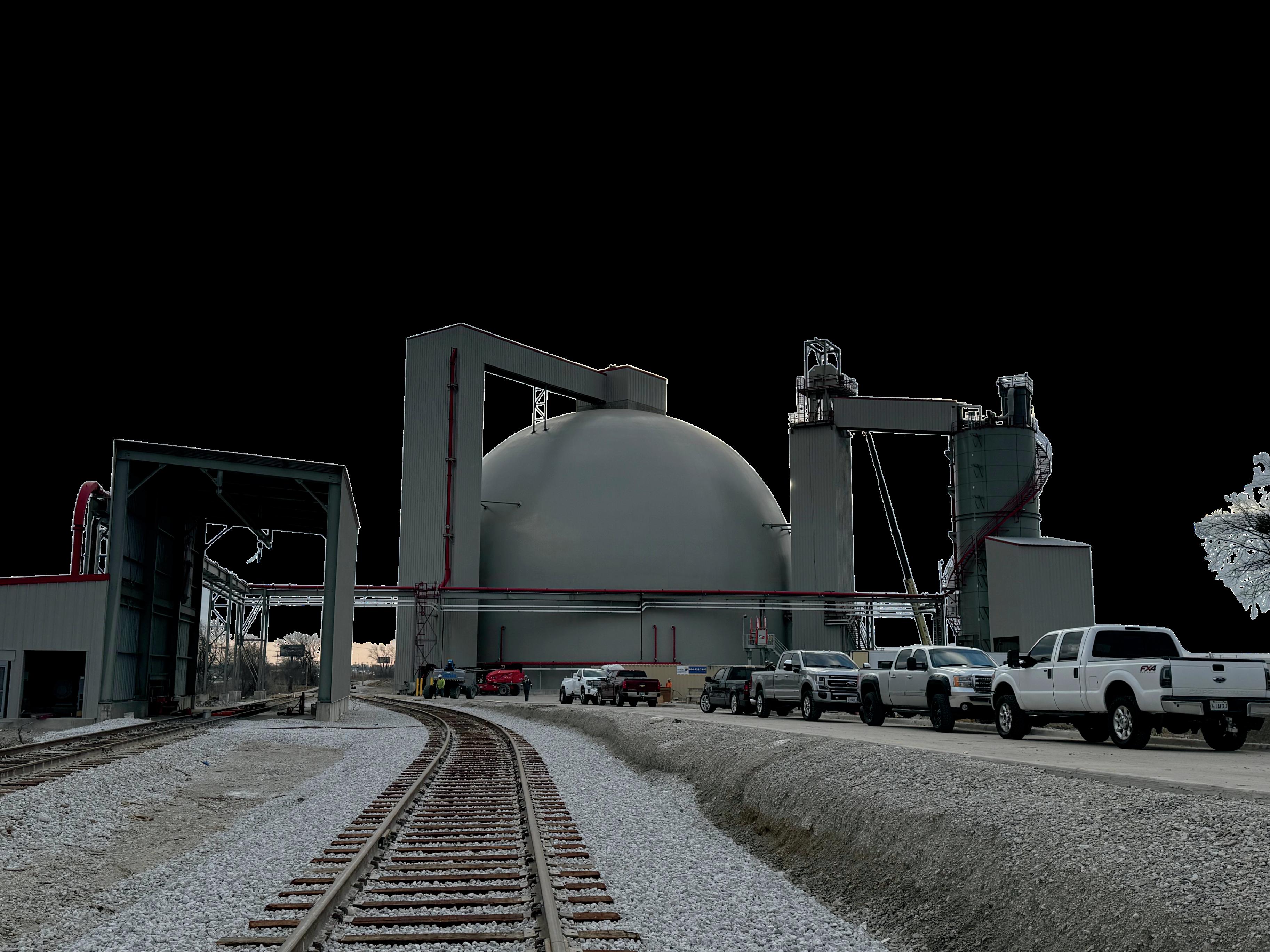
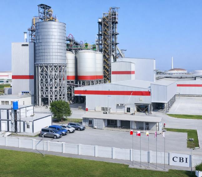
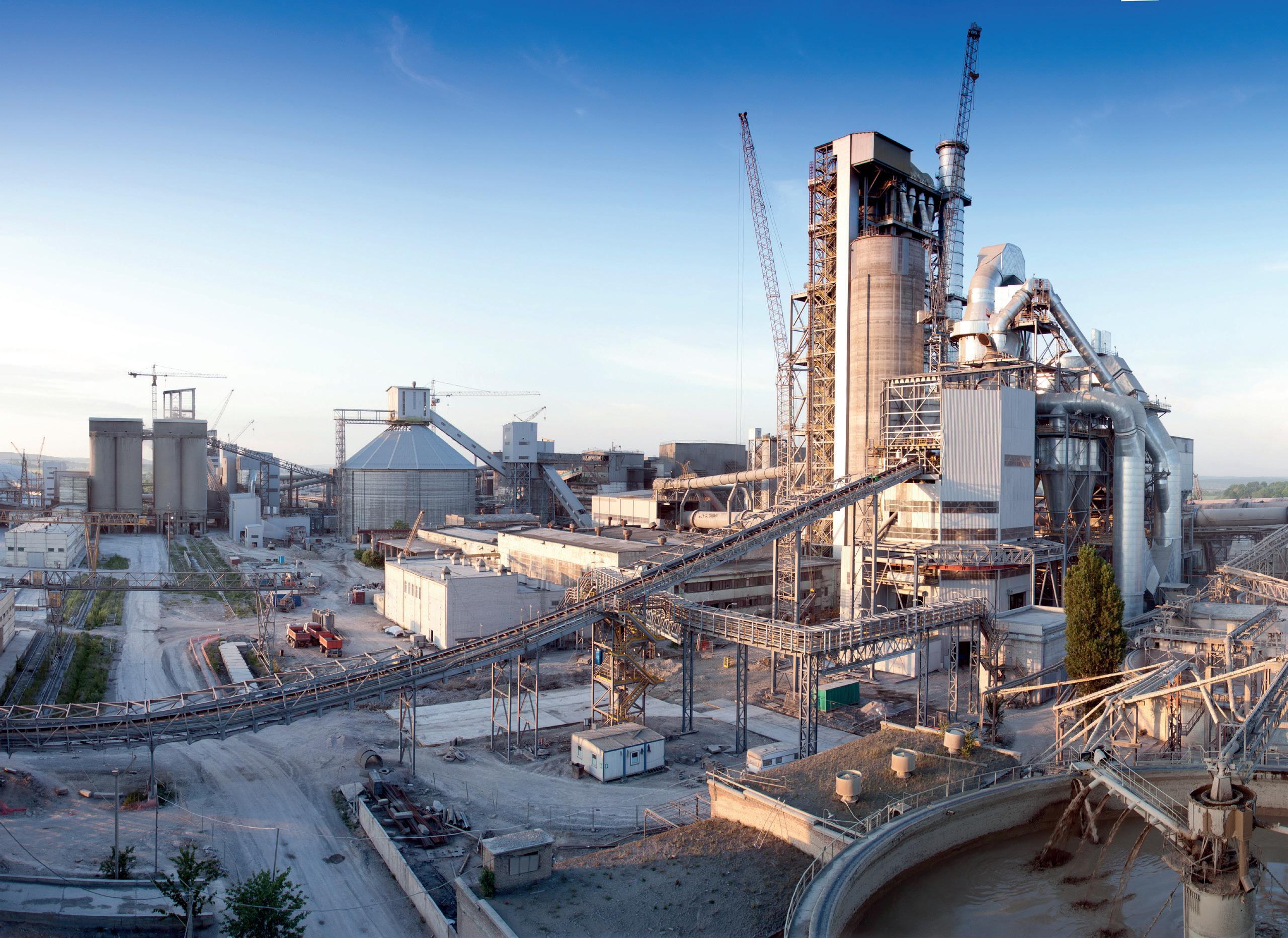
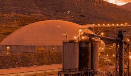
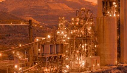
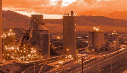
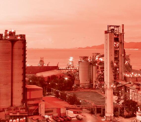
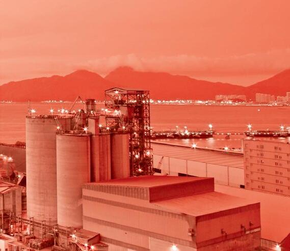
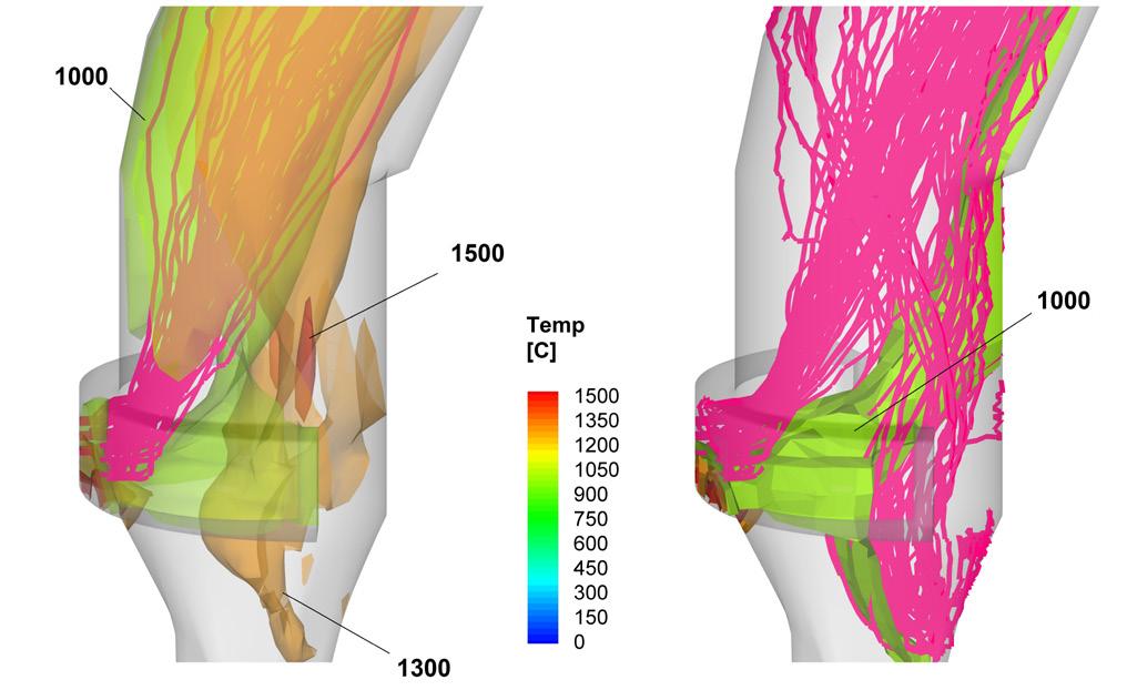
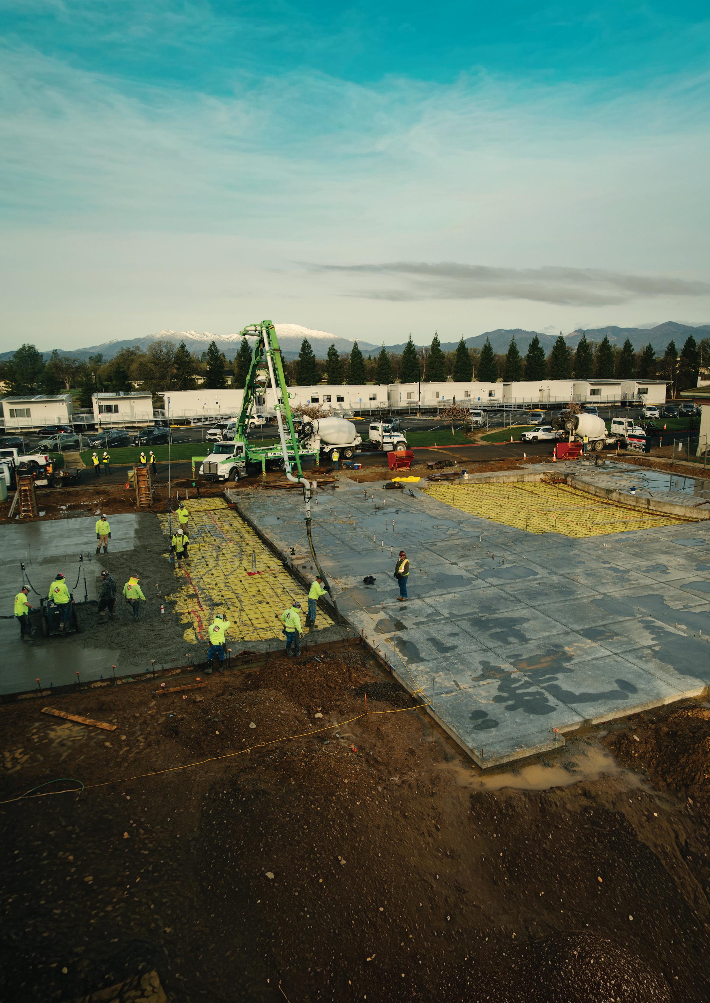
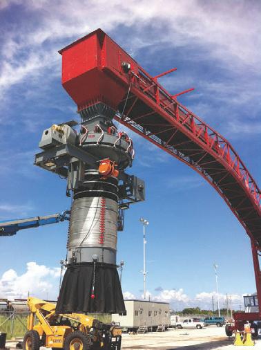
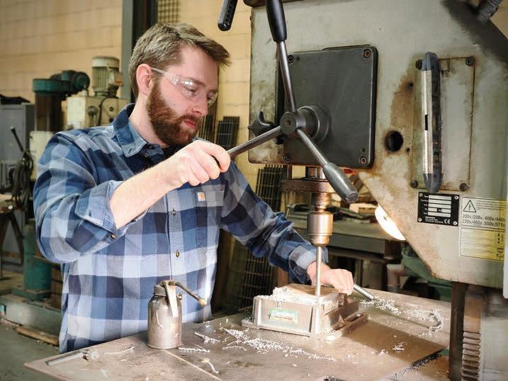
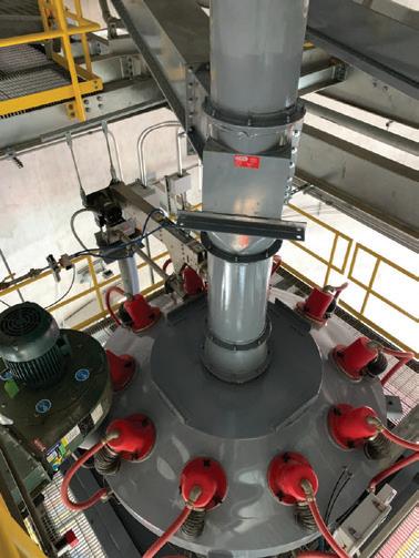
The decision to build the world’s largest flash calciner wasn’t about chasing a record. It was solving a structural problem. Nana Yaw Ayensu, CBI Ghana Ltd., tells the story of how West Africa’s most ambitious green cement investment moved from commitment to full-scale production and offers lessons for an entire region.
CONVEYING
18 Improving Splice Joint Reliability: Part 2
In the concluding part of this feature, Rob van Oijen, one of Europe’s most highly regarded application engineers, explores splice material shelf-life, the use of splice kits, and the advantages of finger-spliced joints.
LOADING, UNLOADING, & LOGISTICS
25 Loading Optimisation Starts Upstream Reiner Bachthaler, Axians Industrial Applications & Services GmbH, explains how digital yard management and loading automation can optimise cement logistics workflows and improve plant efficiency.
PYROPROCESSING
31 Firing Up The Future
Dr Michail Akritopoulos and Dr Tahir Abbas, Cinar, examine how advanced combustion modelling tools are helping cement plants increase their use of alternative fuels while maintaining clinker output and reducing emissions.
39 Thoughts On Thermal Imaging
CE Thermal Vision Technology, explains how the effective use of thermal imaging demands a fundamental rethinking of how manufacturers approach total cost of ownership, data integration, and workforce development.
LOW CARBON CEMENTS
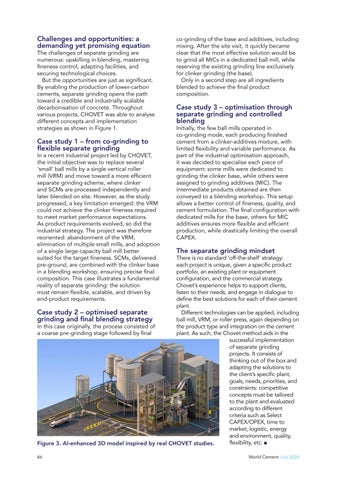
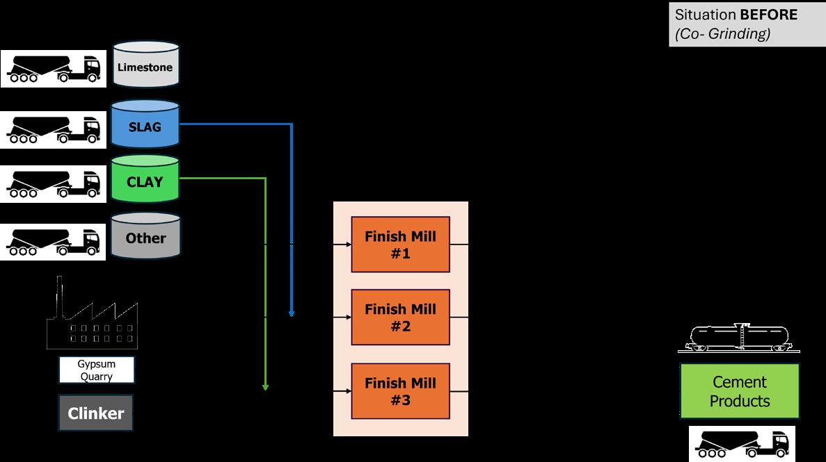
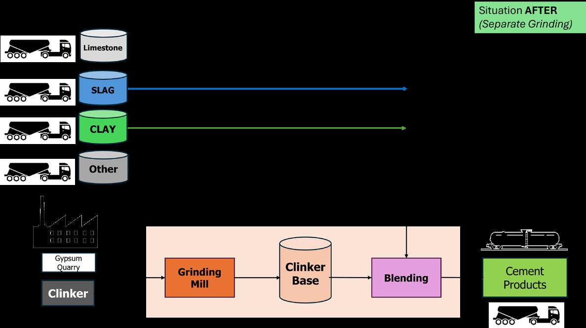
43 Separate Grinding For A Greener Future
Damien Michel and Thomas Lamare, CHOVET, explore how separate grinding can support the production of lower-carbon cements while improving flexibility in plant operations.
47 The Path To What’s Next Craig W. Hargis, Fortera, shows how performance-based standards and carbon mineralisation technology are enabling low-carbon cement to move from innovation to large-scale commercial deployment.
52 Breaking The Carbon Barrier
Susan McGarry, Ecocem, reveals how policy, procurement, and regulation are shaping the next phase of low-carbon cement adoption in Europe.
DIGITALISATION
55 Digitalisation: Driving Plant Performance
Bilal Ahmad Hajam, CEMENTINDUSNEED, explores how digitalisation and integrated information flow are transforming performance.
58 The Digital Cement Age
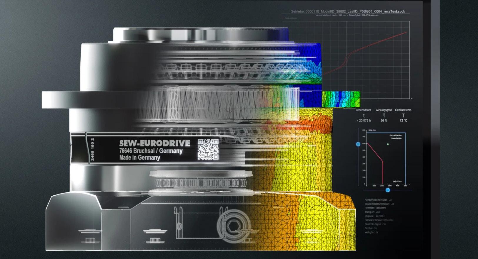
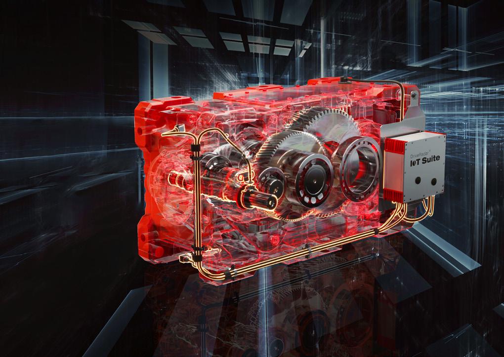
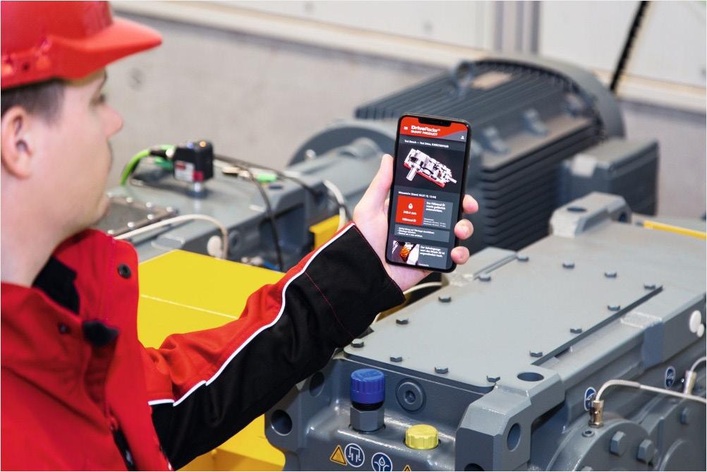
Andy Turner, SEW-EURODRIVE UK, looks at how the Industrial Internet of Things (IIoT), along with data analytics, AI, and digital twins, can drive consistency and efficiency in cement production.
ON THE COVER CONTENTS
This month’s cover showcases FR8Works next-generation truck ticketing solution for raw materials, powered by PSCL. Built for sites of any size, FR8Works modernises ticketing with self-service kiosks that automate paperwork, increase throughput, and makes your shipments available in real time from the FR8Works cloud dashboard.
PREC SION IN EVERY DECISION.
THE QCX® QUALITY CONTROL PLATFORM
The integrated QCX suite combines software, hardware, and services with our in-depth understanding of cement processes. Its scalable, modular design allows you to automate individual tasks or the entire sample handling process, delivering highly accurate results, complete sample traceability, and increased laboratory capacity.
Explore our sampling, preparation, and analysis systems
COMMENT
Sales Manager: Ian Lewis ian.lewis@palladianpublications.com
Sales Executive: Sebastian d’Entrecasteaux seb.dentre@palladianpublications.com
Head of Events: Louise Cameron louise.cameron@palladianpublications.com
Digital Events Coordinator: Merili Jurivete merili.jurivete@palladianpublications.com
Digital Content Coordinator: Kristian Ilasko kristian.ilasko@palladianpublications.com
Video & Motion Graphics: Amélie Meury-Cashman amelie.meury-cashman@palladianpublications.com
Digital Administrator: Nicole Harman-Smith nicole.harman-smith@palladianpublications.com
Administration Manager: Laura White laura.white@palladianpublications.com
Reprints reprints@worldcement.com
DAVID BIZLEY, SENIOR EDITOR
For those amongst the World Cement readership who have somehow managed to miss the news: the FIFA World Cup is well underway. For those not interested in football (not soccer), apologies, but there is a point behind this – please bear with me. With this World Cup taking place across three nations – Canada, the US, and Mexico – much fuss been made and many tabloid news stories have been written on the topic of how players from typically cooler climates will endure the heat.
FIFA’s solution has been to implement compulsory 3 minute ‘hydration breaks’ midway through each half of every match, effectively turning the ‘game of two halves’ into a game of four quarters. Needless to say, this has not been a popular change amongst the players, the coaches, the pundits, or the audiences. Particularly farcical is the fact that hydration breaks are being implemented at matches taking place in enclosed, air-conditioned venues, like the Dallas Stadium (usually known as the AT&T Stadium) – all in the interests of fairness.
CBP019982
SUBSCRIPTIONS
Annual subscription (published monthly): £160 UK including postage/£175 (€245) overseas (postage airmail)/US$280 USA/Canada (postage airmail). Two year subscription (published monthly): £256 UK including postage/£280 (€392) overseas (postage airmail)/US$448 USA/Canada (postage airmail). Claims for non receipt of issues must be made within 4 months of publication of the issue or they will not be honoured without charge.
Applicable only to USA and Canada: WORLD CEMENT (ISSN No: 0263-6050, USPS No: 020-996) is published monthly by Palladian Publications, GBR and is distributed in the USA by Asendia USA, 17B S Middlesex Ave, Monroe NJ 08831.
Periodicals postage paid at Philadelphia, PA and additional mailing offices. POSTMASTER: send address changes to World Cement, 701C Ashland Ave, Folcroft PA 19032
Now whilst it’s true that practically nobody involved in any of the actual football being played is in favour of the new regime, the TV advertising slots sold during these breaks are estimated to be worth a cool and refreshing US$250 million in the US alone, and approximately US$1 billion worldwide; making TV executives the true winners of the 2026 World Cup.
Anyway… where was I going with this? Oh, yes, well those worried about the impact of high temperatures on players from Europe at least need not have worried as the continent endures (at the time of writing) a series of lethal heatwaves making the Americas seem cool in contrast. The UK’s Met Office issued a rare ‘red’ heat warning that covered much of Southern England and parts of Wales with the UK’s 49 year June temperature record of 35.6˚C being broken on 24 June (36.1˚C). And then on 25 June (36.7˚C). And then again on 26 June (37.3˚C).
And that, by the standards of what has been happening in mainland Europe, is mild with temperatures peaking at 45.1˚C in Spain and 44.3˚C in France. As well as serving as a worrying indicator of what’s in store for the world if climate change is left to proceed unabated, the current European heatwave (gradually moving eastwards at this point) has so far resulted in 1300 excess deaths, a nuclear reactor shutting down, schools closing, infrastructure failing, and dozens of drowning deaths as people seek refuge from the soaring temperatures.
So here we are; another year, another set of temperature records broken. All of which, according to scientists at World Weather Attribution, would have been impossible if not for man-made climate change. All of this goes to underline the importance of the cement industry’s decarbonisation efforts – everything that producers can do to reduce emissions today, helps secure a better future for us all.
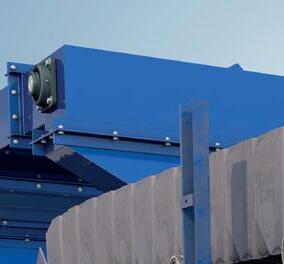
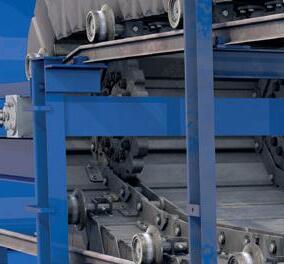
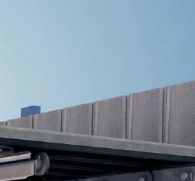
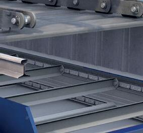
Convey units
Truck loading
NEWS
Ambuja Cements and Leilac partner to develop commercial- scale low-carbon cement
Ambuja Cements, the cement and building materials company of the Adani Group, has partnered with Leilac Limited, a UK-headquartered clean technology company specialising in carbon capture and electrification solutions for emissions-intensive industries, including cement and lime manufacturing.
This partnership marks an important step in Ambuja Cements’ broader decarbonisation strategy and supports its SBTi-validated net zero target for 2050. As the Company advances the electrification of cement manufacturing to increase the use of renewable energy, backed by nearly 1 GW of captive green power, it is laying the groundwork to scale breakthrough solutions such as carbon capture. Importantly, this collaboration is expected to improve the economics of carbon capture, strengthening the business case for large-scale deployment of carbon capture and utilisation.
The commercial demonstration project at Ambuja Cements’ 6.6 MTPA Sanghi plant in Sanghipuram, Kutch, will evaluate the integration of Leilac’s carbon capture and hybrid electric heating technology to support lower-emission cement production through greater use of renewable electricity and the capture of unavoidable process carbon dioxide. The technology is designed to enable a pathway where coal consumption can be reduced to zero, while allowing alternate fuels to be used flexibly.
Subject to successful demonstration, the project, positioned as the largest industrial-scale plant of its kind globally, could be scaled up by 7x to 8x to capture more than 1 million tpy of CO2, helping establish a scalable pathway for low-carbon cement production in India and beyond.
Karan Adani, Director, Ambuja Cements, said: “The cement industry’s transition to a lower-carbon future will require bold thinking, technological innovation and collaboration across the value chain. Our partnership with Leilac reflects our commitment to evaluating next-generation technologies that can reduce
process emissions while improving energy efficiency and supporting long-term sustainable growth. This initiative aligns with our vision of building world-class manufacturing operations for the future.”
Daniel Rennie, CEO, Leilac Limited, said: “Ambuja Cements operates one of the world’s largest and most advanced cement manufacturing networks. We’re delighted to begin this collaboration to deliver a commercial-scale project for low-cost, low-carbon cement production. Together, we aim to demonstrate an economic, replicable and future-proof solution for the global cement industry.”
Cemvision and Siemens partner to advance next-generation cement production
Cemvision and Siemens AB have signed a strategic partnership to develop and scale near-zero carbon cement production facilities. The collaboration brings together Cemvision’s breakthrough technology with Siemens’ industrial systems expertise and global reach –creating a rare convergence of innovation and industrial capability at a critical moment for climate action.
Cement production is one of the most overlooked climate culprits. It accounts for roughly 7 – 8% of global CO2 emissions. Yet the industry has remained largely unchanged for decades. Cemvision is changing that equation.
The company has developed “Re-ment,” a circular cement produced primarily from industrial residuals and by-products – materials that would otherwise be discarded. By combining these recovered materials with fossil-free energy, Cemvision has created technology capable of reducing emissions by up to 95% compared to conventional cement production.
The partnership encompasses multiple dimensions, with Siemens positioned as a preferred supplier for Cemvision’s production facilities. Covering a broad range of products and services, including medium and low voltage distribution, control systems, variable speed drives, process instrumentation,
NEWS
FICEM Technical Congress
and cybersecurity, as well as digital solutions such as plant lifecycle management, IT/OT integration, and plant simulation. The parties are also exploring a virtual plant (digital twin) solution to support pre-design activities, value engineering, and a virtual ramp-up of Cemvision’s facilities.
31 August – 04 September, 2026
Mexico City, Mexico https://ficem.org/eventos-ficem
Additionally, the partners are exploring Siemens, becoming an early customer of Cemvision’s cement within its own supply chain, providing both market validation and demand certainty.
“Digital twins and advanced process control can optimise cement production in ways that weren’t possible before. By combining Cemvision’s cement chemistry expertise with our digital and automation capabilities, we’re creating a blueprint for next-generation sustainable manufacturing,” says Andrea Waenerlund, CEO Siemens, Nordics.
“This partnership aligns with both companies’ sustainability agendas – Cemvision’s mission to decarbonise cement production and Siemens’ focus on green industrial transformation. We are looking forward to exploring the full potential of this partnership,” says Oscar Hållén, CEO of Cemvision.
The partnership is formalised through a Memorandum of Understanding, with both companies committed to advancing the collaboration toward commercial deployment.
Global Innovation Challenge launches a new search for AI solutions that enable low-carbon cement and concrete
The Global Cement and Concrete Association (GCCA) is inviting start-ups to submit entries for its Innovandi Open Challenge 2026, with a focus on using artificial intelligence (AI) to accelerate the decarbonisation of the world’s two most essential construction materials. Winning technologies are expected to build on AI’s existing deployment in the industry, from enhancing cement and concrete mixes, to optimising manufacturing processes and reducing environmental impacts.
Submissions should impact cement manufacturing or concrete production, or both, and could cover solutions including:
f Low-clinker and low-carbon materials, and mix design.
f Kiln, fuel, energy, and process optimisation.
f Production control and semi-/autonomous operations.
f CO2 measurement, prediction, and product carbon footprint optimisation.
Announced at the GCCA’s event at London Climate Action Week, Thomas Guillot, Chief Executive of the GCCA, commented: “Innovation and new technologies can be transformative, particularly for crucial industries that have existed for hundreds of years.
Cement and concrete play a vital role in enabling a resilient and sustainable world, which is why our members embrace cutting edge solutions to ensure that the industry continues to evolve and decarbonise.“
NEWS
“Our Open Challenge is a first of its kind, industry-led accelerator and over the past four years we have seen a variety of exciting new technologies being explored. We are now calling for start-ups with ingenious AI solutions to come and join us in our journey towards net zero concrete.”
The GCCA and its members understand the key role that innovation will play in unlocking a net zero future for concrete, which is why successful companies will gain unique access to the expertise and infrastructure of more than 40 members worldwide.
Through collaborative partnerships, our members will help them test and develop their ideas in a commercial environment, and adapt them with insight from their target market.
Since the Open Challenge’s creation four years ago, it has been a very successful platform with over 300 start-ups applying for the programme globally. Following a rigorous evaluation and pitch process, 15 start-ups have formed consortia with member companies and are actively developing their technologies.
Sinoma EC’s Waste Heat/Geothermal equipment bound for Malaysia
Recently, the independently developed “Waste Heat + Geothermal Energy” complementary energy technology of Sinoma Energy Conservation Ltd. (hereinafter referred to as Sinoma EC) ushered in a milestone: the first batch of equipment for its Malaysia project was successfully assembled and shipped from Shanghai Port. This marks the overseas debut of Sinoma EC’s geothermal energy business and a breakthrough in its global market expansion in this field.
As Sinoma EC’s first overseas project integrating industrial waste heat utilisation and geothermal energy exploitation, the initiative leverages core proprietary technologies including the non-discriminatory coupling of industrial waste heat and geothermal energy. It achieves year-round effective integration of local shallow geothermal resources with industrial waste heat, building an efficient and low-carbon complementary energy supply system to deliver clean energy solutions for Malaysia’s cement industry.
The formal launch and implementation of this project demonstrate that Sinoma EC has acquired
full capabilities for the development and operation of international geothermal projects. Serving as a bridgehead for the company to further explore the Southeast Asian market, the Malaysia project will pave the way for the global expansion of its geothermal business and help elevate the influence of Chinese technologies in the international green energy sector.
Holcim’s Tilbury Cement Works commences operations
Holcim UK has reached a significant marker in the development of its flagship Tilbury Cement Works, with the plant now commencing import and distribution of cement. The first deep-sea vessel has discharged material into the site, heralding the transition from construction through to active operations.
Located at the Port of Tilbury, the new cement works combines deep-water marine access with large-scale storage, automated logistics and a modular grinding and blending system that will come online later in 2026. This development strengthens Holcim’s national network by placing high-volume processing capacity directly at the point of demand, reducing reliance on long-distance inland transport and improving supply resilience.
Tim Fry, Project Manager at Holcim UK, said: “Initiating import and distribution of cementitious materials is a major step forward for Tilbury Cement Works and for Holcim’s ability to serve customers across the South East. This phase demonstrates the strength of the systems we’ve built, from marine logistics to storage and dispatch, and reflects the hard work of everyone involved in bringing this facility to life. As construction concludes in 2026 and we move into full operations, Tilbury will provide the flexibility, reliability and capacity to support our customers with a range of conventional, low carbon and circular cementitious materials.”
Tilbury’s flagship facility is geared to support 24/7 operations and includes a new ship-to-shore conveyor system, enclosed belt conveyors and the UK’s first 30 000 t cement dome silo. Material is transferred directly from vessel to storage, before being processed and dispatched through six loading heads and five weighbridges.
ENGINEERING
40 YEARS OF THE FUTURE OF CEMENT
For four decades, PENTA Engineering Corporation has par tnered with cement producers worldwide to deliver top-tier engineering solutions f rom initial concept through f inal completion.
Our multidisciplinar y team combines deep industr y experience with for ward-thinking approaches to solve complex challenges and build facilities that perform today and are ready for tomorrow.
We thank our clients, par tners, and employees for being par t of our journey.
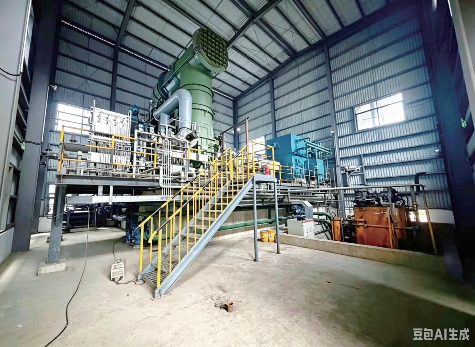
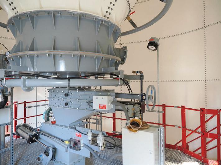
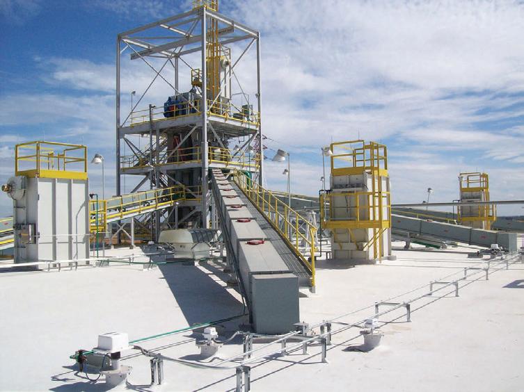
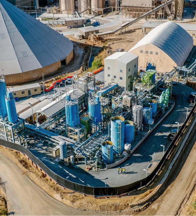
The decision to build the world's largest flash calciner wasn't about chasing a record. It was solving a structural problem.
Nana Yaw Ayensu, CBI Ghana Ltd., tells the story of how West Africa's most ambitious green cement investment moved from commitment to full-scale production and offers lessons for an entire region.
he decision to build the world's largest calcined clay plant did not begin with a sustainability target. It began with a supply chain problem that Ghana's cement industry had absorbed for decades.
Ghana is one of Africa's largest importers of clinker, the energy-intensive intermediate that underpins conventional portland cement. Industry estimates place the country's annual clinker import bill at close to US$500 million.
That dependency ties the price of cement directly to global energy costs, shipping rates, and the depreciation pressure on the cedi. When the cedi weakened sharply between 2022 and 2024, retail cement prices in Accra and Kumasi climbed to between GHS110 and GHS135 per 50 kg bag, pushing construction costs beyond the reach of many builders.
CBI Ghana Ltd., founded in 2017 at the Tema Free Zones Enclave, treated this dependency as a problem to be engineered away. Its answer was limestone calcined clay cement, or LC3: a cement technology that replaces a significant share of clinker with calcined clay and limestone, reduces CO2 emissions by up to 40% versus conventional portland cement, and uses raw materials that are abundant across Ghana.
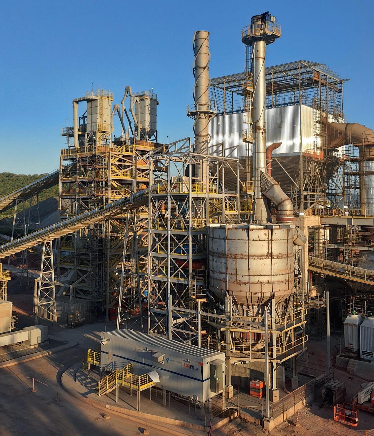
The strategic question was one of scale. CBI Ghana Ltd. chose to pursue LC3 not as a pilot but as a full industrial operation. That commitment, a US$110 million investment, was officially commissioned in March 2026 by H.E. President John Dramani Mahama and is recognised as the largest calcined clay plant of its kind in the world.
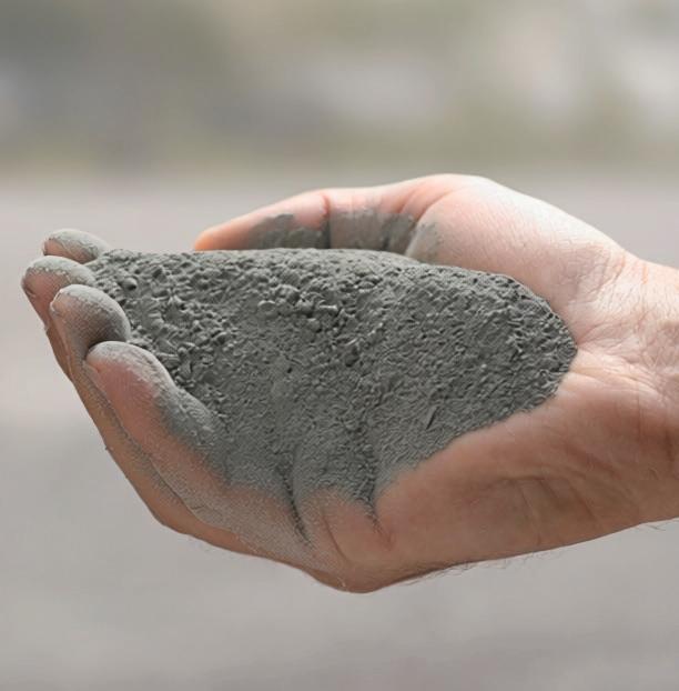
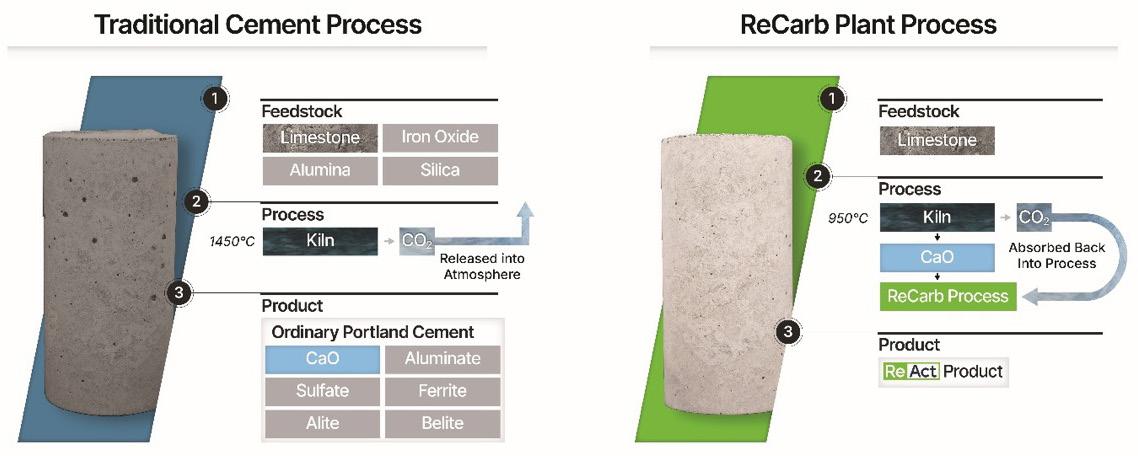
The technology, in plain terms LC3 works on a straightforward idea. Kaolinitic clay, heated to a controlled temperature, becomes a reactive material that can replace part of the clinker in cement. Combined with limestone, this calcined clay produces a cement with strength comparable to conventional grades but with a markedly lower carbon footprint.
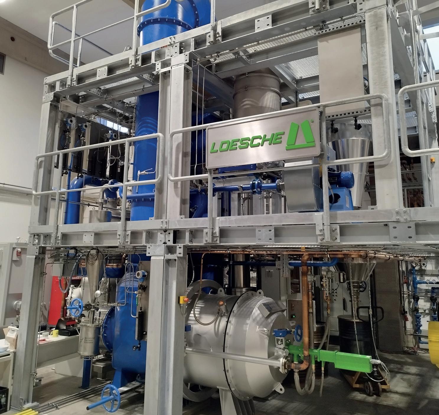
The challenge is consistency. Producing reactive calcined clay at industrial volume, from clay of varying quality and in a humid tropical climate, demands precise and reliable processing equipment. CBI Ghana Ltd. awarded the calcination technology contract to Fuller Technologies whose system was selected for its proven efficiency and its ability to hold consistent quality at the throughput the project required.
The calcined clay produced at Tema is blended with clinker and with limestone from a licensed quarry in the Eastern Region.
The blend is calibrated by grade and verified through daily testing at the company's on-site laboratory. Supa Power 42.5R uses 35 – 45% clinker substitution, while Supa Fast 32.5R limits clinker content to no more than 45%, the lowest for any 32.5R grade cement in the world.
The plant's reach is not limited to CBI Ghana Ltd.'s own products. It also supplies calcined clay to other producers in the Ghanaian market, extending the decarbonisation benefit of LC3 technology across a wider share of national cement output than CBI Ghana Ltd.'s own volumes alone would allow.
The challenges behind the milestone
The path from commitment to commissioned plant was not linear. Three challenges stood out.
"Every
year, Ghana spends close to half a billion US dollars importing clinker. That is hard currency that can stabilise our local currency. From this plant, the largest of its kind in the world, we are replacing imported clinker with locally produced calcined clay."
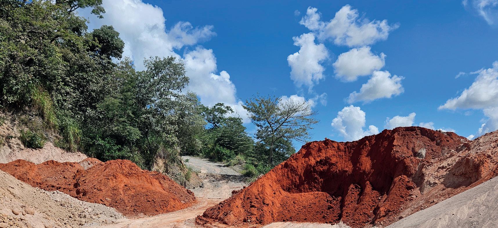
CBI Ghana Ltd.'s clay is sourced primarily from Torgome in the Volta Region. Establishing a dependable, high-volume supply of a material not previously mined at industrial scale in Ghana required investment in logistics and in quality control since clay chemistry varies between sites and must be managed carefully before it reaches the calciner.
Standards
When CBI Ghana Ltd. began scaling LC3 production, Ghana had no national standard for this class of cement.
Existing portland cement standards did not accommodate the clinker substitution LC3 requires, which risked blocking the product from public and private projects where specification compliance is a procurement condition. Working with the Ghana Standards Authority and research partners, the industry helped bring about GS PAS 5:2024, Ghana's first national standard for LC3 cement. Its adoption was a precondition for commercial scale.
Financing and acceptance
A US$110 million investment in a frontier market required a coalition of partners, and CBI Ghana Ltd. assembled strategic and development finance backing to support it. Certification alone, however, does not win a market accustomed to conventional cement. CBI Ghana Ltd. invested in technical engagement with engineers, contractors, and developers to build the confidence required to specify LC3 across demanding applications.
Performance in the field
The plant supports a product range certified by the Ghana Standards Authority, with each grade engineered for a distinct kind of work.
Supa Fast 32.5R, the general-purpose LC3 grade, is the workhorse of the range. It is used for plastering,
screeding, block-laying, general masonry and mortar, and low-to-medium-strength concrete. Its low heat of hydration reduces thermal cracking in blocks and plaster, while its resistance to sulfate
attack and chloride ingress makes it well suited to coastal and waterlogged sites along the Greater Accra coastline, where dampness and efflorescence are common problems with conventional cements.
Supa Power 42.5R, the high-performance LC3 grade, is engineered for load-bearing work: suspended concrete slabs, foundations, columns, beams, structural blockwork, and precast elements, as well as marine and harbour works, bridges, and flyovers. It reaches a compressive strength of 25 MPa at two days and around 49 MPa at 28 days, and its dense microstructure resists chloride ingress in coastal exposure. Its rapid early strength supports faster formwork striking and shorter construction cycles.
Supa Hard 52.5N, a premium portland cement certified under GS 1118:2016 and aligned with EN 197-1, serves the most demanding specialist work: pre-stressed and post-tensioned elements, aviation infrastructure such as runway aprons and taxiways, heavy-duty industrial flooring, high-rise load-bearing members, and high-strength concrete at C50/60 and above. It reaches around 59 MPa at 28 days and is also available in 42 t bulk tanker loads from the Tema plant.
Project at a glance
Operator
Location
Total investment
Annual calcined clay capacity
Technology
Equipment supplier
CO2 reduction
Commissioned
Certification
CBI Ghana Ltd. (Supacem brand)
Free Zones Enclave, Tema, Ghana
US$110 million
Exceeds 400 000 tpy
LC3 (limestone calcined clay cement)
FLSmidth now Fuller Technologies
Up to 40% versus conventional Portland cement
By H.E. President John Dramani Mahama, March 2026
Ghana Standards Authority (GS PAS 5:2024 / GS 1118:2016)
Table 2. Selected Ghanaian projects built with Supacem cement.
Project Type of work
Borteyman Sports Complex, Accra
Tema Port extension
Jamestown Fishing Harbour
The Ruby by Myla Homes
Residential and commercial builds nationwide
Structural concrete works
Marine and heavy structural works
Marine and harbour works
Residential development
General construction, plastering, blockwork
Proven on Ghana's landmark projects
The clearest evidence of Supacem's performance is where it has been used. Across structural, marine, and residential work, Supacem cement has been specified on some of Ghana's most significant recent projects, from large public infrastructure to private housing developments. These projects span the full range of Ghanaian construction. The marine and harbour works at Tema and Jamestown call for cement that resists chloride and sulfate attack under constant exposure to seawater, exactly the durability profile that the Supacem LC3 grades are engineered to deliver. The Borteyman Sports Complex demanded high-quality structural concrete, while residential developments such as The Ruby by Myla Homes show the brand's reach into Ghana's growing private housing market. Together they demonstrate that LC3 cement is not a niche or
CBI Ghana Ltd. chose to pursue LC3 not as a pilot but as a full industrial operation.
Table 1. Summary of the world's largest calcined clay plant, Tema, Ghana.
experimental material but a proven choice for serious construction.
A template for the region, and the road ahead
The significance of the Tema facility reaches beyond Ghana. Much of Sub-Saharan Africa shares the conditions that make this model relevant: abundant clay deposits, a cement sector built largely on grinding units that buy clinker rather than produce it, fast-growing construction demand, and regulators increasingly open to composite cement standards. Ghana's experience shows that LC3 can be produced reliably at industrial scale, financed in a frontier market, and supported by a fit-for-purpose national standard. For producers elsewhere in the region, that lowers both the technology risk and the regulatory uncertainty that usually accompany a first-of-kind investment.
The economic case is as much a part of the story as the technology. The Tema facility has created direct employment for engineers, technicians, laboratory staff, and plant operators, alongside a wider set of roles across clay extraction, transport, quarrying, and logistics. By producing calcined clay from local materials, the plant also reduces the volume of clinker Ghana must import, easing pressure on foreign currency and laying the basis for greater price stability in a strategically important market.
CBI Ghana Ltd.'s focus now turns to deepening its LC3 offering and building local technical expertise through its Tema laboratory, one of the most advanced in Ghana's cement sector. Ghana's cement demand is set to grow strongly over the coming years, driven by urbanisation, housing needs, and public infrastructure. Meeting that demand with a locally produced, lower-carbon cement that reduces import dependency and sustains Ghanaian jobs is both a commercial strategy and an industrial policy with a long horizon.
The plant is operational. The technology works at scale. The products are certified and performing. For the region's cement industry, the case for LC3 at scale no longer rests on projection. It rests on results.
"What CBI Ghana Ltd. has built here is a statement about Ghanaian potential. Ghana's industrial future will be built by your hands."
H.E. John Dramani Mahama, President of the Republic of Ghana, Tema, March 2026.
Process improvement is mastering ESG goals while maximizing efficiency.
Your industry demands high returns without compromising environmental, social, governance and safety objectives – all while addressing the demand for critical new energy minerals. We offer an innovative portfolio of monitoring, analytics and automation excellence, as well as extensive cross-industry expertise. Do you want to learn more? endress.com/primaries-metal
TO NET ZERO OUR PATHWAY
U FINES
GUARD
In the concluding part of this feature, Rob van Oijen, one of Europe’s most highly regarded application engineers, explores splice material shelf-life, the use of splice kits, and the advantages of finger-spliced joints.
The concluding part of this special feature highlights the problems associated with buying generic splice materials in bulk, the advantages of splice kits, splice material shelf-life management, ‘speciality’ compounds, and the advantages of finger-spliced joints.
Limited ‘effective use’ lifespan
As with most products in the commercial world, buying large quantities usually brings a
price benefit. The other advantages are avoiding the need for frequent repeat orders and, even more importantly, ensuring adequate stock levels. The downside of buying large quantities is that there are several different ‘task-specific’ materials and each has an individual restriction regarding its functional lifetime (shelf-life), after which the effectiveness of the material begins to decline, in some cases very rapidly indeed.
Unfortunately, there are no standard guidelines, it is just a matter of what is in the mix, how their
molecular structure and behaviour (effectiveness) changes over time, their curing speed at ambient temperature, and so on. This means that shelf-life can range from one month following manufacture up to 12 months, with various permutations in between. Generally speaking, splice materials for speciality belting have the shortest shelf-life (as short as only one month), with certain fire-, oil-, or heat-resistant types ranging from 3 to 6 months and the longest (up to 12 months) is more typical for ‘regular’ abrasion resistant belts.
To add further complexity, recommended shelf-life varies between manufacturers. Just as the rubber compound recipes used for the outer covers and inter-ply skims vary from manufacturer to manufacturer, so do the various rubber-based splice materials. These include uncured inter-ply rubber (used to rebuild the belt carcass), the uncured cover rubber used to rebuild the belt’s cover area, and uncured rubberised fabrics used as reinforcements in heavy duty/high tensile splices.
As with the food products, splicing materials need to be stored according to the recommended conditions shown on the packaging (especially temperature) and should not be used once the use-by date has passed. To do so is a false economy and the first thing that suffers is the all-important adhesion properties.
‘Task-specific’ splice materials
As explained in Part 1,* all splicing materials must be a compatible match to bond effectively with each other and have very similar mechanical properties and characteristics compared to the rubber compounds used to make the belt. The more specialised the belt grade, such as fire resistant for example, the more critical matching becomes. If the rubber materials used to create the splice joint do not have the equivalent resistance to fire, oil, or heat, then a weak spot is automatically created both in terms of how the rubber reacts to exposure and its adhesive properties. The negative effects of incompatibility are unlikely to be seen in the very short term but over time reliability will suffer, leading to more and more stoppages to carry out splice repairs. To avoid such problems, it is best to use splicing materials supplied by, or at least recommended by, the manufacturer of the belt.
Customised ‘ready to use’ splice kits
When splicing special cover-grade belts, such as oil-, fire-, or heat-resistant types, the most reliable method of ensuring that the splice materials closely match the belt rubber is to use
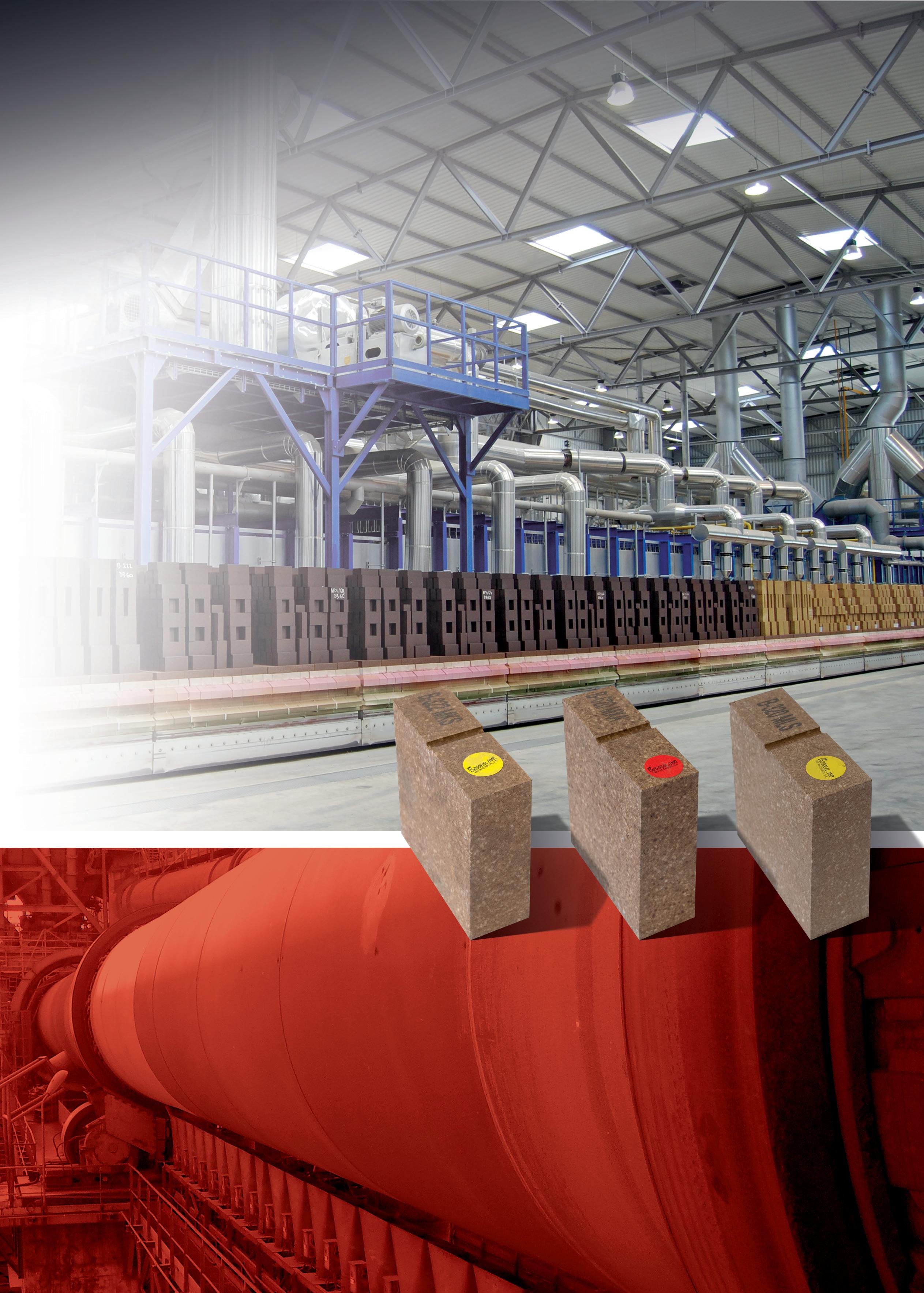
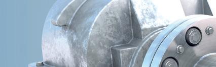
Figure 1. Shelf-life largely depends on what is in the mix.
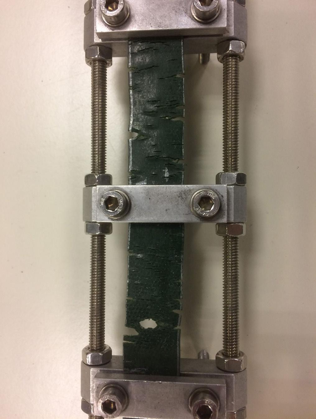
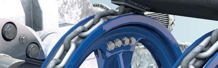
Figure 2. Rubber splice materials should have equivalent resistance to fire, oil, or heat.
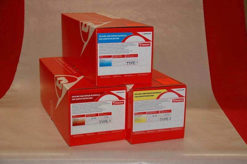
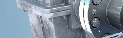
Figure 3. Splice kits are invaluable for special cover grades.
Refractory Solutions for the C Cement Industry
a complete splicing kit produced or supplied by the belt manufacturer.
Such kits contain all the necessary materials including cover rubber, interply rubber, and rubber solutions (also called ‘cement’ by some suppliers). Kits are also available for different belt types including steel-reinforced and also pre-formed splicing kits for steel cord belting.
Ozone and ultraviolet resistance
Aside from the resistance that rubber compounds need to have against the different elements that damage and prematurely age the rubber, there is another form of resistance required that all rubber
compounds must have, which is the ability to resist the effects of ground-level ozone (O3) and ultraviolet light (UV) from sunlight and artificial (fluorescent) lighting.
Exposure (to light and air) is, of course, unavoidable and the damage they cause is considerable. The early signs of ozone attack are small cracks in the rubber surface, in some cases within weeks of first being fitted with much worse to come as the rubber becomes increasingly brittle and inflexible. Cracks form in rubber that is under tension at the points where the strain is the greatest, so splice joints are particularly vulnerable. The best advice is therefore to always insist on written confirmation that the splice materials purchased are fully resistant to the effects of ozone (O3) and ultraviolet light (UV).
Bonding methods
There are a number of ways that multi-ply conveyor belts can be joined/spliced. The primary methods are cold-glue splicing, hot vulcanisation using a heated press, and mechanical joints, although these are principally used for emergency repairs or for extremely lightweight or inaccessible belt applications. Cold glue splicing is generally seen as the easiest, fastest (lowest cost?) method, although this is a false economy if cold splicing is carried out correctly; preparation work is quite similar to hot vulcanisation and the glue needs at least 6 – 8 hours cure time, although many take a massive risk of a much quicker restart of the system, which can lead to early failure and need to repeat the process. Also, cold glue splicing is not an option when heat resistant belts are involved, as the glue would soften and separate with the temperature increase.
Hot vulcanisation using a mobile press requires handling and setting up the press, which takes some extra time and is therefore considered more costly. But in comparison to cold gluing, it produces a stronger, longer lasting, and more durable joint that is especially desirable on heavier duty applications. And when including the required cure time of cold glue, the whole process would not take any additional time.
Splicing methods – the advantages of finger splicing
For many years, the step splice has been the most commonly used splicing method but when looking to reduce the frequency of stoppages caused by splice joint failure by improving reliability, the increasingly popular choice is finger splicing. A step splice requires the removal of the length of the step of subsequent layers of fabric plies so that the two belt ends can be overlapped and either glued or hot vulcanised together. Although easier and faster to make, the main disadvantage of a step splice is that it will
Figure 4. The damage caused by ozone and ultraviolet exposure is considerable.
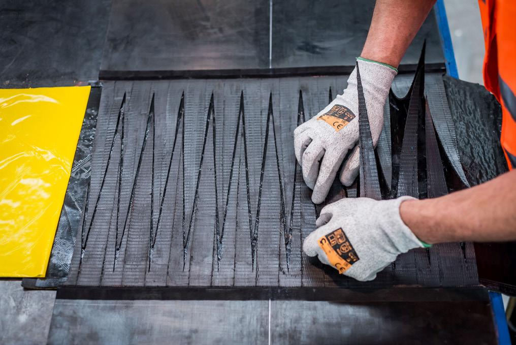
Figure 5. A finger splice may take longer but is stronger and more reliable.
always create a proportional loss of tensile strength equivalent to the strength of one ply.
By comparison, finger splicing is where a zigzag pattern is cut into both sides of the belt ends, creating several ‘fingers’ that are carefully aligned, interlocked together, and finally bonded using a hot vulcanising press to make a splice that is typically stronger and flatter than a conventional step splice while retaining a much higher level of longitudinal tensile strength.
As can be seen in Table 1, a 2-ply step splice only retains a maximum of 50% of the belt’s longitudinal tensile strength, a 3-ply step joint can only achieve a maximum tensile strength of 67%. In contrast, the finger splice method retains up to 90% of the belt’s ‘static’ tensile strength. Another reason for the increased reliability of the finger splice is that in dynamically stressed conditions (when the belt is working and under load) is that it is vastly superior in terms of resistance to dynamic failure.
How to improve splice joint reliability – the key points
f Use splicing materials supplied by (or recommended by) the manufacturer of the belt.
f Do not use incompatible and/or poor quality (cheap) splice materials.
f For cover grades such as oil-, fire-, and heat resistant, use splicing materials (preferably
GET CEMENT CO.
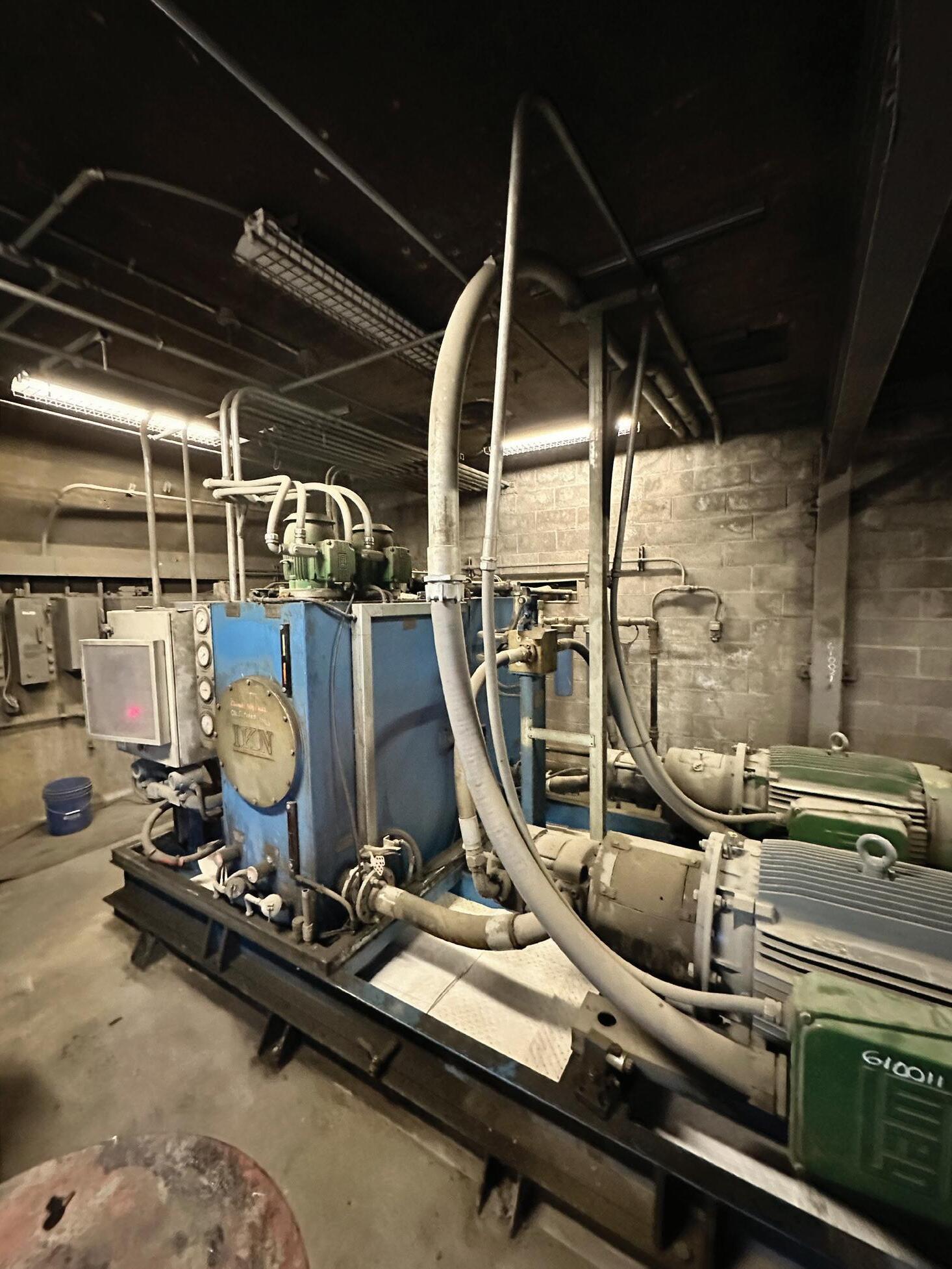
EXTENDS HYDRAULIC OIL
LIFE TO 5+ YEARS
After switching its clinker cooler hydraulic system to LE’s Equipower® Hydraulic Oil (4934), a cement manufacturer extended drains from 6 months to 5+ years – a 900% increase – saving $65,000 while reducing oil consumption, maintenance, and environmental impact.
splicing kits) with matching properties - do NOT use generic, non-task specific materials.
f Make sure that each splice material component/kit has been stored correctly.
f Check the ‘use-by’ date on the packaging. Discarding and replacing costs much less than a failed splice joint.
f Insist on written confirmation that the splice materials purchased are fully resistant to the effects of ozone (O3) and ultraviolet light (UV).
f Whenever possible, use finger-splice joints.
Notes
*For Part 1 of this two-part feature, see the May 2026 issue of WorldCement.
Table 1. Maximum tensile strength by belt splice type.
No. of plies Maximum % tensile strength
• International cement news
• Regional reports
• Market analysis
• Event previews and reviews
• In-depth technical articles
• In-depth regional analysis by key players in the industry
• Comprehensive technical reviews on all aspects of cement production, from the quarry face to despatch
Reiner Bachthaler, Axians Industrial Applications & Services GmbH, explains how digital yard management and loading automation can optimise cement logistics workflows and improve plant efficiency.
he dispatch of bulk goods like cement is currently undergoing a fundamental transformation.
Cement producers are confronted with a growing set of operational and economic challenges that directly affect loading and unloading
processes at their plants. While production itself has reached a high level of automation and efficiency, dispatch workflows are often still characterised by manual steps, isolated systems, and local optimisations.
One of the most pressing issues is the ongoing lack of skilled workers. Experienced personnel for weighing, loading supervision, and yard
coordination are increasingly difficult to recruit and retain. At the same time, customers expect significantly shorter delivery times and greater flexibility.
In parallel, cement plants are required to handle a growing number of transactions using the same infrastructure. More deliveries per day, more product variants, and more customer-specific requirements all increase complexity without necessarily increasing available space or resources. Finally, strong cost pressure across the industry forces operators to optimise every process step and to eliminate inefficiencies wherever possible.
These factors create a clear demand for professional digital yard and logistics management, especially loading automation. However, to successfully optimise and digitise bulk goods loading, it is necessary to take a step back and examine the entire cement logistics workflow.
The cement logistics workflow
The dispatch workflow starts long before the truck enters the plant. As soon as an order is placed, the loading process is affected. The subsequent transport planning, which can include coordination with carriers and assigning delivery slots, already determines which materials need to be picked up, when, from which plant, and in what quantities by which truck.
Once the truck arrives at the plant, all roads – or, in this case, processes – do not lead to Rome, but rather to bulk material loading, as it is the core step of the delivery workflow.
At plant check-in, the truck needs to be identified and weighed. Accurate weighing is crucial, as it provides the data basis for calculating the maximum allowed loading weight – a direct influence on the loading process. Lastly, the truck is assigned to a loading station and can proceed with the delivery workflow. This is when the check-in runs smoothly. In reality, poor planning, manual processes, and long waiting times can slow the check-in process and reduce throughput at the loading station and beyond.
The key insight here is that processes that take place well before the actual loading station have a measurable impact on loading, emphasising the importance of early planning and orchestration.
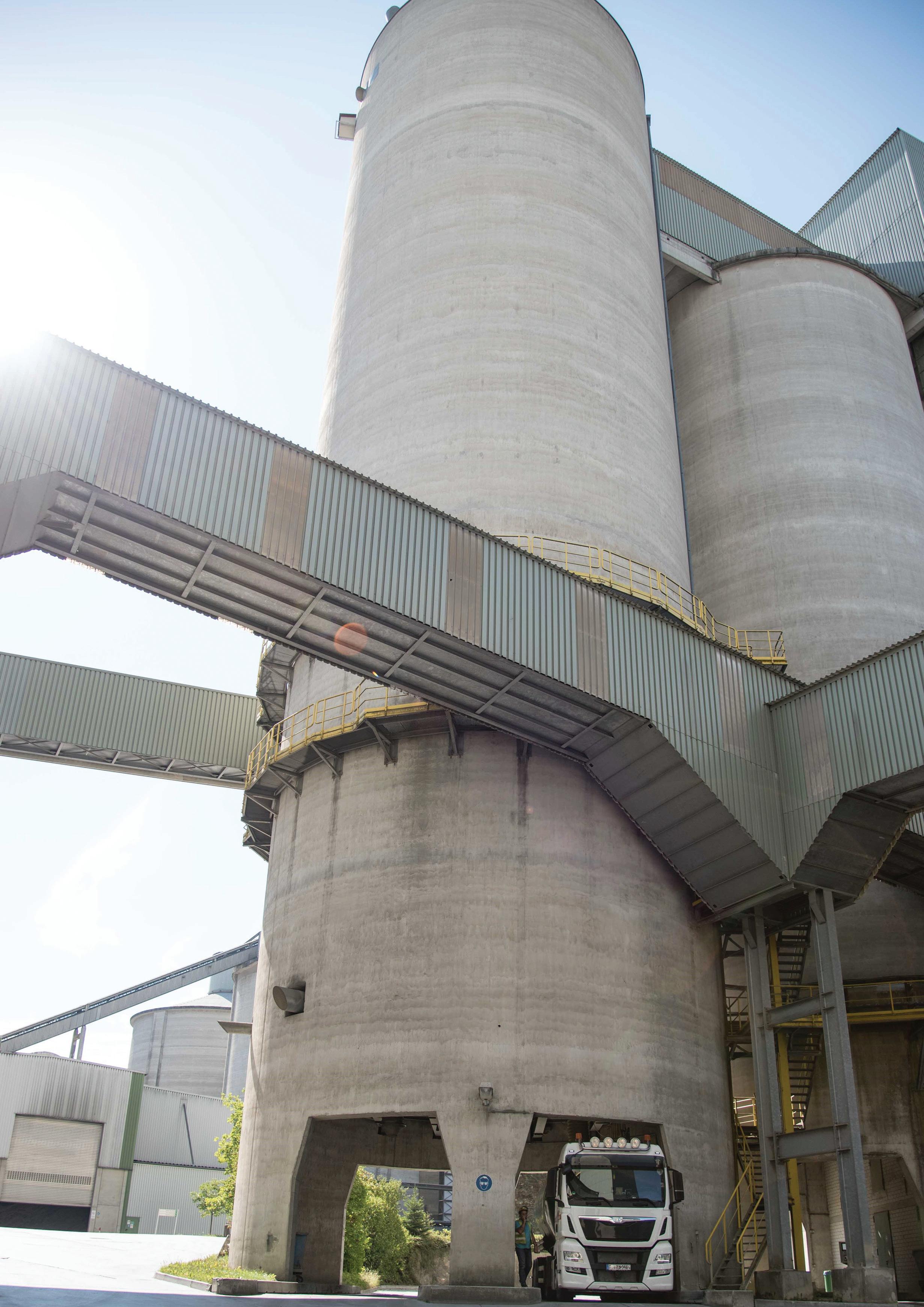
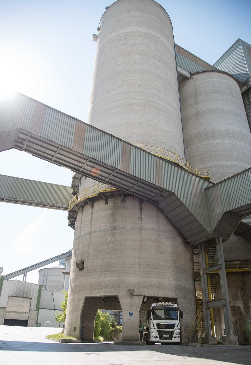
Automated loading at cement silo.
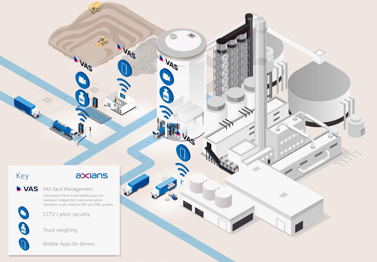
Overview: where VAS automates and optimises processes in the cement plant.
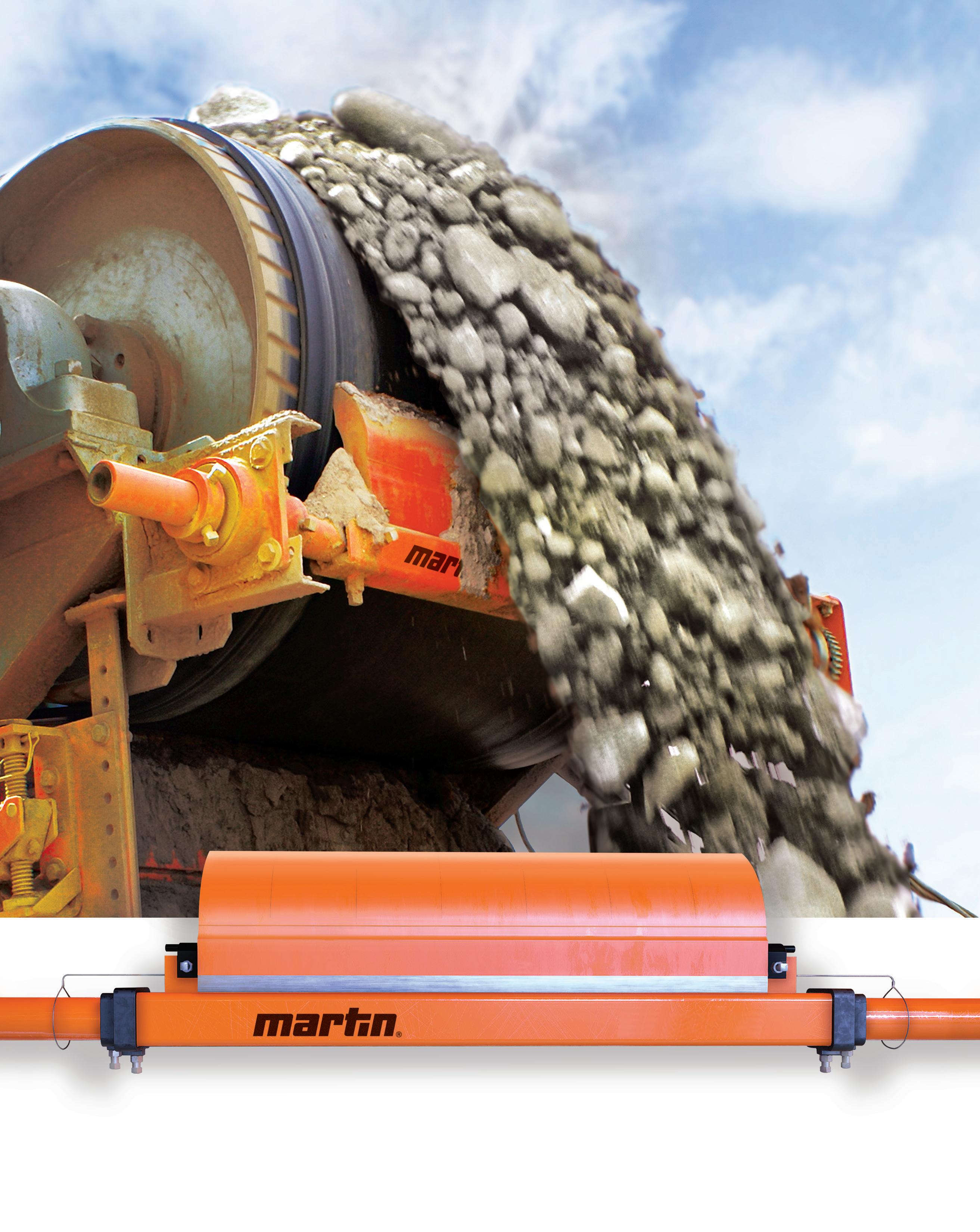
artin’s family of QC1+™ primary belt cleaners deliver industry-leading performance for the most demanding cement processing operations worldwide. These cleaners effectively discharge tough material from the belt, minimizing carryback that can lead to belt damage, component failure, higher costs for cleanup, and diminished production.
Featuring Martin's patented Continuous Angle Radial Pressure blade-to-belt technology, our application-specific urethane blade formulations, rugged mainframe construction, and easy blade replacement design, the innovative QC1+ maximizes cleaning effectiveness for all belt sizes and speeds.
QC1+™ HD
Focusing optimisation efforts solely on the loading process will not have the desired positive impact. The loading process itself also adds complexity, with different loading scenarios and specific challenges that must be taken into consideration.
Loading and unloading scenarios in cement plants
Cement plants typically have to support a wide range of loading and unloading scenarios.
f The most common use case is silo loading, with trucks or rail wagons, requiring high precision, reliable weighing, and fast throughput.
f Another important scenario is palletised loading of cement bags using forklift trucks.
This process is complex due to manual handling, pallet management, and coordination between drivers and forklift operators.
f Direct bag loading enables packed goods to be loaded directly without intermediate pallet handling, but also requires a deep integration between packing and loading systems and the logistic workflow.
f Unloading workflows (inbound processes) handle raw bulk materials such as clinker, gypsum, slag, or alternative fuels often requiring material identification and additional quality checks.
Typical challenges in loading and unloading workflows
Despite their importance, loading and unloading processes are often still associated with high manual efforts and poorly integrated processes, accompanied by excessive paperwork:
f Operators supervise multiple loading stations simultaneously, increasing the risk of errors and safety incidents. Weighing data is sometimes transferred manually or not fully integrated into delivery workflow.
f Uncontrolled vehicle movements frequently lead to traffic jams, long waiting times, and inefficient use of yard space.
f The number of deliveries per day is constantly rising thereby requiring a higher throughput, most of the time with the same infrastructure. But continuous availability (up to 24/7) is difficult to achieve when processes rely heavily on manual intervention.
f At the same time, plants should support – as outlined above – multiple loading and unloading scenarios with one system, rather than maintaining separate island solutions causing high complexity, higher handling efforts and lower efficiency.
How loading automation addresses these challenges
It is clear now that the loading process is influenced by all steps of the logistics workflow. Therefore, the order taking and planning process must be seamlessly integrated into the plant’s logistics workflow to ensure an optimised loading process. What such an end-to-end workflow might look like is explained below using Axians’ VAS Cloud Logistics and VAS Yard Management as examples.
Step 1: centralised order taking and order and transport planning processes
A central success factor for efficient dispatch operations is accurate pre-planning. Central order taking and planning solutions like VAS Cloud Logistics enable all relevant stakeholders (customer, dispatcher, and carrier) – to be actively
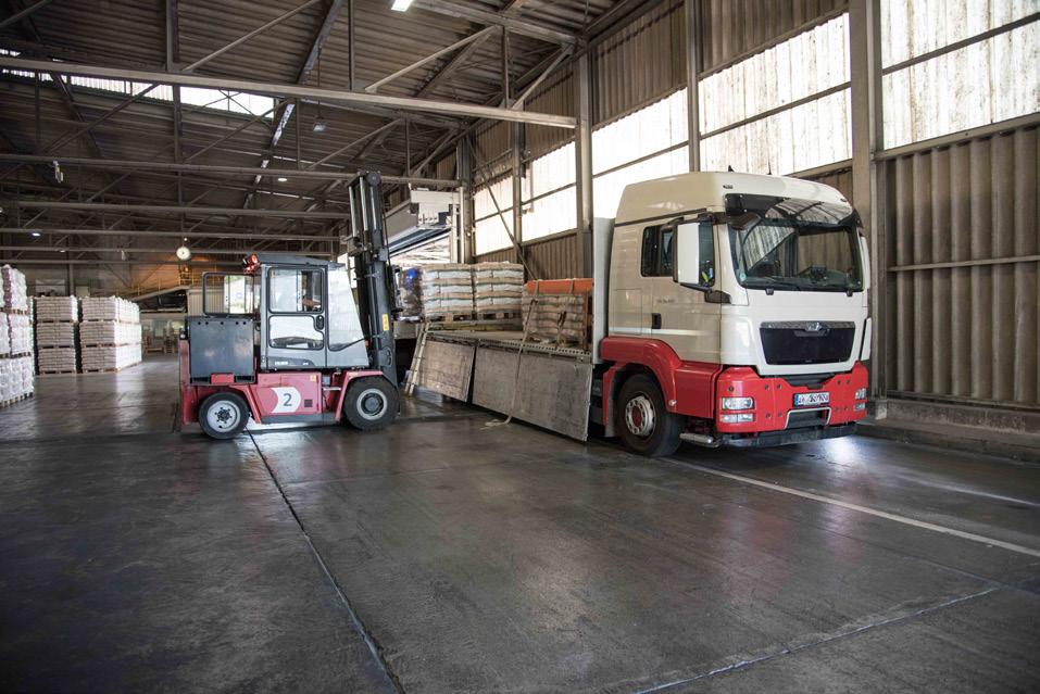
Cement bag loading with forklift trucks.
VAS loading terminal.
involved in the order process e.g. by placing orders independently 24/7, defining the required materials and quantities, and booking loading slots in advance. Automated transfer of relevant data between all involved parties further streamlines the process by eliminating delays and miscommunications. Preparation for plant check-in can be simplified by providing the driver with tools for a quick check-in (e.g. QR code or TANs).
Step 2: time slot management
Waiting lists and slot management reduce traffic congestion and waiting times at the plant. By creating digital end-to-end workflows, e.g. with VAS Cloud Logistics and Yard Management, customers or carriers can pre-book loading timeslots. This provides planning security and improves on-time deliveries, as customers and carriers arrive and load just-in-time.
Step 3: driver self-service check-in
But this preparation would be useless if the plant check-in process was manual, slow, and error prone. Thankfully the check-in process can be easily automated with a solution like VAS Yard Management and driver Self-Service Terminals. The Self-Service Terminals do not only provide a 24/7 availability, they also accelerate the process and eliminate miscommunication and errors:
f Drivers can authenticate themselves using various identification methods like QR-Codes or automated number plate recognition, reducing check-in times and eliminating manual verification.
f The driver can directly perform the entry weighing via a connected weighbridge, which automatically transfers the weighing data to VAS Yard Management.
f The ‘best-fit’ loading station is automatically assigned based on configurable rules like current stock levels or product availability.
To assign the loading station with regards to the actual loading capacities, the yard management system should be integrated with the leading ERP or warehousing system. Otherwise, an error-prone ‘double bookkeeping’ must be maintained across both systems.
Step 4: administrated loading station access
When the truck has checked in at the plant, it can directly proceed to the loading station, or pass through additional checkpoints that ensure that the time spent directly at the loading station is minimised, increasing the loading station’s capacity:
f A ‘loading station pre-check-in station’, where the driver has to perform and confirm all preparation tasks, like opening the tank manlid, before proceeding to the loading station.
f Administration of a local waiting list directly at the loading station.
Step 5: automate the loading process
As described above, the loading process itself is complex and requires, depending on the material or the loading method, different approaches for automation:
Step 5.1: automated silo loading
By connecting silo PLCs to VAS self-service terminals at the silo, drivers can control the silo loading process autonomously. This removes the need for permanent operator support and enables true 24/7 operation:
The truck driver can position the silo’s loading spout independently, start the loading process by himself and can constantly monitor the progress on the terminal – a perfect example of IT/OT integration in the cement logistics workflow.
Step 5.2: precise loading quantity control
Starting the loading process autonomously is one thing, automatically controlling the loaded quantity without manual intervention to avoid over- or underloading is a different story. VAS Yard Management permanently monitors and controls the loaded quantity and automatically adjusts the flow rate according to fineflow settings. Configurable backlash settings in VAS ensure a precise loading quantity by dynamically calculating the time to stop the flow.
Step 5.3: direct bag loading
Direct bag loading can also be fully automated through the integration of self-service terminals, the yard management system and the PLC, eliminating the need for manual handling processes. The yard management system can start the loading process, control the number of bags to be loaded, the ‘loading pattern’ (how the bags are arranged on the loading area), and the load securing check.
Step 5.4: Forklift truck loading
For scenarios with forklift loading, mobile loading terminals provide a highly efficient solution. Fully integrated with the yard management system, they eliminate paperwork and ensure real-time data capture.
The forklift truck is provided with an overview of all planned deliveries including delivery details. Additional functions such as pallet handling, batch tracking, and connections to packaging machines can be integrated seamlessly.
Step 6: ready for check-out
The lion´s share is done. The loading process itself and all preceding planning and coordination tasks are automated and optimised.
But the check-out should not be overlooked, as it offers optimisation potential in conjunction with loading. Exit weighing and delivery note creation can take place directly at the silo loading station, preventing congestion at plant exit.
In any case, online weighbridge connection and paperless delivery document creation are crucial for seamless delivery processes.
Operational results and business benefits
The impact of loading automation is clearly measurable. Manual effort and dependency on skilled workers are significantly reduced, while process reliability increases through tight IT and OT integration. Supporting multiple use cases with one system becomes a competitive advantage and directly improves customer satisfaction.
Faster throughput times lead to lower waiting times and reduced transport costs.
The elimination of paperwork saves time, improves data quality and traceability and reduces the carbon footprint. Overall, cement plants achieve higher efficiency, better asset utilisation, and improved profitability.
Outlook: loading reloaded
Loading automation will continue to evolve. AI will support process analysis and optimisation by identifying patterns and improvement potential across large volumes of logistics data. Driver self-service will move to mobile devices, enabling even more flexible and user-friendly interaction at the plant.
For cement producers, loading is no longer just an operational necessity. With the right digital foundation, like the VAS solutions from Axians, it becomes a strategic lever for competitiveness in an increasingly demanding market environment.
VAS Mobile Terminal on forklift truck.
Dr. Michail Akritopoulos and Dr. Tahir Abbas, Cinar, examine how advanced combustion modelling tools are helping cement plants increase their use of alternative fuels while maintaining clinker output and reducing emissions.
lternative fuel (AF) co-firing in the cement industry is on the increase, as new technologies, recycling processes, and incentives are driving the preparation of a wide range of fuel streams with varying thermal and physical properties. Some of these are seasonal, whereas others are in short supply, making it a constant challenge for a plant to switch to them in the most economical, less polluting, and operation-friendly manner.
Modelling-based specifications and technologies have assisted cement plants in increasing the thermal substitution rate (TSR) of AF, with TSRs up to 100%.1 The EU’s average TSR is over 50%, with considerable variation; similar values have also been reported in Asian and northern European countries.2 In the US, these values are, however, lower (16 – 25%) – but are improving and catching up with the EU and other
developed countries. At the same pace, mathematical modelling tools based on the mineral interactive computational fluid dynamics have been developed to reasonably accurate levels and are playing an essential role in the planning, permitting, feeding, firing, and emission reduction stages of AF utilisation. Some examples of interest from selected case studies are cited below.
Co-firing AF in a cement plant
The use of AFs, when optimised, provides an attractive option for lowering energy costs and has been one of the prioritised goals of most cement producers. However, the co-processing of AF by the cement industry needs to be analysed for each specific
application, in particular to mitigate the following adverse effects:
f Loss of clinker output.
f Higher heat consumption (kcal/kg clinker).
f Capital costs for pre- and co-processing of AF’s.
f ‘Build-up’ and an increase in kiln instability phases.
f Increased emissions (usually CO, hydrocarbons).
f AF’s lower thermal substitution rates impede clinker production to justify investment.
The economics of firing AFs also very much depend on the local conditions; for example, the availability of the type of AF and ‘sold-out’ or ‘surplus’ cement market conditions. However, even when the market is ‘surplus’, the plant needs to operate near maximum clinker output when it is producing, due to the needs of operational efficiency. When the market is ‘sold-out’, any loss in clinker output would have a significant negative impact on plant profitability.
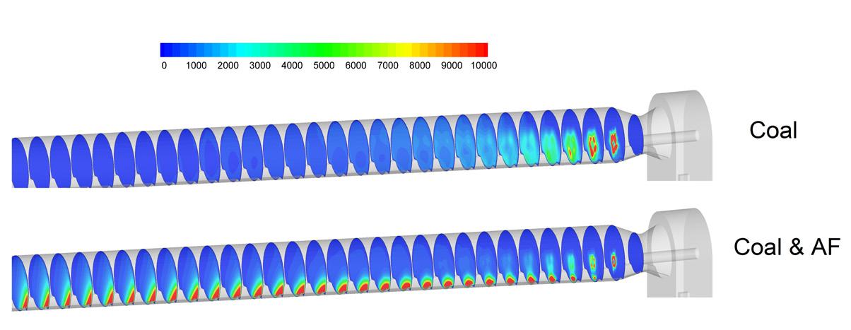
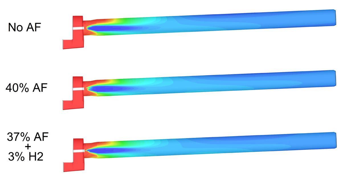
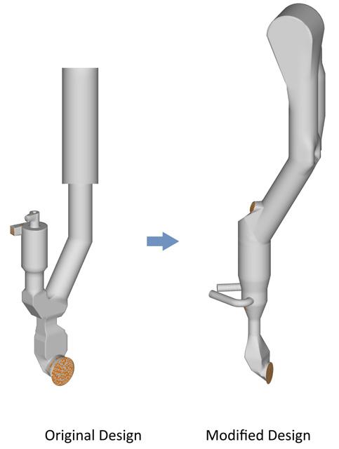
2. Reaction zone starts earlier as lower oxygen concentrations (blue colour) move closer to the burner tip: without AF cofiring, with 40% AF cofiring and 40% AF cofiring including 3% H2 in the AF mix (from top).
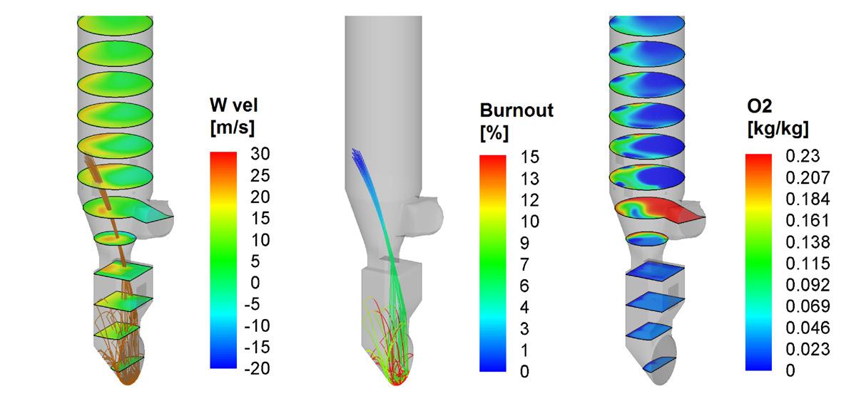
3. MI-CFD results in an inline calciner: (left) upward velocity profiles with tyre chip trajectories, (centre) evolution of tyre chips combustion, and (right) oxygen profiles.
There are several long and tedious steps prior to AF utilisation, including AF market potential, permitting, handling, storage, feeding, and finally adapting to the best combustion and emissions strategies. The latter aspects are discussed in more detail later in this article with a brief analysis relating to the suitability of the AF and its economic aspects.
AF co-firing potential
What is required to increase AF substitution in the kiln burner?
When millimetre-sized AF chips (30 x 30 mm 2-D chips) were co-fired with coal (20% TSR), a large fraction of AF fell on the kiln bed after partially burning under gravity, thereby producing localised fuel-rich conditions. This led to higher CO and SO2-driven volatile cycles, causing kiln instabilities and affecting clinker quality. During the AF trials at the plant, the CO emissions at the kiln back-end increased by 20 times (Figure 1), mainly due to heavier fractions of AFs falling at the kiln feed and burning therein under oxygen-lean conditions, thereby generating high CO (2000 ppm).
To overcome the higher CO emissions and increase the AF substitution, the plant has limited choices, either substantially reduce chip size (from mm to µm) or switch to another solid or liquid fuel, both of which, in most cases, are uneconomical. Major modifications to the kiln burner
Figure 1. CO emissions increased when AF was co-fired with coal through the main burner.
Figure
Figure
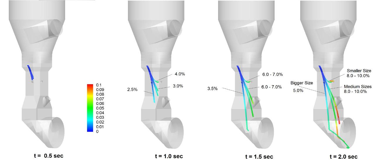
Figure 4. MI-CFD results in an Inline Calciner fed with tyre chips, show tyre chip trajectories at discrete time intervals (t= 0.5, 1.0, 1.5, and 2.0 sec.) as they fall towards the kiln hearth. The colour of the trajectory represents the burnout fraction with burnout for larger chips that fall to the kiln hearth at 5% with medium even reaching at ~10% before reaching the kiln hearth.
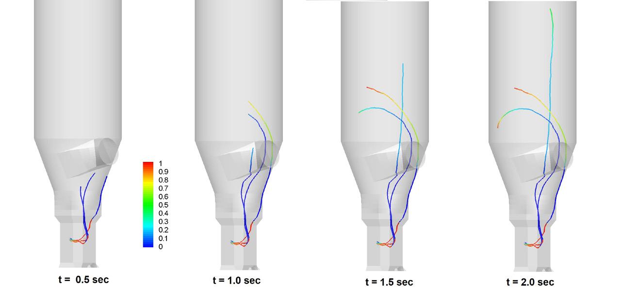
Figure 5. MI-CFD results in a similar inline calciner showing coal particles at similar time intervals. The colour of the trajectory represents the burnout fraction, but the legend is different from Figure 3, with red representing full burnout, and the particles show a more detailed burnout where the release of the volatiles happens in the first 0.5 sec., and then the colour goes again from blue to red, representing the burnout of the remaining char.
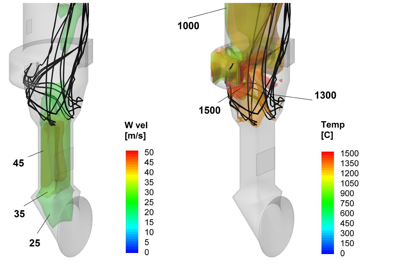
6a. Light fluff material (black colour), wholly suspended, is shown interposed on iso-surfaces of vertical component of velocity (left) and temperature (right).
were again out of scope; the CO oxidation through higher momentum cold air injection comes with a loss of energy efficiency, hence was ruled out. The plant, therefore, opted for a combination of those techniques which would promote the earlier ignition of AF chips and drive fuel volatiles out, i.e., satellite burner, or a small amount (2 – 3%) of co-firing a higher reactivity combustion enhancer, i.e., H2 The latter option is promising as it also has a slight positive effect of reducing CO2 emissions. Figure 2 shows that higher reactivity H2 instantly ignites and consumes prevailing oxygen near the burner axis, which in turn provides an ignition source to adjacent AF fractions. The same effect has also been reported in other independent studies where hydrogen acted as a combustion enhancer for the AFs.
Increasing AFR in the calciner Calciners offer better opportunities to fire AFs as compared with the kiln, with the possibility of multiple ports and the provision of firing higher size/density solids, mostly uplifted by the upward gas flow, burning in suspension mode. The fuel injection location(s) relative to the tertiary air and meal inlets in the calciner are of paramount importance. The fuel burnout and calcination levels could be enhanced without adversely affecting the hot-spots, kiln stability or emissions (VOCs, CO, and NO) by optimising the location and injection strategies for fuel and meal, which can vary from plant to plant. To optimise a calciner originally designed for pulverised fuel firing for AFs, detailed information on all important variables of combustion, process, and emissions is required. However, this is mostly unachievable due to the harsh combustion environment. For example, gas
Figure
Figure 6b. Hot meal particles are shown interposed on iso-surfaces of temperature profiles (from only one inlet (left) and split into two inlets (right) to curb the excessive temperature regions).
Figure 7. A calciner modification can: (left) Extend the residence time from 1.5 sec. to 5.0 sec. (right) Redesign an RSP-type calciner to its in-line version with a similar residence time (the X5-TEQ by PMT).
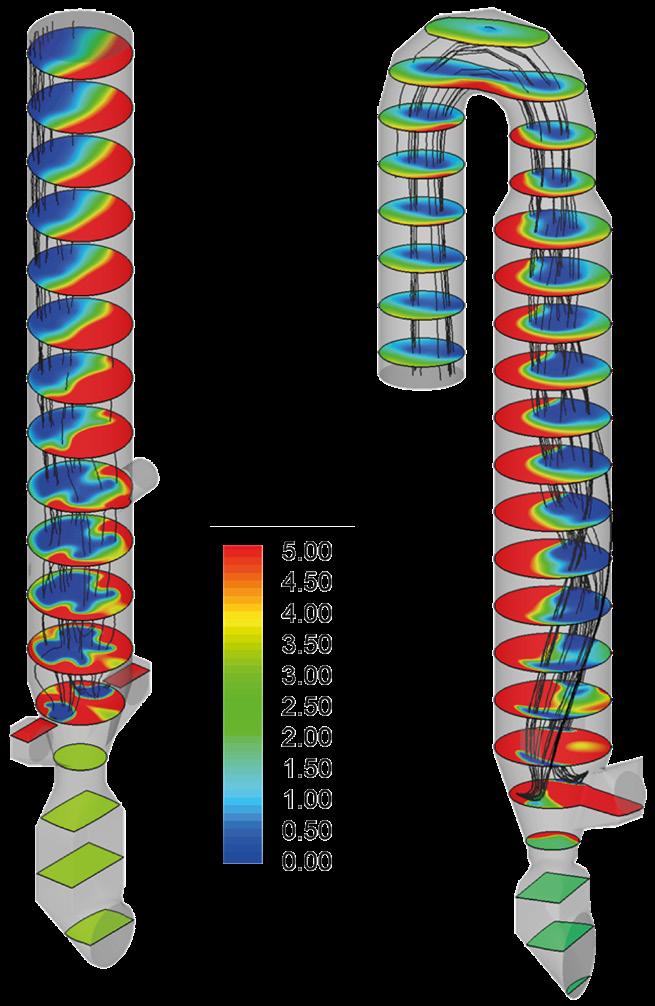
Figure 8. Coal particle trajectories in 3D oxygen concentrations (radial segments) below 5% (0%: blue colour 5% red colour) (left) Case with three TA inlets (right) Calciner with one TA.
flow velocities increase with the intensity of heat release, and the level of burnout and calcination of fuel and meal particles cannot be traced from the point of injection to the calciner exit. This is because turbulence strongly influences flow trajectories through dispersion, diffusion, and even rotational and stagnation phases. Hence, the required data is generated by integrating non-linear reactions and computing them through advanced mathematical models, in which the above-mentioned variables are taken into account.
How TSR can be enhanced in calciners In calciners, uniform and well-mixed kiln gas flow partly accelerates upon entering the calciner, through the kiln inlet bend, where it changes direction and flow velocities become higher towards the back wall. The opposite side (kiln side) of the calciner experiences lower velocities or even reverse flow as the momentum is preserved. For example, Figure 3 shows the predicted results for an inline calciner fired with heavy AF (tyre chips). At the kiln inlet (Figure 3a), as the kiln combustion products enter the smoke chamber, more gas flow is shifted towards the back wall; in consequence, a lower velocity region forms towards the front wall (kiln side). This stratified flow persists into the narrow riser duct for all types of fuels and calciners. In inline calciners, depending on the flow angle of the tertiary air stream(s), the developed higher/lower gas velocity regions are somewhat shifted again. Flow from the tertiary air occupies most of the lower velocity front-end region as well as a portion of the adjacent back-wall segment, thereby slightly moving the higher velocity regions anticlockwise (as per top view). As a result, higher velocity regions move from the back-wall towards the calciner sidewall – hence heavier AF chips may not be levitated if passing through the lower velocity segments at the opposite side and move away the higher oxygen regions created by the TA injection (Figure 3c).
The tyre-chip trajectories show that, although tyre chips were initially introduced into the region of higher upward gas velocity, chip momentum quickly carries them away from this region into the lower upward gas velocity zone. As previously shown, tyre chips confined to the lower upward gas velocity region of the riser duct experience only about 15 – 20% burnout (Figure 3b) before landing onto the kiln hearth. Semi-burnt chips continue burning but at a much slower rate in the kiln hearth area after mixing into the bed material. This restricts the substitution of tyre chips due to much less chip surface area coming into contact with oxygen and leads to higher carbon in the meal proportion, which in turn drives the sulfur cycle by decomposing the formed CaSO4 when temperatures increase at the end of the calcination zone.
A small to moderate improvement in tyre chip burnout can be achieved by adjusting their injection angle so that their trajectories are kept within the higher upwards gas velocity regions. Further burnout improvement can be secured through the installation of a venturi-type ‘refractory-bump’ in the region of the chips trajectories to give rise to gas velocities in the range of 40 – 45 m/s over a distance of 2 – 3 m. The typical venturi solution results in a 0.5 to 1.0 mbar pressure loss, which is compensated by a higher TSR of tyre-chips as well as a reduced need for air-blasting. The latter is minimised because the improved tyre chip burnout within the calciner reduces the ‘carbon in hot-meal’, eliminating frequent build-ups in the calciner.
In Figure 4, in a similar type calciner with tyre chips injection, the detailed view of the falling tyre chips trajectories evolution reveals their fate as they fall towards the kiln hearth. In the absence of a venturi-type ‘refractory-bump’, bigger chips that fall under gravity are difficult to suspend in the kiln riser. Bigger to medium chips arrive at the bottom of the kiln hearth within 2 sec., reaching a burnout varying from 5 to 10%. Subsequently, an adequately designed venturi restriction slows down their falling through and manages to suspend some of them so that they eventually fall towards the kiln hearth with higher burnout. Comparatively, Figure 5 shows the combustion progress of a pulverised fossil fuel fired from a simple burner.
The fuel quickly devolatilises, releasing all volatiles, and is then carried upwards with the kiln gases, leaving only the char. Complete (100%) burnout is achieved in suspension at higher locations.
For the lower-density solid AF, it is essential to ignite chips and oxide in higher oxygen regions as these may exit the calciner without fully burning (Figure 6a). When a calciner is designed or modified such that the chips trajectories and the required upward gas velocities combine to ensure upward entrainment of the solid AF and its burnout within the suspension mode, both CO and NO emissions remain low. With increasing AF throughput, the combustion reaction zone eventually shifts, requiring meal diversion to the higher-temperature regions. Hot-spots near the calciner walls can be eliminated through splitting the meal feed into two and directing meal to higher temperature regions (Figure 6b).
In addition, when introducing lower density AF (e.g., ‘fluff’), it is important to design the AF inlet(s) so that chips/particles of the material are not trapped in lower velocity regions, in particular in re-circulation zones, as entrapped unburnt fuel volatiles increase CO formation.
The maximum AF substitution that can be realised
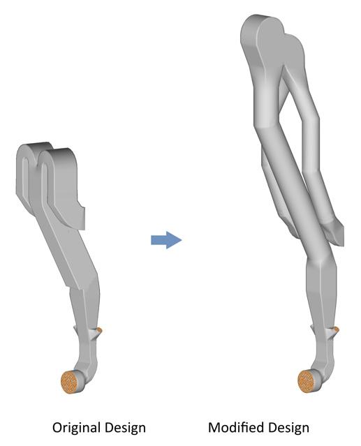
Higher substitution of AFs requires low-capex solutions without negatively affecting clinker production or emissions. For increasing the throughput of AF, mathematical modelling input is essential from all planning stages, i.e., selection of AF characteristics, dosing type, and injection strategies for the best return on the investment, as well as lowering the carbon footprint. For example, for a 100% AF substitution rate, a shorter-residence-time calciner needed an upgrade from 1.5 to ~5.0 sec., whereas an RSP (reinforced suspension preheater) calciner configuration was modified to an inline configuration, yielding a similar residence time (Figure 7).
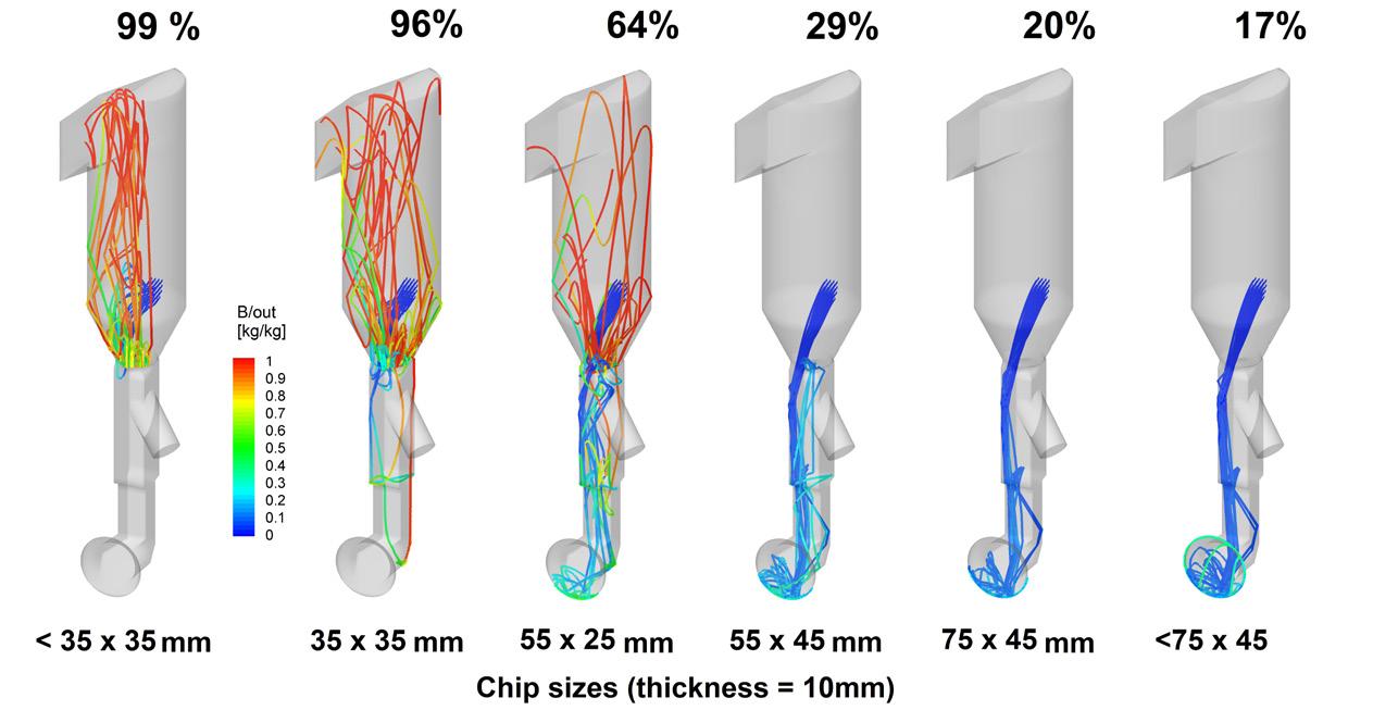
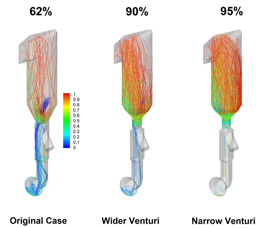
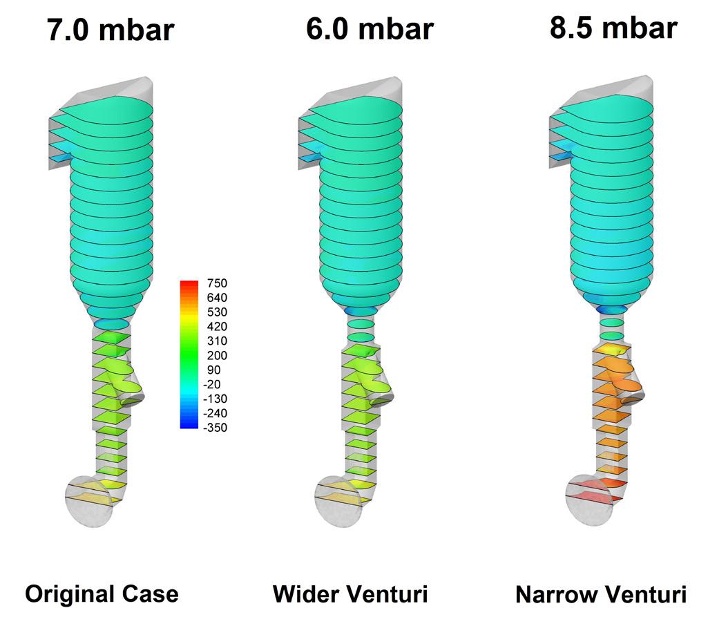
Figure 8 shows the coal particle trajectories travelling in regions of oxygen concentrations below 5% (regions 5% or above are in red colour), showing the effect of flow stratification. An example of a higher CAPEX solution would be to split the tertiary air so that the coal particles can be burnt earlier within the calciner in higher oxygen regions (Figure 6a). However, a more cost-effective solution can be realised with the assistance of modelling by splitting coal through additional burner(s) and divert coal particles to higher oxygen regions, hence keeping a single tertiary air duct but incorporating two additional coal burners. Combustion interactive process modelling assists during all stages of AF firing projects, from its source specifications to its feeding and substitution rate. Figure 9, for example, shows results of a detailed MI-CFD study of a narrow duct restriction (i.e., throat-restriction) which has been a typical design feature of several classical calciner designs, built in the latter part of the last century, experiencing excessive pressure drop but proving ineffective in suspending heavier and larger-sized fuel chips. The solution to increase TSR was to remove the restriction and replace it with a venturi-type throat producing localised higher velocities, as shown in Figure 10. The higher-pressure loss design (Narrow Venturi) allowed for an increase
Figure 9. Fuel chips (of 10 mm thickness) injected in a calciner with a throat restriction that suspends only smaller fractions (sizes are shown in increased order from left to right) but allows some medium (middle) and all the larger sizes (right) to fall to kiln hearth.
in tyre-chip burnout from 62 to 95%, whereas a low-pressure loss design (Wider Venturi) (while still maintaining a pressure loss slightly lower than that in the original design) increased the tyre-chip burnout from 62 to 90%.
Recent and future advancements in the modelling techniques
With the advances in computational power and data-driven methods, machine learning (ML) combustion and process modelling of complex reactions is improving. The main hurdles to benefit from the latest technologies are the complexities of the turbulence under reacting flows, making it difficult to acquire reliable and consistent data. Therefore, the emphasis has been placed on the integration of these reduced chemical mechanisms, e.g., calcination, CO, NOx. These sub-models have also benefited
Figure 10. Among several suggested designs, two have significantly increased the suspension of falling tyre-chips and thus their burnout. Wider Venturi Case is preferable as it is not increasing the pressure drop as the Narrow Venturi Case.
from the increased use of the parallel processing technique. The traditional use of physical modelling of a kiln and calciner was found helpful in visualising the transit conditions related to flow and mixing, which can now be simulated using computational fluid dynamics, using enormous computational power, i.e., using parallel processing. However, without specific numerical values as quantitative indicators, this approach effectively reverts to physical modelling, saving only some of the cost and time associated with constructing a scaled Perspex model of the geometry of interest (kiln or calciner).
The use of AI has found its place in many industries and is today promoted as a must-adopt tool; however, its effectiveness depends on reliable, consistent data. Without unambiguous, diverse data sets, AI struggles to deliver accurate or realistic results, which means poor data would lead to poor predictions, as experience shows that 85% of AI projects fail due to data issues.2 However, the data required can be generated using detailed combustion and process interactive models, as described above, followed by the use of AI in the generation of control and maintenance strategies, a promising and developing area of active research.
Conclusion
Advanced mathematical tools these days are playing a pivotal role in all AF substation projects. From AF properties to its dosing, injection locations, TSR, and required kiln and calciner modifications. The use of AF, with a lower carbon-to-hydrogen ratio, not only reduces CO2 emissions but is also an inexpensive source of thermal input.
The advent of computational power and upcoming AI and ML techniques in the near future will provide further impetus for the combustion interactive process models. However, at present, greater emphasis is required to obtain meaningful insights into the implementation of scenarios that provide detailed and reliable solutions, particularly for the thermal substitution of AFs. In the presented modelling results, advanced sub-models for AF were employed where necessary, including those addressing the combustion of larger and irregular chips. Specifically, a new ‘layer-by-layer’ combustion modelling approach was used, in which a chip is divided into a finite number of layers, and the combustion of one layer triggers the devolatilisation of the subsequent layers.
References
1. AKRITIOPOULOS, M., & ABBAS, T., 'Marvels of MI-CFD Mechanics (for optimizing AF use)', WorldCement , April 2025, pp 79 – 85
2. 'Alternative Fuels: Where Next?' – https:// cementproducts.com/2025/02/10/alternative-fuelswhere-next
on thermal
CE Thermal Vision Technology, explains how the effective use of thermal imaging demands a fundamental rethinking of how manufacturers approach total cost of ownership, data integration, and workforce development.
he cement industry stands at a critical inflection point in its digital transformation journey. After years of experimental deployments and pilot projects, thermal imaging technology has transitioned from an optional diagnostic tool into essential infrastructure for production optimisation, safety management, and carbon compliance. However, as the sector discovered throughout 2025 and early 2026, successful implementation requires far more than hardware installation – it demands a fundamental rethinking of how manufacturers approach total cost of ownership, data integration, and workforce development.
The economic tipping point
The technological and economic landscape shifted dramatically between 2020 and 2025. Domestic non-cooled infrared detectors achieved performance levels (NETD <50 mK) that match international standards while offering cost advantages of 30 – 50% compared to imported alternatives. More significantly, thermal imaging module costs have declined over 60% during this five-year period, driven by advances in 12 μm wafer-level packaging and manufacturing yield rates exceeding 95%.
This cost compression, combined with increasingly stringent regulatory requirements under China's dual-carbon policy framework, has transformed thermal imaging from a ‘nice-to-have’ technology into a strategic necessity. The Implementation Plan for Carbon Peak in the Building Materials Industry has created rigid constraints on energy consumption and emissions, pushing cement manufacturers to seek every available efficiency gain.
Yet the market narrative has evolved beyond simple adoption metrics. According to recent industry sentiment analysis, 42% of professional discussions now centre on ‘application effectiveness evaluation’ and ‘investment implementation reviews’ – a clear signal that the sector has moved past the question of whether to deploy thermal imaging and is now grappling with how to extract maximum value from these systems.
Three-dimensional value proposition
Modern thermal imaging applications in cement plants serve three interconnected functions, each addressing distinct operational and strategic imperatives.
Safety and reliability enhancement
Continuous 24/7 monitoring of rotary kiln shells, refractory linings, and critical auxiliary equipment fundamentally changes maintenance paradigms. Traditional manual inspection methods, dependent on worker experience and physically limited by hazardous high-temperature environments, miss developing problems that thermal cameras detect weeks in advance. Industry case studies demonstrate that predictive maintenance enabled by thermal monitoring can reduce unplanned downtime by 30 – 50%.
The tragic October 2025 mechanical injury accident at a Huarun Cement facility, resulting in one fatality and direct economic losses of approximately 2.875 million RMB, served as a stark reminder of these limitations. In the accident's aftermath, safety-related discussion volume surged 280%, accelerating adoption decisions across the sector.
Process optimisation and energy efficiency
The evolution from fault detection to process optimisation represents thermal imaging's most significant value expansion. Real-time, full-coverage temperature field data from kiln systems enables
AI-driven combustion optimisation that stabilises the calcination zone and reduces standard coal consumption per t of clinker by 1.5 – 3%.
More importantly, optimised combustion directly contributes to NOx emissions reduction of 25 – 40%, as documented in multiple operational deployments. One leading manufacturer reported that by precisely controlling flame shape and temperature distribution through thermal feedback, they achieved gas savings that delivered ROI within two years while simultaneously meeting tightening environmental standards.
Carbon compliance and asset creation
Perhaps the most forward-looking application involves integrating thermal imaging data into carbon accounting systems. Continuous, precise temperature and combustion efficiency data provides high-quality inputs for calculating process carbon emission factors. As carbon markets mature and reporting requirements become more granular, this capability transforms from an ancillary benefit into a strategic asset.
Early pilot projects are exploring how thermal monitoring data can support carbon quota allocation verification and even contribute to tradeable carbon credits. At current carbon prices (approximately 80 RMB/t), the annualised carbon asset value from thermal optimisation at a 5000 tpd production line could reach several million RMB – a figure that must be incorporated into investment evaluation models.
The hidden cost challenge
While hardware prices have declined significantly, total cost of ownership tells a more complex story. Field implementation reviews reveal that hidden costs typically represent 30 – 50% of total investment, far exceeding initial hardware budgets.
These costs break down into three categories:
f Engineering implementation (22% of hardware cost). Industrial-grade network cabling, explosion-proof electrical installations, mounting structures for high-temperature environments, and civil works for equipment placement all require specialised expertise and materials that suppliers' initial quotes often don't fully capture.
f System integration (15% of hardware cost).
Connecting thermal imaging data to existing DCS (Distributed Control Systems), MES (Manufacturing Execution Systems), and energy management platforms requires custom interface development, protocol conversion middleware, and extensive commissioning. The lack of standardised data protocols – despite growing advocacy for OPC UA adoption – means each integration project becomes a bespoke engineering effort.
f Long-term operations (5 – 10% annually).
Lens window cleaning in dusty cement plant environments, periodic calibration, software updates, and most critically, expert data analysis
require ongoing investment. Many plants discover that without personnel who understand both thermal imaging principles and cement production processes, sophisticated systems degrade into simple over-temperature alarms, leaving most value unrealised.
A production manager at a mid-sized facility shared this cautionary tale: "Our supplier quoted 800 000 RMB for hardware. By the time we finished network upgrades, explosion-proof enclosures, and DCS integration, we'd spent 1.2 million. The real shock came six months later when we realised our maintenance team couldn't interpret the thermal data beyond basic alarms. We're now paying 150 000 annually for remote analysis services that should have been budgeted from day one."
The data integration imperative
The industry's most pressing technical challenge is not sensor performance – it is the ‘soft data silo’ problem. Thermal imaging systems that operate in isolation, unable to feed their rich data streams into broader plant intelligence platforms, deliver only a fraction of their potential value.
Leading cement groups have invested heavily in data middleware and unified industrial IoT platforms that enable thermal data to interact with vibration monitoring, gas analysis, and process parameters. This fusion allows AI models to correlate subtle
temperature variations with equipment degradation patterns, predict kiln refractory life with unprecedented accuracy, and automatically adjust combustion parameters for optimal efficiency.
However, these deep integration projects demand substantial IT/OT (information technology/operational technology) convergence capabilities that remain beyond reach for many smaller manufacturers. The solution gap is driving innovation in business models, with several vendors now offering cloud-based SaaS platforms where edge devices perform basic processing locally, while complex AI analysis happens remotely. Subscription-based pricing (under 200 000 RMB/yr for comprehensive monitoring) lowers entry barriers while transferring integration complexity to specialists.
Dual-track market dynamics
The supplier landscape reflects a clear bifurcation between application tiers. International brands like FLIR maintain strong positions in mission-critical applications – particularly in-kiln flame analysis where extreme temperatures, dynamic ranges, and long-term reliability requirements justify premium pricing. Their decades of accumulated process models and global reference cases provide the ‘certainty premium’ that risk-averse chief engineers seek for core production systems.
Meanwhile, domestic suppliers including Hikvision, Dali Technology, and others have achieved strong
market penetration in auxiliary equipment monitoring and plant retrofit projects. Their advantages extend beyond 30 – 50% cost savings to include rapid local service response, flexible customisation, and increasingly open data interfaces that ease integration burdens.
This competitive dynamic is driving sector-wide transformation from product sales to value delivery models. Performance-based contracts – where vendors guarantee minimum energy savings or share in efficiency gains – are emerging as risk-mitigation mechanisms, though standardised measurement protocols remain underdeveloped.
The workforce transformation paradox
Technology adoption confronts a profound human capital challenge. Extracting value from thermal imaging systems requires personnel who bridge cement production expertise with data analysis capabilities – a rare combination. Industry estimates suggest a shortage rate exceeding 70% for these ‘translator’ roles.
The social dimension extends beyond skills gaps to employment anxiety. Automated monitoring systems demonstrably reduce traditional inspection staffing requirements. One facility reported reducing its patrol team from 12 to 3 workers after full deployment. For affected employees – often mid-career workers with decades of hands-on experience but limited formal education – the prospect of retraining as ‘data analysts’ generates significant stress.
Progressive manufacturers are designing ‘just transition’ programmes that include systematic reskilling, new position creation (such as remote diagnostic support roles), and salary adjustments that recognise evolved responsibilities. These initiatives are not merely social responsibility measures – they are operational necessities. Plants that neglect workforce adaptation discover that unengaged or anxious employees can sabotage sophisticated systems through simple non-cooperation.
Looking forward: AI competition and carbon integration
The next competitive frontier lies in AI algorithm sophistication and industry-specific process models. As hardware performance converges, vendors are racing to develop fault pattern libraries that can distinguish between dozens of kiln abnormalities – coating rings, refractory spalling, feed material inhomogeneity – with diagnostic accuracy approaching expert human judgment. More transformatively, thermal imaging data's integration into carbon accounting systems will likely become standardised within 1 – 2 years. Regulatory frameworks for using continuous thermal monitoring to verify emission reduction claims are currently in pilot phases. Once established, this
capability will shift thermal imaging from the cost centre of equipment maintenance budgets into the value centre of corporate carbon strategy.
Recommendations for successful implementation
Based on documented case studies and industry feedback, manufacturers should:
f Adopt Total Cost of Ownership models that explicitly budget for engineering work, system integration, and ongoing operations before procurement decisions.
f Demand open data interfaces and prioritise suppliers supporting standardised protocols (OPC UA) to future-proof integration capabilities.
f Invest in workforce development alongside hardware, creating clear career paths for operations staff transitioning into data-driven roles.
f Start strategically, then scale: Initial deployments at highest-risk or highest-value nodes (kiln systems, coolers) allow value demonstration before facility-wide expansion.
f Consider subscription models for smaller facilities where upfront CAPEX and integration complexity create prohibitive barriers.
The cement industry's thermal imaging journey has moved decisively beyond the ‘whether’ question to the ‘how’ challenge. Success in this value realisation phase will separate digital leaders – who achieve rapid ROI, meaningful emissions reductions, and enhanced operational resilience – from digital laggards for whom expensive systems become underutilised monitoring curiosities. The technology works; the differentiator is implementation excellence.
References
1. Industry sentiment analysis based on 12 000+ professional discussion threads and 500 000+ interactions across specialized forums, social media, and industry platforms (2025.10-2026.02).
2. Technical specifications and cost data: CE Thermal Vision, 'Industrial-Grade Thermal Imaging Solutions', – https://cethermal.com (Accessed February 2026).
3. Policy framework: 'Implementation Plan for Carbon Peak in the Building Materials Industry', National Development and Reform Commission, 2025
4. Technical standards: GB/T 25737-2025 'Monitoring System Acceptance Specifications', implemented November 2025.
5. Case study data compiled from cement industry publications, equipment vendor white papers, and field implementation reports (2025 – 2026).
Damien Michel and Thomas Lamare, CHOVET, explore how separate grinding can support the production of lower-carbon cements while improving flexibility in plant operations.
n the face of the climate emergency and the necessity to reduce the carbon footprint of the cement industry, separate grinding is emerging as a strategic technological lever. By grinding clinker and supplementary cementitious materials (SCMs) independently before blending them, it is now possible to optimise energy consumption,
reduce CO2 emissions, and better control cement performance. All of this can be done while relying on existing technologies that can be rapidly deployed.
In the short to mid-term, it appears as an effective solution compared to CAPEX-intensive and technologically-complex carbon capture projects.
CHOVET has been positioning itself for several years at the forefront of this shift toward decarbonising the cement industry, assisting several major cement suppliers. The company supports long-standing clients including Holcim (Lafarge France), Heidelberg Materials, CRH (Eqiom, Jura Cement), Vicat, Cem’In’Eu, Hoffman Green, F-SCOTT and, as well as newcomers, on a market diversifying with low-CO2 products.
What is separate grinding?
Separate grinding consists of grinding clinker and the other cement constituents
independently, before blending them in the required proportions for the final product.
It is fundamentally different from the standard and historical co-grinding approach, which involves mixing all components in the required amount into the finish mill to grind and mix them together.
Cement performance depends directly on the fineness and particle size distribution of its constituents. However, clinker is a very hard material and is particularly energy-intensive to grind, unlike other components that are often softer.
These MICs (mineral components) or SCMs depending if they are added to the clinker or the cement, include materials of various types and origins such as slag, fly ash, limestone, pozzolans, calcined or activated clay, construction demolition material, etc., they each have their own grindability, reactivity, and performance.
In a combined grinding process, the entire system is designed to meet the requirements of clinker, which can lead to excessive energy consumption and sometimes unnecessary overgrinding of the other materials.
In a separate grinding process, it is possible to optimise energy usage by reaching a precise and desired fineness for each constituent without excess.
The result: lower energy consumption, reduced CO2 emissions, and cement with more precisely controlled performance. It also allows a much higher flexibility of the grinding system which can adapt to various product formulas and quickly switch between different customers’ requirements (grades and volumes).
Old technologies... revamped
Proven and existing technologies from the cement industry, once considered outdated, are now returning to the forefront of industrial strategies. The main goal driving separate grinding projects is to reach the perfect product blend with the lowest environmental footprint. Historically, cement has been
Figure 1. 3D model inspired by real CHOVET studies.
Figure 2. Mass flows inspired by a real CHOVET study.
made in the mill. With separate grinding, it is now ‘made downstream’, during the blending of precisely controlled components.
The first major challenge for producers is to master blending technologies, a new strategic skill that is crucial for the final quality of the product. The second major challenge is increasing the fineness of clinker, which is essential to meet increasingly demanding specifications. The final objective is clear: more performance, less CO2.
A global solution for the construction sector
In a context where the cement industry accounts for around 6 – 8% of global CO2 emissions, the stakes are enormous. If the cement sector were a country, it would rank among the world’s largest emitters. Faced with this reality, the industry’s objective is clear: to bring this figure down to match the construction’s industry carbon reduction commitments.
The impact of separate grinding is considerable. By facilitating the production of large range of low-carbon cements, it helps preserve the competitiveness of concrete in complement or against materials perceived as more environmentally friendly, such as wood or certain bio-based solutions.
Adapting plants without getting trapped
While the promise is strong, it comes with several critical considerations for cement producers.
The first concern is strategic. Cement producers regularly adapt their product mix and develop new formulae to answer the market needs. Separate grinding requires the development of systems capable of rapidly adapting to constantly evolving products and requirements, driven both by market changes and CO2 reduction constraints. The second concern is operational. The challenge is not to start from scratch, but to transform existing production facilities at minimal cost, with a minimum time to market, while maintaining a high level of flexibility for future developments. Investments must meet current needs without locking the producer into a rigid configuration that would limit future adjustments in response to market evolution and carbon regulations. It is not the technology that should define the product, but rather the product – and therefore market needs – that should guide the technological choice. Clearly defining the expected cement portfolio characteristics is a key step toward selecting the most appropriate industrial solution.
Cement production demands equipment that keeps pace with intense daily operations. Alimak industrial elevators are engineered to support smoother plant workflows – helping teams reach critical areas faster, reduce time‑consuming climbs, and streamline maintenance routines. Built for tough, high‑dust environments, our elevator solutions contribute to improved uptime and more efficient task execution across your facility. Elevate productivity, enhance operational continuity, and keep your plant performing at its peak.
Challenges and opportunities: a demanding yet promising equation
The challenges of separate grinding are numerous: upskilling in blending, mastering fineness control, adapting facilities, and securing technological choices.
But the opportunities are just as significant. By enabling the production of lower-carbon cements, separate grinding opens the path toward a credible and industrially scalable decarbonisation of concrete. Throughout various projects, CHOVET was able to analyse different concepts and implementation strategies as shown in Figure 1.
Case study 1 – from co-grinding to flexible separate grinding
In a recent industrial project led by CHOVET, the initial objective was to replace several ‘small’ ball mills by a single vertical roller mill (VRM) and move toward a more efficient separate grinding scheme, where clinker and SCMs are processed independently and later blended on site. However, as the study progressed, a key limitation emerged: the VRM could not achieve the clinker fineness required to meet market performance expectations. As product requirements evolved, so did the industrial strategy. The project was therefore reoriented: abandonment of the VRM, elimination of multiple small mills, and adoption of a single large capacity ball mill better suited for the target fineness. SCMs, delivered pre-ground, are combined with the clinker base in a blending workshop, ensuring precise final composition. This case illustrates a fundamental reality of separate grinding: the solution must remain flexible, scalable, and driven by end-product requirements.
Case study 2 – optimised separate grinding and final blending strategy
In this case originally, the process consisted of a coarse pre-grinding stage followed by final
co-grinding of the base and additives, including mixing. After the site visit, it quickly became clear that the most effective solution would be to grind all MICs in a dedicated ball mill, while reserving the existing grinding line exclusively for clinker grinding (the base).
Only in a second step are all ingredients blended to achieve the final product composition.
Case study 3 – optimisation through separate grinding and controlled blending
Initially, the few ball mills operated in co-grinding mode, each producing finished cement from a clinker-additives mixture, with limited flexibility and variable performance. As part of the industrial optimisation approach, it was decided to specialise each piece of equipment: some mills were dedicated to grinding the clinker base, while others were assigned to grinding additives (MIC). The intermediate products obtained are then conveyed to a blending workshop. This setup allows a better control of fineness, quality, and cement formulation. The final configuration with dedicated mills for the base, others for MIC additives ensures more flexible and efficient production, while drastically limiting the overall CAPEX.
The separate grinding mindset
There is no standard ‘off-the-shelf’ strategy: each project is unique, given a specific product portfolio, an existing plant or equipment configuration, and the commercial strategy. Chovet’s experience helps to support clients, listen to their needs, and engage in dialogue to define the best solutions for each of their cement plant.
Different technologies can be applied, including ball mill, VRM, or roller press, again depending on the product type and integration on the cement plant. As such, the Chovet method aids in the successful implementation of separate grinding projects. It consists of thinking out of the box and adapting the solutions to the client’s specific plant, goals, needs, priorities, and constraints: competitive concepts must be tailored to the plant and evaluated according to different criteria such as Select CAPEX/OPEX, time to market, logistic, energy and environment, quality, flexibility, etc.
Figure 3. AI-enhanced 3D model inspired by real CHOVET studies.
Craig W. Hargis, Fortera, shows how performance-based standards and carbon mineralisation technology are enabling low-carbon cement to move from innovation to large-scale commercial deployment.
s global demand for infrastructure accelerates, the cement industry faces increasing pressure to reduce its carbon footprint without compromising performance, cost, or scale. While a range of low-carbon cement technologies has emerged, widespread adoption has been constrained by limitations in standardisation, infrastructure compatibility, and real-world validation. This article examines the role of performance-based specifications, carbon mineralisation pathways, and operational deployment in advancing low-carbon cement technologies. A case study of Fortera’s ReAct® cement, certified to meet all six categories of ASTM C1157, is presented as an example of how emerging systems can
align with existing industry requirements while enabling meaningful emissions reductions. The discussion highlights best practices for adoption and outlines how the industry can transition from pilot-scale innovation to full commercial deployment.
The imperative to decarbonise cement
Cement production contributes approximately 7% of global CO2 emissions, making it one of the most carbon-intensive industrial sectors. Emissions arise from two primary sources: the calcination of limestone and the high-thermal energy required for clinker production. Efforts to decarbonise cement have focused on several strategies: clinker substitution using
supplementary cementitious materials (SCMs), alternative fuels, electrification, carbon capture, utilisation, and storage (CCUS), and the development of alternative cement chemistries. While these approaches offer incremental progress, each presents limitations in scalability, availability, or compatibility with existing systems. The next phase of industry transformation requires solutions that integrate with current infrastructure while delivering measurable performance and emissions reductions.
Performance-based standards as a catalyst for innovation
Fineness
Blaine, C204 (m²/kg)
45 µm (No. 325) sieve, C430 (passing %)
C188 (g/cm³) 2.54
of hydration, C1702 (kJ/kg)
Sulfate expansion, C1012 (%)
A critical enabler for low-carbon cement adoption is the transition from prescriptive to performance-based standards. ASTM International specification C1157 evaluates cement based on performance outcomes rather than chemical composition. The standard assesses key properties, including compressive strength, set time, heat of hydration, sulfate resistance, expansion characteristics, air content, density, and chemical composition. ASTM C1157 defines six performance categories: General Use (GU), High Early Strength (HE), Moderate Sulfate Resistance (MS), High Sulfate Resistance (HS), Moderate Heat of Hydration (MH), and Low Heat of Hydration (LH). Historically, achieving these categories has required multiple cement formulations, increasing complexity in procurement, mix design, and field application. Performance-based standards, however, enable innovative materials to compete on outcomes, opening the door for advanced cement systems to enter the market.
Carbon mineralisation and next-generation cement production
Carbon mineralisation represents a promising pathway for reducing emissions in cement production. Unlike traditional clinker-based processes, mineralisation converts CO2 into mineral phases that can be used directly in cementitious systems. In these systems, calcium-bearing materials are reacted with CO2, CO2, is mineralised into calcium carbonate structures, and the resulting material
Table 1. Standard physical properties of ReAct Cement compared to ASTM requirements.
Since 1981, our team has assisted industries worldwide to achieve cleaner, greener, and more efficient loading operations. Our advanced dust control and bulk loading systems—spanning loading spouts, valves, conveyors, dust collectors, and full automation—are engineered to increase throughput while supporting your sustainability goals. Call 231.547.5600 to partner with us and optimize your loadout solutions.
contributes to strength development and durability.
Fortera has developed a commercial approach through its ReCarb® process, which integrates with existing cement and lime plants to transform industrial CO2 emissions into a usable cementitious material. Key characteristics of this approach include: operation at lower temperatures than conventional cement kilns, which eases the pathway to process electrification, and utilisation of CO2 as a feedstock rather than a byproduct. Integration with existing infrastructure enables a more practical pathway to scale compared to technologies requiring entirely new production systems.
Case study: a multi-category cement
A recent advancement in low-carbon cement technology is the development of a single cement formulation that is capable of meeting all six ASTM C1157 performance categories simultaneously. Fortera’s ReAct Cement has been independently validated to meet all performance and compositional requirements defined by ASTM C1157. Testing confirmed compliance across compressive strength development, setting time, heat of hydration, sulfate resistance, dimensional stability, and durability metrics (Table 1). This represents a notable departure from traditional portland
cement systems, which typically require multiple formulations to meet these diverse performance requirements.
Performance characteristics
ReAct Cement has accelerated strength development. It achieves compressive strength comparable to 28-day portland cement strengths within approximately 2 days. This rapid strength gain can reduce formwork cycles, accelerate construction schedules, and improve project efficiency.
In addition to rapid strength development, ReAct Cement has superior chemical durability because it is the first hydraulic cement to be thermodynamically stable after hardening. This translates to the cement demonstrating resistance to chemical attacks by chlorides and sulfates and other degradation mechanisms, supporting long-term infrastructure performance. Due to its different pore structure, ReAct Cement has greater dimensional stability. Its low drying shrinkage reduces cracking potential, enhancing structural durability over time.
ReAct Cement makes thermal control plans a thing of the past. The cement releases approximately 22 kJ/kg, which is over 10x less heat evolved than portland cement. This gives it the ability to meet both moderate and low heat of hydration requirements, enabling the same cement to be used across a wide range of applications, including mass concrete and structural elements.
Operational and commercial implications
The ability to deploy a single cement across multiple performance categories reduces inventory complexity, risk of specification errors, and variability in mix design. For contractors and ready-mix producers, this translates into more efficient operations and greater consistency in field performance. A key barrier to adoption for many low-carbon technologies is the requirement for new manufacturing infrastructure. In contrast, Fortera’s ReCarb process is designed to integrate with existing plants, allowing producers to retain current kilns and assets, utilise existing limestone sources, and leverage established distribution networks. This compatibility reduces capital investment requirements and accelerates the timeline for commercial deployment. Low-carbon cement systems based on carbon mineralisation can achieve emissions reductions of up to 70%
Scaling up ReAct Cement testing.
Traditional cement production process compared to the ReCarb Plant Process.
compared to portland cement. These reductions are driven by lower process temperatures, reduced calcination requirements, and conversion of CO2 into stable mineral forms. When combined with renewable energy or carbon capture systems, these technologies offer a pathway toward near-zero or net-zero cement production.
Best practices for industry adoption
Robust quality systems are essential for scaling new cement technologies. Fortera supports deployment through ISO 9001:2015 certification and AASHTO-accredited laboratory testing. These certifications ensure consistency, reliability, and alignment with industry expectations.
To accelerate the adoption of low-carbon cement technologies, several best practices have emerged. Specifiers should adopt performance-based specifications and leverage standards such as ASTM C1157 to enable material innovation. During preconstruction, it is critical to align engineers, contractors, and producers during project planning. Engage key stakeholders early and often.
Novel cement technologies need to utilise pilot projects to demonstrate performance through real-world placements. Additionally, technology providers must provide training and support to their customers and contractors. Educating field teams on material placement, finishing, and proper curing procedures is critical to achieve the desired performance characteristics.
From innovation to deployment: building what’s next
The cement industry is entering a critical phase in its evolution. The focus is shifting from pilot-scale innovation to large-scale deployment, where performance, cost, and scalability must align. Technologies that integrate with existing infrastructure, meet established standards, and demonstrate field performance are positioned to lead this transition. For Fortera, this transition is encapsulated in a simple principle, ‘Build What’s Next’. In practice, this means: advancing solutions that work within today’s construction ecosystem, delivering measurable emissions reductions without trade-offs, and enabling the industry to scale low-carbon materials globally.
Conclusion
Decarbonising cement requires more than innovation; it requires alignment with the realities of how the industry builds. Performance-based standards such as ASTM C1157 provide a pathway for new materials to compete on measurable outcomes. Carbon mineralisation technologies offer a scalable approach to reducing emissions while maintaining compatibility with existing infrastructure.
The emergence of cement systems capable of meeting all performance categories within a single formulation represents a meaningful step forward. As these technologies continue to be validated in real-world applications, the industry moves closer to achieving its decarbonisation goals.
The challenge ahead is not only to develop new materials, but to deploy them at scale. The next era of cement will be defined not by what is possible in the lab, but by what is proven in the field. The proof is in and on the ground. The scale of success is performance.
ReCarb plant process.
Fortera ReCarb Plant in Redding California, US.
Clinker reduction and the increased use of supplementary cementitious materials (SCMs) are two of the fastest and most cost-effective ways to cut emissions in the cement sector.
What’s more, the low-carbon cement products work. They are no longer theoretical alternatives confined to laboratories or niche pilots. They have been tested under real-world conditions and have been shown to deliver significant carbon reductions while meeting, and sometimes exceeding, the performance requirements expected of conventional materials.
At Wembley Park in north London, for example, Ecocem’s ACT technology was shown to reduce CO2 emissions by 70% without compromising strength, durability, or safety. Other low-carbon cement technologies have also been used in major commercial and infrastructure settings, including at Sizewell Nuclear Power Plant and the Athlete’s Village for the 2024 Summer Olympics in Paris.
SCMs are already playing an important role in Europe, where their uptake is higher than in any other region. Around 40% of cement production in Europe already incorporates SCMs. However, there is an opportunity to go well beyond that 40% by increasing the efficiency of how we use these SCMs through advanced cement technologies.
This is not only recognised within the industry. Recent visits by policymakers to operational sites are reinforcing the importance of some of these low carbon cement technologies. Following a visit to Ecocem’s Dunkirk facility, European Commissioner Wopke Hoekstra noted that what he had seen was “exactly the type of solution Europe should be supporting as we accelerate industrial decarbonisation.”
This growing momentum around low-carbon cements signals that the challenge is no longer technological feasibility, but the speed at which proven solutions are deployed at scale.
Low-carbon cement can compete on cost
Low-carbon cement is often framed as having a green premium. This is a misnomer that is now increasingly outdated. Low-carbon cement, when made utilising local materials and with an efficient supply chain, is cost-competitive with conventional cements.
This is significant because of the substantial share of concrete demand coming from publicly funded infrastructure; housing, and buildings, typically between 30 and 45%, depending on the market. In other words, a large part of the market is shaped not simply by engineering preferences or private-sector purchasing decisions, but by public policy. Procurement frameworks, therefore, have the power to accelerate adoption far more quickly than many assume.
Movement in this direction is beginning to emerge. The Industrial Accelerator Act proposes that 5% of publicly procured concrete must be low carbon. However, if procurement frameworks are to genuinely create lead markets for low-carbon cement and concrete, this threshold needs to be far more ambitious. Stronger targets would give private firms the confidence to invest in efficient supply chains and unlock economies of scale.
Europe’s rules are holding back adoption
If the technology is ready and cost is not an obstacle, the real barrier lies elsewhere; in the rules, definitions, and market conventions that still favour incumbent materials over lower-carbon alternatives.
At present, regulation remains focused on cement composition rather than performance outcomes. In practice, this creates a bias toward conventional products, even though solutions, such as Ecocem’s ACT and other SCM-based cements, deliver equivalent and sometimes higher performance.
This is especially important in a sector such as cement, where safety, durability, and reliability are rightly non-negotiable. But the answer to that challenge is not to preserve inflexible frameworks indefinitely. It is to modernise standards, so they continue to guarantee performance while leaving room for innovation.
Europe must match innovation with regulation
Ecocem has long believed in the importance of independent scientific evidence in guiding policymaking.
In late 2025, the company hosted the second Ecocem Science Symposium, during which the Ecocem Materials Advisory Council was formed. This group, comprising leading international scientists, will help guide research priorities, inform policy viewpoints, and support industry collaboration. Groups like this are necessary to help guide the regulatory landscape in ways that best support the further rollout of low-carbon cements. Europe must embrace expertise and innovation from outside the sector to boost the prosperity of those within it.
There is strong momentum right now in the European low-carbon economy. The next steps to harness that momentum and turn it into sustainable growth are clear. With mature technologies now ready for widespread rollout, co-ordinated regulatory reform and public procurement can propel low-carbon cement production into a new era.
Crucially, this transition is not just about decarbonisation – it is also a driver of European competitiveness; strengthening industry, advancing innovation, and positioning Europe as a global leader in sustainable construction.
Digitalisation: Driving Plant Performance
Bilal Ahmad Hajam, CEMENTINDUSNEED, explores how digitalisation and integrated information flow are transforming performance.
igitalisation is a sustainable and available technological lever for the cement industry to enhance optimisation at the asset, plant, and enterprise levels.
The primary purpose of digitalisation is to enhance overall business intelligence by improving the analytical capabilities of individuals, just as machines have enhanced their physical capabilities, and by combining the abilities of individuals to create what is known as institutional intelligence.
Digitalisation is a strategic transformation that enables seamless communication among assets, plant sections, and production units in a multisite industrial setup. The level of communication
between assets and processes determines the digitalisation maturity of the industry. Digitalisation enables assets/machines to coordinate seamlessly with upstream and downstream equipment, and the corrective action is initiated in real time if required to adjust the set points of feed rates, fuel injection, air flow, fan drafts, temperatures, and other control levers through CCR Operators, Control loops of APC, or ML-AI Models. For example, raw mill feeding weigh-feeders communicate with CCR/Quality Software every five minutes regarding the difference between actual tonnage fed and the expected values based on set points, and adjust the set points for the next five minutes to account for this difference based on physical flow. Additionally, hourly adjustments are made based on aggregate mass flows of different materials and their chemistry.
Digitalisation is the systematic integration of data collected and siloed across different systems to make it available in one place for decision-makers such as plant operators, managers, and cross-functional teams. For example, quality data from a quality management system or simply from quality spreadsheets; data collected during field inspections on data logger software or spreadsheet forms; and data collected through peripheral systems like kiln shell scanners, kiln burning zone camera, cooler camera, CEMS, etc. All of these data sources are integrated along with process control data from PLCs and DCS, and are made available on one platform called Process/Plant Information Management System (PIMS).
With this level of communication and integration, a powerful and synergetic collaboration of information technology IT and operation technology OT creates what is called institutional intelligence that facilitates the implementation of machine learning and AI-supported plant operation.
Performance gaps driven by information flow
Two decades of experience in the cement industry reveal that performance levels of plants with comparable capacity and configuration differ widely. On one hand, some plants operate with specific heat and power consumption values of around 700 kcal/kg clinker and 100 kWh/t cement, while on the other hand, comparable plants operate at values exceeding 800 kcal/kg clinker and 130 kWh/t cement. This difference in performance is no longer attributable to operational technologies, as was the case in the 1960s, but rather to a gap in the level of information flow within the plant.
A closer examination of the plant work environment enables an assessment of digital maturity and readiness for future growth. This assessment is not intended to judge organisations, but to support informed decision-making based on key characteristics of digitally underperforming and high-performing industries, as pointed out by Bill Gates in the book 'BusinessattheSpeedofThought'.
Assessing digital maturity in practice
1. Analyse the plant's daily/weekly meetings carefully. Are these meetings aimed at status updates?
These are meetings where leaders ask managers why production or quality was deficient, and managers inform them about heavy coating and ring formation problems in the kiln. This is essentially information flow. These types of meetings are mostly about issues raised by leaders, and managers responding either by stating that the items, materials, or spares requested have not yet been provided, that information was not communicated by CCR in time, or by attributing responsibility elsewhere. Most of the responses are information flows.
2. At what speed does the plant information system carry forward bad news?
In the cement industry context, bad news refers to the deviation and dispersion of controlling parameters and KPIs from their set or expected values. For example, kiln operation may suffer from a poor-quality batch, while there are already several days of stock in the blending silo that cannot be corrected on the go. It may take days for this bad news to surface, but by then it has already jeopardised production, quality, and caused additional wear and tear of assets. The process control team suffers the consequences, while the quality team works to correct the kiln feed with fresh material. This is a typical example of teams working in isolation. The quality team has no access to process control KPIs on a real-time basis, and vice versa. There can be dozens of such examples in material quality, process control, and maintenance domains when operating in isolation.
3. Who has access to plant operation information? Are the numbers readily known, or is a detailed audit required to obtain them? Are line workers aware of KPIs and deviations so that timely action can be taken to prevent and mitigate defects? Can problem patterns related to controllable inputs and materials be identified to determine which situations are most profitable?
These questions are relevant to all line workers, not only CCR operators. It is expensive, insufficient, and often irrelevant to provide a read-only version of CCR screens or HMIs to quality and maintenance departments, and similarly for management use. A more effective approach would be to provide relevant monitoring systems for the shift mechanical team for condition monitoring, and for the electrical shift team to monitor parameters such as load and winding temperatures. With this level of information flow, there would be no complaints in daily meetings that CCR did not provide timely information.
4. Do managers have remote access to relevant data? Is it necessary for consultants to visit the plant physically for troubleshooting, even for minor issues? Plant operation teams should focus on operations, while events that need to be reported to management can be handled more efficiently through digital notifications and remote monitoring, rather than through traditional phone-based reporting that can be disruptive.
5. Is there a digital repository to preserve and enhance organisational knowledge?
In a typical cement plant, certain problems recur over time. While these issues may subside through proper adjustments and realignments, it is important to assess whether these lessons are documented. Are the causes of problems recorded and categorised to trigger digital alerts if conditions recur, or do the same problems continue to repeat within the plant?
Conclusion
If daily meetings are primarily focused on collecting information rather than identifying root causes of problems, if the speed of bad news (deviations) is slow and data exists in isolated corners of the plant, if repeated audits are required to determine plant performance, if line workers are unable to monitor their numbers on a real-time basis, if traditional phone-based reporting remains common for
recurring events, and if problems continue to recur in the plant, and if all data related to day-to-day plant issues exists but remains isolated across different departments such as production (CCR data), QC, maintenance, warehouse, procurement, and HR, and is not channelled in a timely manner to line workers and stakeholders in a structured format within a unified Plant Information Management System (PIMS), then this represents a strong indicator of readiness for digitalisation – a synergistic collaboration of OT and IT aimed at optimising cement plant performance.
About the author
Bilal Ahmad Hajam is an independent process consultant, auditor, and trainer. He holds a Bachelor's degree in Chemical Engineering from the National Institute of Technology, Srinagar, India, and has over 20 years of industrial experience in cement plant operations, optimisation, audits, training, and digital solution development & deployment. Bilal is a certified energy auditor from the Bureau of Energy Efficiency BEE, India, and a certified data scientist. Bilal has held several key positions at reputable organisations such as FLSmidth Chennai, TKIS France, Qassim Cement KSA, Trumboo Industries India, and Lean Automation UAE. Bilal providies online and onsite corporate training to the cement industry operation staff and managerial staff on his own training platform.
Andy Turner, SEW-EURODRIVE UK, looks at how the Industrial Internet of Things (IIoT), along with data analytics, AI, and digital twins, can drive consistency and efficiency in cement production.
he cement industry is at a crucial turning point. While some countries continue to see steady growth, other countries, like the UK, are seeing domestic output fall, driven by higher energy spend and a growing reliance on imports. Although the demand for infrastructure remains high, the industry faces mounting economic and environmental pressures, with a push for construction materials that are more sustainable, lower in carbon, and cheaper to produce.
Historically, the cement industry’s strengths have been clear. Scale, consistent demand, and decades of operational expertise have allowed cement producers to remain reliable and efficient, even through fluctuating market conditions caused by global events. But now, cement manufacturers are facing a more complex challenge; they need to optimise energy use, lower raw material consumption, and implement environmentally responsible processes, all without compromising product quality and operational efficiency.
This is where digital transformation comes in, not as a standalone initiative, but as an integral extension of existing production and maintenance strategies. The Industrial Internet of Things (IIoT) – a network of interconnected sensors, devices, machinery, and software within industrial operations – alongside data analytics, AI, and digital twins, give cement manufacturers the tools to monitor, analyse, and optimise production in real time. Digital transformation can sometimes feel overwhelming and like a long, convoluted process, so where should an operational engineer start when aiming to make a cement plant more efficient?
Actionable insight starts with good data
No matter what is being manufactured, high-quality data is essential for effectively transforming production processes. In simple terms, data analytics help manufacturers to understand what is happening in their operations. One key tool in this process is condition monitoring: a system that continuously tracks the health and performance of equipment using sensors and connected devices. In cement plants, condition monitoring allows engineers to observe machinery in real time, and identify potential issues before they cause downtime.
With condition monitoring in place, cement plants generate vast amounts of data, which provides the foundation for advanced analytics, predictive maintenance, and process optimisation. This data lets engineers detect patterns, anticipate failures, and make decisions grounded in evidence that reduce energy consumption and enhance overall production performance.
By putting operational data into context in real time, analytics dashboards give engineers and plant managers a clear view of where manufacturing is
running smoothly and, more importantly, where it is not. Trends that might have previously taken weeks to spot are now visible instantly, letting decision-makers adjust operating parameters proactively, instead of reacting after problems occur.
Continuous monitoring of kiln and grinding operations ensures that the most critical parts of the cement making process are under constant watch. This allows for targeted intervention when things go wrong, and helps ensure consistent product quality throughout the year.
SEW-EURODRIVE have seen how well this can work in the wider manufacturing sector – particularly in the automotive industry, where akin to cement manufacturing, periods of downtime can be extremely costly. SEW-EURODRIVE trialled its condition monitoring software, DriveRadar®, at the paint shop of a major UK luxury car manufacturer, monitoring six key drives and three spray booth conveyors. Patterns began to emerge in the data, revealing that one conveyor consistently required more current to run, suggesting paint build-up on the chain. It was a simple issue, but left unchecked, it could have increased energy use and eventually caused costly mechanical failure. This type of data insight easily translated across industries, from food and beverage through to cement. It shows how important data analytics can be in identifying potential mechanical issues, highlighting unnecessary energy use and supporting more informed operational decisions. Over time, this helps manufacturers to reduce waste, improve reliability, and bring production costs down.
How AI extends the value of data analytics
Going one step further, AI can help engineers to spot patterns and anomalies within large data outputs that would be impossible to detect manually. In cement plants, this means identifying
Digital twin of a gear unit.
Ensure each step with…precision
Paths to Decarbonisation
Alternative Fuels and H2
Process Optimisation
Change of Fuel-mix
Easy permitting
Lower Costs
plants have Reduce experimentation via MI-CFD
Over
subtle shifts in kiln temperatures and grinding efficiency before they escalate into energy waste or machinery breakdowns.
AI-driven systems, like the ones engineers are building at SEW-EURODRIVE, analyse both historical data and current mechanical information to identify potential issues in equipment, helping to reduce the frequency of unexpected breakdowns. This is particularly vital in a heavy industry like cement manufacturing, with a recent study from Swedish-Swiss multinational power and automation technology company ABB finding that industrial downtime can cost firms a minimum of US$10 000 an hour.1 The same study found that 44% of industry leaders experience equipment-related interruptions at least monthly, with 14% reporting stoppages every single week. While 55% of the 3600 decision-makers questioned said they had a proactive modernisation strategy, just one in five of those suffering weekly interruptions were actually implementing a plan.
Statistics like these, while covering the wider manufacturing sector, highlight the critical importance of introducing proactive, AI-driven data analytics software to cement plants. In an energy-intensive industry where kilns, grinders, and
conveyors consume significant amounts of power, even the tiniest stoppage can throw production off-kilter and lead to higher operational costs.
By finding faults early, AI prevents costly downtime while optimising energy use across a given cement plant, ensuring more efficient production and the chance to remain competitive against cheaper imports.
The rise of the digital twin
Feeding into a wider condition monitoring and predictive maintenance strategy, digital twins can replicate physical equipment and processes in a virtual environment. They allow engineers to simulate performance, test adjustments, and forecast potential failures without disrupting operations on the plant floor.
For cement plants, this means engineers can explore how changes in kiln temperatures, grinding speeds, or conveyor loads can affect energy consumption and operation virtually before implementing them in the real world. It can also help with forecasting, allowing teams to plan the impact of maintenance schedules, operational changes, or equipment upgrades based on efficiency and cost.
Beyond process optimisation, digital twins support training too, letting operators practice using and fixing virtual models of equipment without disrupting production. This can include testing rare faults or emergency scenarios, which could not be replicated safely in a physical setting.
By combining these virtual simulations with real-time data, cement plant engineers can make better decisions on and off the factory floor, enhancing operational efficiency while strengthening sustainability and resilience across the entire production process.
How IIoT lays the foundations
None of these software-enabled advances are possible without robust IIoT infrastructure. IIoT underpins digital transformation in cement manufacturing by creating a connected ecosystem of sensors, drives, and control systems across the plant.
This connectivity delivers continuous visibility of every stage of production, from raw material handling, through to conveying the finished product. With reliable, real-time data, manufacturers can support condition monitoring, predictive maintenance, and digital twins with the accuracy they depend on.
The same comprehensive end-to-end visibility helps to reduce waste and strengthen quality control. It allows manufacturers to benchmark operational performance, standardise processes and compare results across multiple production lines and plants. By analysing
Illustration of how DriveRadar works within a gear unit.
Worker using predictive maintenance software set up on machinery equipment.
data from different sites, plant managers can identify best practice, detect inconsistencies, and apply improvements that increase efficiency across the whole operation, not just at a single factory. With a connected ecosystem in place, cement manufacturers can respond more quickly to market demands and global events, adjust production in real time, and maintain consistent output even under fluctuating conditions.
In short, the IIoT transforms a cement plant from a disjointed set of isolated processes into an integrated, intelligent operation, where every piece of machinery contributes to a clearer understanding of production performance, cost management, and long-term sustainability.
Taking the first steps toward a totally transformed cement plant
As noted at the start, digital transformation can be an expensive, convoluted process requiring constant collaboration between various teams, from operations and management, to maintenance and IT. The best approach is a phased one, testing digital capability over time, rather than making a wholesale replacement of existing assets.
If strong data foundations are established through the simple implementation of sensors on a few machines, scaling can be carried out gradually across the plant, building internal confidence among operational teams and enabling a clearer understanding of the return on investment before significant resources are committed. This ensures that digital transformation remains practical, measurable, and aligned with operational priorities, rather than becoming a costly technology exercise disconnected from day-to-day production realities.
For the cement industry, digital transformation should no longer be a future ambition, but a practical resolution to addressing the operational, economic, and environmental pressures faced by firms across the entire manufacturing sector. By embedding IIoT and all that comes with it into production, manufacturers will gain better visibility of their operations, reducing unplanned downtime, minimising energy wastage, and avoiding unexpected budget overruns.
Those who make the steps toward digital transformation will be best positioned to control costs and strengthen resilience against global uncertainty, ensuring cement production remains viable for the long term.
References
1. 'Industrial downtime costs up to US$500 000/hr and can happen every week ABB', ABB, – https:// new.abb.com/news/detail/129763/industrialdowntime-costs-up-to-500000-per-hour-and-canhappen-every-week
DOMES FOR CEMENT PLANTS
Ke ep cement production gre en and the skies clear with a Geometrica dome.