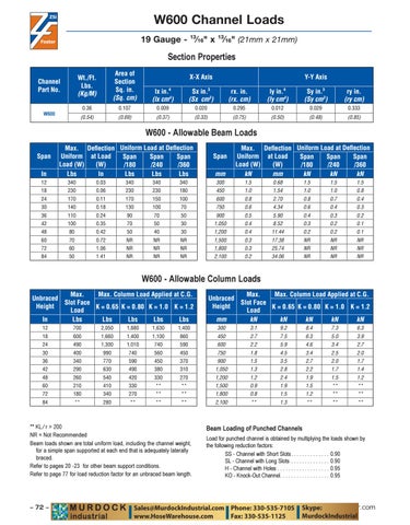
W600 Channel Loads 13
19 Gauge -
Channel Part No.
In
13
⁄16" (21mm x 21mm)
Wt./Ft. Lbs. (Kg/M)
Area of Section Sq. in. (Sq. cm)
lx in.4 (lx cm4)
Sx in.3 (Sx cm3)
rx. in. (rx. cm)
ly in.4 (ly cm4)
Sy in.3 (Sy cm3)
ry in. (ry cm)
0.36
0.107
0.009
0.020
0.295
0.012
0.029
0.333
(0.54)
(0.69)
(0.37)
(0.33)
(0.75)
(0.50)
(0.48)
(0.85)
W600
Span
⁄16" x
X-X Axis
Max. Deflection Uniform Load at Deflection Uniform at Load Span Span Span Load (W) (W) /180 /240 /360 Lbs In Lbs Lbs Lbs
Y-Y Axis
Span mm
Max. Deflection Uniform Load at Deflection Uniform at Load Span Span Span Load (W) (W) /180 /240 /360 kN mm kN kN kN
12
340
0.03
340
340
340
300
1.5
0.68
1.5
1.5
1.5
18
230
0.06
230
230
180
450
1.0
1.54
1.0
1.0
0.8
24
170
0.11
170
150
100
600
0.8
2.70
0.8
0.7
0.4
30
140
0.18
130
100
70
750
0.6
4.34
0.6
0.4
0.3
36
110
0.24
90
70
50
900
0.5
5.90
0.4
0.3
0.2
42
100
0.35
70
50
30
1,050
0.4
8.52
0.3
0.2
0.1
48
80
0.42
50
40
30
1,200
0.4
11.44
0.2
0.2
0.1
60
70
0.72
NR
NR
NR
1,500
0.3
17.38
NR
NR
NR
72
60
1.06
NR
NR
NR
1,800
0.3
25.74
NR
NR
NR
84
50
1.41
NR
NR
NR
2,100
0.2
34.06
NR
NR
NR
Max. Max. Column Load Applied at C.G. Unbraced Slot Face Height K = 0.65 K = 0.80 K = 1.0 K = 1.2 Load In Lbs Lbs Lbs Lbs Lbs
Max. Max. Column Load Applied at C.G. Unbraced Slot Face Height K = 0.65 K = 0.80 K = 1.0 K = 1.2 Load mm kN kN kN kN kN
12
700
2,050
1,880
1,630
1,400
300
3.1
9.2
8.4
7.3
6.3
18
600
1,660
1,400
1,100
860
450
2.7
7.5
6.3
5.0
3.9
24
490
1,300
1,010
740
590
600
2.2
5.9
4.6
3.4
2.7
30
400
990
740
560
450
750
1.8
4.5
3.4
2.5
2.0
36
340
770
590
450
370
900
1.5
3.5
2.7
2.0
1.7
42
290
630
490
380
310
1,050
1.3
2.8
2.2
1.7
1.4
48
260
540
420
330
270
1,200
1.2
2.4
1.9
1.5
1.2
60
210
410
330
**
**
1,500
0.9
1.9
1.5
**
**
72
180
340
270
**
**
1,800
0.8
1.5
1.2
**
**
84
**
280
**
**
**
2,100
**
1.3
**
**
**
⁄ NR = Not Recommended Beam loads shown are total uniform load, including the channel weight, for a simple span supported at each end that is adequately laterally braced. Refer to page 77 for load reduction factor for an unbraced beam length.
– 72 –
Load for punched channel is obtained by multiplying the loads shown by the following reduction factors: SS - Channel with Short Slots . . . . . . . . . . . . . . SL - Channel with Long Slots . . . . . . . . . . . . . . H - Channel with Holes . . . . . . . . . . . . . . . . . . . KO - Knock-Out Channel . . . . . . . . . . . . . . . . . .
www.zsi-foster.com