MADISONWEICK WW
URBAN GREENWAY CONTENTS CONTENTS CONTENTS CONTENTS 01 05 04 08 02 06 03 07 URBAN GREENWAY ELEMENTARY SCHOOL CHAIR JOINERS ABOVE THE 60TH PARALLEL: RECLAIMED OIL RIG PROPOSAL THINKING INSIDE THE BOX COLUMBUS COWORKING TOWER CHICAGO ALLOTMENT CENTER FOUND ARTIFACTS
CHICAGO ALLOTMENT CENTER
[OSU] fourth-year studio semester 2 full semester project instructor: erik herrmann urban farm + community center
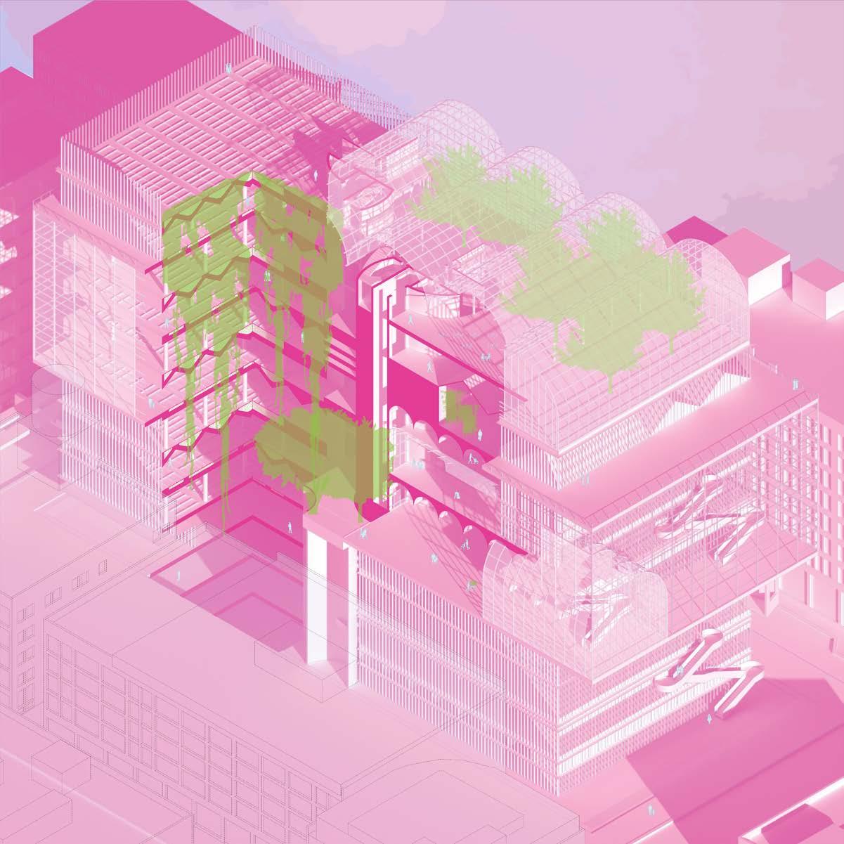
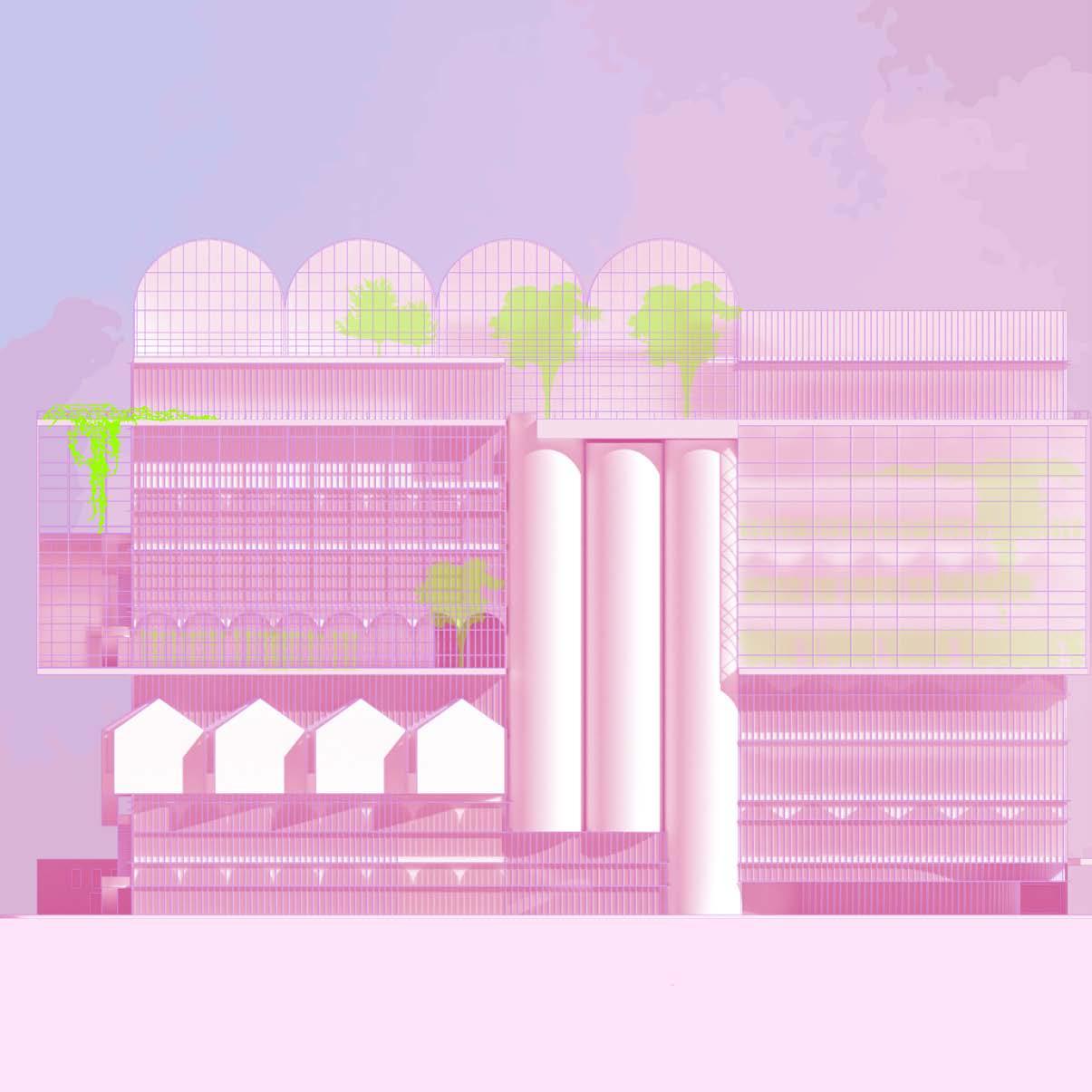
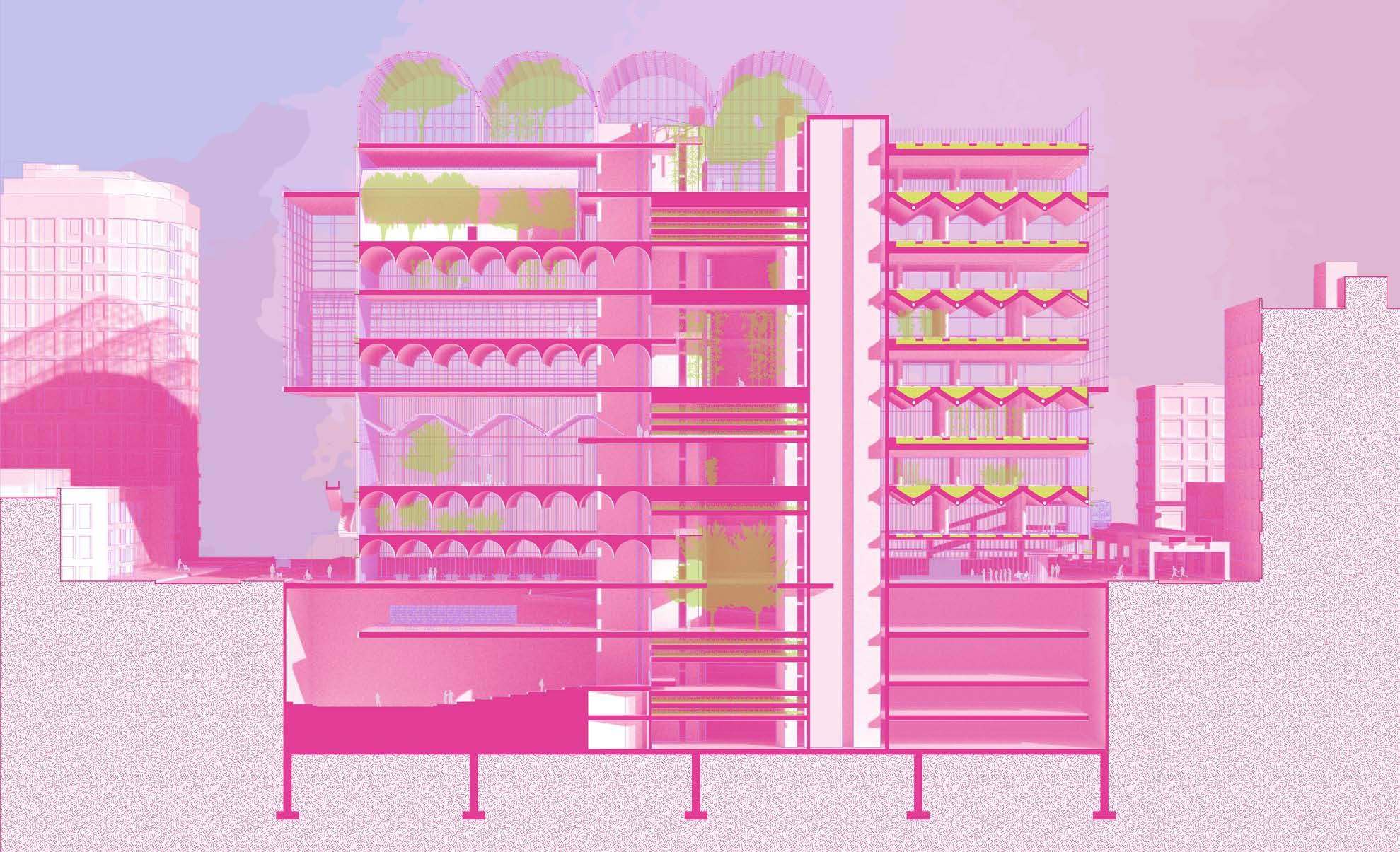
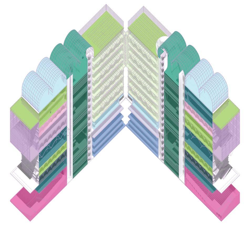
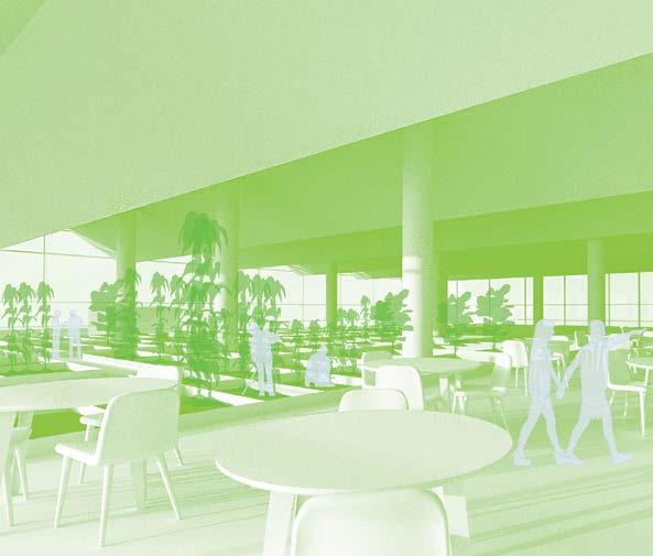
The Chicago Allotment Center is a specialized agricultural guild, which focuses on providing the local Chicago community with designated areas in the city for planting, harvesting, learning, and growth. The main idea behind the center is that the community will see this as their own entity, and care for it so that the building is self-sustaining and not seen as a structure imposed upon by the city or by the architect. Chicago residents have access to individual allotments, as well as communal allotments. These allotments are organized in various districts, neighborhoods, and streets in order to promote a stronger and more diverse community identity. The building is split into unequal thirds, designating space for the individual allotments, communal programming, and hydroponics which separate and bridge the individual and communal areas simultaneously. Greenhouses are incorporated throughout the entire building and connect the three distinct programs. The floorplates mimic the inverse of typical greenhouse roofs, with the gable form being incorporated for the individual allotments and the vault form for communal programming. These shapes allow for an adequate amount of soil depth, water distribution, and grow lights to be organized throughout each harvesting level. The cores reinforce the communal focus of the building by providing an area for shared resources, allowing for more connections between building users to create a larger community.
WW 3
project elevation, which demonstrates the use + play of transparencies in the facade, as well as the visibility + distinction of spaces [left]
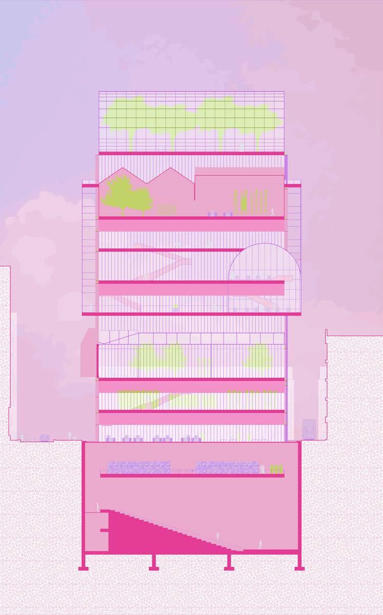
latitudinal sectionhighlights the communal areas of the project [right]
WW 4
longitudinal section perspective: show the lateral tripartite organization of communal spaces, garden spaces, + individual spaces
WW 5
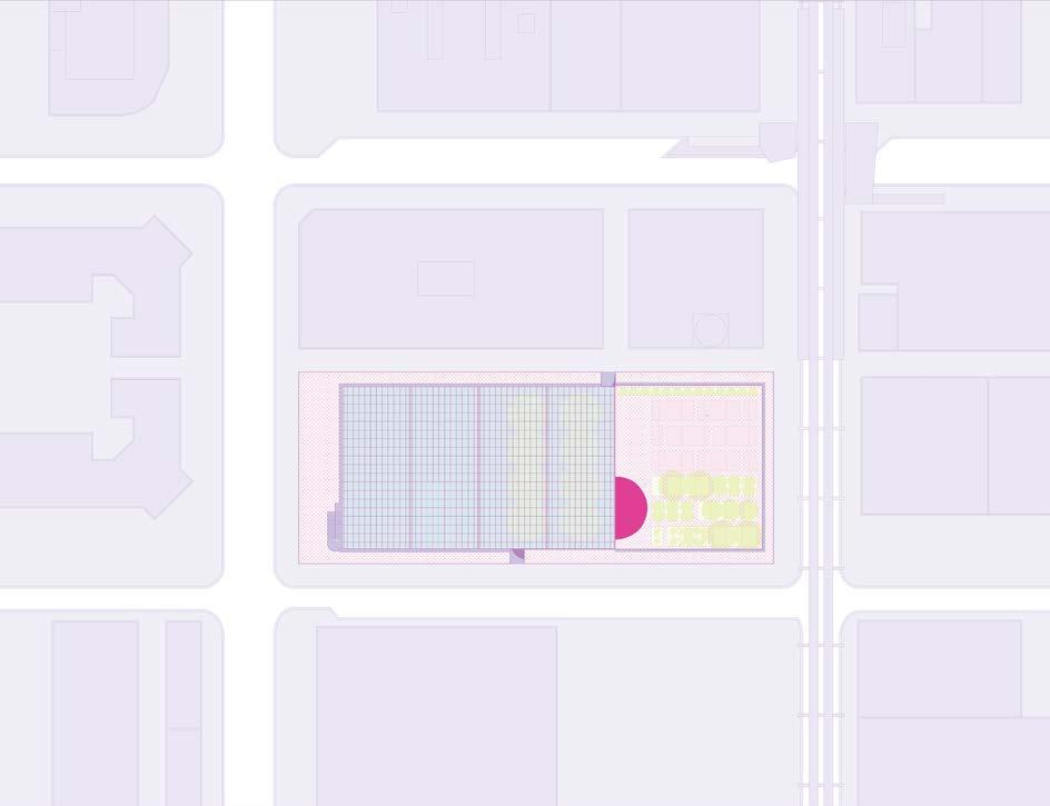
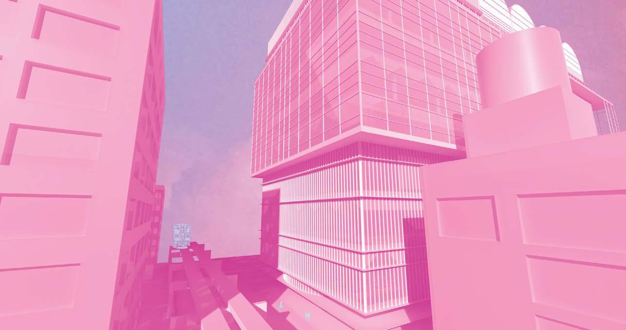
site context & figure/ground plan to demonstrate how the center interacts with public transit, apartments, + other businesses
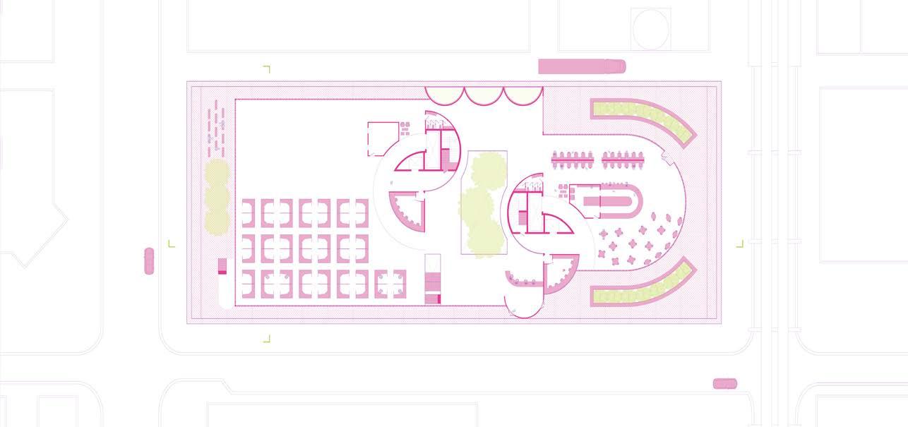
ground level plan, which has four distinct areas: [from left to right] exterior plaza, administrative offices, cores + garden space + main entry, and cafe
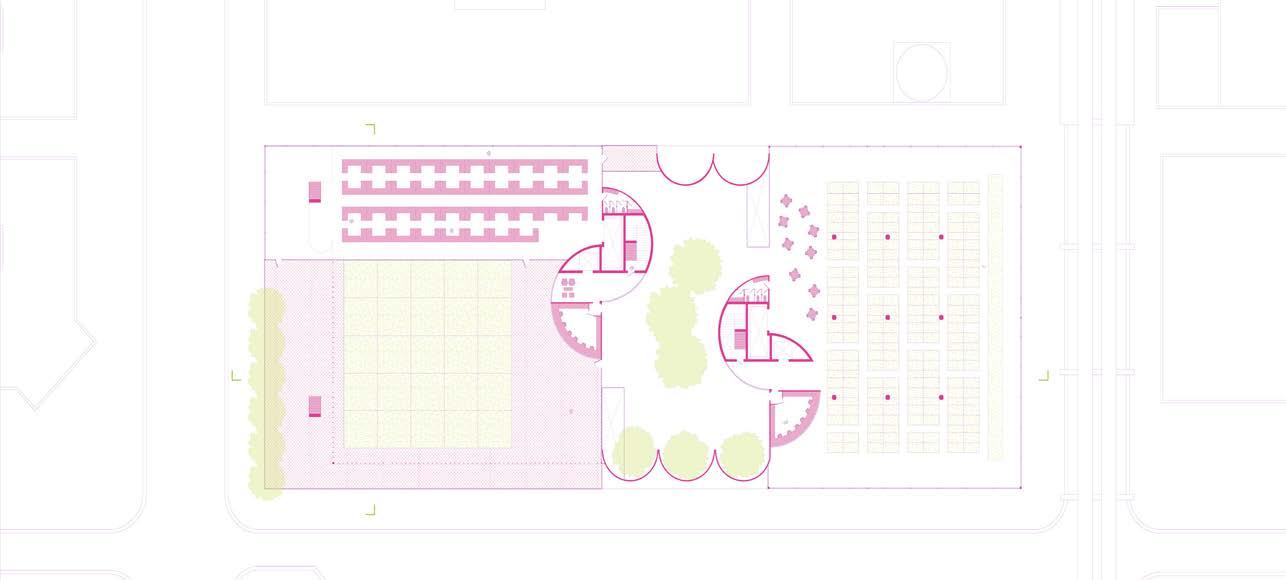
the level 4 plan highlights important community spaces, such as the market, communal allotments, shared agricultural workspace, + garden, as well as a typical individual allotment layout on the right side of the building
WW 6
PROGRAMMING
communal gardens individual allotments greenhouses various hydropoincs learning + research administration
market + direct growth space
public food bank
seed bank
auditorium
dining services
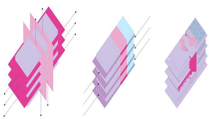
recipe diagram:
WW 7
split squish fill
SYSTEM DIAGRAMS
park district
DISTRICT + CIRCULATION
public circulation // functional private circulation // experiential
TYPICAL FLOORPLATE STRUCTURE
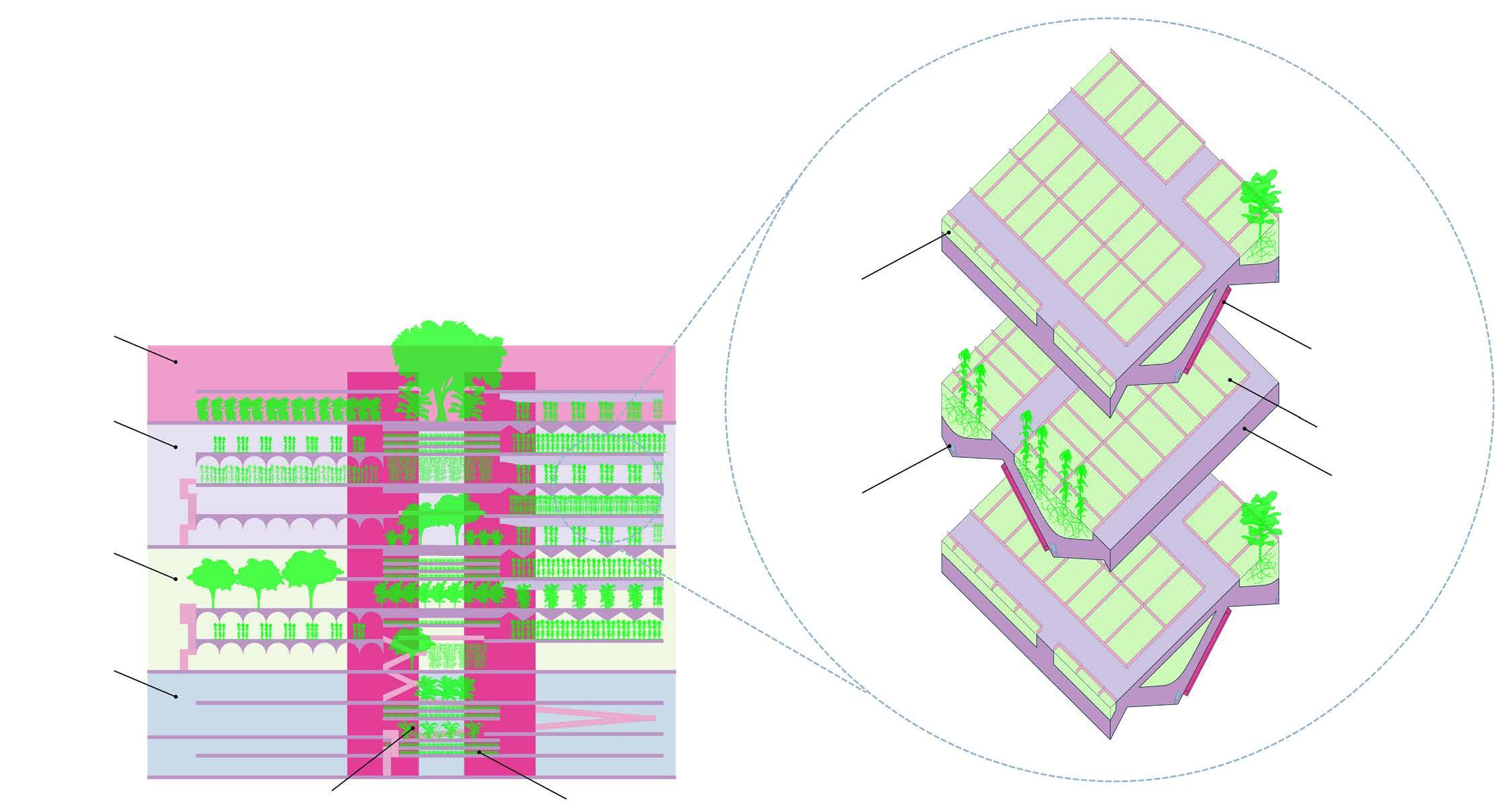
soil
grove district
water distribution system
grow lights individual allotments
concrete // structure
garden district
river district
vertical hydroponics [aeroponics, drip systems]
horizontal hydroponics [ebb + flow, deep water culture, nutrient film technique, wicking system]
WW 8
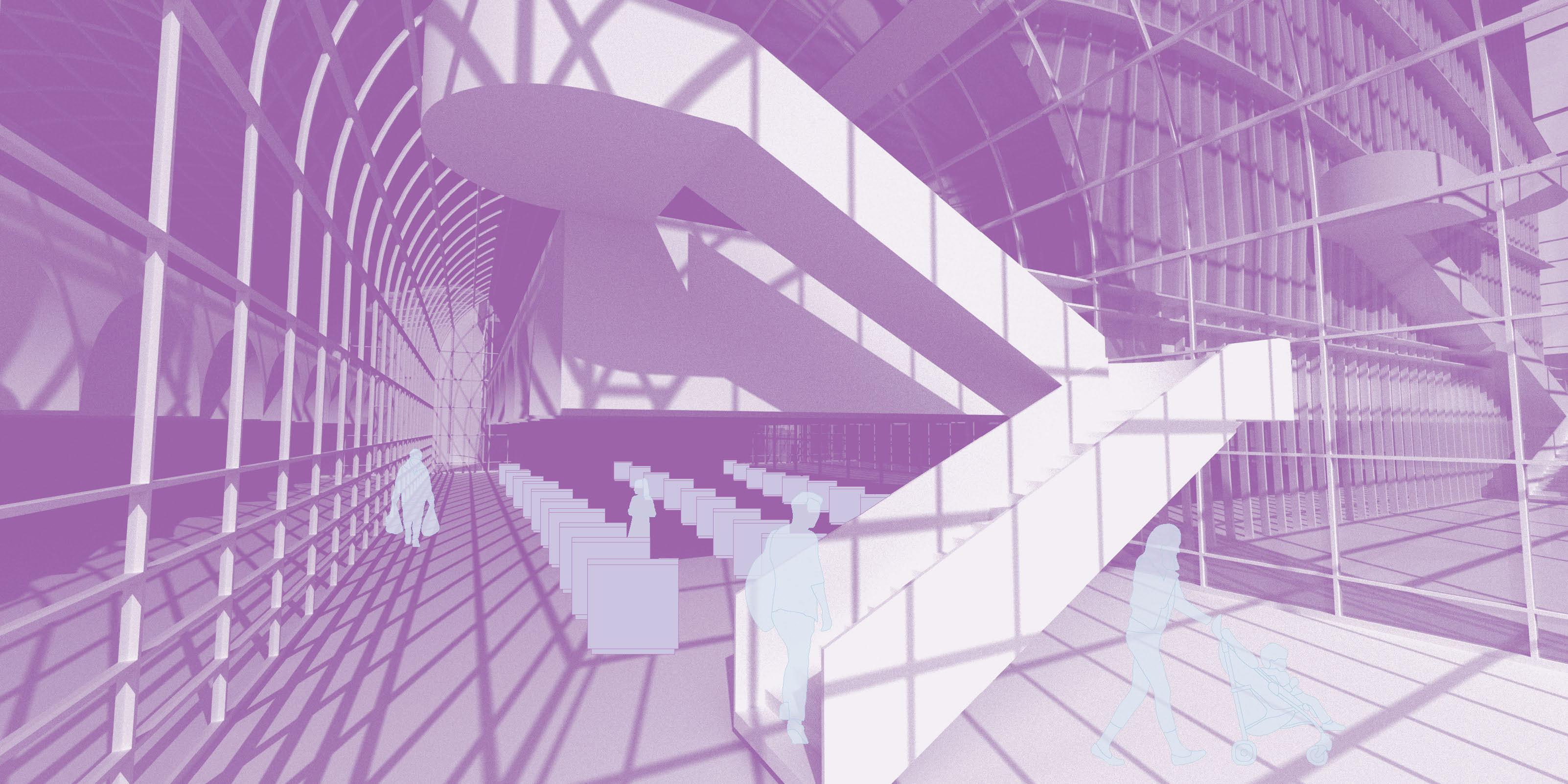
WW 9 interior market rendering
URBAN GREENWAY
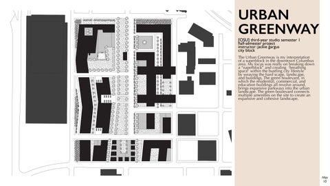
[OSU] third-year studio semester 1 half-semester project instructor: jackie gargus city block
The Urban Greenway is my interpretation of a superblock in the downtown Columbus area. My focus was really on breaking down a “superblock” and creating ‘breathing space’ within the bustling city lifestyle by weaving the hard scape, landscape, and buildings. The green boulevard, in which the residential, commercial, and education buildings all revolve around, brings expansive parkways into the urban landscape. The green boulevard connects multiple amenities on the site to create an expansive and cohesive landscape.
WW 10
site diagrams - site organization, site circulation, & site weaving connections
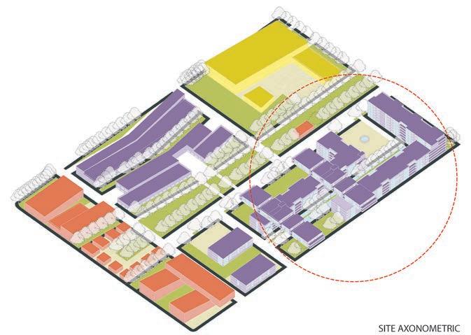
site axon. the high-density housing is being called out. the enlarged axon of the housing can be seen below
HOUSING COMMERCIAL EDUCATIONAL
PARKING ZONES SCHOOL CIRCULATION
DIAGRAM SITE CIRCULATION SCALE: NTS VEHICULAR CIRCULATION
PEDESTRIAN TRAFFIC & PLAZAS BICYCLE CIRCULATION
high-density housing axon
WW 11
SITE PLAN SCALE: 1” = 50’0”
VERTICAL CONNECTIONSHORIZONTAL CONNECTIONS PARK CONNECTIONS WEAVING DIAGRAM SCALE: NTS SHARED WORKSPACES HOUSING UNITS VERTICAL CIRCULATION
high-density apartment plans
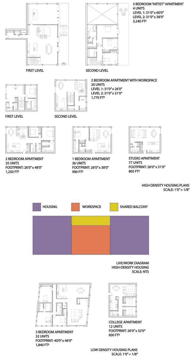
high-density housing & workspace organizational diagram
low-density & college apartment plans
HIGH DENSITY LEVEL 5 PLAN SCALE: 1/16” = 1’0” SECTION A SECTION B WW 12 level 5 floor plan
URBAN GREENWAY ELEMENTARY SCHOOL
[OSU] third-year studio semester 1 half-semester project instructor: jackie gargus educational building
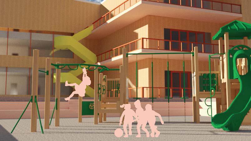
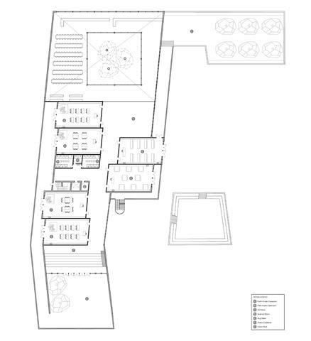
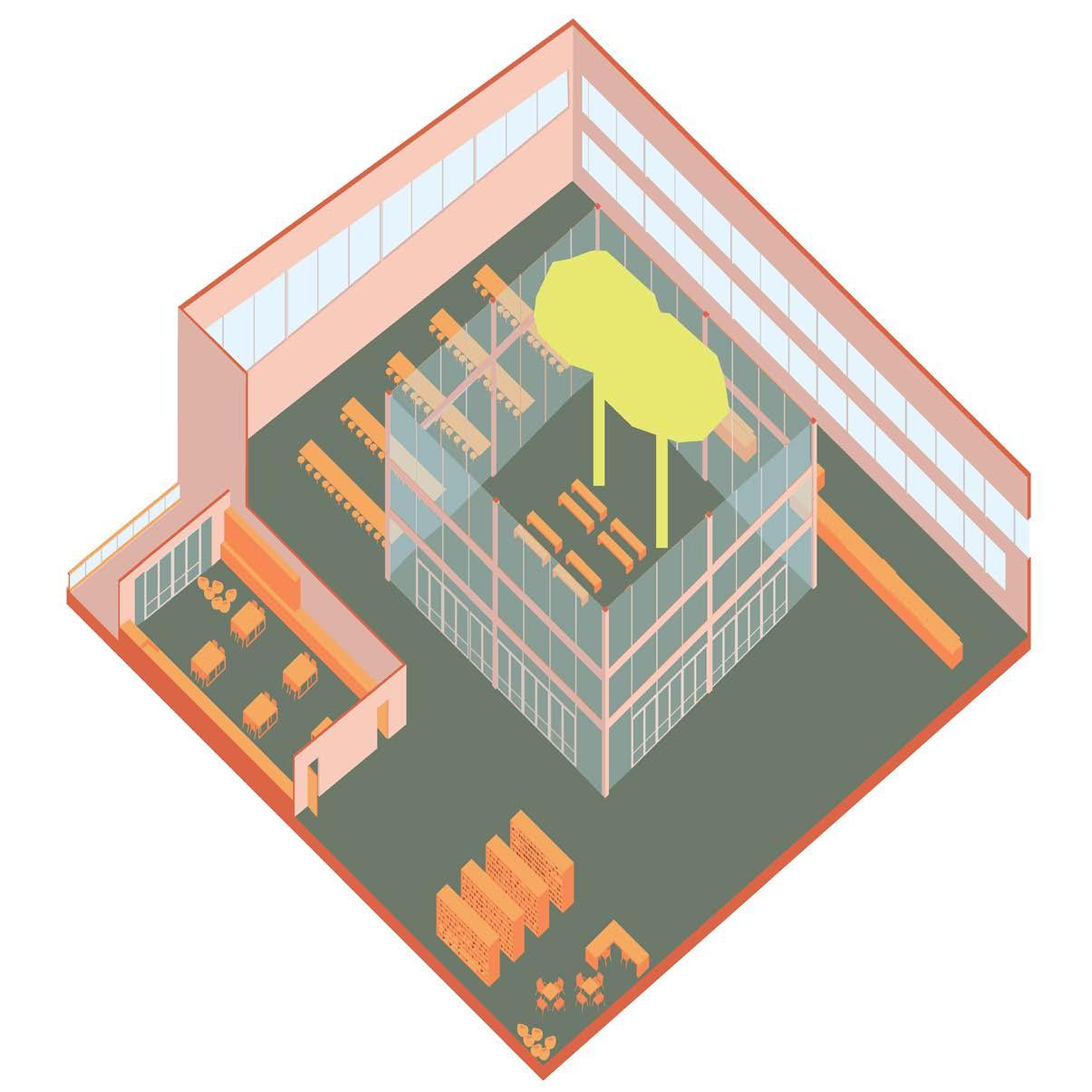
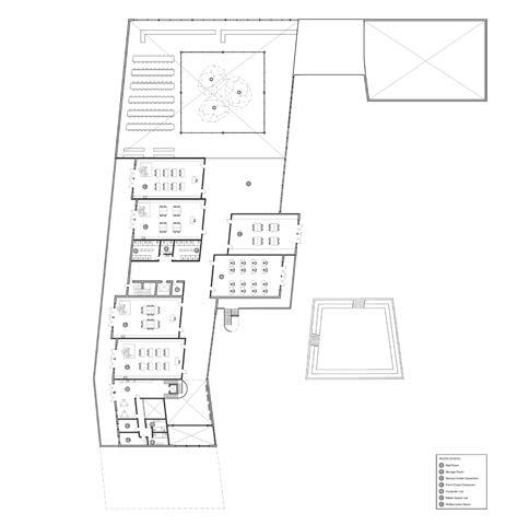
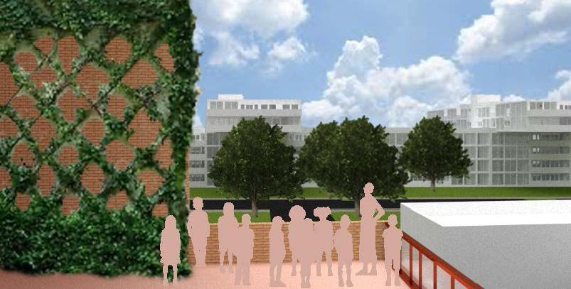
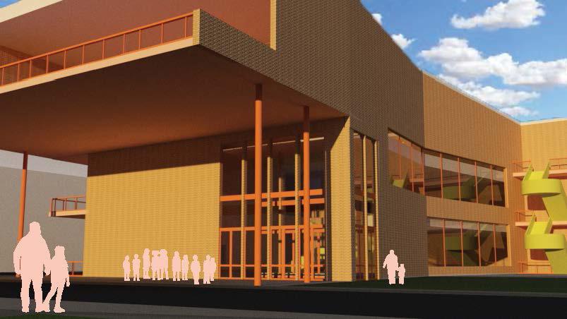
The elementary school on our urban Columbus site is situated in the back left corner of the site, in order for it to be more private and sit the furthest away from the busy road, Mt. Vernon. This allows the bus and parent drop-off lanes to not clog up the main road. It’s massing is derived from the weaving of the entire site, especially regarding the high and low density housing. Green spaces are incorporated throughout the school in order to promote the important connection to nature. Each classroom has access to a joined balcony, in which the concept comes from my precedent research of the Open Air School in Amsterdam.
WW 13
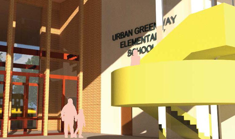
WW 14 entry lobby & staff stairs
detail cut-away axon highlighting the courtyard, cafeteria, library, & classroom
WW 15
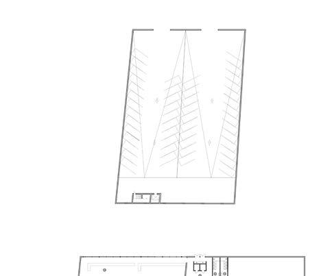
parking level plan
level 1 plan
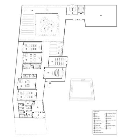
level 2 plan
level 3 plan
WW 16
exterior ‘green cantilever’ over-looking the highdensity housing & the green boulevard on the site
section
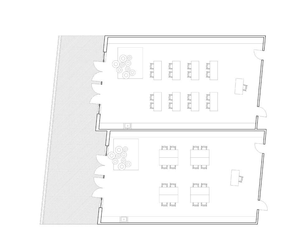
typical classroom plan with exterior classroom balcony connection between the two
long
front entrance of the school, emphasizing the large windows in order to allow as much natural light as possible
WW 17
CHAIR JOINERS
[OSU] second-year graphics & representation quarter-semester project instructor: ashley bigham & erik herrmann collaging & abstraction study
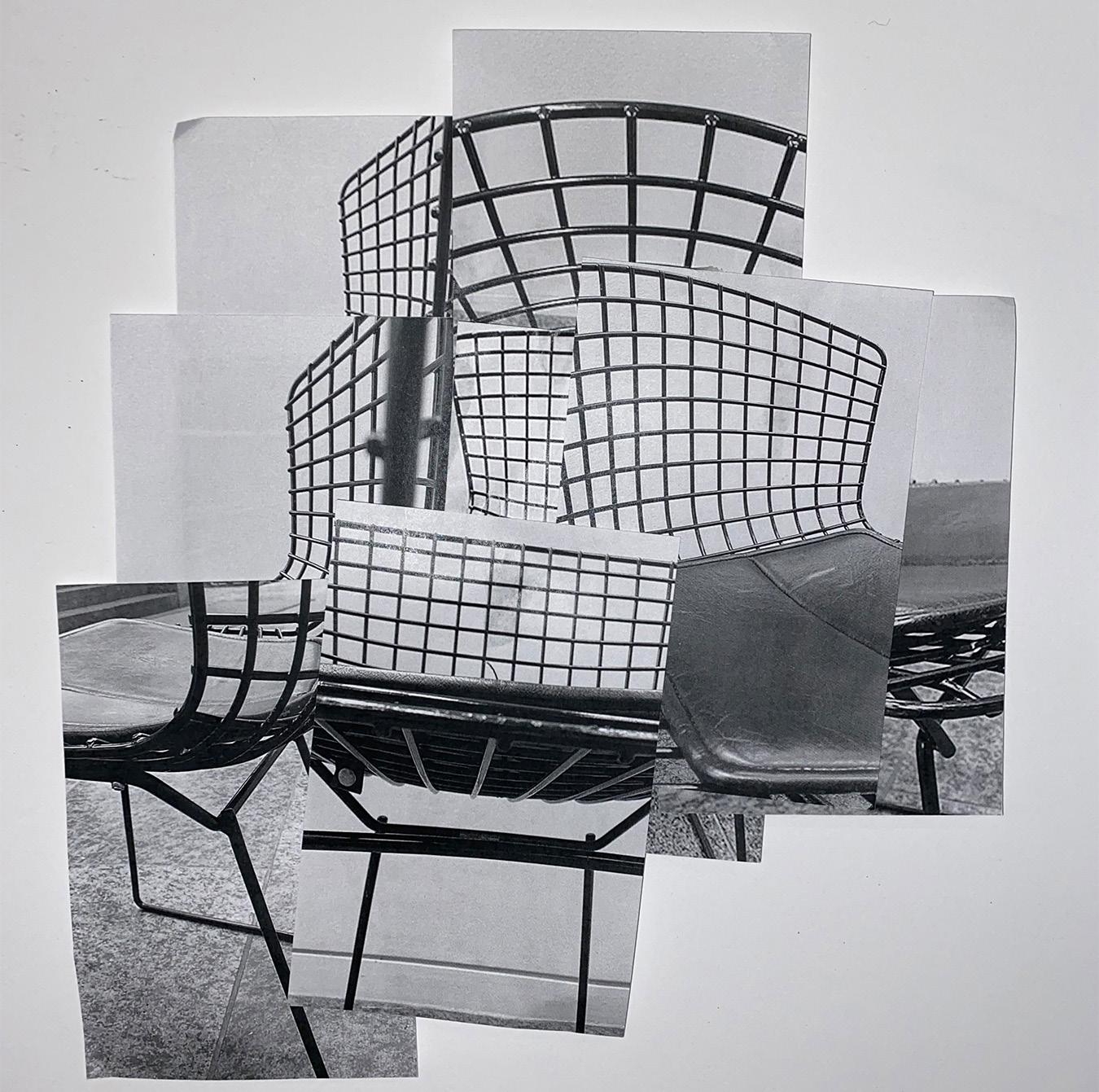
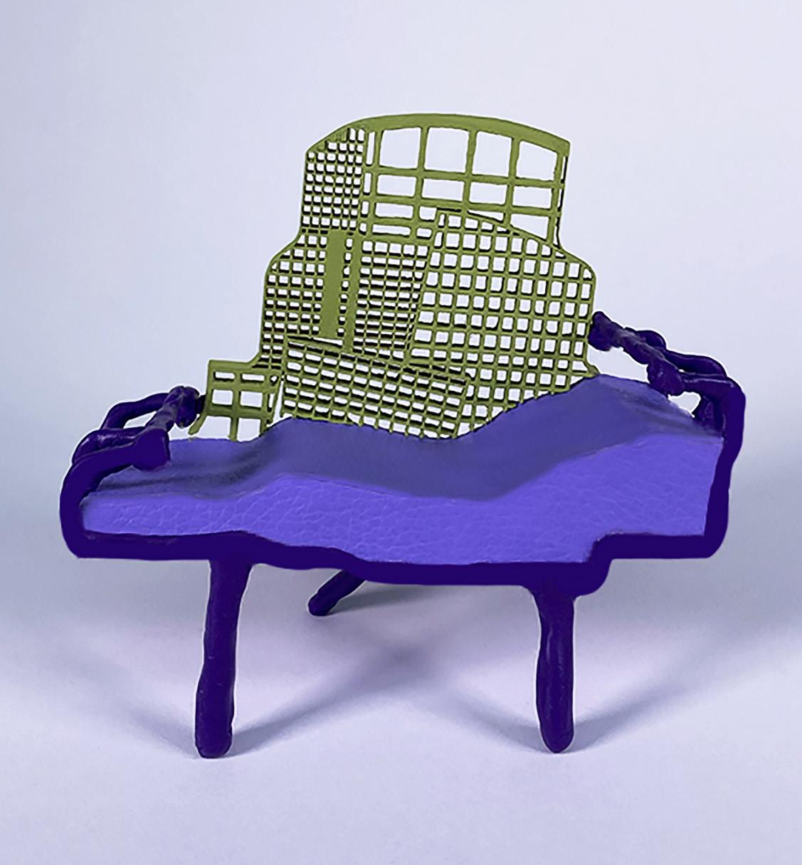
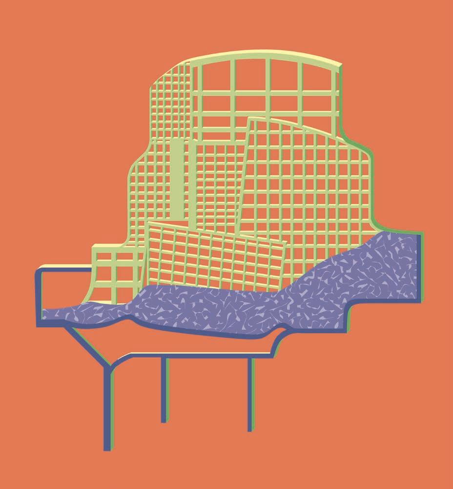
Inspired by artist David Hockey and his interesting compositions, we were tasking with abstracting a chair by taking multiple photos of the chairs from various angles and then creating multiple compositions through these photos. After we chose a final composition, we traced the chair in Rhino to create three drawings of our new chair in an elevation oblique view: pure line work, no line work with only fills and patterns, and a combination of line work and fills. Using one of the color combinations we used in a colored drawing, we were tasked with modeling our new chair in Rhino, as well as physically. They were to be as accurate color- wise and structure-wise, as possible. I chose to abstract a Harry Bertoia Wire Chair found in the Wexner Center for the Arts due to the simple beauty. The differing scales of the grid in picture allowed me to compose a chair with a more intriguing back.
WW 18
physical chair model, highlighting the materiality
WW 19
elevation oblique view; only fills & hatches, no line work
THINKING INSIDE THE BOX
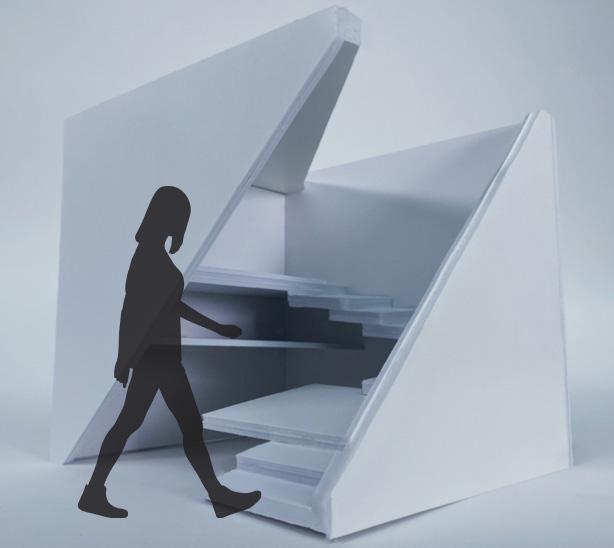
The inspiration behind this project was regarding ‘quarantine’ spaces, or the other phenomenon of ‘pop-up’ offices. These spaces focus on creating intriguing backgrounds for Zoom calls and compact working/learning spaces, that can all be assembled easily within someone’s home. The size restrictions on the offices cubes was 8’- 0” x 8 - 0” x 8’- 0”, with the criteria including a space for a video camera or laptop, interesting background, and no additional furniture needed in the space, other than possibly lighting.
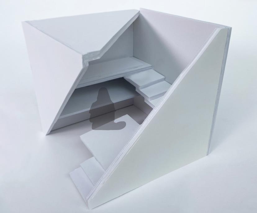
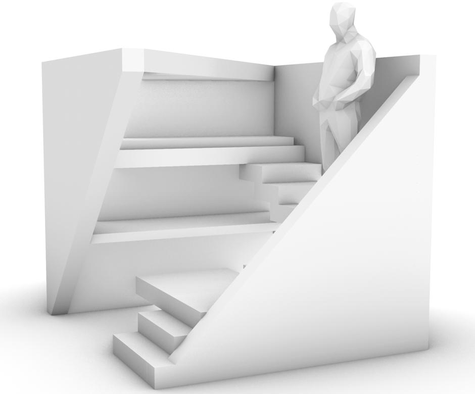
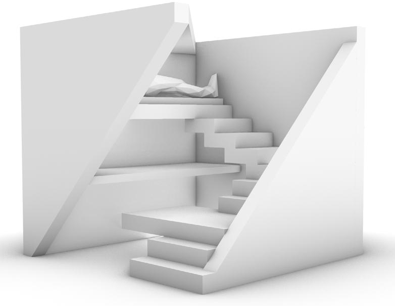
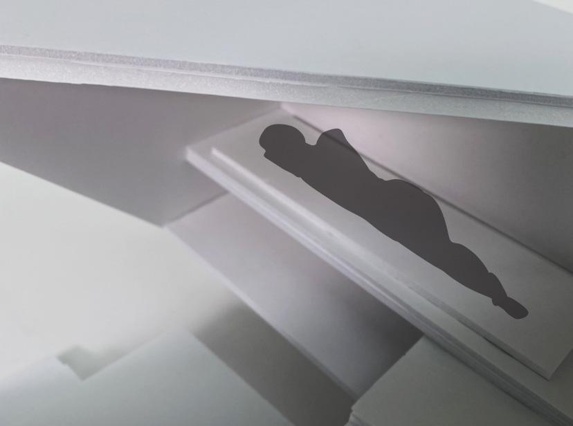
I first decided to create diagonal cuts in the space, which allowed for a partially open room and a partially open ceiling. The diagonal cut on the top of the cube situates itself to allow someone to walk up a series of storage stairs to get up to the rest area, or to simply do some light exercise as a quick break in their day. The desk is built-in and continues along the entire wall, just as the resting area does above it. Many students have breaks throughout their online schooling days, which allow just enough time for a quick nap. This nap can take place in this cube, so they do not have to go far from their studies. The chair for the desk doubles in use as a stair, in order to save space and allow it to be built-in. If the user of the space finds it uncomfortable, pillows can be brought in to sit on, or the rest area can also double as a more comfortable space to sit and do work.
WW 20
[OSU] third-year studio semester 2 warm-up instructor:project ben wilke compact space study
WW 21
section- demonstrates the room within a room, with the desk, seating, storage, & rest area
model photo
rendering which shows the room user on the stairs
elevation- shows the storage stairs with built-in seating, that lead up to the rest area, or can be used for light exercise
WW 22
room in a room features
2 3 3 1
1 - stairs & storage 2 - rest space
3
- work space
model photo highlighting the rest area [top]
rendering showing the entirety of the cube [bottom]
FOUND ARTIFACTS
[IIT] first-year design communications III final projectinstructor: daniel caven modeling + rendering study
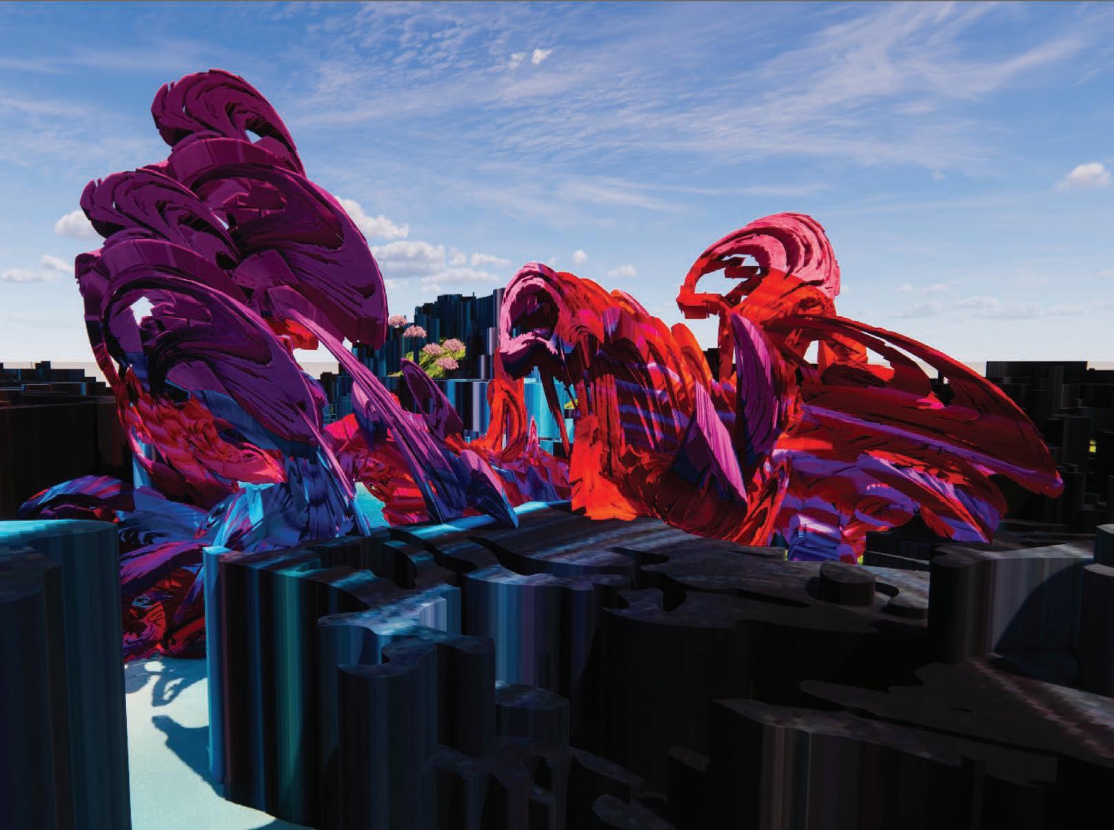
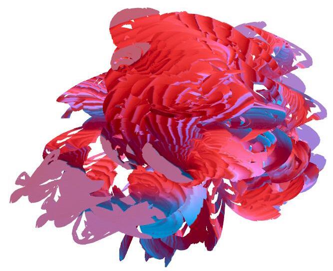
In this highly experimental course, we were tasked with creating objects out of simple command patterns in Rhino and Grasshopper. Initially, we began with generating AI images that would start our CAD processes while also providing the materials we would be rendering with.
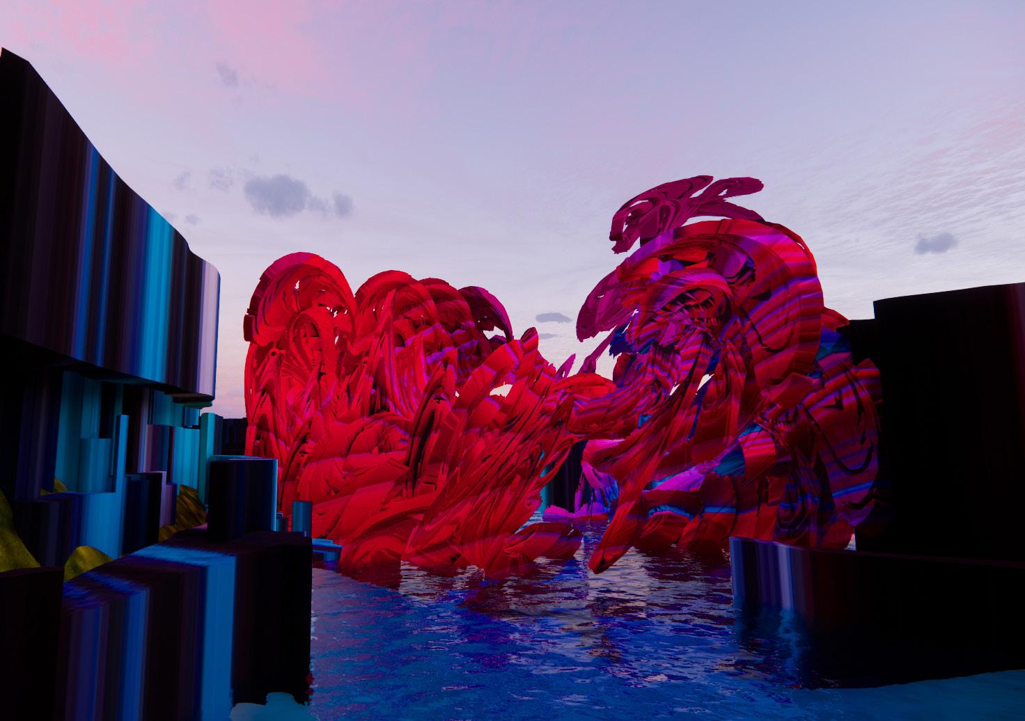
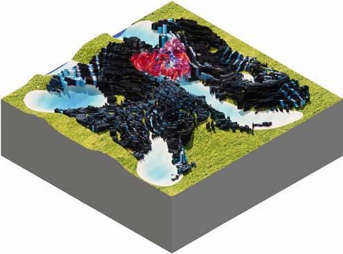
After creating a sort of architectural artifact, we were tasked with placing our object within a landscape. This landscape was to be designed in Rhino based on another AI image that was generated in the first step of the process. The rest of the context is customized using the rendering software, Enscape.
WW 23
PROJECT PROCESS
AI SCRIPTS
“ogranic, water ripple pattern, mountain pattern, something, floating, abstract, earth blob, photorealistic”

“ogranic, patterns, lava, purples and oranges” “ogranic, patterns, small worlds, displacement map” + variation


“ogranic patterns, something, rippling, colorful abstract object”
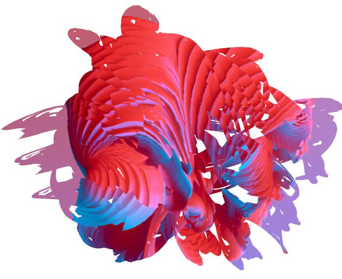

GRASSHOPPER TRANSFORMATIONS + STEPS

WW 24
ARTIFACTS
LANDSCAPE
FINAL OBJECT


WW 25 PROJECT PRODUCT
COLUMBUS CO-WORKING TOWER
[OSU] third-year studio semester 2 full-semester project instructor: ben wilke co-working tower
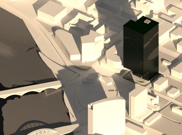
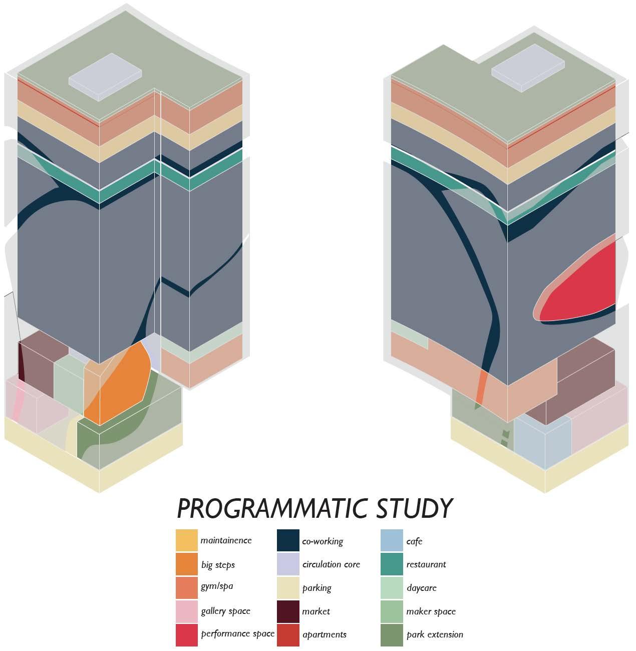
The task at hand was to construct a coworking tower on the Columbus skyline, which eloquently brings together multiple programs into one building: a Bicentennial Park extension, co-working spaces, a performance space [theater], a large gathering space [big steps], gym/spa, market, daycare, restaurant, cafe, gallery, maker space, apartments, and parking. The concept behind my tower was derived from the curvatures of the Sciotio River. The tower has a double-skinned facade to promote air flow, plenty of natural light, and sun-shading strategies when required. The cracking results in the designation of unique programs. The tower and the terraced site face the river and park to invite people to wander onto the site and into the gallery and cafe space. The tower holds multiple types of co-working spaces intended for many different uses, such as rentable individual desk spaces, more traditional office spaces, studio spaces, and communal conference, dining, and lounge spaces in a vertical neighborhood organization.
WW 26
columbus skyline viewed from west of the sciotio river
BUILDING SECTIONS
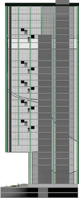
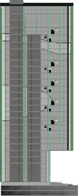
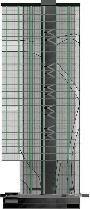
SCALE: 1’0” = 1/32”
MADISON WEICK
site/ground-level
 SECTION C
SECTION D
SECTION C
SECTION D
WW 27
+0.5 +1.5 +2.5 +3.5 +4.5 +5.5 +6.5 +7.5 +8 +6 +5 +4 +3 +2 +7 A B C D E tower sections
SECTION E
plan
programmatic study
WW 28
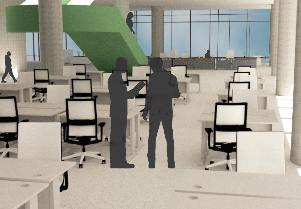
co-working perspective of an office level of the neighborhood
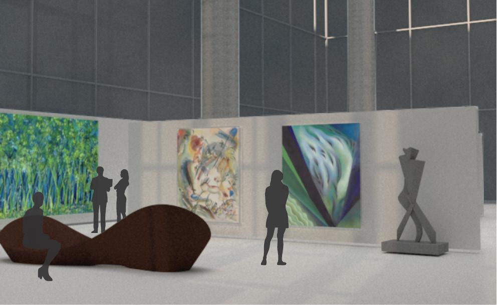
interior view of the gallery space on the ground floor of the tower
vertical neighborhood diagram of co-working spaces, with each ‘neighborhood’ consisting of the three levels to the right, with two work spaces connected by a communalprogrammed floor
work space plan with studio spaces, private offices, rentable desk space, & a traditional office area
shared space plan with conference rooms, dining areas, & lounge spaces
work space plan
WW 29
ABOVE THE 60 PARALLEL: RECLAIMED OIL RIG PROPOSAL
[OSU] fourth-year studio semester 1 full-semester project instructor: ann pendleton-jullian research & design speculation partner: holly smithberger [hs]
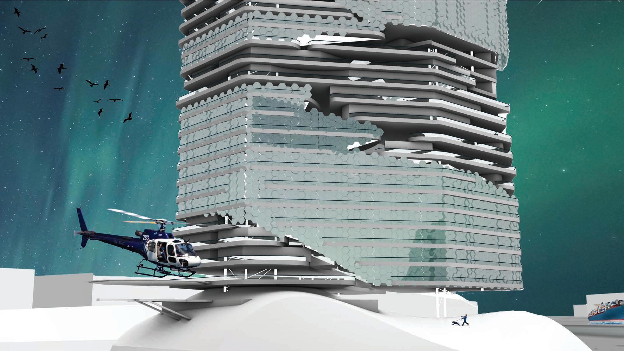
Initially, Arctic countries relied heavily on their oil reserves for economic growth and development. By 2060, the goal was to be carbon neutral in the Arctic Federation, especially from the new archipelagos. The transformed jack-up oil rigs were able to turn into places of population growth, governmental strength, and cultural development, while also maintaining a status of being self-sufficient.
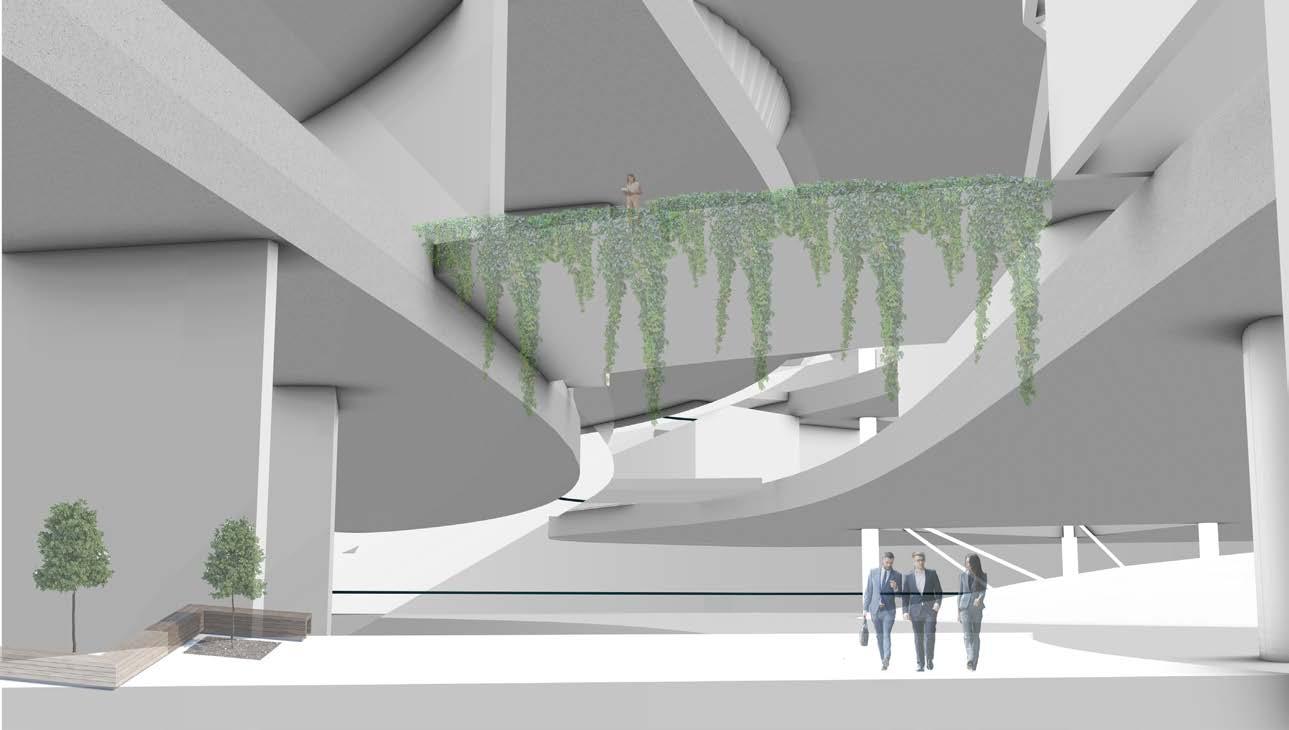
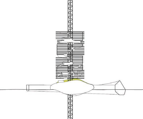
The oil rig is organized by a central ribbon shape, which designates third spaces in the center of the rig, and helps shape both the housing and governmental buildings. The start of this ribbon is where the base level terraforming meets the first level of the public and governmental programming. The third spaces serve as the point of connection between the public and their government, creating a neutral point of conversation, as well as a way for people to have a voice in their government. While still maintaining a distinct separation between civil and public spaces, moments are created which help break these formal barriers and systems.
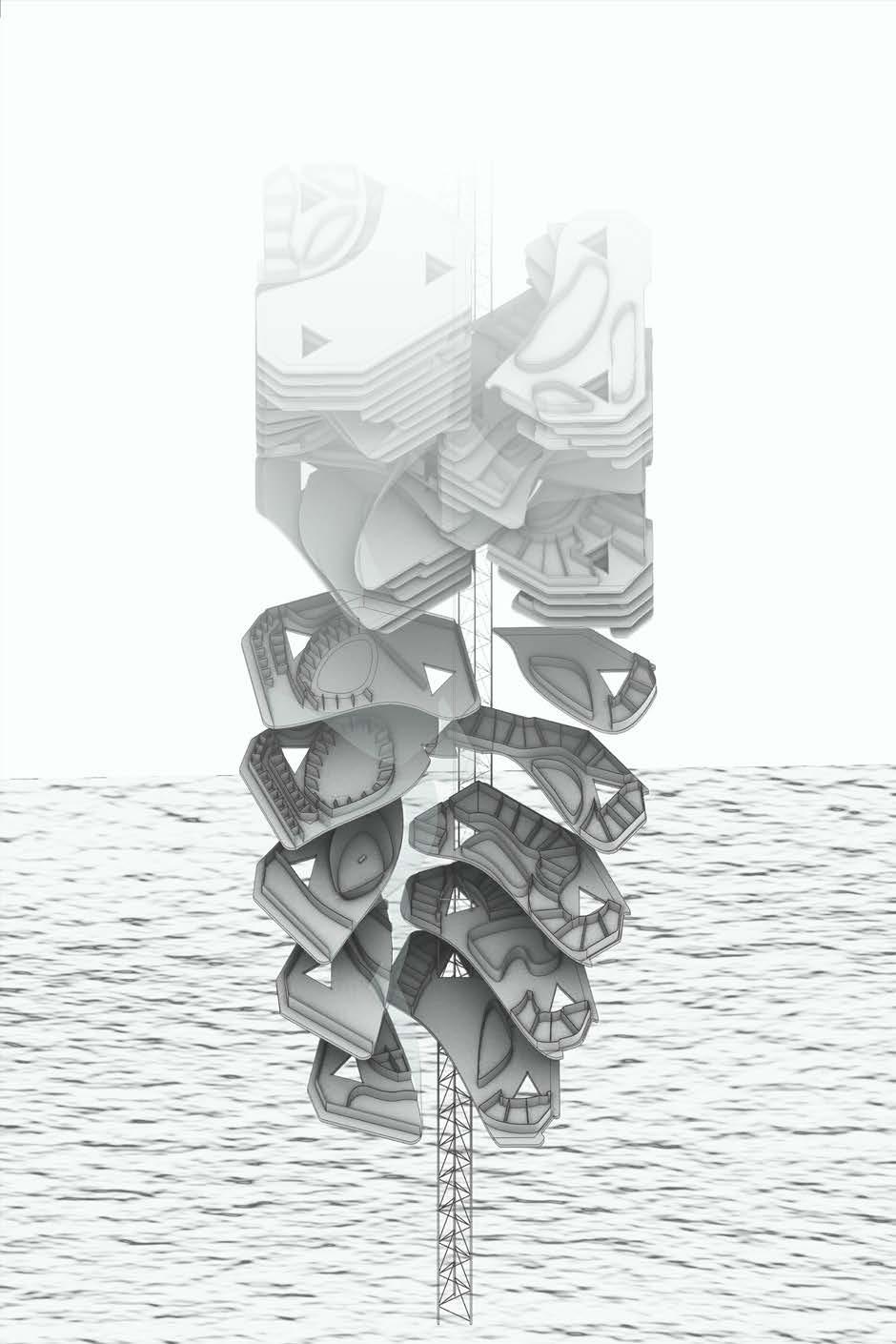
The floor plates never touch, with the cracking representing the constant play and shifting of oil and water, thus representing the government and public sector. These plates are connected by walkways, which become the third spaces where different groups of people can interact.
WW 30
TH
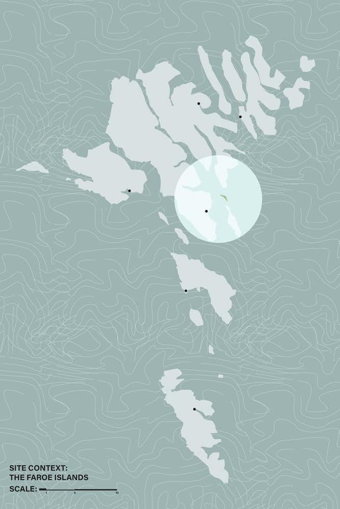
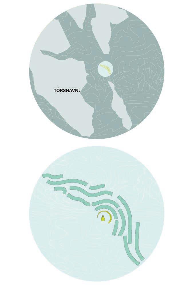
map of the site context, which was decided to be the faroe islands, even though they are not in the arctic circle, they are a beautiful point of current geopolitical neutrality. the vertical striations of the artificial trash islands mimic that of the faroe islands, forming around the hydropower harvester. these islands develop in year 20.
‘cracked open’ diagram- highlights the year zero floor plates [first five], as well as the continuing floor plates, which are added on in fives, incrementally
WW 31
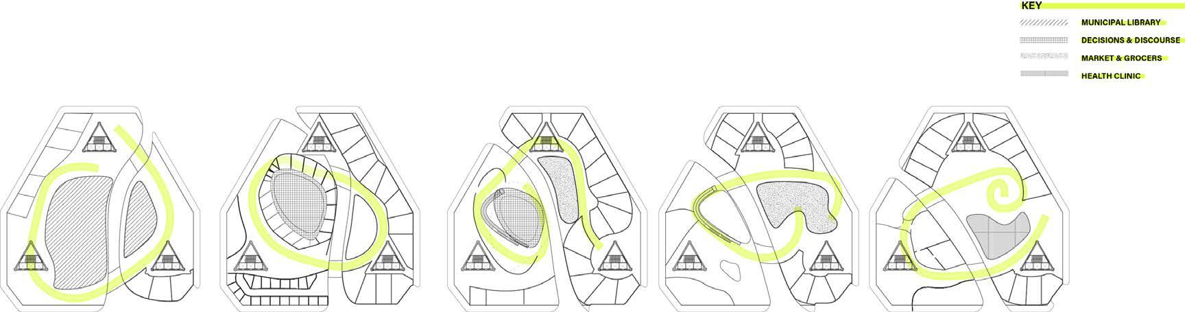
year 0 plans- these floor plates will be available for governmental & public use the first year on the oil rig; the ribbon is green
the cracking of the floor plates, which show the third spaces as the points of connection with greenery
organizational diagram- the ribbon begins to organize each side of the floor plates, creating 3rd spaces
WW 32 level 1 level 2
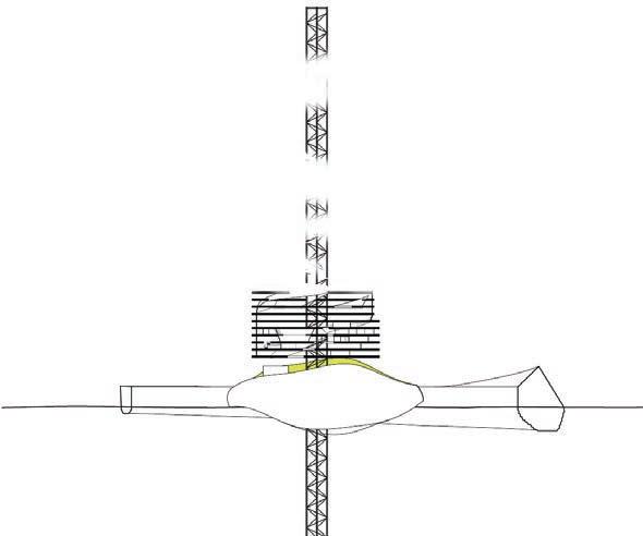
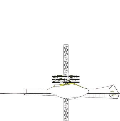
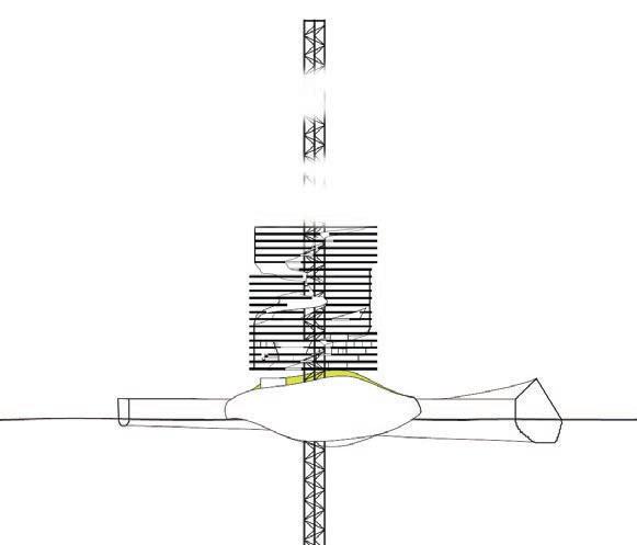
WW 33 year 0 year 5 year 10 year 20
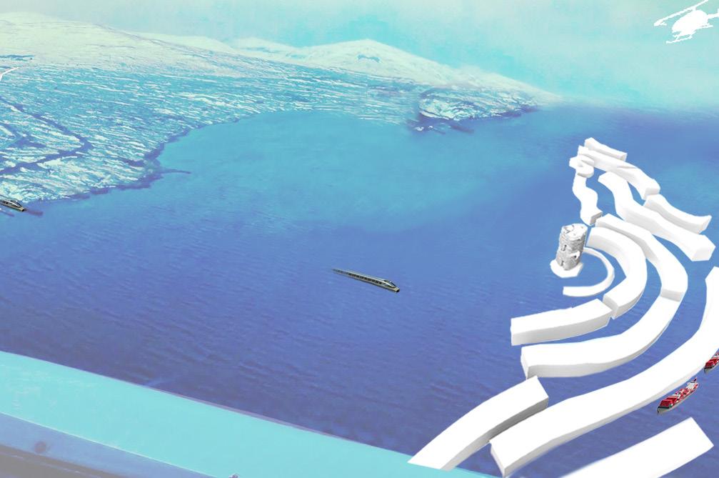
‘out of helicopter view’ rendering [hs]
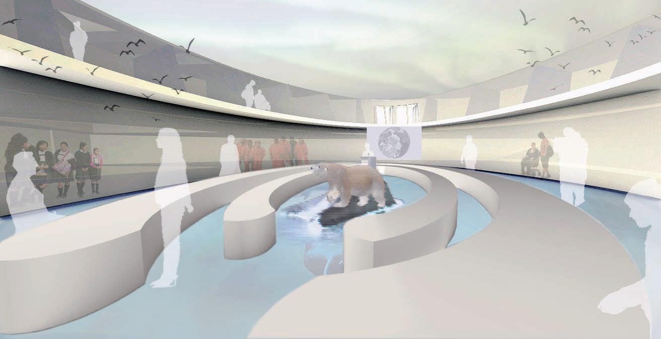
‘parliament chambers’ rendering [hs]
reclaimed oil rig transformation sections [hs]