GAS LINES
COMPANY NEWS
www.compressortech2.com OCTOBER 2026
The challenge of CCUS
SIEMENS FPSO WIN
NEXTERA’S POWER PLANT
A KHL Group publication
RECORD-SETTING PRODUCTION
SHALE PLAY-BY-PLAY
CORNERSTONES OF COMPRESSION
MIKE BROOKS, CEO GLOBAL COMPRESSION SERVICES
WHATEVER HAPPENED TO ESG?
SUBSCRIBE
NOW!
COMPRESSOR & ENGINE PROBLEMS
8
FROM THE EDITOR
JACK BURKE
Editor Jack Burke jack.burke@khl.com Vice President of Content, Power Becky Schultz becky.schultz@khl.com
PRODUCTION Client Success & Delivery Manager Charlotte Kemp charlotte.kemp@khl.com Group Designer Jade Hudson Customer Success & Creative Assistant Cuan Hansbury
CIRCULATION Subscriptions circulation@khl.com Data Manager Anna Philo anna.philo@khl.com Data Executive Vicki Rummery vicki.rummery@khl.com
EVENTS Events Manager Steven Webb steven.webb@khl.com
SALES Brand Manager PLUS USA/Mainland Europe Kristin Pride +1 720 298 8546 | kristin.pride@khl.com China Cathy Yao +86 (0)10 6553 6676 | cathy.yao@khl.com Japan Michihiro Kawahara +81 (0)3 32123671 | kawahara@rayden.jp Scandinavia/UK/Benelux Greg Roberts +44 (0) 7950 032224 | greg.roberts@khl.com Vice President Sales, Power Division Tony Radke 480 478 6302 tony.radke@khl.com Global Vice President Sales Alister Williams +1 312 860 6775 alister.williams@khl.com Chief Executive Officer James King Chief Financial Officer Paul Baker
© Copyright KHL Group, 2026 KHL GROUP AMERICAS LLC 14269 N 87th Street, Suite 205, Scottsdale, AZ 85260. americas@khl.com
www.compressortech2.com
Europe’s LNG equation
E
COMMENT
EDITORIAL
urope has spent much of the past several years trying to answer a fundamental question about its natural gas supply: Where will the next molecule come from? The answer matters considerably to the U.S. midstream industry. New Wood Mackenzie research suggests the European Union could import more than 98% of its natural gas by 2050 if no new domestic fields are developed. Under that scenario, LNG increasingly fills the gap left by declining European production, an expected reduction in Norwegian supply, pressure on North African exports and the phaseout of Russian pipeline gas. And much of that LNG would come from the United States. Wood Mackenzie projects LNG could increase from roughly 40% of EU gas supply today to 63% by 2050. Of that LNG, 77% is expected to come from the United States. Those percentages represent an enormous potential pull on the U.S. natural gas system. More sustained European demand means more gas moving out of producing basins, through gathering and processing systems and into long-haul pipelines serving export facilities. That requires compression — and potentially a great deal of it. But Wood Mackenzie’s analysis also illustrates why the U.S. midstream sector shouldn’t simply assume Europe’s growing LNG dependence is inevitable. The consultancy modeled three European production scenarios. Without new field investment, EU production falls from 43 billion cubic meters in 2028 to just 2 bcm in 2050. Under its high case, however, production reaches 77 bcm by 2042 and supplies 38% of EU demand. The cumulative difference between the scenarios approaches 1,000 bcm. Exploration accounts for much of the potential upside, particularly in the Black Sea and East Mediterranean. Fiscal policy, permitting and exploration success over the next several years could therefore determine how much European gas ultimately competes with U.S. LNG. There are economic reasons for Europe to pursue it. Wood Mackenzie estimates U.S. LNG delivered into northwest Europe breaks even at a cost 68% higher than gas from Romania’s Neptun Deep development and 96% higher than new Norwegian gas. That makes Europe’s domestic production debate more than an energy-security issue. Yet even Wood Mackenzie’s high-production case doesn’t make Europe self-sufficient. Domestic production would meet 38% of demand at its peak under that scenario. Europe would still need substantial imports, and LNG would remain part of the supply mix. For U.S. midstream companies, that may be the more important takeaway. For an increasingly LNG-connected U.S. midstream sector, Europe’s domestic gas policy has become our business, too.
Jack Burke Editor | jack.burke@khl.com
This is not a concept. We’re running on hydrogen.
THE ARIEL KBH. 25 to 500 Bar at 250kg/hr Ariel’s KBH is a vertically oriented, non lubricated, reciprocating compressor designed to maintain high gas purity, featuring the latest advanced materials allowing for optimal compression efficiency and reliability. Ariel KBH compressors can compress hydrogen gas to pressures up to 7,250 psig (500 barg) for trailer filling, hydrogen mobility, and other hydrogen storage and transport needs.
Find out more at arielcorp.com/hydrogen
INSIDE
OCTOBER 2026
COMPRESSORTECH2 ISSN 1085-2468, is published monthly with combined issues of January/February and August/September by KHL Group Americas LLC, 14269 N 87th, Suite 205, Scottsdale, Arizona, 85260, USA. Periodicals postage is paid at Phoenix, AZ, and additional mailing offices (if applicable). POSTMASTER Send address changes to KHL Group Americas LLC, 11811 N. Tatum Blvd, Suite P118, Phoenix, AZ 85028, USA. Copyright © 2026 KHL Group Americas LLC. All Rights Reserved. Materials protected by U.S. and international copyright laws and treaties. Unauthorized duplication and publication is expressly prohibited.
SUBSCRIBE NOW: Scan this code to receive all the latest news in the gas industry.
MEMBER OF:
www.compressortech2.com
20 Mike Brooks, CEO of Global Compression Services
10
TECHNOLOGY 24 Methane detection closer to operations 29 Critical considerations in choosing CCUS compressors 36 Hydrogen changes the rules of compression
TRENDS 40 Is ESG a dirty word in Midstream? 46 Converting compressor station exhaust into grid power 49 Burckhardt’s new path with Fornovo
20
Mike Brooks, GSC
DEPARTMENTS
3 Editor’s Comment: Europe’s LNG equation 6 Industry News: EFRC announces focus of conference 8 Gas Lines: U.S. natural gas production on track for record year 10 Company News: Capstone’s latest win 12 Monitoring Government: Age of data at issue 14 Shale Play by Play: NextEra picks plant site 16 Euro Gas Report: Drone explodes near pipeline 53 Events 55 Tech Corner: Web-based fleet management 65 Cornerstones of Compression: Worthington compressors
GAS LINES
COMPANY NEWS
www.compressortech2.com OCTOBER 2026
The challenge of CCUS
CORNERSTONES
MIKE BROOKS,
RECORD-SETTING PRODUCTION
SHALE PLAY-BY-PLAY
SIEMENS FPSO WIN
NEXTERA’S POWER PLANT
OUTSIDE
Scan the QR code to find us on LinkedIn: COMPRESSORTECH2
INTERVIEW
NOW!
OF COMPRESSION
CEO GLOBAL COMPRESSION SERVICES
WHATEVER HAPPENED
SUBSCRIBE
VOLUME 31 | NUMBER 8
49
A KHL Group publication
36
CONTENTS
40
TO ESG?
29
What to consider in CCUS compression
OCTOBER 2026 | COMPRESSORTECH2 | 5
INDUSTRY NEWS
Burckhardt announces restructuring
B
urckhardt Compression plans to restructure its operations and potentially eliminate up to 220 positions as the reciprocating compressor manufacturer prepares for a lower workload in the coming quarters. The Winterthur, Switzerland-based company said the program will simplify
its organizational structure, consolidate selected functions and optimize business processes. The measures also include a further strengthening of Burckhardt Compression’s organization in India. Up to approximately 150 positions
Managing reciprocating compressor fleets amid changing operating and economic conditions will be the special topic of the 15th EFRC Conference, scheduled for September 2027 in The Hague, the Netherlands. The European Forum for Reciprocating Compressors (EFRC) said the theme, “Managing your fleet of recips in a dynamic environment,” will examine how operators are responding to shifting demands across fleets of machines operating at multiple sites and under different conditions. In Europe, refinery closures have increased pressure on remaining facilities to maximize the performance and availability of existing compressors. At the same time, operators are contending with higher energy costs, volatile crude oil prices and feedstock sources, changing process requirements and spare parts availability. Similar pressures affect process gas plants, where energy costs and cyclical demand can influence compressor operating strategies. EFRC said the conference will focus on how operators balance reliability, maintenance and operating requirements across multiple machines. The 15th EFRC Conference will be held Sept. 28-30, 2027, at the Louwman Museum in The Hague.
at the company’s Winterthur site and another 70 positions at international locations could be affected. Once fully implemented, Burckhardt Compression expects the restructuring to generate annual cost savings of approximately CHF 20 million based on current business volumes. The company anticipates one-time restructuring expenses of about CHF 3 million during the first half of fiscal 2026. The final scope of the restructuring, including the number of jobs affected, will be determined following a consultation process with the company’s Employee Representation Committee in Switzerland. CEO Fabrice Billard said the measures are intended to improve the company’s cost competitiveness and position it for mediumand long-term growth opportunities, particularly those associated with increasing demand for energy security. Despite the expected near-term reduction in workload, Burckhardt Compression said it continues to see growth opportunities in its target markets. The company’s reciprocating compressor systems and services are used in hydrogen, gas infrastructure, chemical processing and industrial gas applications. CT2
ENBRIDGE has secured an exclusive option to acquire the TTC Connector Pipeline, a 25-mile natural gas pipeline under construction that would strengthen the company’s position in the rapidly expanding U.S. Gulf Coast LNG market. The 300 MMcf/d TTC Connector will link Enbridge’s Tres Palacios Gas Storage facility in Matagorda County, Texas, to the Coastal Bend Header pipeline, providing a direct route for natural gas deliveries to the 17 million metric tons per annum (mtpa) Freeport LNG export terminal on Quintana Island. The
International (TSI) division. Financial terms of the transaction were not disclosed. The acquisition adds operations in Alberta and Washington state, strengthening Cooper’s presence across the western United States and Canada while extending its turbocharger service capabilities into marine and small-frame natural gas applications. Founded in 1978, Alamo provides turbocharger overhaul, repair, parts supply and exchange services for customers in the oil and gas, marine, on-highway diesel,
EFRC conference to focus on managing reciprocating compressor fleets
COMPRESSED NEWS
Fabrice Billard, chief operating officer of Burckhardt Compression.
6 | COMPRESSORTECH2 | OCTOBER 2026
pipeline is expected to enter service by the end of 2026. Those projects are expected to increase storage capacity across Enbridge’s four Gulf Coast facilities to approximately 150 Bcf by 2033. COOPER MACHINERY SERVICES has acquired Canadian turbocharger service provider ALAMO INDUSTRIES LTD. (AIL) and ALAMO TURBOCHARGER SERVICES (ATSI), expanding the geographic reach and technical capabilities of its Turbocharger Solutions
www.compressortech2.com
INDUSTRY NEWS
XRG enters Venezuela with stake in Loran offshore project XRG is expanding its international natural gas portfolio into Venezuela after securing an interest in the offshore Loran gas license, which contains more than 4 Tcf of proven gas resources. The international energy investment company established by ADNOC said it was awarded the Loran license by the Venezuelan government, with PDVSA Gas transferring an interest in the license to XRG. Subject to regulatory approvals, XRG will participate in the project alongside bp and UCC. The companies will hold equal interests in the offshore license, according to XRG. Loran is part of the larger LoranManatee gas accumulation, which straddles the maritime boundary between Venezuela and Trinidad and Tobago. The investment gives XRG access to a substantial offshore gas resource with a potential route to market through existing infrastructure. “Venezuela holds significant gas resources and has the potential to play a greater role in meeting regional and international energy demand,” said Mohamed Al Aryani, president, international gas at XRG. XRG described the Loran Phase 2 investment as part of its effort to establish a broader gas and LNG platform in Latin America. The company is assembling an international portfolio intended to connect gas resources with infrastructure and global markets. The Venezuelan investment complements XRG’s existing and planned positions across the Atlantic Basin and other major gas-producing regions. Its portfolio includes an interest in Rio Grande LNG in the United States and Argentina LNG, the latter subject to regulatory approvals.
www.compressortech2.com
Abadi LNG project in Indonesia completes FEED contract awards
I
NPEX has awarded the front-end engineering and design contract package for the onshore LNG plant planned as part of the Abadi LNG project in Indonesia’s Masela Block, completing FEED awards for the project’s four major development packages. The latest award covers FEED for the onshore LNG plant and follows earlier packages covering the floating production, storage and offloading vessel, subsea umbilicals, risers and flowlines, and the gas export pipeline. INPEX Masela Ltd., a subsidiary of Japan-based INPEX, operates the project. The onshore LNG package will use a dual-FEED approach in which two contractor groups will carry out engineering work separately and in parallel. One consortium
consists of PT JGC Indonesia as lead contractor and PT Technip Engineering Indonesia. The second includes lead contractor PT KBR Indonesia, Samsung E&A and PT Adhi Karya. Under the contracting strategy, the consortium submitting the technically and commercially superior FEED proposal is expected to receive the subsequent engineering, procurement and construction work. The FEED scope also includes carbon capture and storage. The Abadi development is designed to produce approximately 9.5 million tons of LNG annually, along with pipeline gas for the Indonesian domestic market. Total natural gas production is expected to be equivalent to approximately 10.5 million tons per year of LNG. CT2
agricultural, mining and power generation sectors. EXXONMOBIL will take over operatorship of the proposed $14 billion Papua LNG project as the development moves closer to a final investment decision (FID), TotalEnergies said. Papua LNG is designed to produce 5.6 million tonnes per annum (mtpa) of LNG from the Elk and Antelope gas fields in Papua New Guinea’s Gulf Province. Papua LNG is expected to primarily supply Asian markets.
OCTOBER 2026 | COMPRESSORTECH2 | 7
GAS LINES
NATURAL GAS PRODUCTION
U.S. natural gas production’s record pace
U
U.S. MARKETED NATURAL GAS PRODUCTION (JAN 2022-DEC 2026)
.S. natural gas production is on track to reach a record in 2026, driven largely by continued growth in the Permian and Haynesville regions, according to the U.S. Energy Information Administration (EIA). In its August 2026 Short-Term Energy Outlook, the EIA forecast U.S. marketed natural gas production will average 122.5 Bcf/d this year, surpassing the previous record of 118.5 Bcf/d set in 2025. Marketed natural gas production averaged 121.3 Bcf/d during the first half of 2026, up 4%, or 4.6 Bcf/d, from the same period a year earlier. The agency said most of that increase has come from the Permian region in Texas and New Mexico and the Haynesville region in Louisiana and Texas. The U.S. was the world’s largest natural gas producer from 2009 through 2024, the latest year for which the EIA has global production data. Permian production remains a major contributor to the growth. The EIA expects natural gas production in the region to
the EIA. That level exceeds estimated breakeven prices billion cubic feet per day reported by oil and gas executives responding to the Dallas Fed Energy Survey. Respondents placed 2026 breakeven prices at $69/b in the Midland Basin and $63/b in the Delaware Basin. The EIA said those relatively high crude oil prices Data Source: U.S. Energy Information Administration, Short-Term Outlook, August 2026 are supporting continued oilNote: 1H2026 = first half of 2026 directed drilling in the Permian and contributing to higher average 29.2 Bcf/d in 2026, up 6% from production of both crude oil and associated 2025. natural gas. Unlike gas-focused plays, Permian Changing reservoir conditions are also natural gas production is driven primarily by increasing gas production. associated gas produced alongside crude The EIA forecasts the Henry Hub spot oil. As a result, oil prices and oil-directed price will average $3.44/MMBtu in 2026, drilling activity remain important factors in down 2%, or 8 cents, from the previous year. determining gas output. At that level, the agency expects drilling in West Texas Intermediate crude oil prices the Haynesville to remain economic despite averaged $84/b through July 2026, up from the formation’s deeper wells and higher an average of $65/b in 2025, according to development costs. T2
BAKER HUGHES RIG COUNT
US NATURAL GAS STORAGE (Bcf) Source: Baker Hughes
1400 1200 1000 800 600 400 200 0 Aug-24
Aug-25 North America
Source: EIA
5000 4500 4000 3500 3000 2500 2000 1500 1000 500 0 January
Aug-26
HENRY HUB NATURAL GAS SPOT PRICE (US$/MMBtu) $8.00 $7.00 $6.00 $5.00 $4.00 $3.00 $2.00 $1.00 Aug-24
8 | COMPRESSORTECH2 | OCTOBER 2026
Aug-25
Five-Year High
Five-Year Low
BRENT CRUDE OIL PRICE (US$/Barrel) Source: EIA
$9.00
December 2026
International
Aug-26
Source: EIA
$130.00 $120.00 $110.00 $100.00 $90.00 $80.00 $70.00 $60.00 $50.00 $40.00 $30.00 Aug-24
Aug-25
Aug-26
www.compressortech2.com
COMPANY NEWS
Capstone adds 2 MW to midstream gas project
COMPRESSED NEWS
Capstone Energy+ has delivered two additional C1000S Signature Series gas turbine systems for a midstream natural gas infrastructure project in southern New Mexico, expanding the customer’s on-site generation fleet to 12 MW. The additional 2 MW represents the latest phase of a multi-year deployment secured through Capstone distributor Horizon Power Systems. The unidentified midstream operator now has 12 C1000S systems operating across six interconnected natural gas facilities. The project encompasses more than 200,000 acres and 200 miles of gathering pipelines. According to Capstone, utility power is unavailable at several remote compressor stations, requiring the operator to use distributed generation to support operations. The sites also present operating challenges that include high altitude and significant seasonal temperature changes.
KOBELCO COMPRESSORS AMERICA (KCA) has expanded its Houston Service Shop in La Porte, Texas, increasing its capacity for compressor overhauls and aftermarket services. The shop supports customers in the petrochemical, refining, energy, offshore and process gas industries across the Americas and internationally. The Houston facility provides overhaul and service for screw, centrifugal and reciprocating compressors, along with KCA’s broader aftermarket sales, service and
10 | COMPRESSORTECH2 | OCTOBER 2026
PHOTO: PETROBRAS
Petrobras is advancing development of the Sergipe Deep Waters projects offshore Brazil, where the P-81 and P-87 FPSOs will use Siemens Energy gas compression and power generation systems.
Siemens Energy to supply compression, power systems for Petrobras FPSOs offshore Brazil
S
iemens Energy has been selected by SBM Offshore to supply gas compression and power generation systems for two Petrobras floating production, storage and offloading vessels planned for the Sergipe-Alagoas basin offshore Brazil. The equipment will be installed aboard the P-81 and P-87 FPSOs, with Siemens Energy supplying a total of 16 modular systems, or skids, divided equally between the two
vessels, according to the companies. For each FPSO, Siemens Energy will provide three gas turbine-driven compressor trains for gas processing and export and one electrically driven compressor for gas injection into the reservoir. The package also includes four gas turbine generator sets that will provide electricity for the vessel. In total, the companies announced that the two projects will require six gas turbinedriven compressor trains, two electrically driven compressors and eight gas turbine generator sets. CT2
engineering activities. KCA said the additional capacity is intended to allow the facility to handle a greater volume and wider range of service work while improving workflow and turnaround times. The Houston shop serves as an aftermarket service hub connecting customers in the Americas with Kobelco’s OEM engineering and technical resources.
sales and product strategy, strengthening the company’s leadership team with an executive experienced in power generation, energy transition and oil and gas markets. Tummalapalli joins FW Murphy after a career with Caterpillar, where he held positions including application engineer, territory sales manager and senior corporate account manager with responsibilities spanning the United States and the United Arab Emirates. In his new role, FW Murphy
FW MURPHY has appointed Deepak Tummalapalli as director of
www.compressortech2.com
COMPANY NEWS
Regal Rexnord updates its Powerlign 2.0 Regal Rexnord has introduced Powerlign 2.0, an updated torque monitoring system designed to provide continuous performance data for industrial turbomachinery trains. The system is intended to support applications including predictive maintenance, fuel optimization, compressor load balancing and verification of driver and driven-equipment performance. Powerlign 2.0 uses phase displacement torque monitoring and does not require on-site calibration to provide full-scale torque data, according to Regal Rexnord. The updated version incorporates a dual-sensor configuration and is available as an add-on to the company’s Kop-Flex and Ameridrives couplings. The system can also be retrofitted to existing installations, subject to mass elastic data requirements. Existing coupling guards can be modified to accommodate the sensors, the company said.
Technip Energies has launched a standardized, modular LNG plant design that incorporates electric motor-driven liquefaction compression technology from Siemens Energy and gas pretreatment and liquefaction technologies from Honeywell Technologies. IMAGE: TECHNIP
Technip Energies launches modular 1.5-MTPA LNG solution
T
echnip Energies has launched a standardized, modular LNG plant design that incorporates electric motor-driven liquefaction compression technology from Siemens Energy and gas pretreatment and liquefaction technologies from Honeywell Technologies. The SnapLNG 1.5 concept is built around a standardized 1.5 million-tonne-per-annum (MTPA) LNG train that can be replicated for larger developments. Technip Energies
Greene Tweed adds supercritical CO2 testing capability Greene Tweed has expanded its inhouse testing capabilities to evaluate A Greene Tweed technician operates the sealing materials under supercritical CO2 company’s new supercritical CO₂ rapid gas conditions, targeting applications including decompression (RGD) testing system. compressors, valves, pipelines and PHOTO: GREENE TWEED storage equipment used in carbon capture, utilization and storage (CCUS) projects. The company’s new rapid gas decompression (RGD) testing capability can evaluate materials and sealing solutions under supercritical CO2 conditions at temperatures up to 350°C and pressures up to 5,000 psi. Testing can be performed in accordance with industry standards including ISO 23936-2 or under conditions tailored to specific applications. Greene Tweed said bringing the capability in-house will allow it to more quickly generate performance data for existing and next-generation sealing materials and accelerate qualification for CCUS applications.
www.compressortech2.com
said extensive offsite fabrication and standardization could shorten project schedules by as much as two years while reducing execution risk and operational emissions. The three companies are targeting the growing small- to mid-scale LNG market with the design. Technip Energies will provide project execution, modularization and digital project delivery capabilities, while Honeywell will supply gas pretreatment, liquefaction and automation technologies. Siemens Energy will provide electrified turbomachinery and compression technology. The companies did not disclose the configuration, number or ratings of the electric motor-driven compressor trains included in the standard design. CT2
said Tummalapalli will help lead the company’s sales initiatives while supporting product strategy across FW Murphy’s portfolio of engine instrumentation, controls, monitoring and automation solutions used in industrial engines, compressors and power generation equipment. Tummalapalli holds a master’s degree in electrical engineering from Texas A&M University and a bachelor’s degree in electrical and electronics engineering from Anna University in India. FW Murphy is headquartered in Tulsa, OK.
OCTOBER 2026 | COMPRESSORTECH2 | 11
MONITORING GOVERNMENT
Constitution pipeline clears FERC environmental assessment But N.Y. officials contend FERC relied on outdated information to reach decision. By Brian Ford
T
THE AUTHOR
he proposed Constitution Pipeline to transport natural gas 125 miles from Pennsylvania to New York took another step forward in August. The staff of the Federal Energy Regulatory Commission (FERC) issued an environmental assessment for the Constitution Pipeline and the Wright Interconnect projects in late August. In short, the FERC staff found that “approval of the Projects would not constitute a major federal action significantly affecting the quality of the human environment. We recommend that the Commission’s Order contain a finding of no significant impact.” However, the New York State Department of Environmental Conservation (NYSDEC) said FERC was relying on outdated information that was gathered when the federal agency completed an environmental impact statement back in 2014, when it first considered the pipeline project. The state department urged FERC to take a “hard look” at the proposed pipeline by putting together a new environmental impact statement (EIS). FERC’s staff maintained there was no need for a whole new impact statement. Under development by The Williams Companies’ Constitution Pipeline Company LLC, the 30-inch pipeline would
BRIAN FORD is editor in chief for Industrial Info Resources, which provides up-to-date project information on a wide range of industries across the globe. He has worked as a reporter and editor for newspapers and other publications since 1979.
12 | COMPRESSORTECH2 | OCTOBER 2026
stretch from Susquehanna County, Pennsylvania, to Schoharie County, New York, delivering up to 650,000 million cubic feet per day of natural gas to the U.S. Northeast. According to an analysis by Daymark Energy Advisors, which was engaged by Williams, the pipeline could deliver about US$5.8 billion in wholesale electricity cost savings across New York and New England over a 20-year period. Williams initially proposed the project in 2012 but dropped its plans in 2020 after a lengthy legal fight with the administration of then New York Governor Andrew Cuomo, even though FERC had already granted certification. With the support of the Trump administration, the Constitution Pipeline developers petitioned FERC in December 2025 to reissue its certification of the project. But in January this year, the New York State Department of Environmental Conservation (NYSDEQ) said that the pipeline company was attempting to override the state’s oversight authority under the federal Clean Water Act.
Wright Interconnect Project Closely tied to the Constitution Pipeline Project is the Wright Interconnect Project (WIP), an expansion of Iroquois Gas Transmission System’s existing compression and metering facilities in Wright, New York, linking the Constitution Pipeline with both the Iroquois system and the Tennessee Gas Pipeline under a 15-year capacity lease agreement. FERC’s environmental assessment encompassed both the Constitution Pipeline and the WIP, which includes expanding the existing Wright Compressor Station with the addition of 22,000 horsepower of incremental compression. The FERC staff noted in the assessment they received a comment from an interested party “stating that natural gas turbines should not be utilized for the WIP and should be replaced
with electric-powered compressors.” When asked to look at the feasibility of using electric compressors, Iroquois responded that the use of electric compressors was infeasible “due to the extended time (approximately 6 years) and cost (approximately 32 million dollars for construction and approximately 4.5 million dollars annually for electric service) of upgrading the necessary power lines to the existing Wright Compressor Station. The new power lines would be approximately 3 miles long. We conclude that while the use of electric compressors would be technically feasible, it would not be economically practical and would not meet WIP’s objectives due to the increased time.” In comments made to FERC on August 13, NYSDEC maintained that the project developers “must submit a new petition and a new application to NYSDEC for water quality certification.” Also, NYSDEC also said FERC should issue a new environmental impact statement for both the Constitution Pipeline and Wright Interconnect projects. “Updated information regarding environmental impacts posed by the projects is necessary for a comprehensive environmental review when considering changes to the projects and environmental conditions since 2014,” the NYSDEQ said. Among other things, the total area of pipeline facilities and contractor yards, as well as the number of known and verified waterbody crossings, has increased, the state agency said. It added that FERC’s 2014 environmental impact statement did not account for the presence of five species “that are now endangered, threatened, or proposed as endangered, and that may be impacted by the Constitution Pipeline.” Other changes since 2014 regard governing law, forest cover, wetlands, rivers and area floodplains, the NYSDEC said. Interested parties were given until Sept. 21 to comment on FERC’s assessment. CT2 www.compressortech2.com
STRONG PARTNERSHIP TO SERVE CUSTOMERS
WORLDWIDE
Burckhardt Compression AG info@burckhardtcompression.com www.burckhardtcompression.com
KB Delta Inc. info@kbdelta.com www.kbdelta.com
Montana Thrust Belt
Niobrara* Heath**
Cody
BAKKEN***
Powder River Basin
Big Horn Basin
Williston Basin Gammon
Greater HilliardGreen River BaxterBasin Mancos
Niobrara* Park Basin
Uinta Basin Manning Canyon Piceance Mancos San Joaquin Basin Hermosa Basin Paradox Basin Monterey-Temblor Lewis Monterey, Santa Maria, Ventura, Los Angeles Basins
Forest City Basin
Denver Basin
Pierre Raton San Juan Basin Basin Anadarko Basin Palo Duro Bend Basin
Avalon-Bone Spring Barnett-Woodford Marfa Basin
HAYNESVILLE
SOCAR takes $1.65B Haynesville stake
Appalachian Basin
Michigan Antrim Basin
Mowry
Devonian (Ohio) MARCELLUS Utica
Illinois Basin New Albany
Cherokee Platform ExcelloMulky
Chattanooga
FAYETTEVILLE
Arkoma Black Warrior Basin WOODFORD Basin Floyd-Neal Ardmore Basin
BARNETT HAYNESVILLE- Chattanooga BOSSIER TX-LA-MS Ft. Worth
Permian Basin
Williams finalized definitive agreements to buy Momentum Midstream for up to $5.5 billion and announced two expansions. The $1.5 billion Delta Access project, part of the acquisition, provides 2.25 Bcf/d along the Transco corridor in first-quarter 2029. The Shelby Trough Connector expands Williams’ own LEG system with a new lateral and compression, providing 750 MMcf/d by second-quarter 2028.
Empire logs Haynesville at 21,006 feet Empire Petroleum re-entered and logged the Wakefield-Harrison GU B #1 in Madison County, Texas, to 21,006 feet, taking openhole logs and sidewall cores across the Travis Peak, Cotton Valley Sand, Bossier and Haynesville at 434°F. Compression capacity has risen to about 700% of its initial level, lifting throughput to 9.5 MMcf/d. Development targets 100-plus existing Fort Trinidad wellbores.
14 | COMPRESSORTECH2 | OCTOBER 2026
Prospective Plays Basins * Mixed shale & chalk ** Mixed shale & Limestone *** Mixed shale & tight dolostone-siltstone-sandstone STACKED PLAYS
Conasuaga
Shallowest/youngest
Valley & Ridge Province
Intermediate depth/age Deepest/oldest
Salt Basin
Basin
Tuscaloosa Pearsall
EAGLE FORD
James Willis
Western Gulf
highlights the
Comstock Resources signed a letter of intent for Azerbaijan’s SOCAR to pay $1.65 billion for non-operated interests in Comstock’s Legacy and Western Haynesville assets plus 15% of its 73% stake in Pinnacle Gas Services, the Western Haynesville gathering and treating system. A separate $450 million venture with Jerry Jones funds 27 wells over 12 months.
Williams signs Momentum deal, adds expansions
Current Plays
latest news from the major North American shale plays MARCELLUS/UTICA
NextEra picks Fayette County for 3.75-GW plant NextEra Energy Resources will build the $13 billion, 3.75-GW East Riverside Energy Center on 700 acres of former coal ground in Luzerne Township, Fayette County, Pa. Three 1.2-GW combined-cycle units will phase in from 2030 through 2032. Marcellus and Utica gas will fuel the plant, likely via a nearby pipeline connection; no supply agreements have been announced yet. Power from the plant will flow to the PJM grid.
Antero Midstream starts East Side Express Antero Midstream began construction during
the second quarter on East Side Express, a large-diameter, bi-directional intrastate pipeline in West Virginia designed for 1.5 to 2 Bcf/d with seven interconnects to longhaul pipelines. Capital cost is $200-300 million over two to three years, phased for in-service in 2028-29. Antero Resources underwrites the line through acreage dedication covering 700 dry gas locations.
EQT open season for 42-in. pipeline EQT subsidiary Appalachian Transmission Gateway opened a non-binding open season on the POWER Pipeline, a 42-in., 50-mile, 1 Bcf/d line running from EQT’s Anchor Compressor Station in Greene County, Pennsylvania, to the Clarington hub
MIDCONTINENT
SandRidge lifts Cherokee output 11% SandRidge Energy averaged 19.7 Mboe/d in the second quarter, up 11% year over year, with oil volumes up 22%. The company completed six wells in the Cherokee Play through July under a one-rig program, including the lowest drilled well cost to date.
www.compressortech2.com
e
SHALE NEWS
PERMIAN
Targa adds three Delaware processing plants Targa will build three natural gas processing plants in the Permian Delaware — the Wrangler, Ranger and Ranger II — with combined capacity of about 825 MMcf/d, online in the first half of 2028. A new 70-mile Bull Run II residue pipeline will move gas to Waha. Targa raised guidance for 2026 growth capital to $5.0 billion. Volumes come from 20-year ExxonMobil agreements.
Double E compression expansion reaches FID Summit Midstream reached a final investment decision on a bi-directional mainline compressor station for the 135mile Double E Pipeline, adding roughly 900 MMcf/d of forward-haul capacity to Waha by fourth-quarter 2028. Cost is about $100 million net to Summit’s 70% interest. Long-lead gas turbine compression units are already on order. Total contracted firm capacity is approximately 2.2 Bcf/d.
in Monroe County, Ohio. ATG is evaluating interconnects with Rockies Express, Rover, Leach Xpress and NEXUS. Bidding closes Oct. 26; target in-service Jan. 30, 2030.
DEEP finds Iroquois emissions will fall The Connecticut Department of Energy & Environmental Protection issued a memo on Iroquois Gas Transmission’s proposed Brookfield compressor upgrade, finding that overall carbon monoxide emissions will fall, even as permitted CO ceilings across four permits rise from 3.25 to 12.25 tons per year. The Town of Brookfield wants partload emissions testing at 20% and 80%
BAKKEN/WILLISTON
Chord scales 4-mile laterals in Williston Chord Energy produced 165.4 Mbbl/d of oil and 408 MMcf/d of natural gas in the Williston Basin during the second quarter, totaling 286.4 Mboe/d. CapEx was $416.7 million, including $14.2 million midstream. Chord turned in line 66 gross (47 net) wells, drilled the basin’s deepest well at 33,810 ft, and has executed 26 four-mile laterals. A second frac crew will be dropped in 3Q26.
EAGLE FORD
Murphy brings on 14 Catarina wells Murphy Oil produced 39,100 boe/d from the Eagle Ford in the second quarter, including 26,900 bbl/d of oil and 32.9 MMcf/d of natural gas. The company brought six operated Catarina wells online during the quarter and brought eight more Catarina wells, plus six non-operated Tilden wells, online after June 30. Murphy plans to bring 35 operated and 10 non-operated Eagle Ford wells online in 2026.
rather than peak efficiency, plus electric compressors that Iroquois has priced at $45 million to $50 million. Electric compressors would take an extra three years to build.
FERC rejects electric drive at Wright FERC has rejected electrifying Iroquois Gas Transmission’s Wright Compressor Station in New York, where 22,000 hp of new gas-driven compression is planned for the Constitution Pipeline. Iroquois said electric drive would require three miles of new power lines, roughly $32 million in capital, about $4.5 million annually for electric service, and six years to build. FERC found the plan technically feasible but economically impractical.
Two Columbia expansions TC Energy sanctioned two Columbia system expansions in June. The Central Virginia Capacity Project will add up to 0.4 Bcf/d on Columbia Gas for about $300 million, with 2028 and 2030 in-service dates, serving new gas-fired generation for data centers. The Clark Project adds 0.3 Bcf/d on Columbia
Mach defers Mancos, restarts Oswego drilling Mach Natural Resources averaged 148.9 Mboe/d in the second quarter, 69% natural gas, and cut full-year gas and total volume guidance after shifting capital to oil. The producer restarted its Oswego oil drilling program in May and deferred Mancos completions to 2027.
www.compressortech2.com
Gulf for roughly $100 million, with a 2028 in-service date. Both carry 20-year take-or-pay contracts. CT2
ROCKIES
WES to build Powder River compression Western Midstream executed long-term gathering and processing agreements with two Powder River Basin producers, adding roughly 270,000 dedicated acres backed by minimum-volume commitments. The contracts require new gathering capacity and compression facilities, with development starting in the second half of 2026 and throughput growth expected in 2027. Powder River gas throughput averaged 398 MMcf/d in the second quarter.
Amplify adds compression at Bairoil Amplify Energy is running additional compressors at its Bairoil CO2 plant in Wyoming’s Lost Soldier-Wertz field, raising CO2 circulation rates through the reservoir following repairs and optimization. Higher oil prices made the added compression economic despite increased power costs. A June 1 amended CO2 purchase agreement cuts supply costs by roughly $5 million annually, about $10 million counting a 2025 deal.
OCTOBER 2026 | COMPRESSORTECH2 | 15
EURO GAS REPORT
Anna Kachkova provides information on the latest gas compression news from Europe NORWAY
Compressor outage leads to cut in Ormen Lange production ANNA KACHKOVA is an independent oil and gas writer based in Edinburgh, Scotland. She has over 17 years’ experience of covering the energy industry, including five years in Houston, Texas, as NewsBase’s North America editor. Her email address is: aikachkova@gmail.com
The construction site of the HH-WIN H2 connector in Moorburg, Germany.
GERMANY
Hamburger Energienetze begins H2 Connector construction German utility Hamburger Energienetze announced in late August that it had begun construction on the H2 Connector, part of the planned Hamburg Hydrogen Industry Network (HH-WIN) in northern Germany. The H2 Connector will be used to link green hydrogen produced at the Hamburg Green Hydrogen Hub (HGHH) electrolyzer with the HH-WIN distribution network and with Gasunie’s planned national hydrogen transmission network. As part of the project, Hamburger Energienetze will build a hydrogen injection facility and a pressure regulation station, while a compressor station is planned to be built during a later phase. The HH-WIN network is scheduled to enter service in the autumn of 2027. It will have an initial length of 40 km (25 miles), supplying industrial users around the Port of Hamburg. It will subsequently be expanded to 60 km (37 miles) by 2031. Hamburger Energienetze said that just over half of the initial 40-km network had been completed to date, with all further sections either under construction or in the contracting phase. The HH-WIN distribution network will supply industry with hydrogen at an operating pressure of up to 25 bar. Meanwhile, the long-distance hydrogen network to which HH-WIN will connect will be designed to have an operatingpressure of up to 70 bar. The planned compressor station will raise the pressure of hydrogen being sent from HH-WIN to the longdistance network, while the pressure regulation station will reduce the pressure of hydrogen being sent into Moorburg from 70 bar to below 25 bar. The Moorburg plant’s first phase will be designed to export up to 7.1 mmcf/hour (2 × 10⁵m3/ hour) of hydrogen energy to the long-distance pipeline network or import up to 12.7 mmcf/hour (3.6 × 10⁵m3/hour) into Hamburg. The construction of the H2 Connector is estimated to cost around EUR22.6mn ($26.1mn), with around EUR16.3mn ($18.8mn) of this due to be supplied from the European Union’s funding for Important Projects of Common European Interest (IPCEI). 16 | COMPRESSORTECH2 | OCTOBER 2026
IMAGE: HAMBURGER ENERGIENETZE
THE AUTHOR
The Ormen Lange natural gas field
from the field to around 60% of capacity. The production curtailment was initially expected to last until October 1, but was extended until February 1, 2027, according to media. A Shell spokesperson was cited as confirming that the company and its partners in Ormen Lange were working to return the field to full operations as soon as possible. The outage comes just over a year after Shell and its partners placed the Ormen Lange subsea compression system into service. The system was
in the Norwegian Sea is reported to have suffered a compressor station outage over the summer. In early August, a transparency notice from Norwegian gas infrastructure operator Gassco was cited by media as saying that output from Ormen Lange had been curtailed by around 314.3 mmcf (8.9 × 10⁶m3/d) from a capacity of 808.7 mmcf/d (2.29 × 10⁷m3/d) since July 13. Shell confirmed to Reuters that one of the two compressor stations at Ormen Lange was out of service, reducing production
www.compressortech2.com
BULGARIA
MINSK
Mogilev
GIP L
Skopin
TRANS-BALKAN PIPELINE BELARUS
Sionim
Nezvizhskaya Uniszki Zawadzkie
Drone explodes near Trans-Balkan pipeline compressor stations
L oPo EuR
Tietierowka
EuRoPoL
Osipovich
Bryansk
Babryusk
Kondratki
Orel
Płońsk Gustorzyn
Wloclawek
Rembelszczyzna
Pogar
Lipetsk
BELARUS RUSSIA POLAND KYIV
STORK
Žilina
SLOVAKIA
Dolni Bojanovice
UKRAINE
Lakšárska Nová Ves
I
KR
SD
Adony
MOLDOVA
HUNGARY
ATI
Prokhorovka
Ercsi
Rostov-on-Don
Grebenyky
I, AI
Kaushany
KR Báta
ROMANIA
Drávaszerdahely
Tikhoretsk
RUSSIA
Orlivka Isaccea Modrica
BOSNIA AND
HERZEGOVINA
SERBIA
Negru Voda Kardam
Kalotina IBS
UNMI KOSOVO
1& REAM
2
TURKST
Zidilovo Gueshevo
Malkoclar Strandzha
SKOPJE
NORTH MACEDONIA
Sochi
BULGARIA
SOFIA
IMAGE: TRANS BALKAN MAP
Dimitrovgrad
MONTENEGRO
Kulata
Kipoi
ALBANIA Matagiola
Otranto
TANAP
GREECE
TÜRKYE
Ionian Sea
Latakia
SYRIA
Al Zamleh-Ajouz
Bulgarian Chief of Defense Emil Eftimov subsequently told local media that the drone may have been diverted by electronic warfare systems. And Bulgarian Prime Minister Rumen Radev said the amount of explosives the drone was
described at the time as being the first of its kind globally, being deployed in water depths of around 900 meters (2,953 feet) and without a host platform on the surface. It is also the largest such system in the world. The system was installed by SLB OneSubsea as part of the Ormen Lange Phase 3 project. It was designed to boost recovery at Ormen Lange from 75% to 85%, equating to between 1.06 tcf (3 × 10¹⁰m3) and 1.77 tcf (5 × 10¹⁰m3) of natural gas. SLB OneSubsea said at the time that its subsea multiphase compressor system includes the world’s “first and only true subsea wet-gas compressor”. It noted that conventional compressors require dry gas, while its system can operate with the unprocessed multiphase well stream, including condensates, produced water and mono ethylene glycol (MEG), with liquid fractions ranging from 0% to 100%. The two compressor stations at Ormen Lange each contain two compression modules. Each compressor can provide up to 50-bar differential pressure and the
carrying was “significant”. This comes amid a broader increase in incidents involving drones, heightening concerns over the potential for European infrastructure – including energy facilities – to be damaged or otherwise disrupted. Both Russia and Ukraine have used drones extensively to attack each other’s infrastructure as the war in Ukraine continues for a fifth year. However, recently drone incursions into other European countries have increased in frequency, raising concerns over security across much of the continent. Separately, Romanian Defence Minister Radu Miruta said on two occasions in August that his country’s military had destroyed drones after they were spotted near the under-construction Neptun Deep offshore gas project in the Black Sea. Ukraine was reported to have confirmed that the drones did not belong to its military in both instances, while Romanian President Nicușor Dan has blamed Russia.
whole compression system has a capacity of 32 MW. Gas from Ormen Lange is processed at the Nyhamna plant on Norway’s west coast. The subsea compression system is powered from shore and connected to Nyhamna with power cables. Shell operates Ormen Lange with a 17.8% interest. Its partners in the field are Petoro with 36.5%, Equinor with 25.3%, Orlen Upstream Norway with 14% and Vår Energi with 6.3%. CT2
IMAGE: SHELL NORWAY
In early August, a drone entered Bulgarian airspace from Romania and exploded close to the border between the two countries. Reuters reported that the explosion site was located 1,000 meters (3,281 feet) from a compressor station on Bulgaria’s portion of the Trans-Balkan gas pipeline, and 200 meters (656 feet) from another compressor station on the Romanian portion of the pipeline. The pipeline runs from Turkey to Ukraine, via Bulgaria and Romania. In a statement, the Bulgarian Ministry of Defense said initial analysis of the remains had shown that it was most likely a Maya decoy drone – a type of drone it said was widely used by the Ukrainian armed forces. However, it added there was no reason to believe the incident was intentional. Ukrainian officials also stated that their country had not deliberately targeted Bulgaria.
Cherepet
Olsztyn
AT I, SD
s
REPORT
TRANS-BALKAN
ion
EURO GAS
The Ormen Lange natural gas field in the Norwegian Sea is reported to have suffered a compressor station outage over the summer.
OCTOBER 2026 | COMPRESSORTECH2 | 17
Do you need orientation to reduce your compression emissions?
Emissions Compass A guide to reach net zero emissions in operations
Feeling lost or unsure when it comes to reducing your compression emissions? Don’t worry – we’re here to help. Our expert guidance will help you choose from a range of services to get you on the right path.
Emissions 101 Improvement Identification Carbon Footprint Assessment Emissions Reduction Plan Solutions Implementation Emissions Reduction Report Recertification
Enabling change. For a better tomorrow.
Contact us for more information!
EXECUTIVE INTERVIEW MIKE BROOKS
GCS sees opportunity as compression aftermarket enters new growth phase
A
fter roughly 35 years in the gas engine and compression business, Mike Brooks has experienced enough market swings to be cautious about declaring that this time is different. But the new chief executive officer of Global Compression Services (GCS) believes the forces now reshaping the natural gas industry extend beyond a conventional business cycle. “I’ve been in this industry for about 35 years, and I would say I’ve been through five cycles,” Brooks said. “What I’m seeing right now is not a routine cycle, certainly in the natural gas industry. I would say it’s almost a generational-type transformation.” Brooks was appointed CEO of GCS in June, bringing more than three decades of energy industry experience to the compression and gas engine services provider. He takes the position as growing demand associated with LNG exports, power generation and data center development puts additional pressure on natural gas infrastructure — and the equipment required to support it. For GCS, Brooks sees that environment creating an opportunity for independent service providers as compressor and engine manufacturers concentrate resources on supplying new equipment. “The industry is requiring, in our space, the gas engine and gas recip compression OEMs to provide more equipment in a shorter period of time than they ever had,” Brooks said. “And so you see long lead times, both in gas engines and compressors.” That demand consumes manufacturing capacity and resources that might otherwise be directed toward the existing installed base, he said. GCS operates as an independent service provider rather than an OEM, supplying aftermarket products and services for gas compression equipment as well as automation and ignition technology for gas engines. Brooks believes the current market is creating “white space” for companies 20 | COMPRESSORTECH2 | OCTOBER 2026
such as GCS to keep existing equipment operating efficiently, safely and reliably. “I expect this demand to last more than just a cycle,” he said.
Building on the installed base GCS was a division of Warren CAT, the Caterpillar dealer serving West Texas, and was acquired by Lion Private Equity in 2024. Its capabilities combine businesses including H&S Valve, Ignition Services & Controls, Potemkin Industries and Global Compression Parts. On the compressor side, Brooks said the company has spent decades reverse engineering, designing and manufacturing compressor valves and internal components across equipment from multiple OEMs. That history has produced a substantial library of components that GCS can manufacture for equipment ranging from legacy machines to modern API 11P reciprocating compressors. The distinction Brooks wants to emphasize is that the company does not view the aftermarket simply as reproducing an original component. Because GCS engineers have worked across multiple compressor platforms, he said, the company can apply what it has learned about compression mechanics and component performance to develop enhancements to some replacement parts. “We have a lot of those components that are not just me-too,” Brooks said. “We’ve designed improvements or enhancements into that part that can provide a part that might be better than what went on that engine when it left the factory 10 years, 20 years, 30 years ago.” That capability is becoming increasingly important as Mike Brooks.
CEO Mike Brooks says rising gas demand, stretched OEM capacity and an aging installed base are creating new opportunities. operators rely on machinery that may have been in service for decades, including equipment whose original manufacturers no longer support the product or, in some cases, no longer exist. Brooks sees independent service providers filling a role between traditional replacement-parts suppliers and OEMs. Rather than simply duplicating components, he said, successful ISPs increasingly combine engineering, manufacturing and field experience to extend the usefulness of installed equipment.
Modernizing older engines GCS is pursuing a similar strategy with gas engine ignition and automation systems. The company has maintained a relationship with Altronic for 37 years and is its largest distributor, Brooks said. GCS also works with Altronic during development of new technology, providing customer feedback and helping identify field applications for new products. A particularly important opportunity involves modernizing engines still operating with older ignition and control systems. “There are thousands of these engines out there that have very old ignition or engine controls technology,” Brooks said. Retrofitting them requires more than installing a new control panel. Brooks said a service www.compressortech2.com
EXECUTIVE INTERVIEW MIKE BROOKS
n e
extending well beyond the repair itself. “An unplanned outage is an order of magnitude more expensive than a planned outage,” Brooks said, citing both maintenance costs and the economic value of lost operating time. GCS also sees geographic coverage as part of that reliability equation. The company operates 10 service centers across the markets and producing basins it serves. If equipment does fail unexpectedly, Brooks said proximity to technicians, parts and repair capabilities can reduce the time required to return it to service.
Old horsepower remains valuable
provider needs expertise in three areas: ignition technology, automation and the mechanical operation of the engine itself. GCS uses those capabilities to develop configured-to-order systems incorporating ignition, engine controls or both. Such projects can replace older factory-installed technology while retaining the underlying engine. The ability to modernize existing machinery is becoming more valuable as operators place greater emphasis on keeping available horsepower running.
Downtime gets a dollar value The economics surrounding reliability are also changing. As pipeline and gathering-system throughput increases, Brooks said operators are becoming more sophisticated about quantifying the cost of downtime. “They’ll put a real number to downtime,” he said. “They’ll put a dollar in front of it.” That is shifting maintenance away from a predominantly break-fix approach and toward greater predictability. Diagnostics, telemetry and improved controls can give operators more information about developing problems, allowing maintenance to be scheduled rather than triggered by a failure. The distinction matters because an unplanned shutdown carries costs www.compressortech2.com
Strong demand for compression is also affecting the longstanding calculation between overhauling existing equipment and replacing it. Brooks said operators historically have weighed the cost of maintaining older machinery against installing newer equipment offering lower operating costs or improved efficiency. Today’s demand environment changes that calculation because capital is frequently being directed toward adding throughput. “There is less incentive to replace existing older horsepower with newer technology that might have a lower cost per horsepower or cost per million compressed because you’re just adding more throughput,” he said. “The capital is going towards more throughput.” There are exceptions. A midstream operator expanding a compressor station may choose to install a larger block of new horsepower and retire older integral enginecompressors or less-efficient centrifugal equipment. More often, however, the need for available horsepower makes reliability improvements to existing equipment attractive. Brooks pointed to high utilization of leased compression fleets as another indication of how heavily existing assets are being used. In that environment, investments in modern ignition and engine controls can produce returns by improving reliability and fuel efficiency and reducing problems such as detonation and misfire.
Workforce pressure intensifies Equipment capacity isn’t the only constraint confronting the compression industry. Customers increasingly want to know how service companies intend to recruit and train enough people to support a growing market, Brooks said. The industry’s aging workforce is hardly a new problem, but increasing activity is intensifying it. GCS and its customers face the same fundamental question: how to bring younger employees into the industry and develop their technical capabilities quickly enough to meet demand. Brooks said fewer college graduates appear interested in what they perceive as the legacy oil and gas industry, particularly compared with sectors associated with the energy transition. The situation looks different in producing regions. In western Pennsylvania, New Mexico, the Permian Basin and northern Colorado, Brooks said oil and gas jobs remain attractive career opportunities, particularly in communities away from major metropolitan centers. Geography nevertheless complicates recruiting. The Permian remains particularly challenging, and GCS and other companies sometimes recruit employees in markets such as Houston and relocate them to West Texas. For Brooks, workforce development ultimately connects directly to company culture. “If you’re going to grow, you’re going to need to have a company with a culture that people want to go to work,” he said. “In a growing market, they can find a job somewhere else.”
Aftermarket development Technology will also determine which aftermarket companies capture the opportunities created by the expanding market, Brooks said. Engineering and reverse-engineering tools have improved substantially, allowing companies to develop components and enhancements more quickly. Brooks expects that trend to accelerate. “Companies that can do this fast are going to be the winners in the industry,” he OCTOBER 2026 | COMPRESSORTECH2 | 21
>
EXECUTIVE INTERVIEW MIKE BROOKS
GCS works across multiple platforms.
said. Companies that can engineer, reverse engineer and improve existing technology will gain market share, while those that are overly bureaucratic, risk-averse or slow to adopt new tools risk losing ground. “Technology, in the end, technology wins,” Brooks said. GCS is exploring artificial intelligence, digital twins and other modeling tools to accelerate the process of designing and testing components and enhancements. One of Brooks’ discoveries since taking the CEO position has been less about
identifying a missing technical capability than recognizing that customers may not know about capabilities GCS already has. The company’s compressor component knowledge, for example, has largely remained internal. “We have done a very poor job of explaining to customers and giving them, let’s say, a matrix of replacement parts that we can manufacture by compressor OEM, compressor frame and component,” Brooks said. Developing that capability required years of reverse engineering, patterns, manufacturing drawings and accumulated technical knowledge. Brooks now wants GCS to make that information more accessible to the market. He sees the same problem with the company’s network of 10 service centers. “That is a huge asset,” Brooks said. “We will do a better job of communicating the capabilities at those service centers and making sure customers understand
what we can and can’t do.” He also wants to highlight GCS’ relationship with Altronic and the technology development and manufacturing investment taking place at the ignition-system manufacturer. For Brooks, those existing capabilities provide a foundation for GCS at a time when the industry’s need for aftermarket support is increasing. With new compression in demand and existing horsepower being pushed harder, the opportunity is increasingly about keeping the installed fleet operating while giving aging machinery access to newer components, controls and diagnostic capabilities. That makes the aftermarket more than a source of replacement parts. In a market where every available unit of compression increasingly matters, Brooks sees it becoming an integral part of how the industry adds capacity and maintains CT2 reliability.
MAXIMIZE MACHINERY LIFE, MINIMIZE ECO FOOTPRINT. Exline and ProBalance® Precise combustion and fuel mixture maximizes natural-gas-engine compression efficiency, prolongs machinery life and minimizes carbon footprint: › ProBalance® is a continuous pressure-monitoring system. › ProBalance® Plus is an upgrade with a Balance Control Module. › Snapshot® Balancer is a portable version with ignition verifier. ProBalance® is now exclusively at Exline; the gas compression industry resource for repair, manufacturing and comprehensive technical field services.
EXL-120.indd 1
2/6/26 1:16 PM
METHANE DETECTION QUBE TECHNOLOGIES
Qube Technologies says its case study shows how emissions data and process data can help operators diagnose remote events faster. By Jack Burke
Continuous monitoring moves methane detection closer to operations F or midstream operators, methane monitoring is moving beyond periodic inspections and toward a more continuous, operations-focused model — one that can help identify not only whether an emissions event occurred, but what may have caused it. That was the focus of a presentation by Jon Bain, principal product manager for Qube Technologies, a Calgary-based company specializing in continuous methane emissions monitoring and mitigation technologies for the energy sector. Bain used a field example from a Canadian gas processing facility to show how remote emissions monitoring, sourcelevel sensors, cameras and process data can be combined to diagnose an emissions event without requiring an operator to first travel to the site. “The industry has been trending toward more continuous data streams and improving operational value,” Bain said. “Historically, methods like an OGI survey or a flyover were snapshots. Research has shown those approaches miss a lot of emissions.” Qube provides methane detection, localization and quantification systems for oil and gas sites. Bain said the company has more than 8,000 deployments across Canadian and U.S. basins and operates in more than 10 countries. Its technology is used by more than 100 operators and has regulatory approvals in the U.S. and Canada. The company’s primary system
24 | COMPRESSORTECH2 | OCTOBER 2026
is its fence-line monitoring platform, which typically uses four to six devices installed around the perimeter of a site. Those devices measure methane and meteorological conditions, including wind, pressure and temperature. The system then applies dispersion modeling to localize and quantify emissions.
Qube Lite Qube also offers source-level methane monitors, called Qube Lite, which can be installed directly near equipment or known emissions points, such as tank hatches. A third product, Qube Camera, uses high-resolution imagery and AI models to identify activity such as truck loading, flare operation or site access.
An image of the Qube Lite product.
Bain said combining those streams can give operators a more complete view of site behavior. The broader challenge, he said, is that methane monitoring has evolved quickly, but operational workflows have not always kept pace. Operators now have more emissions data than ever, but that does not necessarily mean environmental and operations teams have more staff available to interpret it. “We’ve gone from one or two reports a year to now having a boatload of data,” Bain said. “That overload of data hasn’t resulted in hiring more environmental people or operations teams.” That creates a practical problem. A sensor may detect methane, but someone still has to determine whether the event was a fugitive leak, routine venting, abnormal operation or a process upset. Without context, Bain said, operators can spend more time troubleshooting alarms, reviewing process data or sending crews to sites to verify what occurred. Qube’s focus, he said, is adding context to emissions events so operators can respond more efficiently. To explain that approach, Bain used a bow-tie diagram, a tool commonly used in process safety analysis. In a traditional process safety application, the center of
www.compressortech2.com
METHANE DETECTION QUBE TECHNOLOGIES
IMAGES: QUBE TECHNOLOGIES
The Site Dashboard on the Qube Platform. Two separate emission events were clearly detected and localized by Qube Fenceline devices deployed around the site (colored circle icons) and analyzed by multi-source emission modeling.
“The real-time data
typically, in oil and
technology development has focused on the right side of the diagram — detecting and quantifying the release after it occurs. The next step is bringing in the left side: the process conditions that led to the release. That is where SCADA and historian data become important.
gas. These leak
‘Event fingerprints’
already exists... everyone has SCADA,
events typically have repeatable signals.” JON BAIN, principal product manager, Qube Technologies.
the diagram is the event, such as a loss of containment. Causes and threats sit on the left side, while consequences sit on the right. Barriers are then used to prevent the event or mitigate the consequences. Bain applied the same logic to methane emissions. In that model, the methane release is the central event. The causes may include tank overpressure, unit blowdowns, pressure safety valve releases, truck loading or component failures. The consequences can include environmental impact, odor complaints or regulatory penalties. Historically, he said, much of the
www.compressortech2.com
Bain said many emissions events, other than simple fugitive leaks, have repeatable process patterns. Qube refers to those patterns as “event fingerprints.” By identifying those fingerprints, operators can begin linking emissions data to the process conditions that caused the release. “The real-time data already exists,” Bain said. “Everyone has SCADA, typically, in oil and gas. These leak events typically have repeatable signals.” The case study involved a natural gas processing facility in Canada where Qube had deployed fence-line monitors, sourcelevel monitors and cameras. The facility is an operating site that allows technology vendors to deploy systems and evaluate performance. The event Bain highlighted was an inlet slugging event. In that scenario, a large volume of liquid entered the plant inlet, disrupting gas flow and causing a process upset. Slugging can increase liquids to tanks, raise vapor loads, trigger flaring and,
in some cases, lead to tank venting. For the analysis, Qube used four process variables: inlet separator water level, vapor recovery unit suction pressure, flare flow and inlet separator pressure. The sequence of events was visible in the process data. First, the inlet separator water level showed increased liquid loading into the plant. That indicated more liquid moving toward produced water tanks, which would increase vapor load from the tank system. Next, the vapor recovery unit suction pressure became unstable, showing the system could no longer hold its set point. Flare flow then increased. When the full slug reached the plant, the separator water level changed sharply, flare flow spiked and inlet separator pressure showed a major swing. After the slug passed, the facility returned to stable operation. The emissions data aligned with that process sequence. Qube’s tank-top monitors detected methane at nearly the same time the vapor recovery unit suction pressure became unstable. Fence-line monitors then detected methane as the plume moved across the site. Qube’s modeling localized the release to the tank farm and calculated an emissions rate of roughly 5 to 10 kg/hr. The camera system also detected the associated flare activity. Taken together, Bain said, the data allowed Qube to time-bound the event, identify the likely cause and provide operators with a clearer picture of what had happened. In this case, the site was staffed, so operators likely would have been aware of the upset. But Bain said the same approach could be especially valuable for remote facilities, where operators may not immediately know whether a methane alarm represents a serious leak, routine
OCTOBER 2026 | COMPRESSORTECH2 | 25
>
METHANE DETECTION QUBE TECHNOLOGIES
operating behavior or a temporary process event. The goal is not simply to collect more data, he said, but to make the data more useful. By integrating emissions monitoring with process data, operators can reduce manual reviews, improve confidence in alerts and prioritize field response. Over time, Bain said, models trained on recurring site patterns could support automated event classification. That could allow a system to label an emissions event as fugitive, routine, non-routine or tied to a known operating condition, reducing the amount of time operators spend chasing alarms. One audience member asked whether process data integration could reduce false positives. Bain said Qube is still developing its SCADA integrations, but early work suggests process context can help distinguish expected operating behavior from events that require follow-up.
“No operator wants to go out after an alarm and find nothing... that can quickly erode confidence.” JON BAIN, principal product manager, Qube Technologies.
“The big challenge is trying to properly label the emissions,” Bain said. “That’s what we think SCADA will allow us to do.”
Data integration Data integration remains a key issue. Bain said many operators are cautious about cybersecurity and prefer to push selected data outward from their historian rather than allow outside systems to access internal networks. He said Qube’s approach would likely involve reviewing which process variables are important and setting up a data push from systems such as PI historians. The operational challenge, Bain said, is not only detecting methane. It is making sure alarms are actionable.
“No operator wants to go out after an alarm and find nothing,” he said. “That can quickly erode confidence in technology.” For operators facing growing methane reporting requirements, the value of continuous monitoring may depend on whether it can fit into field workflows without adding unnecessary burden. Bain said the next phase of methane technology will be defined by systems that combine detection, quantification and operational context in a way that helps teams act faster. The result, he said, is a path toward smarter and more proactive emissions management — one that can support regulatory compliance while also improving CT2 operational efficiency.
2026 BORSIG CT2 September.indd 1
10.09.2026 16:47:01
RATINGS ■ SPECIFICATIONS ■ INFORMATION
Advertise where the sourcing decisions begin. The CTSG is the go-to reference for gas compression professionals. Distributed with the April issue and at global trade shows, it connects your products with engineers, operators and service teams.
In print. Online. On the job.
BOOK YOUR ADVERT. GET NOTICED. GET SOURCED Stay connected to your industry online at: www.compressortechsg.com
CCUS
COMPRESSOR SELECTION
Considerations for CO2 compressor selection and design in onshore vs. offshore CCUS applications
C
CUS continues to gain traction as a decarbonization pathway across a broad range of industries, including steelmaking, cement, power generation, and pulp and paper. Despite the momentum, many proposed CCUS projects worldwide have failed to reach a final investment decision (FID). Much of this is attributable to high capital costs, which pose a barrier to project viability and make it challenging to secure the necessary financing for facility development. Outside of the capture technology, CO2 compressors are among the most critical pieces of equipment, as they represent a large portion of a facility’s capital expenditure (CAPEX) and operational expenditure (OPEX). Technologies for CO2 capture and transport onshore are well established and typically involve compressing CO2 into the supercritical state, where it behaves as a high-density fluid (i.e., neither a pure liquid nor a pure gas). Less experience has been accumulated in designing and operating CCUS systems for CO2 liquefaction, which may
1
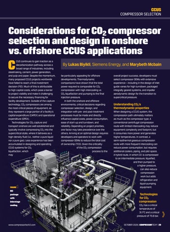
FIGURE IGC package with interstage cooling.
www.compressortech2.com
By Lukas Biyikli, Siemens Energy, and Marybeth Mcbain be particularly appealing for offshore developments. Thermodynamic comparisons have shown that the total power required is comparable for CO2 compression with high intercooling vs CO2 liquefaction and pumping to the final injection pressure. In both the onshore and offshore environments, critical decisions regarding compressor selection, design, and integration with pre- and post-treatment processes must be made and directly influence capital costs, power consumption, ease of start-up and turndown, and reliability. Depending on project priorities, one factor may take precedence over the others. Arriving at an optimal design requires developers and operators to work with compressor OEMs to reduce the total cost of ownership (TCO). Given the criticality of the CO2 compression process to the
overall project success, developers must select compressor OEMs with extensive experience – including in the design of inlet guide vanes for high turndown, packaged integrally geared systems, and impeller aerodynamic design for the transition to supercritical pressure.
Understanding CO2’s thermodynamic properties When designing a CCUS system, the compression path ultimately matters as much as the compressor type. A conventional centrifugal compression route with limited intercooling may reduce equipment complexity and footprint, but it consumes more power and generates higher temperatures. In contrast, a semi-isothermal gaseous compression route with more frequent intercooling can reduce power consumption, but requires additional coolers, piping, and plot space. A hybrid route, in which CO₂ is compressed to an intermediate pressure, liquefied, and then pumped to a higher pressure, can also reduce compression work but adds refrigeration and liquid-pumping equipment.
Technologies for CO2 compression CO2 has a critical temperature of 31.1°C and a critical pressure of 73.8 bar. OCTOBER 2026 | COMPRESSORTECH2 | 29
>
CCUS
COMPRESSOR SELECTION
OPERATIONAL ASPECT
SINGLE SHAFT CENTRIFUGAL
MULTI-SHAFT IGC
RECIPROCATING
Operating Flexibility
Operates between surge / stonewall regions. All impellers in casing at same speed (Ma limits). Must manage dense phase transition.
Longer start-up sequence due to multiple ASV’s.
More robust handling of high-density sCO2. Easier to start and stop. No surge control requirements.
Single casing with up to 10 impellers. Compact footprint without intercooling.
Larger package with interstage piping, oil systems, and several intercoolers. Footprint can be reduced by optimized baseplate arrangement.
Larger package due to pulsation bottles and piping between cylinder stages. Intercooling necessary due to packing and valve temp limits.
Up to 30% typical. IGVs may add 20-25% more range.
Up to 40%. Multiple IGVs can be added to the stages governing flow limit, thereby increasing turndown.
Up to 85% turndown with all cylinders single-acted or use of unloaders.
Higher due to later stages at elevated temperatures without the ability to intercool.
Lower due to the ability to intercool between stages.
Tends to be higher due to elevated temperature generated per cylinder/ stage.
Footprint and Weight
Turndown – Range and Mechanism (without speed variation)
Power Consumption
2
FIGURE Comparison of CO2 compression technologies.
Above that point, it enters the supercritical (sCO2) region, where it behaves as a dense compressible fluid with characteristics of both a gas and a liquid. The supercritical region creates design challenges for rotating equipment. Centrifugal compressors generally do not tolerate two-phase flow well. Reciprocating compressors are better at handling the changing compressibility factors in this transition region. Temperature management is particularly important. CO2 heats up rapidly during compression due to its real-gas behavior and high heat of compression. In practical terms, intercooling can reduce overall compression power by roughly 10–20%, depending on the configuration and pressure ratio. Multiple compressor technologies can be applied across the pressure ranges required for CO2 capture, transport, and storage. ■ Reciprocating compressors are typically used in CO2 applications with flows below 0.2 MTPA or where high turndown is required. They are also well-suited for high-pressure-ratio duties in the supercritical region because they can tolerate changes in CO2 compressibility. Operating flexibility is another advantage. Recip compressors can achieve turndown up to ~85% through cylinder unloading, speed variation, single-acting cylinders, and other control methods. Additionally, they offer straightforward start-up and multiple 30 | COMPRESSORTECH2 | OCTOBER 2026
load steps through individual cylinder operation. In dense-phase or supercritical service, cylinder valves can be designed for higher discharge densities. At the same time, interstage scrubbers are typically used in wet CO2 service to remove liquid dropout and protect valve performance. Reciprocating compressors are also well suited to modular, skid-mounted packages for smaller flows, particularly in upstream gas processing facilities where captured CO2 may be delivered to a common supercritical trunkline. For flow rates of 0.05–0.2 MTPA, packaged units can integrate the motor drive and pulsation bottles on a single frame, with additional stages added to meet higherpressure requirements. ■ Single-shaft centrifugal compressors are commonly applied in large-volume CO2 applications, including post-combustion capture from power generation, cement, and steel facilities, as well as offshore projects where footprint and weight are major constraints. Because CO2 has a relatively high molecular weight and density, centrifugal compressors can generate high head at comparatively low circumferential speeds. This differs from lighter gases such as hydrogen, which require much higher speeds for equivalent head. However, adding intercooling between the casings of the single-shaft compressors will help lower the total power requirements. The main advantages of single-shaft compressors are their small footprint, lower weight, and minimal interstage piping
requirements. These features are especially valuable for brownfield sites and offshore facilities. Their lower seal count per impeller is attractive compared with multi-shaft compressors, and noise can often be managed through casing and stator design. ■ M ulti-shaft centrifugal (integrally geared compressors) - Integrally geared compressors (IGCs) are often selected when minimizing power consumption is a priority. Their design allows multiple pinion shafts around a central bull gear, with each stage operating at an optimized speed. Because each impeller sits in its own volute casing, intercooling can be applied between stages, thereby lowering the process gas temperature and reducing the total compression work. The ability to adjust individual impeller diameters and pinion speeds allows IGCs to maintain higher stage efficiency as volumetric flow decreases with increasing pressure. IGCs also reduce the number of stages required compared with singleshaft units for raising from atmospheric to pipeline pressure. They are often controlled by movable inlet guide vanes (mIGVs), which provide efficient turndown without the cost of variable-speed drives (VSDs). Turndown is typically around 40% and can be increased by applying mIGVs to limiting stages.
Centrifugal pumps and liquefaction pathways An alternative to fully compressing CO2 in gaseous or supercritical form is to partially compress and cool the stream until it www.compressortech2.com
>
Trust Ebara Elliott Energy
for unparalleled expertise in LNG services. As a key partner for some of the world’s largest LNG projects, Ebara Elliott Energy’s cryogenic pumps and liquid expanders deliver maximum efficiency and process control in a wide variety of marine, land-based, floating, and small-scale liquefied natural gas applications. With a history of industry firsts, and a focus on advancing sustainable technologies, Ebara Elliott Energy is a partner you can trust.
Learn more about our contributions toward global energy sustainability at elliott-turbo.com.
Trusted Solutions for a Sustainable Future COMPRESSORS | STEAM TURBINES | P U M P S | GLOBAL SERVICE
CCUS
COMPRESSOR SELECTION
condenses into a liquid, then use pumps to raise it to pipeline or injection pressure. Because liquids are nearly incompressible, pumps require far less energy than compressors to increase pressure. The trade-off is the need for refrigeration or cryogenic compression, which requires cooling CO2 to approximately –20°C to –35°C, or lower depending on feed conditions and impurity levels. LNG has been considered for marine applications because of its availability as both fuel and cargo, while s CO2-based refrigerant cycles may offer footprint and commonality advantages in some cases. For offshore use, refrigerant compressors, booster compressors, and pumps must be marinized and designed for higher structural loads and modular integration. In summary, liquid pumping can reduce total energy consumption when high final pressures are required, particularly if the reduction in compression work outweighs the refrigeration duty. Pumps also offer mechanical advantages, are generally easier to maintain than large compressor trains, and avoid phase-boundary issues once the CO2 is fully condensed.
Onshore vs. offshore CO2 compression For onshore pipelines with “low” flow rates, gaseous compression may be suitable. However, for higher flows, supercritical CO2 represents the most efficient transport path because it reduces pressure drop per unit mass compared with gas-phase or twophase transport. There is often a breakover point at which supercritical pipeline transport with pumping requires less power and lower CAPEX than low-pressure gas-phase transport. In such cases, initial compression to supercritical pressure remains significant, but downstream booster stations can use sCO2 pumps at a lower power penalty. Offshore CO2 compression often necessitates different machinery than onshore gas/s CO2 pipelines. In certain offshore applications, it may be advantageous to use compressors to raise the captured CO2 product to an intermediate pressure or to the full s CO2 pressure (i.e., a 32 | COMPRESSORTECH2 | OCTOBER 2026
Compressor technologies present distinct trade-offs for onshore and offshore CCUS applications. hybrid pathway), thereby making it ready for injection into an offshore reservoir. Listed below are important process and technology considerations for a hybrid compression-liquefaction route in an offshore application. ■ F or any given CO2 compressor (IGC, single-shaft or reciprocating), finite element analysis (FEA) of the frame, auxiliary components, and nozzle loads must be evaluated with the dynamic motion specifications of the offshore facility. Even if the CO2 liquefaction route is selected, the machinery will still include a compression step from atmospheric capture pressure to the liquefaction pressure. ■ I GCs, with the advantages of optimized speed and intercooling between CO2 compression stages, face the design challenge of a high seal count and multiple stages connected by intercoolers and associated compressor nozzles. The nozzle loading for offshore units is higher, and each compressor package must deliver a more robust nozzle design. ■ Traditional refrigerants (RF1- and R-290-based) are suitable for the offshore refrigeration cycle. However, there may be cases where lessflammable alternative refrigerants with lower environmental risk is a better option. For systems with a coefficient of performance (COP) below 4, an s CO2-based refrigerant cycle using a small s CO2 compressor may warrant further consideration given its obvious commonality advantages. The risks, performance, and technology readiness of each cycle to deliver L CO2 at medium pressures (7-8 barg / 100–120 psig)
should be thoroughly evaluated. ■ The impact of non-condensable impurities in the captured CO2 stream should be evaluated to quantify their effect on liquefaction efficiency. Projectspecific CO2 disposal and injection specifications must also be reviewed to ensure the captured CO2 meets required quality and impurity limits for reservoir injection. ■ The effects of corrosive impurities on construction materials should be evaluated. This has been the known culprit of availability issues in multiple high-profile CO2 injection projects. ■ The performance and footprint for the LCO₂ tank pumps should be profiled to determine technology capabilities to deliver the full injection pressure of the offshore reservoir.
Conclusion Compressor technologies present distinct trade-offs for onshore and offshore CCUS applications. CAPEX and total power consumption are the primary factors influencing CO2 compressor selection for offshore CCUS projects. However, application-specific requirements such as modularity, turndown, operational flexibility, start-stop capability, and offshore footprint can also be decisive. The lowest-power routes are typically gaseous semi-isothermal compression or hybrid compression and liquefaction. In practice, the number of cooling stages often has a greater impact on total power consumption than compressor efficiency alone. Ultimately, appropriate compressor selection supports optimal energy performance, lower operating costs, and improved reliability. Early collaboration between project stakeholders and experienced CO2 compressor OEMs helps ensure the system is optimized to plant boundary conditions from the outset. CT2 REFERENCE: [1] Ergina, J., Bowman, T. “Improving CCUS Project Bankability Through Integrated CO2 Compression and Dehydration System Design”. Presented at Gastech 2025. September 10th, 2025. [2] McBain, M., Macleo, I., Biyikli, L., Husmann, L., Nguyen, D. “Evaluating CO2 Compression Machinery for Onshore and Offshore Applications”. Asia Turbomachinery & Pump Symposium. May 20th, 2026.
www.compressortech2.com
SMT
SOLAR® MOBILE TURBOMACHINERY
RELIABILITY − WHEN AND WHERE YOU NEED IT Solar Turbines offers mobile power plant solutions in two sizes − 5.7 MWe and 16.5 MWe − based on the technology of our proven Taurus™ and Titan™ gas turbines. Designed for easy transportation and relocation, our Solar ® Mobile Turbomachinery (SMT) products are lightweight, require minimal site setup, and can operate on a wide variety of fuels. Backed by over 60 years of experience, our SMT products are ready to meet all your field production needs or provide power on demand − anytime and anywhere.
SMT60 − 5.7 MWe
SMT130 − 16.5 MWe
• • •
• • • •
Fully-integrated single frame design Hydraulic leveling system Less than four-hour setup time
Fully-integrated dual frame design Hydraulic leveling system Less than 24-hour setup time Rapid alignment technology
Scan the QR Code or visit us at www.solarturbines.com
ONE STOP
SHOP
www.kbdelta.com 310-530-1539 Torrance, California USA info@kbdelta.com • sales@kbdelta.com
TAKING CARE OF ALL YOUR COMPRESSOR VALVE NEEDS.
7
24
hrs
days
Metallic Plates|Thermoplastics|Springs|Buttons|Poppets|Kits|Center Bolts|Pins|Lift Washers|O-Rings
HYDROGEN
GREENE TWEED
Hydrogen changes the ru As hydrogen moves from demonstration projects toward commercial deployment, compressor designers are discovering that many of the engineering assumptions developed for natural gas no longer apply. By Jack Burke
wear rates and material selection. “The audience should understand that there are major challenges that are really specific to hydrogen,” said Philippe Allienne, business development manager at Greene Tweed. “There are definitely some gaps in materials science that still need to be addressed.” Those gaps are becoming increasingly important as governments and industry invest in hydrogen production, transportation and storage infrastructure. Pipeline operators, industrial gas suppliers and equipment manufacturers are now developing compressors capable of pressures far exceeding those common in conventional natural gas service. Unlike methane, however, hydrogen often exposes the physical limits of materials that have performed reliably for decades.
Different gas; different compressor
IMAGE: KAWASAK
Kawasaki Heavy Industries’ demonstration facility for its centrifugal hydrogen compressor.
F
or more than 100 years, compressor technology has evolved around one fundamental assumption: the gas being compressed behaves much like natural gas. Engineers refined piston rings that could withstand decades of reciprocating service. Centrifugal compressor designers steadily increased impeller efficiencies. Seal manufacturers improved leakage control. Material scientists developed polymers capable of surviving ever higher pressures and temperatures. Hydrogen changes nearly all of those assumptions. Although the machines themselves remain recognizable, the gas inside them behaves very differently. Hydrogen’s exceptionally small molecular size, low viscosity, low density and unique thermodynamic properties influence virtually every aspect of compressor design—from impeller tip speeds and pressure ratios to seal performance,
36 | COMPRESSORTECH2 | OCTOBER 2026
The first misconception, according to Allienne, is assuming hydrogen behaves like any other process gas. It does not. Hydrogen’s molecular weight is only about one-eighth that of methane. Because centrifugal compressor performance depends heavily on gas density, dramatically lighter gases require significantly higher rotational speeds to achieve equivalent pressure ratios. That immediately complicates compressor design. “The low molecular weight has a direct impact,” Allienne explained. “You either need more stages or higher rotational speeds to reach the same pressure ratio.” Hydrogen also carries much less energy per unit volume than natural gas. To deliver the same energy, operators must move roughly three times more gas. That seemingly simple fact has enormous implications. Future hydrogen infrastructure will require substantially higher volumetric flow rates throughout production plants, www.compressortech2.com
HYDROGEN
GREENE TWEED
e rules for compression pipelines, storage facilities and fueling stations. For compressor manufacturers, higher flow rates frequently mean larger machines, additional compression stages or entirely different compressor architectures.
Speed barrier Among rotating equipment, centrifugal compressors face one of hydrogen’s most fundamental engineering obstacles. Compression ratio depends on impeller tip speed and on the molecular weight of the gas being compressed. With conventional hydrocarbons, existing metallic impellers provide adequate performance while remaining comfortably below their mechanical limits. Hydrogen narrows that margin considerably. Sebastien Kohler, senior scientist at Greene Tweed, explained that traditional closed impellers generally operate around 340 to 350 meters per second. Hydrogen applications ideally require tip speeds approaching 600 meters per second. “The issue is that if you go faster, eventually you reach burst speed,” Kohler
said. “Your impeller breaks.” Unfortunately, simply switching to stronger steel is not an option. Hydrogen embrittlement limits the use of many high-strength alloys that might otherwise provide the necessary mechanical performance. The challenge therefore becomes finding lighter materials capable of surviving extreme rotational loads without suffering hydrogen-related degradation. That search is driving renewed interest in advanced composite impellers. Unlike steel, carbon-fiber composites combine high strength with substantially lower density, allowing designers to increase rotational speed without proportionally increasing centrifugal loading. Composite impellers remain an emerging technology, but Kohler believes they illustrate how hydrogen is changing compressor design philosophy. “We demonstrated that it is possible,” he said. “The next challenge is understanding how to model these materials accurately in complex geometries.” Unlike metals, composite materials behave differently depending on fiber
THE NATURAL PROGRESSION WAUKESHA NATURAL GAS ALTERNATIVES
WAUKESHAENGINE.COM
orientation, manufacturing quality and loading direction. Those characteristics demand new finite element analysis methods capable of predicting three-dimensional stress states within highly complex impeller shapes.
A different challenge If centrifugal compressors struggle with aerodynamics, reciprocating compressors struggle with tribology. Hydrogen’s extremely low viscosity reduces the lubricating film available between moving surfaces. Components that experience modest wear in natural gas service may degrade much more rapidly in hydrogen. “In reciprocating compressors, low viscosity can generate much higher wear rates,” Allienne said. “Piston rings and rider bands are among the components most affected.” Pressure compounds the problem. Many hydrogen mobility and storage applications now target discharge pressures approaching 700 bar, with some development work extending toward 900 bar. Those operating conditions exceed
>
HYDROGEN
GREENE TWEED
the practical limits of several materials commonly used in conventional compressor components. Traditional PTFE formulations, long regarded as industry workhorses for sealing and wear applications, begin approaching their practical operating envelope under those conditions, requiring engineers to investigate new polymer systems capable of maintaining structural integrity at higher temperatures and pressures.
Rapid gas decompression Ask engineers to identify hydrogen’s greatest materials challenge and many will immediately mention Rapid Gas Decompression (RGD) also named explosive decompression. The phenomenon has become almost synonymous with highpressure hydrogen service, particularly in discussions surrounding elastomer seals. Allienne and Kohler agree it deserves attention—but they caution that it is frequently misunderstood. Explosive decompression occurs when hydrogen diffuses into a polymer under high pressure and then expands rapidly as pressure is released. If the gas cannot escape quickly enough, internal pressure builds within the material, creating microcracks, blisters or, in severe cases, catastrophic failure. “It’s really a pressure-transient phenomenon,” Kohler explained. “The material isn’t necessarily failing because hydrogen is attacking it chemically. It’s the rapid expansion of gas trapped inside the material that creates the damage.” That distinction matters as it makes elastomers more vulnerable to RGD issues compared to plastics and composites that will generally better resist RGD because of higher tensile strength, lower chain mobility, and lower gas permeability
Quality of manufacturing matters For composite materials, Kohler said, processing quality can be just as important as chemistry. Carbon-fiber reinforced PEEK laminates exhibit inherently low hydrogen permeability, but only if they are manufactured with excellent consolidation. Voids, porosity or 38 | COMPRESSORTECH2 | OCTOBER 2026
poor fiber-to-matrix bonding create leakage paths that allow hydrogen to accumulate. “If you have a badly consolidated laminate with porosity or a poor fiber-tomatrix interface, those become leakage paths,” Kohler said. “Manufacturing quality becomes absolutely essential.”
Temperature works against you Pressure is only part of hydrogen’s challenge. Temperature introduces another complication that many engineers unfamiliar with hydrogen overlook. Unlike natural gas, hydrogen has a negative Joule-Thomson coefficient over many operating conditions. Instead of cooling during expansion, hydrogen can actually become warmer. “That’s the opposite of gases that compressor engineers are accustomed to working with,” Allienne noted. Higher gas temperatures translate directly into higher component temperatures. Piston rings, rider bands, bearings and seals already experience significant frictional heating. Add elevated gas temperatures, and components can approach the upper limits of conventional engineering polymers much sooner than expected. Historically, many compressor wear components have relied on PTFE formulations because they combine low friction with excellent chemical resistance. Hydrogen’s operating envelope is beginning to expose their limitations. Industry development is increasingly focused on applications approaching 700 bar for heavy-duty fueling and storage, with some projects evaluating pressures near 900 bar. At those pressures, traditional PTFE materials begin reaching practical operating limits, particularly when combined with elevated temperatures and repeated pressure cycling. The industry is therefore pursuing materials capable of maintaining stiffness and mechanical integrity at temperatures well beyond those tolerated by conventional polymers. Cross-linked PEEK materials represent one example.
Unlike conventional thermoplastics that gradually soften as temperature rises above their glass transition temperature, cross-linked formulations retain structural integrity over a much broader operating range. “Instead of melting, the material behaves more like a thermoset,” Allienne explained, allowing it to maintain load-bearing capability at temperatures where traditional materials begin losing mechanical strength.
Tribology moves to center stage While hydrogen receives attention for embrittlement and permeability, Kohler believes another discipline deserves equal recognition: tribology. Simply put, hydrogen is a poor lubricant. Its extremely low viscosity makes it difficult to maintain protective films between moving components. For reciprocating compressors, that increases reliance on the wear characteristics of the materials themselves. The result is renewed interest in selflubricating composites. Carbon-filled PEEK materials have already found widespread use in bearings, bushings and wear rings because the carbon reinforcement provides inherent lubricity while resisting galling and seizure. “It has the huge advantage of being a non-seizing, non-galling material,” Kohler said. “It also tends to protect the shaft much better than traditional metallic bearings.” Testing conducted under upset conditions—including dry-running and temporary loss of lubrication—has shown dramatically lower wear rates compared with conventional metallic bearing materials, he said. Those same tribological properties could prove valuable for piston rings, rider bands and labyrinth seal components operating in hydrogen service. Rather than relying solely on lubricating films, engineers increasingly want materials capable of surviving direct contact without catastrophic damage.
A different duty cycle Hydrogen infrastructure introduces another variable largely unfamiliar to www.compressortech2.com
HYDROGEN
GREENE TWEED
traditional natural gas systems. Many future compressor stations may not operate continuously. Electrolyzers powered by renewable energy produce hydrogen intermittently, following fluctuations in wind and solar generation. As a result, compressors may cycle on and off far more frequently than conventional pipeline machines. Repeated thermal expansion and contraction, combined with rapid pressure changes, creates additional fatigue mechanisms. Instead of accumulating operating hours, components accumulate pressure cycles. That distinction affects seals, bearings, polymer wear components and even metallic structures. Designing for intermittent duty therefore becomes as important as designing for pressure. Materials must tolerate thousands—or potentially millions—of start-stop cycles without losing dimensional stability or
mechanical performance. Perhaps the most interesting aspect of the discussion with Allienne and Kohler was what they identified as the industry’s remaining knowledge gaps. Contrary to popular perception, they did not point first to stronger metals or higherpressure seals. Instead, they highlighted modeling. Composite impellers illustrate the challenge. Manufacturing technology has progressed rapidly enough to produce viable demonstrators. Understanding precisely how those complex composite structures behave under combined centrifugal, thermal and pressure loading remains an active area of research. Traditional finite element methods were developed largely for isotropic metallic materials. Composite structures introduce directional properties, layered architectures and complex three-dimensional stress
distributions that require different analytical approaches. Improved predictive modeling could significantly accelerate development of future hydrogen compressor components by reducing the need for expensive fullscale testing. As Allienne summarized near the conclusion of the discussion, the industry’s understanding of hydrogen has advanced considerably, but important gaps remain. Closing those gaps will require continued collaboration among compressor manufacturers, materials scientists and end users as hydrogen infrastructure moves from demonstration projects to commercialscale deployment. For the compression industry, the lesson is clear: the next breakthroughs in hydrogen service may come not from entirely new compressor concepts, but from the materials that allow familiar machines to operate reliably in an unfamiliar environment. CT2
ProfloTM - Complete Compressor Lubrication Monitoring & Shutdown Protection
ProfloTM PF2 • Programmable shutdown device that monitors lubricant flow in divider block metering systems. Visual trend graphs, configurable relay outputs, on-board diagnostics and wireless communication. ProfloTM Jr.2 • Monitoring device that delivers reliable shutdown protection for your compressor, based on the proven timing of the divider block system. ProfloTM Cycle Switch • Single-pole, single-throw magnetic reed switch that sends a dry-contact signal to any PLC-style control panel or directly to the lubrication monitor, such as the ProfloTM PF2.
Ready to protect your compressor and reduce downtime? Scan here
Magnet Assembly • All devices share the same robust magnet assembly, meaning easy interconnectivity and a single spare part for inventory. Certification • All devices are Hazardous Location certified* for Class I / Div I / Zone 1 or better according to: *See Instruction Manual of each device for full certification information. Proven Solutions for the Global Compression Industry www.CPIcompression.com CPI by Howden is a Chart Industries Company
CIP Proflo Ad_CompressorTech2_Half pg_mm.indd 1
9/18/2026 8:52:46 AM
INDUSTRY TRENDS ESG
Companies are using a different language, but emissions reductions, safety and reliability remain key.
Moving b Y
ears ago, I worked for a magazine that devoted an annual issue to the biggest story, trend or company of the previous 12 months. One year, the title went to the BRIC countries — Brazil, Russia, India and China. At the time, they were the markets every company talked about, planned for and invested in.
Times change Five years ago, ESG occupied a similar place in the energy industry’s vocabulary. It was nearly impossible to attend an energy conference, read an annual report or listen to an earnings call without hearing those three letters repeated over and over again. Environmental, social and governance initiatives became a defining theme throughout the industry. Pipeline operators published glossy ESG reports, executives highlighted sustainability targets during earnings calls and companies hired ESG specialists to oversee expanding reporting requirements. Today, the acronym is surprisingly difficult to find. Investor presentations that once devoted entire sections to ESG now emphasize operational excellence, methane intensity, reliability, emissions reduction, capital discipline and responsible operations. Reports increasingly carry titles such as “Sustainability Report,” “Impact Report” or “Responsible Business Report” instead of “ESG Report.” Research from The Conference Board illustrates how quickly the terminology has changed: among S&P 100 companies, the percentage using “ESG” in report titles fell from 40% in 2023 to 25% in 2024, and only 6% of reports published in 2025 used the term. Yet 87% of S&P 500 companies continued to disclose climaterelated targets. Late last year, The Washington Post reported that mentions of ESG in corporate earnings calls had fallen to about one-third 40 | COMPRESSORTECH2 | OCTOBER 2026
www.compressortech2.com
INDUSTRY TRENDS ESG
g beyond the ESG label of their 2021 peak, citing energy analyst Nathaniel Bullard. The newspaper also found evidence of something more substantive than rebranding: some companies were scaling back or abandoning climate commitments. Jason Bordoff of Columbia University’s Center on Global Energy Policy said pressure on companies to publicly demonstrate net-zero plans had eased.
Has ESG fallen out of favor? The answer appears to be yes — if the question is about branding. If the question is about environmental performance itself, the answer is more complicated. A change in language, not necessarily priorities GPA Midstream sees much the same
trend among its members. The association said environmental stewardship, safety, reliability and workforce development remain important priorities, but companies increasingly communicate them through sustainability reporting and operational metrics. One industry source told GPA Midstream that their company had deliberately shifted from ESG to sustainability, joking that ESG had become a “four-letter word.” The label had acquired a negative connotation even though many of the concepts associated with it remained part of the company’s thinking. That may be the distinction that matters most: The terminology has changed more dramatically than many of the underlying activities.
REBUILD RE-ENGINEER REIMAGINE Beyond overhaul. Built for what’s next.
Get M o r e F r o m Yo ur In d u st r i a l Asse ts. BLACKSTO N E IN DUSTR IA L .CO M
GPA Midstream said companies continue to prioritize emissions management and safety, but are changing how those efforts are described and organized. Environmental initiatives increasingly fall under sustainability or operational excellence, while governance issues may appear separately in proxy disclosures and other corporate reporting. Review recent presentations from major North American midstream companies and the pattern is evident. Executives spend less time discussing ESG ratings or sustainability frameworks and considerably more time discussing measurable operating performance: methane emissions intensity, leak detection and repair, compressor modernization, electric compression,
>
INDUSTRY TRENDS ESG
lower-emissions engines, reliability improvements, operational efficiency and responsible capital allocation. Those initiatives might have been presented under the ESG umbrella several years ago. Today, they are increasingly discussed as business fundamentals. For compression operators, that evolution makes practical sense. Reducing methane emissions also reduces lost product. Replacing older compressor engines can improve emissions performance while reducing maintenance
MPLX’s Bluestone natural gas plant in Pennsylvania is the first facility of its kind ever to achieve the ENERGY STAR Challenge for Industry, which requires facilities to reduce their energy intensity by 10% within a five-year period.
requirements and fuel consumption. Electrification can lower emissions while improving operating economics where adequate power is available. Increasingly, those investments can stand on their business merits without an ESG label.
Political headwinds accelerated the transition The terminology shift did not occur in isolation. ESG became one of the most politically contentious topics in corporate America, prompting many companies to reconsider how they described long-standing sustainability efforts. The Conference Board found that many organizations intentionally replaced “ESG” with less politically charged terms such as sustainability, resilience or impact while leaving many of the underlying programs intact. The change cannot be dismissed entirely as rebranding, however. Some companies have scaled back climate commitments, and federal policy has moved decisively away from several climate-related mandates. But in midstream, many of the initiatives once presented as ESG have survived because they also address operational problems. At the regulatory level, the landscape has shifted substantially. The U.S. Environmental Protection Agency has begun reconsidering several requirements affecting oil and natural gas operations. In April, EPA finalized changes to portions of the 2024 www.compressortech2.com
>
What if your next compression challenge could help shape the industry’s next research question?
Your compression challenges are where Gas Machinery Research Council (GMRC) research begins. Bring what your organization knows. Gain from what the industry has learned. Help advance the solutions that come next.
Built with and used by the gas compression industry. Become a GMRC Member.
gmrc.org/membership
INDUSTRY TRENDS ESG
methane regulations and is conducting a broader reconsideration of those rules. EPA has separately proposed changes to air-toxics standards affecting natural gas transmission and storage facilities and proposed substantially reducing greenhouse-gas reporting requirements for numerous industries. Other federal climate policies have also retreated. Congress overturned the methane Waste Emissions Charge in 2025, while the Securities and Exchange Commission has proposed rescinding its climate-related disclosure rules. Yet emissions management has hardly disappeared from the midstream agenda. In some ways, that makes the industry’s continued investment more revealing. If regulatory pressure and ESG branding are both receding, environmental initiatives increasingly have to justify themselves through reliability, efficiency, safety, risk reduction or economics.
Midstream cannot simply move on
initiatives no longer
From ESG to operational excellence
Perhaps the biggest change is that many
need Environmental, Social and Governance branding to justify investments.
PHOTO CREATED BY CHAT GPT
Unlike some sectors where ESG discussions centered heavily on reputation, environmental performance remains inseparable from daily operations in the midstream industry. Compressor stations remain subject to
environmental
safety performance, workforce development and risk management among the industry’s primary environmental and operational priorities. What’s striking about that list is how difficult it is to separate the “ESG” priorities from the operational ones. Emissions reduction can involve compressor modernization. Digital technology can improve both emissions detection and equipment reliability. Infrastructure modernization can improve efficiency, availability and environmental performance. Workforce development affects whether companies have the people capable of operating increasingly sophisticated equipment. Whether companies describe those investments as ESG or operational excellence has little effect on the engineering challenges involved.
air-emissions and methane requirements. Pipeline operators continue investing in leak detection. LNG developers operate in a global market where carbon intensity can influence commercial decisions. Electrification, lower-emissions engines, CCUS and digital optimization remain active areas of investment. GPA Midstream’s view of the industry’s next five to 10 years reinforces that point. The association identified emissions reduction, operational efficiency, reliability and resilience, infrastructure modernization, effective utilization of digital technologies,
44 | COMPRESSORTECH2 | OCTOBER 2026
Perhaps the biggest change is that many environmental initiatives no longer require ESG branding to justify investment. Methane reduction improves product recovery. Predictive maintenance improves reliability. Compressor upgrades can lower operating costs. Digital monitoring can reduce unplanned downtime. Increasingly, those projects compete for capital on operational and financial performance rather than ESG scores. Five years ago, ESG often functioned as a separate corporate initiative. Today, many of its most practical elements have become embedded in engineering, operations and capital planning. GPA Midstream’s list of priorities — emissions, efficiency, reliability, modernization, digital technology, safety, workforce and risk management — could just as easily describe the agenda at an operations meeting as the contents of a sustainability report. Perhaps that’s the real measure of what has changed. ESG may have become a four-letter word. But many of the ideas once collected beneath those three letters haven’t disappeared. They’ve become part of the business. CT2 www.compressortech2.com
TECHNOLOGY ORC SYSTEMS
Turboden systems will convert compressor station exhaust into grid power while creating a potential model for midstream operators. By Jack Burke
Tallgrass expands waste-heat recovery program with three additional ORC power projects
T
allgrass is expanding its use of wasteheat-to-power technology across its natural gas pipeline network, selecting Turboden to supply three additional Organic Rankine Cycle (ORC) systems that will generate electricity from gas turbine exhaust at compressor stations in Ohio and Indiana. The new installations, located in Columbus and Chandlersville, Ohio, and St. Paul, Indiana, follow a previously announced project at Tallgrass’ Washington Court House compressor station in Fayette County, Ohio. Together, the four projects will provide 46.1 MW of power generation capacity by capturing heat that would otherwise be released to the atmosphere.
Large deployment For the midstream sector, the projects represent one of the largest deployments of waste-heat recovery technology at pipeline compressor stations in North America and highlight growing interest in extracting additional value from existing gas transportation infrastructure. According to Turboden, each of the new systems is expected to generate approximately 10 MW of electricity by utilizing exhaust energy from gas turbinedriven compressor units. The output is determined by several factors, including turbine size, exhaust temperature and exhaust flow rates. “The approximately 10 MW output at Tallgrass compressor stations is primarily 46 | COMPRESSORTECH2 | OCTOBER 2026
determined by the gas turbine exhaust characteristics: turbine size or type, exhaust temperature and mass flow rate,” said Dan Nadav, who leads business development and project origination at Turboden. “In these applications, Turboden ORC systems are typically matched to gas turbines producing exhaust in the 800-1,100 F range with sufficiently high flow rates to deliver multimegawatt thermal input.”
Emissions-free electricity Nadav noted that the technology is not limited to high-temperature turbine exhaust streams. ORC systems can also recover energy from lower-temperature sources, including gas engines and fuel cells operating in the 300-700 F range. The projects are designed to generate emissions-free electricity without consuming additional fuel or water. At the Tallgrass facilities, the recovered power
“The ORC system is designed as a zero-impact retrofit, requiring no modification...” DAN NADAV, leads business development and project origination at Turboden.
will be exported to local utility grids rather than used at the compressor stations themselves. “Turboden ORC systems at compressor stations can be configured either to serve on-site electric loads or to export power via a grid interconnection,” Nadav said. “At the Tallgrass projects, including the Washington Court House station and three others, the electricity generated by the ORC units is exported to the grid.” The company has deployed a different configuration elsewhere. At the Dahshur compressor station in Egypt, ORC-generated electricity is used on-site to power electric-driven compressors, effectively creating additional compression capacity without additional fuel consumption.
Impact on existing systems A key consideration for pipeline operators evaluating waste-heat recovery systems is their impact on existing compression equipment. According to Nadav, the Tallgrass installations are designed as retrofits that do not require modifications to the compressor packages or gas turbines. “The ORC system is designed as a zeroimpact retrofit, requiring no modification to the gas turbine-driven compressor package,” he said. “A diverter valve routes exhaust to the waste heat recovery unit without disrupting turbine operation or maintenance practices.” Additional backpressure on the turbine is www.compressortech2.com
TECHNOLOGY ORC SYSTEMS
entered service in mid-May, making it too early for Turboden to provide long-term operating data. However, the performance of the first project will be closely watched by midstream operators seeking to improve efficiency and reduce emissions without altering core compression operations.
A Turboden Organic Rankine Cycle (ORC) system.
minimal and managed through the design of the waste heat recovery unit, he added.
be supported by Turboanalytics, Turboden’s cloud-based monitoring platform that uses artificial intelligence for anomaly detection, predictive maintenance and performance forecasting.
Addressing electricity demand The technology works by transferring thermal energy from turbine exhaust into an organic working fluid with a lower boiling point than water. The vaporized fluid drives a turbinegenerator set before being condensed and returned to the system in a closed loop. Beyond the power-generation benefits, Tallgrass and Turboden see the projects as a way to help address growing electricity demand while improving the efficiency of existing infrastructure. The systems will also
Tallgrass operations Tallgrass operates more than 10,000 miles of energy infrastructure, including the Rockies Express Pipeline, Ruby Pipeline, Trailblazer Pipeline and Tallgrass Interstate Gas Transmission system. The company has increasingly emphasized projects that combine natural gas infrastructure with power generation and carbon management initiatives. The Washington Court House installation
Optimizing assets As pipeline companies face growing pressure to optimize existing assets, wasteheat recovery may offer an increasingly attractive opportunity. Compressor stations operate around the clock and generate substantial amounts of thermal energy, creating a potentially large untapped resource for power generation. If the Tallgrass installations perform as expected, they could provide a blueprint for broader adoption across the North American midstream sector, where hundreds of gas turbine-driven compressor stations continue to vent valuable heat energy into the atmosphere. CT2
D I D YO U K N OW? WE OFFER CONSTRUCTION EQUIPMENT MARKET RESEARCH ON NORTH AMERICA SERVICES ON NORTH AMERICA INCLUDE: ■ Market size information and 5-year forecasts ■ Sales & production data ■ Annual reviews and monthly market updates ■ Detailed research reports ■ Conferences & webinars ■ Analyst calls and bespoke briefings ■ Private client research capabilities
For further information contact:
mail@offhighwayresearch.com
GAS LINES
COMPANY NEWS
GREENE TWEED BENCHMARK
MONITORING GOVERNMENT SPEED ACT UPDATE
A KHL Group publication
BRAZIL DOUBLES LNG
CORNERSTONES
OF COMPRESSION www.compressortech2.com JANUARY 2026
CORNERSTONES COROLLARY: EVOLUTION OF PIPELINES AND COMPRESSOR STATIONS The Cornerstones of Compression series has highlighted many significant products over more than 160 years of continuous progress. This is the sixth of seven (formerly six) Cornerstones of Compression corollary articles that provide a look the evolution of natural gas pipelines and compressor stations. By Norm Shade
Xxxxxxxxxxxxxxxxxx
HORIZONTAL GAS ENGINE
VERTICAL GAS ENGINE
HORIZONTAL GAS ENGINECOMPRESSOR
HORIZONTAL BELT-DRIVEN COMPRESSOR
HORIZONTAL STEAM ENGINECOMPRESSOR
STEAM TURBINE
TOTAL UNITS
0 62 0 0 0 0 0 0 0 0 1
0 0 0 0 0 0 2 0 0 0 0
1 20 0 0 0 70 0 11 0 0 0
0 12 2 1 4 0 0 0 0 52 0
0 0 0 0 0 0 0 0 6 3 0
0 0 0 0 0 0 0 0 0 0 0
1 94 2 1 4 70 2 11 6 55 1
up to that time. The stations included gas gathering and boosting, natural gasoline production, and gas transmission services, ranging in size from 50 to 22,025 hp (37 to 16,424 kW). There were 411 units in total, and the variation in equipment was impressive. The majority of the engines and compressors were produced by companies located in Pennsylvania or New York, which were prevalent in early air compressor and gas engine and compressor manufacture. The rest came from companies in the industrial midwestern states of Ohio and Wisconsin.
Xxxxxxxxxxxxxxxxxxxx
GAS LINES
REGAL REXNORD
0 1 0 0 0 0 0 0 0 0 64
www.compressortech2.com
1
0
0
1
76 0 0 0 1
0 0 0 0 0
9 1 0 0 0 0 0 0 7 26
0 0 0 0 0 0 0 1 0 1
86 1 2 3 1 24 6 25 15 411
EVOLUTION OF 0 5 19 0 0 8 PIPELINES 18 217 85
the evolution of natural gas pipelines and compressor stations. By Norm Shade
Xxxxxxxxxxxxxxxxxx R
>
ecent issues of Cornerstones of Compression articles described the gas engines and compressors at sixteen early compressor stations of the Ohio Fuel Gas Company, which was organized in 1902. The equipment covered a wide range of ratings and was provided by a number of manufacturers primarily from Ohio and western Pennsylvania, which is where oil and gas production boomed at the time.
JANAURY 2026 | COMPRESSORTECH2 | 49
TABLE
to minimize channel resonance, maximize accuracy.
MANUFACTURER
GAS LINES
COMPANY NEWS
BRAZIL DOUBLES LNG
GREENE TWEED BENCHMARK
Allis Chalmers Bessemer Blaisdell Bury Carter Clark Climax Cooper Hamilton Ingersoll-Rand Jacobson LaidlawDunn-Gordon National Transit Nordberg Rathburn Jones Reeves Strait Snow Waukesha Westinghouse Worthington Totals
REGAL REXNORD RECERTIFICATION EXPANSION
CORNERSTONES
www.compressortech2.com JANUARY 2026
the evolution of natural gas pipelines and compressor stations. By Norm Shade
Xxxxxxxxxxxxxxxxxx ecent issues of Cornerstones of Compression articles described the gas engines and compressors at sixteen early compressor stations of the Ohio Fuel Gas Company, which was organized in 1902. The equipment covered a wide range of ratings and was provided by a number of manufacturers primarily from Ohio and western Pennsylvania, which is where oil and gas production boomed at the time. TABLE
The largest early natural gas pipeline company, Hope Natural Gas Company, was organized in 1899, operating in West Virginia and western Pennsylvania. Among the archives at the Coolspring Power Museum is a 1930 notebook that documents the history and the engine and compressor inventory of each of the 86 compressor stations that made up the Hope Natural Gas Company and their subsidiaries Reserve Gas Company and Hope Construction & Refining Company
1 Hope Natural Gas Co. Engines and Compressors By Manufacturer.
up to that time. The stations included gas gathering and boosting, natural gasoline production, and gas transmission services, ranging in size from 50 to 22,025 hp (37 to 16,424 kW). There were 411 units in total, and the variation in equipment was impressive. The majority of the engines and compressors were produced by companies located in Pennsylvania or New York, which were prevalent in early air compressor and gas engine and compressor manufacture. The rest came from companies in the industrial midwestern states of Ohio and Wisconsin.
Readership survey MANUFACTURER Allis Chalmers Bessemer Blaisdell Bury Carter Clark Climax Cooper
HORIZONTAL GAS ENGINE
VERTICAL GAS ENGINE
HORIZONTAL GAS ENGINECOMPRESSOR
HORIZONTAL BELT-DRIVEN COMPRESSOR
HORIZONTAL STEAM ENGINECOMPRESSOR
STEAM TURBINE
TOTAL UNITS
0 62 0 0 0 0 0 0 0 0 1
0 0 0 0 0 0 2 0 0 0 0
1 20 0 0 0 70 0 11 0 0 0
0 12 2 1 4 0 0 0 0 52 0
0 0 0 0 0 0 0 0 6 3 0
0 0 0 0 0 0 0 0 0 0 0
1 94 2 1 4 70 2 11
0
0
0
1
0
0
1
1 0 0 0 0 0 0 0 0 64
0 0 2 3 0 0 6 5 0 18
76 0 0 0 1 19 0 19 0 217
0 0 0 0 0 5 0 0 8 85
9 1 0 0 0 0 0 0 7 26
0 0 0 0 0 0 0 1 0 1
86 1 2 3 1 24 6 25 15 411
Xxxxxxxxxxxxxxxxxxxx
NOW!
SUBSCRIBE
R
The entire inventory by manufacturer and type of equipment is shown in Table 1. The earliest machines were 85 belt-driven horizontal compressors. The majority, 52, were manufactured by Ingersoll-Rand, which adapted their extensive line of air compressors for natural gas and oil field
Demand booming, challenges remain Jacobson RECERTIFICATION LaidlawEXPANSION Dunn-Gordon
National Transit Nordberg Rathburn Jones Reeves Strait Snow Waukesha Westinghouse Worthington Totals
www.compressortech2.com
CORNERSTONES EVOLUTION OF PIPELINES
6 applications. Bessemer manufactured 12 EXECUTIVE Q&A 55 of these units, with the rest supplied by six 1
HOERBIGER’S other companies as shown in Table 1. Most of these horizontal compressors AREK were belt-driven by 62 Bessemer horizontal DYRDOL gas engines. In addition, 18 were belt-driven by vertical gas engines manufactured by Waukesha, Westinghouse and several other companies. Interestingly, one large IngersollRand horizontal reciprocating compressor was belt-driven by a Westinghouse steam turbine. As indicated in Table 1, over half of Hope’s fleet were horizontal gas engine
EURO REPORT TAP EXPANDS CAPACITY
>
JANAURY 2026 | COMPRESSORTECH2 | 49
KN-22-90 JANUARY-FEBRUARY 2026
www.constructionbriefing.com A KHL Group publication
NOW ES INCLUD
CV-72
EXCLU INTER SIVE VIEW
LiuGon Luo
g’s Presid Guobin g
MINING AND QUARRYING
COLD ENOUGH FOR YOU?
TRUMP’S TARIFFS
How automation is reshaping the sector
Inside the challenge of building in Antarctica
Analysing the impact of the US trade policy
■ Insightful Magazine ■ Weekly Newsletters ■ Daily Briefing ■ Comprehensive Website
Contact us now for information! 1-800-264-5950 info@kienediesel.com www.kienediesel.com
HORIZONTAL GAS ENGINECOMPRESSOR
HORIZONTAL BELT-DRIVEN COMPRESSOR
HORIZONTAL STEAM ENGINECOMPRESSOR
STEAM TURBINE
TOTAL UNITS
0 0 0 0 0 0 2 0 0 0 0
1 20 0 0 0 70 0 11 0 0 0
0 12 2 1 4 0 0 0 0 52 0
0 0 0 0 0 0 0 0 6 3 0
0 0 0 0 0 0 0 0 0 0 0
1 94 2 1 4 70 2 11 6 55 1
0
0
0
1
0
0
1
1 0 0 0 0 0 0 0 0 64
0 0 2 3 0 0 6 5 0 18
76 0 0 0 1 19 0 19 0 217
0 0 0 0 0 5 0 0 8 85
9 1 0 0 0 0 0 0 7 26
0 0 0 0 0 0 0 1 0 1
86 1 2 3 1 24 6 25 15 411
www.compressortech2.com
The Cornerstones of Compression series has highlighted many significant products over more than 160 years of continuous progress. This is the sixth of seven (formerly six) Cornerstones of Compression corollary articles that provide a look
Hamilton REGAL REXNORD Ingersoll-Rand
WE DO SPECIALS! Flanged Double Block & Bleed Special Materials · Cryogenic Ultra High Pressure and more . . .
VERTICAL GAS ENGINE
0 62 0 0 0 0 0 0 0 0 1
up to that time. The stations included gas gathering and boosting, natural gasoline production, and gas transmission services, ranging in size from 50 to 22,025 hp (37 to 16,424 kW). There were 411 units in total, and the variation in equipment was impressive. The majority of the engines and compressors were produced by companies located in Pennsylvania or New York, which were prevalent in early air compressor and gas engine and compressor manufacture. The rest came from companies in the industrial midwestern states of Ohio and Wisconsin.
Xxxxxxxxxxxxxxxxxxxx
NOW!
The entire inventory by manufacturer and type of equipment is shown in Table 1. The earliest machines were 85 belt-driven horizontal compressors. The majority, 52, were manufactured by Ingersoll-Rand, which adapted their extensive line of air compressors for natural gas and oil field
CORNERSTONES EVOLUTION OF PIPELINES
applications. Bessemer manufactured 12 EXECUTIVE Q&A of these units, with the rest supplied by six
HOERBIGER’S other companies as shown in Table 1. Most of these horizontal compressors AREK were belt-driven by 62 Bessemer horizontal DYRDOL gas engines. In addition, 18 were belt-driven by vertical gas engines manufactured by Waukesha, Westinghouse and several other companies. Interestingly, one large IngersollRand horizontal reciprocating compressor was belt-driven by a Westinghouse steam turbine. As indicated in Table 1, over half of Hope’s fleet were horizontal gas engine
EURO REPORT TAP EXPANDS CAPACITY
CORNERSTONES COROLLARY: EVOLUTION OF PIPELINES AND COMPRESSOR STATIONS
available.
continuous, on-line pressure monitoring.
HORIZONTAL GAS ENGINE
Demand booming, challenges remain
MONITORING GOVERNMENT SPEED ACT UPDATE
• Compact design. • 316 stainless versions • Dual-port versions for
The largest early natural gas pipeline company, Hope Natural Gas Company, was organized in 1899, operating in West Virginia and western Pennsylvania. Among the archives at the Coolspring Power Museum is a 1930 notebook that documents the history and the engine and compressor inventory of each of the 86 compressor stations that made up the Hope Natural Gas Company and their subsidiaries Reserve Gas Company and Hope Construction & Refining Company
1 Hope Natural Gas Co. Engines and Compressors By Manufacturer.
Readership survey
OF COMPRESSION
• Pressures to 6000psi, temperatures to 500°F. • Short, straight flow path
CORNERSTONES
OF COMPRESSION
over more than 160 years of continuous progress. This is the sixth of seven (formerly six) Cornerstones of Compression corollary articles that provide a look
EURO REPORT TAP EXPANDS CAPACITY
SPEED ACT UPDATE
CORNERSTONES COROLLARY: EVOLUTION OF PIPELINES AND COMPRESSOR STATIONS
HOERBIGER’S AREK DYRDOL
0
0 0 2 3 0
MONITORING GOVERNMENT
The Cornerstones of Compression series has highlighted many significant products
EXECUTIVE Q&A
0
0 19 5 CORNERSTONES 6 0 0
GREENE TWEED BENCHMARK
www.compressortech2.com JANUARY 2026
Demand booming, challenges remain RECERTIFICATION EXPANSION
COMPANY NEWS
BRAZIL DOUBLES LNG
NOW!
The entire inventory by manufacturer and type of equipment is shown in Table 1. The earliest machines were 85 belt-driven horizontal compressors. The majority, 52, were manufactured by Ingersoll-Rand, which adapted their extensive line of air compressors for natural gas and oil field applications. Bessemer manufactured 12 of these units, with the rest supplied by six other companies as shown in Table 1. Most of these horizontal compressors were belt-driven by 62 Bessemer horizontal gas engines. In addition, 18 were belt-driven by vertical gas engines manufactured by Waukesha, Westinghouse and several other companies. Interestingly, one large IngersollRand horizontal reciprocating compressor was belt-driven by a Westinghouse steam turbine. As indicated in Table 1, over half of Hope’s fleet were horizontal gas engine
A KHL Group publication
KIENE Indicator Valves for Compressor Analysis
The largest early natural gas pipeline company, Hope Natural Gas Company, was organized in 1899, operating in West Virginia and western Pennsylvania. Among the archives at the Coolspring Power Museum is a 1930 notebook that documents the history and the engine and compressor inventory of each of the 86 compressor stations that made up the Hope Natural Gas Company and their subsidiaries Reserve Gas Company and Hope Construction & Refining Company
1 Hope Natural Gas Co. Engines and Compressors By Manufacturer.
MANUFACTURER
Allis Chalmers Bessemer Blaisdell Bury Carter Clark Climax Cooper Hamilton Ingersoll-Rand Jacobson LaidlawDunn-Gordon National Transit Nordberg Rathburn Jones Reeves Strait Snow Waukesha Westinghouse Worthington Totals
SUBSCRIBE
TABLE
A KHL Group publication
ecent issues of Cornerstones of Compression articles described the gas engines and compressors at sixteen early compressor stations of the Ohio Fuel Gas Company, which was organized in 1902. The equipment covered a wide range of ratings and was provided by a number of manufacturers primarily from Ohio and western Pennsylvania, which is where oil and gas production boomed at the time.
SUBSCRIBE
R
Readership survey
C O N T E N T Y O U R W AY, S U B S C R I B E T O D AY
www.khl.com/free-subscription
ent,
JANAURY 2026 | COMPRESSORTECH2 | 49
>
BURCKHARDT
ACQUISITION
Deal adds compact, modular compression systems and
Fornovo Gas acquisition broadens Burckhardt Compression’s reach
expands
A Fornovo
Gas worker. Burckhardt Compression said its acquisition of Italy’s Fornovo Gas is intended to do more than expand the Swiss compressor manufacturer’s geographic reach.
Burckhardt’s capabilities in biomethane, CNG, hydrogen and other emerging gas applications
B
urckhardt Compression’s acquisition of Fornovo Gas is intended to do more than expand the Swiss compressor manufacturer’s geographic reach. The transaction also fills a gap in its product portfolio by adding smaller, modular and application-ready compression systems aimed at biomethane, compressed natural gas and other decentralized gas applications. In written responses to questions from COMPRESSORTech2, Burckhardt Compression said Fornovo Gas brings a portfolio of compact, modular and plug-and-play compression systems, including mobile units designed for lower-power applications where footprint, installation time and flexibility are important considerations. Those products complement Burckhardt Compression’s traditional strength in larger, highly engineered reciprocating compressor systems used in process-critical applications. “The acquisition therefore fills an important product-capability gap by combining Burckhardt Compression’s www.compressortech2.com
IMAGE: FORNOVO GAS
expertise in larger and highly engineered compression systems with Fornovo Gas’s proven know-how in flexible, standardized and application-ready solutions,” the company said. The expanded portfolio gives Burckhardt Compression access to a broader portion of the biomethane value chain, including gas upgrading, grid injection, transport, refueling and decentralized energy infrastructure.
Complementary operating ranges Although both companies are active in reciprocating compression, Burckhardt Compression said their product ranges have relatively limited overlap. Burckhardt Compression has extensive experience with larger, higher-power machines and engineered systems for demanding industrial processes. Fornovo Gas, by comparison, specializes in lowerand medium-power compressor packages, including compact, mobile and modular systems. The combination allows the companies to cover applications ranging from relatively
standardized packages to complex, project-specific compression systems. Burckhardt Compression also expects its engineering and service resources to help Fornovo Gas move into applications that historically have been more difficult for the Italian company to address. Fornovo Gas, meanwhile, brings experience in biomethane, CNG and related gas infrastructure, together with an ability to modify compressor configurations and packaged systems relatively quickly for specific projects. That combination could become increasingly important as compression requirements diversify across renewablegas and distributed-energy projects.
Biomethane a key opportunity Biogas, biomethane and CO2 recovery represent some of the strongest near-term opportunities for the combined business, Burckhardt Compression said. In biomethane applications, the companies expect to support projects ranging from relatively small gas-upgrading OCTOBER 2026 | COMPRESSORTECH2 | 49
>
BURCKHARDT ACQUISITION
and grid-injection systems to larger reverseflow installations. Reverse-flow systems can become necessary when biomethane production on a local distribution network exceeds demand. Compression equipment can move gas from lower-pressure distribution infrastructure into higher-pressure transmission networks, allowing more renewable gas to be accommodated without curtailing production. The acquisition also broadens Burckhardt Compression’s ability to participate in CNG and so-called Virtual Pipeline projects, where compressed gas is transported by road or other means to locations without conventional pipeline access. The company said the combined portfolio can cover compressors used at mother stations, gas transportation systems, daughter stations and vehicle-refueling facilities. That could allow Burckhardt Compression and Fornovo Gas to pursue projects as integrated gas-infrastructure packages rather than supplying individual compressors. Beyond biomethane and CNG, the companies see opportunities in hydrogen, oxygen, marine and sustainable aviation fuel applications.
Different gases, different challenges The range of gases targeted by the combined company presents significantly different compression requirements. Biogas and biomethane systems must account for changing gas composition and contaminants. CO2 compression requires close attention to temperature and phase behavior, while hydrogen places greater demands on sealing systems, material selection and leakage control. Burckhardt Compression characterized hydrogen as a significant longer-term opportunity, while describing biogas, biomethane and CO2 recovery as nearerterm markets. Those differences increase the value of application-specific compressor engineering rather than relying on a common package across multiple gases. Fornovo Gas has developed particular 50 | COMPRESSORTECH2 | OCTOBER 2026
expertise in no-lube and oil-free compression systems, which can be important where gas purity and contamination control are critical. Its packages are also designed around a high degree of integration, with auxiliaries, instrumentation and control equipment assembled into compact systems intended to reduce field installation requirements. Containerized configurations can further reduce installation time and plant footprint Fornovo Gas also brings system-integration capabilities that extend beyond the compressor itself. The company has experience incorporating auxiliaries, instrumentation and controls into complete packaged systems, along with gas-analysis and gas-treatment capabilities used to address contaminants and select appropriate materials and separation equipment. Its engineering work includes hazard and operability studies and development of safety instrumented functions for specific applications. Automation and control software can similarly be adapted to individual plant requirements. According to Burckhardt Compression, those capabilities allow Fornovo Gas to develop packages for applications including biomethane, wet gas, CO2 and hydrogen rather than functioning primarily as a compressor-unit supplier. That systems capability aligns with a broader industry shift toward packaged compression installations that minimize field engineering and reduce the interfaces customers must manage during project execution. Burckhardt Compression sees opportunities to introduce some of its compressor-component and monitoring technologies into Fornovo Gas equipment. Burckhardt’s portfolio includes
“The acquisition therefore fills an important productcapability gap.”
compressor valves, sealing systems and monitoring and diagnostic technologies that could eventually be applied to Fornovo Gas machines. Product-development work is already underway within Fornovo Gas. One program involves optimizing the company’s DA500 cylinders to improve efficiency while reducing manufacturing costs. Fornovo Gas is also developing a twocompartment distance piece for its DA300 compressor, one of the company’s principal products. The change is intended to extend the compressor’s suitability for hazardous or toxic gases, including hydrogen and sour gas, by providing greater separation between the compression cylinder and crankcase.
Building a wider service footprint The acquisition also changes the support available to Fornovo Gas customers. Burckhardt Compression operates a global sales, engineering and service organization that will give Fornovo customers greater access to local aftermarket support, particularly outside Europe, the Middle East and Africa. The companies do not intend to impose a single service model across every market. Instead, Burckhardt Compression said the structure will be determined according to region, application and customer requirements. That approach is intended to preserve Fornovo Gas’s application expertise while adding Burckhardt Compression’s broader service infrastructure. For existing Fornovo Gas customers, the company said the combination should eventually provide expanded local support and a broader aftermarket offering. More broadly, the acquisition gives Burckhardt Compression a way to extend its reciprocating compressor portfolio downward into applications that favor standardized, compact and rapidly deployable equipment. That expanded operating range could prove particularly useful as biomethane, renewable-gas and distributed-gas projects develop alongside the large process and pipeline applications that have traditionally formed the core of Burckhardt Compression’s business. CT2 www.compressortech2.com
COMPRESSOR VALVES, PARTS & EQUIPMENT MANUFACTURING | REPAIR | SUPPLY
Samco Enterprises, Inc. is one of the largest suppliers of natural gas compressor parts, valves and equipment in the nation. Founded in 1972, we stock over 13,000-part numbers between our five facilities and over 100,000 square feet and 25 acres of inventory. We stock new, used, and remanufactured compressor and engine parts for Cooper Bessemer, Ingersoll/Dresser Rand, Clark, Worthington, PPC, Gemini, Chicago Pneumatic, White Superior, Ariel, Joy, and other legacy manufacturers.
LEGACYCOMPRESSOR PARTS Cylinders • Frames • Crankshafts • Distance Pieces / Guides Connecting Rods & Crossheads • Pins, Bushings and Bearings Valves, Cages & Valve Internals • Gears, Sprockets & Pumps
COMPRESSOR VALVE SERVICES THE LARGEST INVENTORY OF COMPRESSOR VALVES IN THE INDUSTRY Valve Exchanges • New Manufactured Valves • Remanufactured Valves OEM & AFT Valve Repair • Field Repair Kits
COMPRESSOR PARTS OVER 1000 ARIEL CYLINDERS IN STOCK Unused • Remanufactured • Cores
49 YEARS
Houston, TX | Tyler, TX | Oklahoma City, OK | Uniontown, PA | Odessa, TX (800) 231-0649 sales@samcoenterprises.com | www.samcoenterprises.com Have old, used or obsolete compressor inventory? Call us. We purchase compressor parts
IF YOU NEED IT, WE’LL BUILD IT.
At Sloan Lubrication, we design, build, deliver and install the industry’s best compressor lubrication systems. And when our customers need a custom design, our team gets to work to build the best. For more than 100 years, Sloan Lubrication has been perfecting the art and science of lubrication to protect critical machinery for customers throughout North America and around the world. To talk with our team about a custom system designed to meet your specific lubrication needs, call us at 1-412-828-2420.
1.800.722.0250 SLOANLUBRICATION.COM
EVENTS & MEETINGS DIARY DATES
2026
NOVEMBER
SEPTEMBER
OTC Brazil Oct. 19-21 Rio de Janeiro, Brazil Otcbrasil.org
OCTOBER
GMRC Oct.4-7 Indianapolis, IN www.gmrc.org
OCTOBER
ADIPEC Nov. 2-5 Abu Dhabi, UAE Adipec.com
2027 JANUARY Carbon Capture Technology Expo-Europe Oct. 20-22 Hamburg, Germany www.ccus-expo.com
POWERGEN Jan. 18-21 Salt Lake City, Utah Powergen.com
15TH EFRC CONFERENCE The Hague, Netherlands www.recip.org BOLDFACE indicates shows and conferences in which COMPRESSORTECH2 is participating
For a complete listing of upcoming events, please scan the QR code or visit our website: www.compressortech2.com/events
LEGAL NOTICE US POSTAL SERVICE STATEMENT OF OWNERSHIP, MANAGEMENT AND CIRCULATION (Act of August 12, 1970: Section 3685, Title 39, United States Code) 1. Publication Title: COMPRESSORTech2² 2. Publication Number: 1085-2468 3. Filing Date: October 1, 2026 4. Issue Frequency: Monthly, Except Combined Issues of January/February and August/September. 5. Number of Issues Published Annually: 10. 6. Annual Subscription Price (if any): $245.00 7. Complete Mailing Address of Known Office of Publication: KHL Group Americas LLC, 14269 N 87th Ste. 205, Scottsdale, AZ 85260. 8. Complete Mailing Address of Headquarters or General Business Office of Publisher: KHL Group Americas LLC, 14269 N 87th Ste. 205, Scottsdale, AZ 85260. 9. Full Names and Complete Mailing Addresses of Associate Publisher, Editor, and Senior Editor: Publisher, Alister Williams, KHL Group Americas LLC, 14269 N 87th Ste. 205, Scottsdale, AZ 85260; Editor, Becky Schultz, KHL Group Americas LLC, 14269 N 87th Ste. 205, Scottsdale, AZ 85260. Senior Editor, Jack Burke, KHL Group Americas LLC, 14269 N 87th Ste. 205, Scottsdale, AZ 85260. 10. Owner is: KHL Group Americas LLC, 14269 N 87th Ste. 205, Scottsdale, AZ 85260. 11. Known Bondholders, Mortgagees, and Other Security Holders Owning or Holding 1 Percent or More of Total Amount of Bonds, Mortgages, or Other Securities: None 12. Nonapplicable 13: Publication: COMPRESSORTech2² 14. Issue Date for Circulation Data: August September 2026 15. Extent and Nature of Circulation
a. Total Number of Copies b. Legitimate Paid and/or Requested Distribution (By Mail and Outside the Mail) (1) Individual Paid/Requested Mail Subscriptions Stated on PS Form 3541. (2) Copies requested by Employers for Distribution to Employees by Name or Position Stated of PS Form 3541 (3) Sales Through Dealers and Carriers, Street Vendors, Counter Sales, and Other Paid or Requested Distribution Outside USPS® (4) Requested Copies Distributed by Other Mail Classes Through the USPS c. Total Paid and/or Requested Circulation d. Nonrequested Distribution (By Mail and Outside the Mail (1) Nonrequested Copies Stated on PS Form 3541 (2) Nonrequested Copies Distributed Through the USPS by Other Classes of Mail (3) Nonrequested Copies Distributed Outside the Mail (Include Pickup Stands, Trade Shows, Showrooms and Other Sources) (4) Nonrequested Copies Distributed Outside the Mail (Include Pickup Stands, Trade Shows, Showrooms and Other Sources) e. Total Nonrequested Distribution f. Total Distribution g. Copies not Distributed h. Total i. Percent Paid and/or Requested Circulation
Average No. Copies Each Issue During Preceding 12 Months
No. Copies of Single Issue Published Nearest to Filing Date
1,831
1,830
1,106
868
-
–
-
–
621 1,727
581 1,449
0
0
54
330
54 1,781 50 1,831 94.32%
330 1,779 51 1,830 79.18%
I certify that all information furnished on this form is true and complete. COMPRESSORTech2 Alister Williams, Publisher
Compressor Elements is a full product-line provider of Gas Compressor Component repair and New Manufactured Parts. OEM and AFTERMARKET Repair Parts:
Valve Repair, Packing and Wiper Gland Repair, Cylinder-Relining & Plasma Spraying, Connecting Rod and Crosshead Repair, VVCP
New Manufactured Parts:
New Compressor Valves, New Pistons and Rods, New Valve Repair Kits, New Packing and Wiper Kits 2306 S. Stockton Monahans, TX 79756 (432) 943-6701 5733 Acton Circle Granbury, TX 76049
www.compressorelements.com
(817) 326-3663
TECH CORNER
RECIPROCATING COMPRESSORS
Abstract Optimizing reciprocating compressor fleet performance is crucial for enhancing operational efficiency, sustainability and overall reliability. Traditional methods tend to overlook the complex interactions between compressors and plant processes. The Reliability, Efficiency and Environmentally
Sound Audit utilizing a web-based platform bridges this gap, providing a comprehensive assessment and benchmarking that prioritizes improvement. Although reciprocating compressors have already obtained high levels of availability and efficiency over the past decades, further enhancement is solely
viable through advancements in digital technologies. Integrating digitalization into the improvement process opens new possibilities for optimizing compressor performance.
By David Malik
Advanced reciprocating compressor fleet management: A web-based approach using the fleet performance platform
1
Introduction
1.1 PROBLEM STATEMENT The oil and gas industry stands at a crossroads, facing the urgent need for sustainable practices amid global environmental concerns to meet the stringent environmental regulations and stakeholder expectations tied to Environmental, Social, and Governance (ESG) goals. Failing to meet these requirements can result in financial penalties, reputational damage, and difficulties in accessing capital. Reciprocating compressors are vital in many refinery and petrochemical processes. They are usually driven by powerful electric motors that contribute to the plant’s energy consumption and in further consequence either directly or indirectly to energy-related CO2 emissions, depending on whether electricity is generated on-site, or purchased off the grid.1
THE AUTHOR
EDITOR’S NOTE: This paper was first presented at the 14th EFRC Conference, Oct. 14-16, 2025, in Hamburg, Germany.
DAVID MALIK, Business Unit Compressor Service – Technical Product Manager, HOERBIGER Wien GmbH, Vienna, Austria david.malik@hoerbiger.com
www.compressortech2.com
For example, inefficient capacity control systems lead to unnecessary additional energy consumption and to thousands of tons of CO2eq emitted, or to the need to frequently send excess process gas to the flare. Every unplanned compressor outage that requires the cylinders to be opened results in the blowdown of gas contributing to CO2eq emissions, depending on the gas composition as well as to loss of valuable gas. A compressor that is in operation or in pressurized standby continuously leaks gas which also contributes to the emissions footprint, while also reducing the production output. While a lot of these CO2eq emissions are avoidable, there is often a lack in visibility of the improvement potential. In fact, the reciprocating compressor is one of the key sources of carbon emissions in refineries. For reference: “The annual energy consumption of the worldwide reciprocating compressor population emits the same amount of CO2eq as the whole country of The Netherlands.”1 Hence there is huge potential to avoid carbon emissions either through alternative, sustainable power sources, efficiency improvements, and a more reliable operation. Fragmented data silos, diverse compressor configurations, varying gas compositions, and complex processes make optimization difficult. A comprehensive, unified view is required to efficiently prioritize and implement improvements.
1.2 PROBLEM STATEMENT A novel multi-compressor simulation approach enables benchmarking of individual machines and fleets across reliability, efficiency, and environmental performance using a vast global compressor database. These insights allow to benchmark performance against industry peers, ensuring access to proven strategies and best practices. It helps to prioritize which compressor is worth for a deeper investigation by zooming-in to confirm further improvement areas. The Fleet Performance Platform integrates data from distributed control systems (DCS) of already existing sensors in the field, providing a comprehensive view of compressor performance status quo covering reliability, efficiency, and environmental impact.1 To achieve improvement in line with the operator’s goals the web-based platform allows to introduce Key Performance Indicators (KPIs) tailored to individual plant objectives, including energy efficiency, greenhouse gas emissions, reliability metrics and many more freely. These KPIs help prioritize optimization activities for achieving measurable sustainability and operational goals.
2
Methodology
2.1 PROBLEM STATEMENT Unlike traditional assessments focusing on individual components, the analysis OCTOBER 2026 | COMPRESSORTECH2 | 55
>
TECH CORNER
RECIPROCATING COMPRESSORS
potential for improvement. Finally, concrete improvements and their commercial viability are confirmed through a detailed on-site assessment of only a selected number of machines. Hence, the applied highly efficient procedure can be separated as shown Figure 2 into three simple steps namely 1. Create a fleet overview, 2. Analyze, refine and prioritize, and 3. C arry out an REE Audit and implement solutions.
1
FIGURE Plant-wide reciprocating compressor performance assessment.
considers the complex interactions of one or more compressors within plant processes. This approach aligns with the industry's growing emphasis on comprehensive single and multi-site optimization displayed in Figure 1. 2.2 THE PERFORMANCE INDEX: A BENCHMARK FOR EXCELLENCE Central to the concept is the benchmarking Index, a standardized measure of compressor performance. The performance benchmarking index compares the individual compressor (single or multi-compressor) performance with the anonymized compressor population in the platform database. The index ranges from 0 – 10 which offers a comprehensive evaluation of reliability, efficiency, and environmental impact.1 It is a single number that compares machines side-by-side and thus acts as a strategic guide, identifying both challenges and opportunities for enhancement. As soon as the performance Index is a dynamic benchmarking always defined by up-todate compressor population, a high rating may only be achieved through continuous enhancements of the compressor configuration, operating condition, or maintenance strategy. 2.3 THREE STEPS TO ENHANCED PLANT PERFORMANCE The Fleet Performance Platform enables a structured consulting approach that is 56 | COMPRESSORTECH2 | OCTOBER 2026
2
FIGURE Reciprocating compressor fleet overview(unfavorable division of the pressure distribution, left).
unparalleled in the oil and gas industry. It focuses not only on the performance and emissions levels of individual components or compressors, but also on their interaction in the plant processes. This will help plants to become top performers and strive in a challenging market environment. While the best use of the fleet overview is to include all installed compressors of a single plant, or even of multiple sites at once, a highly efficient process is required to keep the initial requirement for data low. Increased effort can be justified once targets are identified, and further efforts are directed at machines that demonstrate high
FIGURE
2.4 STEP 1: CREATING A FLEET OVERVIE A comprehensive assessment of the compressor fleet's performance reveals gaps and potential. By benchmarking each machine against industry standards, areas for improvement are identified efficiently. Figure 3 shows an example of a reciprocating compressor fleet overview with 12 tags and 26 compressors. A unique tag may consist of a single-compressor or a multi-compressor unit. A typical fleet overview lists all compressors in a plant and always combines a silver bar showing the actual annual operational expenditure and a colored bar indicating the savings potential of each tag. Both the silver and colored bars are displayed in a specific currency unit to combine the otherwise different technical units of reliability, efficiency, and environmental soundness comparable in one chart. On the one hand operational expenditures include sub-categories as
3 Reciprocating compressor fleet overview. www.compressortech2.com
TECH CORNER
RECIPROCATING COMPRESSORS
maintenance expenditures, energy costs, environmental penalties if applicable and opportunity costs due to a lack of production output and on the other hand the colored savings bars cover the corresponding savings for each individual sub-category. The benchmarking index on top of the fleet overview compares the current performance of each multi-compressor with all available compressors in the database on a scale between 0 (worst) to 10 (best). The low data requirement at the beginning of the process stands in opposition to the need to provide first results. This problem can be solved through the application of data science. So called “smart default values” are used until confirmation of data is justified by the size of the improvement opportunity. Hence at this stage, the interest lies in obtaining a directionally correct picture, rather than accurate numbers. Smart default values are the most likely values derived from database queries, filtered using the known attributes of anonymized compressors. As results are provided at any stage of the process, there is always an icon displaying the data accuracy at the bottom of the colored saving bars depending on how much valuable information has already been entered and the simulation is based on. Next to the data accuracy indicator there are labels for the unit tag name of a single or
multi compressor unit, the fleet name and the company name. 2.5 STEP 2: ANALYZE, REFINE AND PRIORITIZE Collaboratively with operators, a Fleet Development Plan is crafted. This plan outlines improvement projects with a focus on reliability, efficiency, and environmental soundness. Detailed calculations and business cases aid decision-making. Figure 4 displays an exemplary multicompressor P&ID of a tag with three compressors running in parallel. The entered information about cylinders, coolers, knock-out drums, a shared bypass and transmitters for flow, pressure and temperatures is the basis for all upcoming compressor simulations. Figure 5 shows an Uptime/Downtime
FIGURE
chart of a tag with 3 compressors in parallel showing available uptime hours in green, operational stops, which are also deemed available, in light green, un-labeled downtime in grey as well as the labeled downtime in red for corrective maintenance and blue for preventive maintenance. The chart is separated into four lines, the labels on the left-hand side of the first three lines display A, B and C compressor operation while the line at the bottom shows the multi compressor operation of all three units together and potential production loss in orange. The up- and downtime is simulated based on DCS trends of pressures, temperatures, flow, motor current or others data that has been uploaded and assigned to each transmitter position on the multi-compressor P&ID in Figure 4. On the
4 Multi-Compressor P&ID of a tag with 3 compressors in parallel.
How customised and reliable is your process gas solution? Customised process gas, compressors and blowers Technological experience for more than 160 years Customised engineering and flexible compressor and blower solutions Efficient and reliable process solutions for critical process and challenging applications Wide range of technologies for process gas compression using blowers, screw compressors and turbo compressors
www.aerzen.com/processgas
ADS_Process_Gas_206x106mm_EN.indd 1
21.09.2026 14:36:41
>
TECH CORNER
RECIPROCATING COMPRESSORS
right-hand side of each line the availability of the respective compressor is shown which compares uptime and operational stops with the total hours in a year. The last, more prominent line in the Uptime/Downtime Chart represents the availability of the entire multi-compressor system. It is a function of the operation of A, B and C compressors, and it allows to analyze the risk of production loss (segments in orange) if for example less than 2 out of 3 compressors are in operation to achieve the desired output. 2.6 STEP 3: CARRY OUT AN AUDIT AND IMPLEMENT SOLUTIONS Audits, conducted by experienced experts, pave the way for tangible improvements. Concrete solutions are developed, aligned with maintenance schedules, and documented in the Fleet Development Plan. Figure 6, Figure 7 and Figure 8 show part of the “Focus Definer” inside the Fleet Performance Platform that allows to create concrete goals, configure a business case by selecting savings sub-categories of reliability, efficiency and environmental
FIGURE
5 Uptime/Downtime Chart of a tag with 3 compressors in parallel.
soundness and allocate an acceptable payback period in years. The first area positioned on the left-hand side shows the available savings subcategories that are possible to select or deselect. Savings sub-categories related to reliability are shown in blue, those related to efficiency are marked in red, and environmental savings are represented in green. At the top it is possible to write down the focus program name as a free text. Savings sub-categories that are selected and available on a particular (multi-) compressor are shown in color while savings sub-categories that are not selected despite being available on a particular (multi-) compressor are shown in grey which means they are not in focus or not included in the calculation of the business case. As process gas plants have different departments and responsibilities it is also possible to have more than one objective created which can later be combined or still considered separately. The sum of all selected and simulated savings of all compressors can be FIGURE
checked at the right-hand side bottom. Finally, the blue slider allows to adjust the expected payback period in years which will immediately influence the blue horizontal line appearing for each unit in the bar chart. The blue horizontal line is an indication of how much saving is required to have a good chance for a commercially feasible business case and implementation. The higher the payback period in years selected the less savings are required and vice versa. Figure 9 shows an example of the 2-page compressor report that comes with every compressor that has been created in the Fleet Performance Platform.
8 Payback period slider. 7
FIGURE Selected savings categories at individual units.
6
FIGURE Selecting savings categories to be displayed.
58 | COMPRESSORTECH2 | OCTOBER 2026
9
FIGURE Report with insights and suggestions based on KPIs.
www.compressortech2.com
>
Need Poppets?
Made to Last!
Torrance, California USA * info@kbdelta * sales@kbdelta.com www.kbdelta.com * 310-530-1539
TECH CORNER
RECIPROCATING COMPRESSORS
The compressor report includes the created focus, basic compressor data, the benchmarking index, its criticality in the fleet context, the current condition and improvement areas as well as a Compressor Development Plan stating the prioritized activities. This helps achieve top performance and reduce operational expenditure. It is immediately available right after entering all compressor data and can be printed or sent as .pdf at the end of the on-site visit or remote session.
3
Result – Field Study
3.1 CREATING A RAFINERIA GDAŃSKA FLEET OVERVIEW The Fleet Overview of Rafineria Gdańska comprises of 12 (multi-) compressor tag numbers representing a total of 26 compressors. A refining plant consists of different processes and therefore different subunits. In every subunit namely Hydrotreating, Hydrocracking, Continuous Catalytic Reforming, Propane De-asphalting and HGU Feed gas from PSA a few compressors are located being more or less critical for the overall refinery plant operation. The average number of compressors per tag is two, indicating that most of the compressors are spared. By creating a first overview of this refinery reciprocating compressor fleet it is vital to group compressors that work in parallel together as multi-compressor units, so that the compressor simulation defines criticality or production loss in case of planned and unplanned shutdowns. Furthermore, it is
10
FIGURE Fleet overview with selected Compressor Tags.
60 | COMPRESSORTECH2 | OCTOBER 2026
FIGURE OPEX CRITICALITY REDUCTION TAG RANKING INDEX [%] Tag 1 A/B/C Tag 2 A/B/C Tag 3 A/B Tag 4 Tag 5 TABLE
1 2 5 6 7
5.4 7.3 4.5 1.6 6.6
18.5 6.5 42.0 30.7 37.0
1 Compressor Tag criticality ranking.
the foundation for the later step 2 “analyze, refine and prioritize”. To ensure a high efficiency of the assessment process, the analysis first focus on the following five attributes per compressor: ■ Process ■ Compressor task ■ Driver Power ■ Typical required part load ■ Spare availability The rest of the information are populated with smart default values from the platforms’ database of thousands of anonymized compressors. The goal in this step is to stay efficient and understand which compressors with high improvement potential to be picked as potential candidates for step 2. Figure 10 displays the Fleet Overview of the first 9 out of 12 compressor tags. The Fleet Overview shows a list of compressor tags sorted by the height of the grey bar starting on the left-hand side with the one that has the highest criticality and therefore highest operational expenditures
11 Tag 1 A/B/C Multi-Compressor P&ID.
and towards the right-hand side the one with the lowest criticality. Besides the criticality, the colored savings bars need to be analyzed. Once there is a high criticality and substantial savings potential it is worth to take the unit evaluation to the next step. The team at Rafineria Gdańska agreed on 5 multi-compressor units that showed significant savings potential as well as a high criticality, which are therefore targets for a deep-dive and take them to step 2 “analyze, refine and prioritize”. Table 1 shows the selected compressor tag together with a criticality ranking, a performance Index and the percentage of operational expenditures potential. Besides criticality ranking, the Fleet Overview unveils the areas of improvements that need to be analyzed in more details in step 2. Four out of five compressor tags show significant improvement potentials in efficiency (red) and environment (green). Compressor tags without the letter A or B or C are single compressor without any spare compressor or volume which means that reliability (blue) is a major topic, because every hour of maintenance means production limitation. 3.2 STEP 2: ANALYZE, REFINE AND PRIORITIZE OF SELECTED TARGET COMPRESSOR TAG 1 A/B/C The compressor tag Tag 1 A/B/C belongs to the Hydrocracking process unit. This tag consists of three compressors namely Tag 1 A, Tag 1 B and Tag 1 C. The required capacity can be achieved by always operating two compressors at the same time and having one compressor as a spare. Figure 11 shows the multi-compressor piping and instrumentation diagram (P&ID) including an overall common spillback line, cylinder, coolers, separators and indicators for pressure, temperature and flow. Each compressor comprises two stages, two cylinders, a cooler and a separator. www.compressortech2.com
TECH CORNER
RECIPROCATING COMPRESSORS
FIGURE
12 DCS Trends allocation.
Pressures and temperatures are measured before and after each stage. The flow transmitters are positioned on the bypass line, the common suction line, and the discharge line. Once the multi-compressor P&ID is finalized, Figure 12 shows the allocation of an excel DCS Trend file with compressor load steps, flow, pressure and temperature readings to the respective position on the compressor. The multi-compressor P&ID and the DCS Trends represent the fundament of the subsequent multi-compressor performance simulation. The DCS Trends provide information about
FIGURE
FIGURE
the uptime and downtime of each individual compressor and consequently the overlay of compressors running at a time. Figure 13 shows the Uptime / Downtime Chart
15 Bypass Valve Characteristic (Flow versus opening)
www.compressortech2.com
13 Uptime / Downtime Chart Tag 1 A/B/C.
illustrating whether the compressor is in operation (green) or stopped (grey) based on DCS trends like pressure, temperature and load steps. One the one hand the multi-compressor output capacity can be controlled by uptime and downtime of each individual compressor unit and the spillback valve opening, but on the other hand at the individual compressor level with loadsteps by deactivating cylinder ends. Figure 14 shows the typical loadsteps of all three compressors. The loadstep graph indicates that the preferred total load of 140% or 180% are typically achieved by operating two of the three compressors simultaneously. Either one compressor is running at 50% and the other at 90%, or both are running at 90% loadstep. The 50% loadstep can be achieved by deactivating one cylinder side of stage 1 while the 90% loadstep is achieved by activating a fixed clearance pocket on headend side of the first stage. Furthermore, the red line of the loadstep graph unveils that after some time there was a variable clearance pocket installed that can regulate compressor output of compressor Tag 1 A stepless between 90% and 100%. Besides loadsteps, the bypass is used as FIGURE
14 Preferred total load of Tag 1 A/B/C.
FIGURE
16 Scatter plot of outlet flow versus bypass opening %. OCTOBER 2026 | COMPRESSORTECH2 | 61
>
TECH CORNER
RECIPROCATING COMPRESSORS
an additional way to regulate the outlet flow. Figure 15 shows the bypass opening signal compared to the bypass flow through the bypass valve. The graph shows a progressive behaviour where the flowrate (vertical axis) alters by same percentage across the valve lift (horizontal axis). This behaviour is called equal percentage characteristic. The graph indicates that there are distinct 0.5% steps in which the bypass valve lift can be adjusted. At lower valve openings, even substantial increase in lift results in small to medium change of flows, whereas at higher valve openings, small increase in lift lead to exponentially greater flow rates. Most valve openings are between 0% and 50%. Figure 16 shows the total compressor outlet flow (kg/h) as a function of the bypass valve opening (%). The figure additionally overlays loadstep clusters that result from operating two out of three compressors simultaneously. Unlike Figure 15, which visualized the flow through the bypass valve, this graph focuses on how the main outlet flow of the compressor unit behaves under different levels of bypass valve opening and selected loadsteps. Figure 17 compares the bypass flow vs discharge flow. The discharge flow ranges between 5,000 and 8,000 kg/h, consistent with two compressors operating in parallel at varying loadsteps. The bypass flow varies between 1,000 and 3,000 kg/h, depending on process conditions and valve opening. This indicates that a significant portion of the compressed gas is routinely recycled, with the bypass flow accounting for approximately 12.5% to 37.5% of the total produced capacity. While the bypass valve
62 | COMPRESSORTECH2 | OCTOBER 2026
offers necessary flow regulation flexibility, particularly under fluctuating demand, the data shows that it is also used extensively during high-load operations. Since the focus of Rafineria Gdańska is “Energy and Sustainability enhancement” and the initial Fleet Overview confirms the significant improvement potential of those two categories, the detailed analysis for Tag 1 A/B/C aim on the same. The Global Performance Benchmarking Index in Figure 18 demonstrate the considered aspects for benchmarking which are converted to one number between 0 and 10. The multi-compressor unit Tag 1 A/B/C is currently rated as benchmarking Index 5.4. The maximum achievable benchmarking Index defined by the best compressor in the same industry and process is 9.6. The gap between can be closed by enhancements both on efficiency and environmental side. In fact, the top quartile of compressors in Hydrocracking process units do not bypass any gas. Furthermore, the lower limit of valve losses for top quartile compressors is about 2% of the indicated full load power, while the
actual multi-compressor unit Tag 1 A/B/C shows around 2.5%. The efficiency savings pie chart shows in Figure 19 the main subcategories to improve efficiency. The major part of it is in eliminating the excessive spillback amount and rather controlling the compressor with a stepless reverse flow control system instead. The energy savings potential is about 9,447 MWh a year. On top of it the valve efficiency can be significantly improved by using flow optimized valves which would on top add another 588 MWh a year. Those energy savings can by converted into Energy-Related CO2eq savings as Figure 20 illustrates. Similar to the energy savings also the environmental savings are mainly defined by eliminating the spillback saving about 6,046 tCO2eq a year. Improving the valve efficiency will be saving another 376 tCO2eq a year.
4
Conclusion and discussion
The field study at Rafineria Gdańska applied to the Tag 1 A/B/C demonstrates how a structured and data-driven approach can uncover substantial improvement potential across a complex reciprocating compressor fleet. By developing a comprehensive Fleet Overview in Step 1, the assessment identified with low effort and smart database defaulting high-impact compressor units based on criticality. This enabled a targeted FIGURE 18 Global Performance Benchmarking Index. selection of five multicompressor units, making sure to focus effort where the return would FIGURE 17 Discharge versus be most significant. Bypass Flow Tag 1 A/B/C. In Step 2, a detailed analysis of the most critical unit Tag 1 A/B/C demonstrated the value of creating a simplified compressor P&ID schematic with actual DCS trend data to model compressor behavior and simulate inefficiencies. The study highlighted considerable energy and environmental savings potential, primarily through the elimination of excessive spillback and www.compressortech2.com
TECH CORNER
RECIPROCATING COMPRESSORS
the adoption of stepless flow control technologies. The use of global performance benchmarking further quantified the gap to best-in-class performance, setting a clear path for technical and operational improvements. Ultimately, this case confirms that leveraging digital tools such as the Fleet Performance Platform not only streamlines compressor fleet evaluations but also drives meaningful outcomes in sustainability and operational excellence. By prioritizing high-impact compressors and aligning recommendations with plant shutdown schedules, refinery operators can systematically move towards top-quartile performance.
5
Acknowledgements
The author wishes to extend sincere gratitude to Rafineria Gdańska for their invaluable contributions to this research. Their collaboration has been essential in the practical application and validation of
FIGURE
the concepts presented in this paper. The support provided by Rafineria Gdańska, especially in data sharing, has significantly enriched the findings and effectiveness of the Fleet Performance Platform study. This partnership not only enhanced the research but also demonstrated the practical implications and real-world applicability of the Fleet Assessments in optimizing compressor fleet management. Thank you to the team at Rafineria Gdańska for their commitment and support throughout this CT2 project.
19 Efficiency Improvements Tag 1 A/B/C.
20
FIGURE Environmental Improvements Tag 1 A/B/C.
REFERENCE: [1] Lubega, N., & Malik, D. (2023). The REE concept: Enhancing environmental sustainability in the oil and gas industry. Decarbonisation Technology. Retrieved from https://decarbonisationtechnology.com/article/217/ the-ree-concept-enhancing-environmental-sustainabilityin-the-oil-and-gas-industry-ri-202
Reliable, non-slam protection for pulsating gas flows
Did you know HOERBIGER Check Valves are your first line of defense against backflow? With HOERBIGER Plate Check Valves, you get reliable protection and proven performance. Designed specifically for reciprocating compressors and pulsating gas flow applications, HOERBIGER Plate Check Valves provide dependable, non-slam operation while helping protect critical equipment from reverse flow events. Their optimized design minimizes pressure loss, supports safe compressor start-up and shutdown procedures, and delivers long-term reliability even under demanding operating conditions. Trusted by operators worldwide for decades, HOERBIGER Plate Check Valves have become the proven choice for improving compressor safety, availability, and operational efficiency.
Learn more by visiting www.hoerbiger.com/check-valves today!
CORNERSTONES
OF COMPRESSION
The Worthington Pump and Machinery Company was a leader in industrial and marine compressors, pumps, reciprocating engines and other industrial machinery. It was a major supplier of large horizontal gas engine-compressors. By Norm Shade
Worthington’s H.C. Lehm’s take on technology I
n 1937, just three years before the company’s 100th anniversary, Worthington’s H. C. Lehm presented a paper to the American Gas Association in New York. Lehm’s paper highlighted the (then) current practice in the design and construction of gas compressing equipment used on the major pipelines and in various other fields. The last two Cornerstones of Compression articles highlighted Worthington’s assessment of large horizontal gas engine-compressor technology and the “new” (1937) vertical and angle integral gas engine-compressors. This article focuses on compressor technology and alternate fuel capability of the engines. The paper is quoted with minor edits.
Compressor cylinders “The compressor cylinders used on the pipeline engines and on the smaller units of all types and sizes have been refined in detail design and materials. In pipeline service the removable liner type has come into general use. This construction permits changing the cylinder diameter in the field to adapt the capacity to changing pressure conditions; with proper machine shop practice using sufficiently small tolerance, liners can be interchanged in the field without difficulty.” “Probably more ingenuity and invention has been exerted on the design of the valves than any other feature of the compressor cylinder. The result is the survival of two distinct types. One, the plate type, especially a rigid disc closed by www.compressortech2.com
FIGURE
1 Worthington/Laidlaw feather valve, 1915.
springs of various types and the other the feather type (see Fig. 1) in which the valve element is flexibly forming its own spring.” “For packing and piston ring material, there is to be noted an increasing use of the molded plastics under various trade names and with which good results have been obtained for particular conditions where lubrication is difficult.”
Compressor ratios “For pipeline service the best compressor design demands the maximum possible valve area. In the early days when compression ratios varied from three to six, large valve area was not extremely important. At the present time compression ratios above 2.0 are infrequent and may be as low as 1.25, and under these conditions the effect of the valve friction on the compressor efficiency is greatly increased. Again, for some time high volumetric efficiency was considered desirable. This is obtained only by a low clearance volume not compatible with large valve area. The results obtained from the deliberate introduction of clearance by the use of unloaders, which is now common (see Fig. 2), has shown that high volumetric efficiency is of no particular
“Probably more ingenuity and invention has been exerted on the design of the valves than any other feature of the compressor cylinder.” OCTOBER 2026 | COMPRESSORTECH2 | 65
>
CORNERSTONES
OF COMPRESSION
importance, and should not be attained at the expense of valve area. Clearance unloaders are now in extensive use and under conditions quite frequently met, greatly increase the capacity and flexibility of the unit.”
Necessity for unloaders “Considering a line of a certain number of stations uniformly spaced, it can be shown that a compressor cylinder diameter can be selected so that the line capacity and compressor capacity would be in balance at any particular delivery, and hence unloaders would be unnecessary. As the pressures cannot be changed simultaneously on all stations on a line, this ideal condition cannot be obtained, and the necessity for unloaders arises. Careful check of indicator cards shows that with properly designed unloaders having sufficient valve area, there is no increase in the horsepower per million at a given compression ratio up to a considerable amount of unloading. The unloader capacity which was included in this analysis was approximately 60% of the cylinder displacement, and it is seldom that unloading of this amount is required.” “Assuming that the engine is equipped with compressor cylinders of such size that operation at the maximum designed discharge pressure and the corresponding peak suction pressure will not result in an overload, then at any other suction pressure the engine is underloaded and the capacity is reduced. If larger cylinders are installed to bring up the capacity, then operation at suction pressures within a certain range either side of the peak is impossible without causing an overload.
“Compressor development has also extended to meet the special requirements of the various gases other than natural gas which have recently come into use.” If now with this larger cylinder, unloaders of the proper size are installed, the engine can be operated at any suction including the peak without overload, and the increased capacity at other suctions is retained. It does not seem advisable to attempt to fully load the engine at very low compression ratios. The effectiveness of the unloaders varies with the compression ratio and with low ratios large clearance volumes are required. The same conditions reduce the gain in capacity. This does not hold where operation is normally on the low side of the peak as is usually the case at field stations. Here, unloaders of comparatively small volume are effective in increasing the allowable suction range and capacity of the unit.”
Clearance pockets “As early as 1914 unloaders of this type had been used, but instead of clearance pockets of fixed volume, entirely open or entirely closed cylinders with adjustable pistons were tried. These were found to be unsatisfactory for the pressure encountered in gas line compression and the standard design now is to use clearance pockets at fixed volume and sufficient in number and size for the amount and number of loads of unloading desired.” “Compressor development has also
2
FIGURE Worthington angle gas engine-compressor with clearance pockets on cylinder heads, c.1930.
66 | COMPRESSORTECH2 | OCTOBER 2026
extended to meet the special requirements of the various gases other than natural gas which have recently come into use. Successful adaptation to these gases requires consideration of both the physical and chemical characteristics of the particular gas. Physical, with respect to the specific heat ratio and the supercompressibility factor as determining the horsepower and the relation between cylinder diameter and clearance volume. Chemical, with respect to selection of materials which will not be affected by any corrosive elements in the gas.”
Hydrogen sulfide “Many of these gases are also suitable for fuel in the gas engine. For this purpose, hydrogen sulfide, if present in any gas, natural or other, must be removed or reduced to not over 5 to 10 grains per 100 ft3. With this restriction all gases not heavier in the aggregate than pure propane are suitable as fuel with the normal power cylinder compression ratio used with natural gas. This includes manufactured gas with the usual hydrogen content and the refinery gases. With manufactured gas, probably due to the carbon bi-sulfide normally present, some special precautions with regard to the type of lubricating oil appear to be necessary.”
Verticle engine ‘excellence’ “The rapidly increasing use of natural gas for general power service has at least an indirect effect toward increasing the demand for compressing machinery and has been the direct cause of the production of modern gas power engines in a wide range of sizes. In the development of these engines, full advantage has been taken of experience and established practice in meeting the more rigorous requirements of the diesel field. The high degree of excellence attained by these vertical engines, which are rapidly adapted to compressor drive, the intensive specialized development of the horizontal compressors, and the marked improvement in compressor cylinders make possible the selection of a highly efficient modern compressing unit for any service.” CT2 www.compressortech2.com
ACCELERATE PERFORMANCE VALVES PACKING CASES PISTON & RIDER RINGS ROD RINGS OIL WIPERS PISTONS PISTON RODS ENGINEERING SERVICES SHOP SERVICES FIELD SERVICES
From traditional reciprocating compressor applications to emerging technologies, one full-service partner delivers nextlevel performance. Cook Compression custom-engineers components from the crosshead out and provides support services from the shop to the field. Reach out today to accelerate meaningful improvements in uptime, efficiency, and productivity. Scan to read more about how we help you accelerate performance.
North America +1 877 266 5226 Europe +44 151 355 5937 China +86 21 24112600
cookcompression.com
Cook Compression is a proud part of Dover Precision Components
CCO Ad - Compressor - CT2 - 051226.indd 1
7/8/26 11:38 AM
TM
2615489 CT2 Ad art 09-26 print.indd 1
9/8/26 8:22 AM