
1.1 ASPECT RATIO
1. INTRODUCTION
Themajoreffectsofwindonbuildingscanbegeneralizedto some degree because of the bracketed range of characteristicsthatcoverallconditionsinshape,resultingin various aerodynamic responses.Some buildings have stiff structures, resulting in a limited range of variations of the structure.Thewindbeingfluidiscomposedofcirculareddies ofvaryingsizesandrotationalcharacteristics.Theseeddies givegustyorturbulentcharactertothewindwhichcausesa significant effect on the object that comes in its way. The buildingsurfaceresiststheflowofthefluidoverthem.The fluidexitsreactionforceonthebuildingwhichiscalleddrag. Thewindalsocreatesvortexsheddinginthebuildinginthe opposite direction of the wind flow which creates and tremendousloadonthebuildinganditdifferswiththeshape ofthebodythatthefluidencounters.TheReynoldsnumber for when having turbulent flow characteristics will be approximatelyaroundthisvalueandweknowforthesame fluidvelocityofthedrag,ortheresistanceismuchhigherin thenon streamlinedbodyshapeslikecubesandcylinders. Thus, while designing tall structures engineers take into considerationtheshapeofthebuildingandforafewshapes havinglesserDragcoefficient.
TomakehighrisestructureinSoftwarewhichisusedfor thestructuraldesigncalledETABS.
Tostudythevariousaspectratio ofthebuildingofthe samearea.
International Research Journal of Engineering and Technology (IRJET) e ISSN: 2395 0056 Volume: 09 Issue: 01 | Jan 2022 www.irjet.net p ISSN: 2395 0072 © 2022, IRJET | Impact Factor value: 7.529 | ISO 9001:2008 Certified Journal | Page595 Analysis of Wind Load on Tall Building of Various Aspect Ratios Barkha Verma1, Bhavika Baghel2, Aditi Chakradhari3 , Abhishek Agrawal4, Prince Wanjari5 1B.E Assistant Professor, Department of Civil Engineering, SSIPMT College Raipur, Chhattisgarh, India 2,3,4,5B.E Student, Department of Civil Engineering, SSIPMT College Raipur, Chhattisgarh, India *** ABSTRACT - The rapid increase in the population in developing countries such as India has an acute shortage of land and space. To get rid of all these problems, people have resorted to multi story or tall buildings both for commercialas well as for residential purposes. As the weight of the building increases wind flow is an important consideration for the designers. Tall building considering categories like relative height, proportion, and structural design. Under the Relative height categories, we call a building is tall depending upon the height relative to the surroundingstructures. Most importantly from the structural design point of view, those buildings which are subjected to gravity loads are not considered as tall buildings only those which are additionallysubjectedtolateral loads like wind loads, etc. are referred to as tall buildings. But when we go higher wind excitation becomes one of the most precarious forces acting on the surface of the structure and if the plan geometry is irregular Also direction of wind plays a very vital role in the behavior of the structure. In this Research paper, we study the various types of the spect ratios of the building and the effect of wind forces on the building and also we study about, four building models having different Horizontal Aspect ratios viz. 1, 2.25, 4 & 9 and height of the building is 96m. Key Words: Aspect Ratio, Horizontal Aspect Ratio, Wind Load, Tall Building, Wind Pressure
Tostudythebehavioroftallhigh risebuildingswhichis subjectedtowindloads. Tostudytheeffectoftheshapeofthebuildingintheplan onthebehaviorofthestructure.
To determine the effect of wind force on various parameters like maximum displacements, maximum story drift, shear force, a bending moment in the building.
The Tall building RCC structures’ construction, high speed wind forces are known to be causing vibrations and oscillationsinthestructures.Allstructuresundergoseveral shapechangesunderloading.
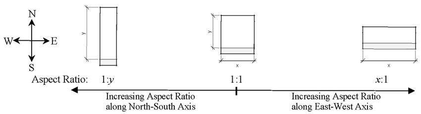
Aspectratiosareoftwotypesofhorizontalaspectratioand verticalaspectratio.Inourresearchpaper,weworkonthe horizontalaspectratio.Horizontalaspectratioistheratioof L/BwhichislengthL tothebaseB. Thehorizontal Aspect Ratioisalsocalledtheplanaspectratio. Fig 1.1.1 horizontal aspect ratio
1.2 OBJECTIVES
TodefinethebestsuitableAspectratiointallbuildings thatcanprovidesoundwindloading byobservingthe comparativestudies.

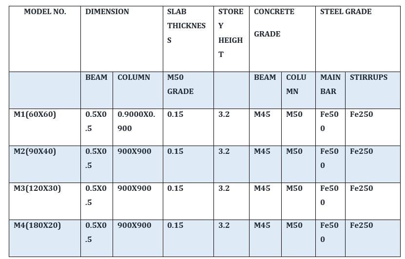
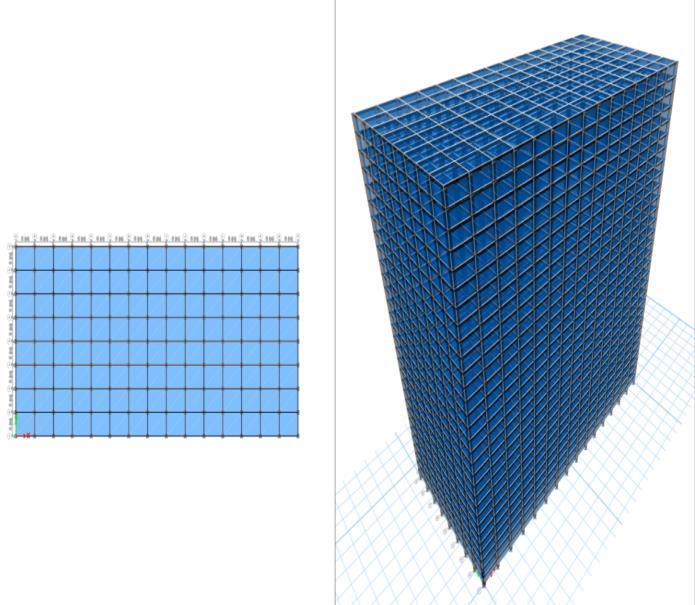
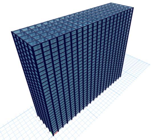
4. Structure Details Cross sectionofbeam0.5x0.5mforallmodels. Cross sectional dimension of column 0.9mx0.9 m for 60mx60m,90mx40m,120mx30m,180mx20m Slab thickness 0.15m NumberofstoreysG+30 Eachstoryheightis3.2m. Supports:Fixed.
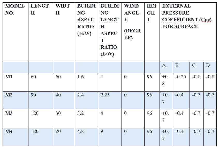
WindloadsforthebuildingaccordingtoIS875part3 havebeendonebyusingthevariousparameters Assigning of calculated wind loads on the modeled buildingsistobedone.
Afterthatourmodelisreadyforanalysisanddesign. Runtheanalysisandcheckthedesign. Checkresults.
International Research Journal of Engineering and Technology (IRJET) e ISSN: 2395 0056 Volume: 09 Issue: 01 | Jan 2022 www.irjet.net p ISSN: 2395 0072 © 2022, IRJET | Impact Factor value: 7.529 | ISO 9001:2008 Certified Journal | Page596 2 Literature Review Guleria, 1481 1485 (2014) The structural behavior of multi storybuildingsforvariousplanconfigurationssuchas rectangular,C,L,andI shapewasconcludedinhisresearch article. The ETABS software is used to model a 15 story R.C.C. framed building for study. Maximum shear forces, bendingmoments,andmaximumnarrativedisplacementare computedandcomparedforallofthestudiedscenariosonce the structure has been analyzed. The storey overturning momentvariesinverselywithstoreyheight,accordingtothe multi storybuilding'sinvestigation.Furthermore,L shape andI shapebuildingshavenearlyidenticalresponsestothe overturningmoment.Thedisplacementofstoriesgrewwith storey height up to the sixth storey, reaching a maximum value,andthenbegantodecrease.Modeformsarecreated viadynamicanalysis,anditmaybestatedthatasymmetrical plansgothroughthisprocess.
Themethodofanalysisofthetallbuildingofvariousaspect ratiosare: Wehavetodoextensiveliteraturesurveysbyreferring tobooks,technicalpapersorresearchpaperscarriedout tounderstandbasicconceptsofthetopic. Thenidentificationoftheneedforresearchisdone. Formulationofprocessinanalyticalworkwhichistobe carriedout. Thenallthedatacollectionisdone. ThenwepreparemodelsinETABS 30storybuildingisconsideredfortheanalysis.
Studies of resultsare done and then story drift,shear, storydisplacement,windintensityalltheaspectratioof model and determination of structurally efficient buildingistobedone.
AfterthatvariousAspectratioplansarepreparedforthe buildings. Afterthepreparationofmodelsalltheloads,deadload, liveload,andloadcombinationsareassigned.
3. Methodology
Afterallworksinterpretationofresultsandconclusion.
Muley, P. V, Senghani, J. M. & Radke, A. S. 2460–2464 (2019) Inthisstudy,theperformanceofhigh risebuildings under seismic and wind excitation for various plan configurations in the same area was reinforced. During seismicandwindexcitation,high risebuildingconstructions of various Plan configurations will behave. The general geometry,scale,andshapeoftallRCCbuildingswillaffect howtheybehave.FortheG+60storystructure,twenty one modelswerecreated,rangingfromaLy:Lxratioof1:1to 1:3.Thesearethoughttobeintheseismiczone IV.Finite Element Analysis is used to create and analyze all of the models, and the software ETABS 2017 is used to evaluate them.AsthePlanaspectratiogrowsintheYdirection,the displacement of the top storey increases. The building's stability,ontheotherhand,appearstoberisingastheLy:Lx ratiorises.Forhigh risebuildings,theplanaspectratioLy: Lxiscritical.Withincreasingaspectratios,theY direction storey drift parameter for top storey displacement is maximized Tirkey, N. & Ramesh Kumar, G. B. 514 518 (2020) The diagrid structure (diagonal perimeter, also known as the diagridstructure)hasemergedasaninnovativemethodin the recent construction field, Tall buildings and high rise structuresarebeingdevelopednotonlyintheengineering industry,butalsointhearchitecturalfield.,accordingtohis paper. In comparison to traditional buildings, it has also madetheconstructionstifferandlighter.ETABSsoftwareis usedtodesign,evaluate,andcomparethediagridstructure totheconventionalconstruction,withafocusonseismicand windanalysisparameters.Allstructuralpartsofthediagrid model are constructed according to IS 456:2000 and the Linear Static Method, and seismic load combinations are calculated using IS 1893 (PART 1): 2002. When the structure's height is increased, the lateral load resisting system outperforms the structural system in resisting gravityloads.Thelayoutandefficiencyofthediagridsystem havereducedthenumberofstructuralelements.
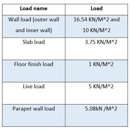
International Research Journal of Engineering and Technology (IRJET) e ISSN: 2395 0056 Volume: 09 Issue: 01 | Jan 2022 www.irjet.net p ISSN: 2395 0072 © 2022, IRJET | Impact Factor value: 7.529 | ISO 9001:2008 Certified Journal | Page597 ConcretegradeM45forbeamandforcolumnM50 SteelgradeFe500forlongitudinalbarsanddistribution bars. SteelgradeforstirrupsFe250 Table 4.0.1: structure details 5. Structural Load Calculation 5.1 Calculation of Dead Load as per IS 875 Part 1 and Live Load as per IS 875 Part 2 Calculation of wall load Table 1.11 Thicknessofwall=0.3m brickworkdensity=20kn/m^3(wetake1st classbrick) = Density of brick X thickness of wall X (Height of Wall Depth of Beam) + (plaster thickness X (Height of Wall DepthofBeam)Xdensityofplaster)=20X0.3X(3.2 0.70) +(0.027X2.6X22)=16.54KN/M^2 Forinnerwallwhosethicknessis0.2m=10KN/M^2 Slab load calculation Thicknessofslab=150mmor0.150m Densityofconcrete=25KN/M^3 =DensityofconcreteXthicknessofslab =25X0.150 =3.75KN/M^2 Floor Finish Load in Slab AsperIS:875part1(deadload)forfloorfinishloadistaken as For=1kN/m^2thicknessof50mm=0.05M,densityofcementmortar =20 =ThicknessKN/M^3offloorfinishXdensityofcementplaster =0.05X20 =1 So,KN/M^2thetotalloadinslab=3.75+1 =4.75KN/M^2 Live Load as per IS:875 part 2 1987 Live Load for commercial building as per IS code is = 5 KN/M^2Table1.12 Parapetwallload=1m =1X20X0.254=5.08kN/M^2 Table 5.0.1 load details
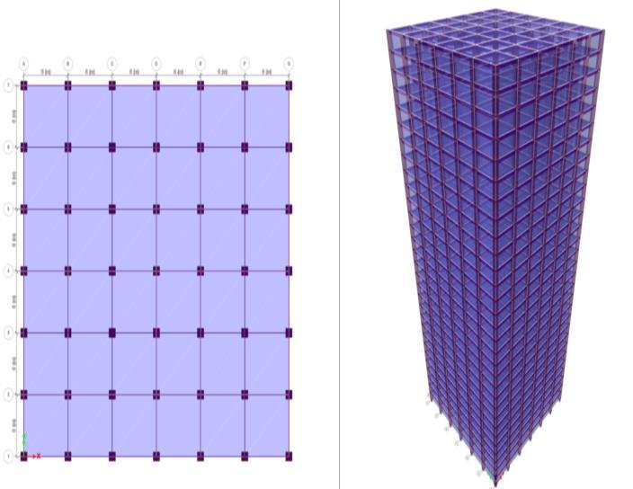
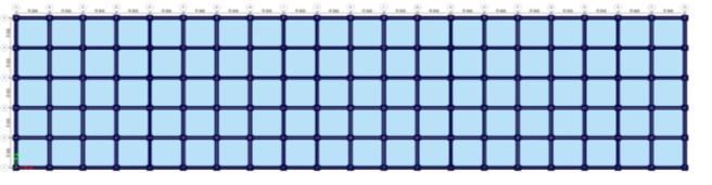
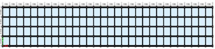
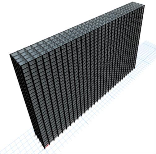
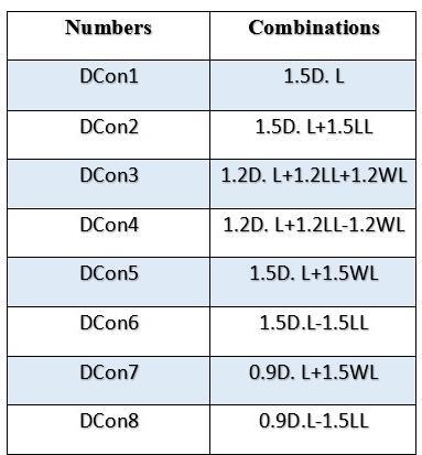
International Research Journal of Engineering and Technology (IRJET) e ISSN: 2395 0056 Volume: 09 Issue: 01 | Jan 2022 www.irjet.net p ISSN: 2395 0072 © 2022, IRJET | Impact Factor value: 7.529 | ISO 9001:2008 Certified Journal | Page598 6. StructureFigFigures6.0.1 Model m1 (60m x 60m) Fig 6.0.2 Model M2 (90m x 40m) Fig 6.0.3 model M3 (120m x 20m) Fig 6.0.4 model M4 (180m x 60m) 7. Load CombinationTable7.0.1Load Combinations Details 8. Wind Load Analysis As Per Is 875 Part 3 (2015) 8.1 Wind load calculation Windspeed(AsperIS 8752000Cl.6.3)
International Research Journal of Engineering and Technology (IRJET) e ISSN: 2395 0056 Volume: 09 Issue: 01 | Jan 2022 www.irjet.net p ISSN: 2395 0072 © 2022, IRJET | Impact Factor value: 7.529 | ISO 9001:2008 Certified Journal | Page599 Vz = Vb K1 K2 K3 K4 Vz designwindspeedinm/s(Clause5.3) Vb basicwindspeedinm/s(AppendixAClause5.2) K1 probabilityfactor(riskco efficient)Cl.6.3.1 K2 TerrainroughnessandheightfactorCl.6.3.1 K3 TopographyfactorCl.6.3.1 K4 ImportancefactorforthecyclonicregionCl.6.3.1 8.2 Design Parameter for wind load Vb =50(forVishakhapatnamregion) K1 =for50yearlifespanofbuilding=1 K2 = (Terrain1.15category)=3, Structureclass=C(forbuildingheightabove50m) K3 =1(whentheupwindslopeismorethan3thantheeffect oftopographyK3willbetakenas1) k4 =1 Table 8.01 Wind load Calculation 9. Results and Discussion When the aspect ratio of a building increases, the storey displacementalsoincreases.Thiswillshowhowmuchwind loadabuildingofaspecificationcanstandandtherefore,this gives an important point of consideration in designing a building that will be subjected to the heavy wind loads, especiallyintheareaswheretheeffectofwindloadismore prominent than the effect of an earthquake. This chapter dealswiththeconcludingremarksdrawnfromtheresultsof alltheanalysisanddesignmadefortheG+30storeybuilding withthedifferenttypeofaspectratiohavingsamefloorarea (3600sq.m)isconsideredforanalysis.Theresultshavebeen presentedintabularformalongwiththegraphicalmodein thischapter. Table 9.0.1 Results
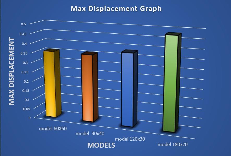
Fromtheresults,wecansaythatthedisplacementinmodel 180X20ismuchmorethaninanothermodelwithrespectto windloads.Theaxialforcesincolumnsincreaseastheaspect ratio increasesas well as the bending moment in columns also increase. The base reaction in the x direction is comparativelylessthanin they direction.Thesameeffect has been observed for beam, no major changes have been seen 9.1 Maximum displacement graph ThisgraphshowsaMaximumdisplacementoneachbuilding duetowindload.Resultsareshownasacomparisonofall the models Starting from plan aspect ratios of all the structures,analysiswithdifferentaspectratioslocatedina highwindzone.
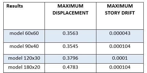
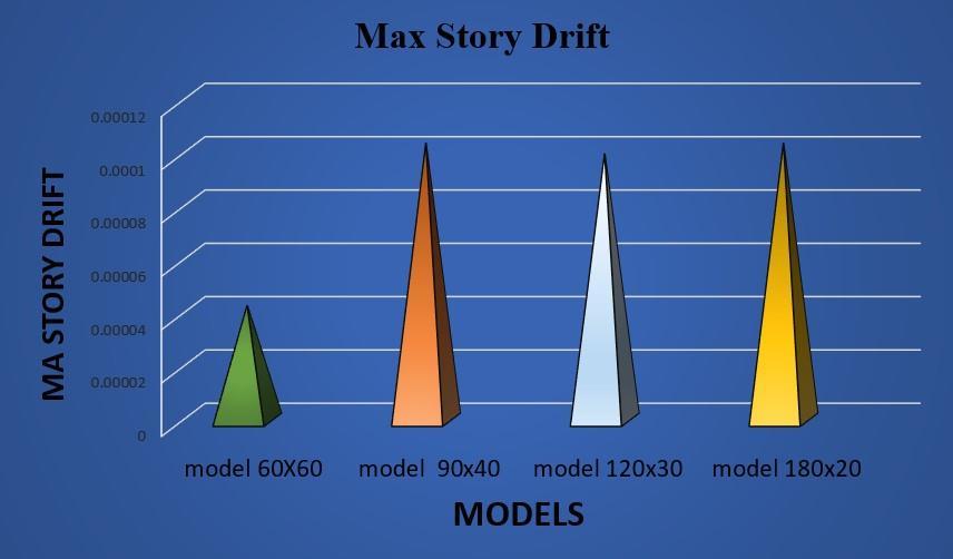
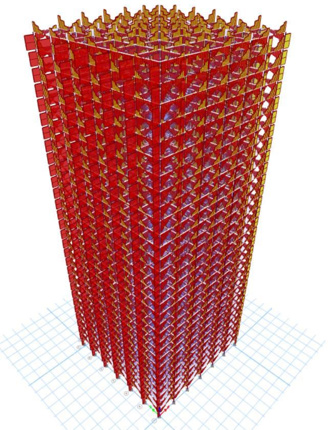
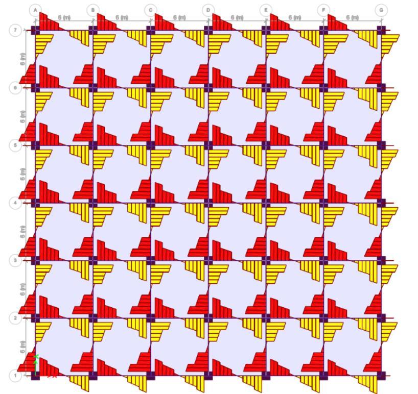
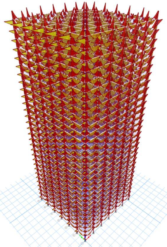
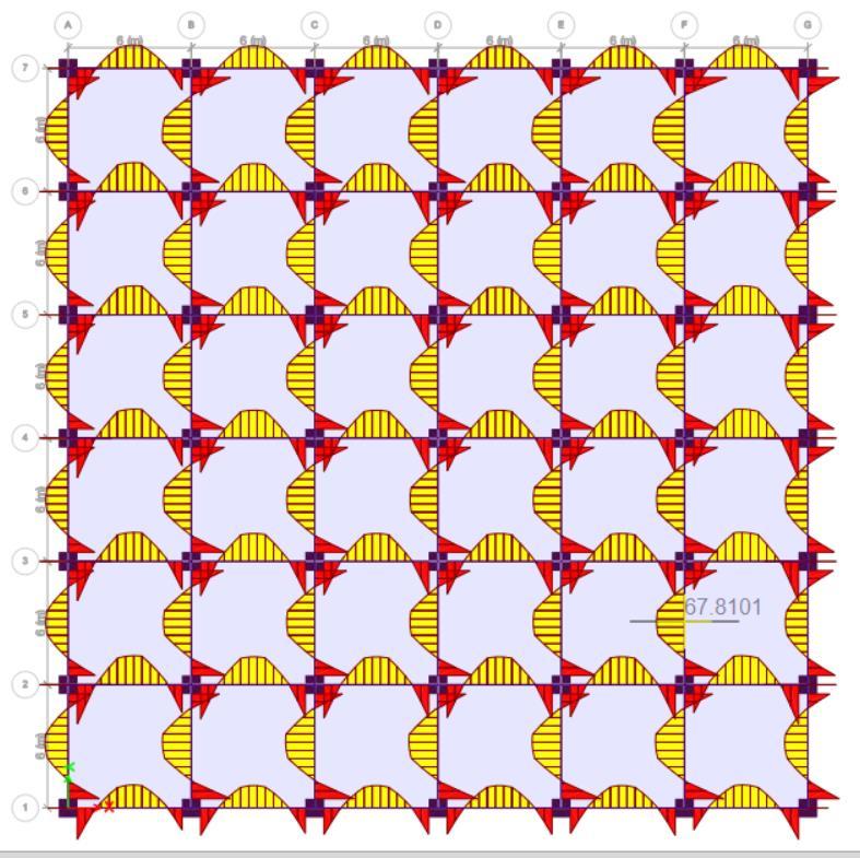
International Research Journal of Engineering and Technology (IRJET) e ISSN: 2395 0056 Volume: 09 Issue: 01 | Jan 2022 www.irjet.net p ISSN: 2395 0072 © 2022, IRJET | Impact Factor value: 7.529 | ISO 9001:2008 Certified Journal | Page600 Fig 9.0.1 Max Displacement 9.2 Maximum Story Drift Thisgraphshowsamaximumstorydriftoneachbuildingdue towindload.Resultsareshownas acomparisonofallthe modelsStartingfromplanaspectratiosofallthestructures, analysiswithdifferentaspectratioslocatedinahighwind zone Fig 9.0.2 Max Story Drift 10. Shear Force and Bending Moment Diagram of Model 60m X 60mFig 10.1 Shear Force (Elevation View) Fig 10.2 Shear Force (Plan View)
International Research Journal of Engineering and Technology (IRJET) e ISSN: 2395 0056 Volume: 09 Issue: 01 | Jan 2022 www.irjet.net p ISSN: 2395 0072 © 2022, IRJET | Impact Factor value: 7.529 | ISO 9001:2008 Certified Journal | Page601 Fig 10.3 Bending Moment (Elevation View) Fig 10.4 Bending Moment (Plan View) 11. Conclusions
Comparison of regular and irregular structures in terrain category was done on the basis of storey displacement, storeydrift,storeyshear.Followingconclusionpointswind analysisoftheG+30storybuildings.
5. Thestoreydisplacementisgreatestina buildingwith twospans(square)andlowestinabuildingwithtwenty spans(rectangular)
3. With an increase in the number of spans, the storey driftsgraduallydecreaseinthex direction.Thestorey driftissmallerforbuildingswith20spansandhigher forbuildingswithtwospans.
2. Thebaseshearisobtainedlowerfor2spansbuildings andhigherfor20spansbuildings.Thelowestvalueis obtainedinthecaseof2bay(square)buildingwhereas the highest is in the case of a 20 bay (rectangular) building.
1. It was discovered in this investigation that when the number of spans rises, the base shear increases gradually.
6. Thestoreydriftsiny directionincreasegraduallywith an increase in the number of spans since it is much narrowsidecomparativetothex direction.
4. Inx direction,thestorydisplacementdecreaseswithan increaseinthenumberofspans.
[3] Chen,F.Binetal.StudyofWindLoadsandWindSpeed AmplificationsonHigh RiseBuildingwithOpeningby NumericalSimulationandWindTunnelTest.Adv.Civ. Eng.2020,(2020).
[4] Ahmed, M., Ahmed, N. S., Roy, S. & Haque, M. A ComparativeStudyonVariousHorizontalAspectRatios onSeismicPerformanceofRegularShapeG+10Storey RCC Building. (2019) doi:10.13140/RG.2.2.24052.81284.
[2] Sanyal,P.&Dalui,S.K.Effectsofcourtyardandopening onarectangularplanshapedtallbuildingunderwind load.Int.J.Adv.Struct.Eng.10,169 188(2018).
[8] Rajas, A. S. & Shelke, N. L. Wind Analysis of High Rise BuildingwithDifferentBracingSystems.3,1923 1930 (2016).
[9] Sadh,A.&Pal,A.ALiteratureStudyofWindAnalysison HighRiseBuilding.Int.J.Adv.Eng.Res.Sci.5,263 265 (2018).
[10] Sadh,S.K.&Pendharkar,U.InfluenceofAspectRatio& Plan Configurations on Seismic Performance of MultistoreyedRegularR.C.C.Buildings:AnEvaluationby Response Spectrum Analysis. Int. Res. J. Eng. Technol. (2016).
[5] Guleria, A. Structural Analysis of a Multi Storeyed BuildingusingETABSfordifferentPlanConfigurations. Int.J.Eng.Res.Technol.3,1481 1485(2014).
[7] Tirkey,N.&RameshKumar,G.B.Analysisonthediagrid structure with the conventional building frame using ETABS.Mater.TodayProc.22,514 518(2020).
International Research Journal of Engineering and Technology (IRJET) e ISSN: 2395 0056 Volume: 09 Issue: 01 | Jan 2022 www.irjet.net p ISSN: 2395 0072 © 2022, IRJET | Impact Factor value: 7.529 | ISO 9001:2008 Certified Journal | Page602 7. Ithasbeenobservedthatthestoreydisplacementiny directionincreaseswiththeincreaseofspans. 12. REFERENCES
[6] Muley,P.V,Senghani,J.M.&Radke,A.S.Performanceof HighRiseBuildingUnderSeismicandWindExcitation for the Different Plan Configurations of Same Area. 2460 2464(2019).
[1] Paul,R.&Dalui,S.K.Windeffectson‘Z’plan shapedtall building:acasestudy.Int.J.Adv.Struct.Eng.8,319 335 (2016).