8
IX
https://doi.org/10.22214/ijraset.2020.31737
September 2020
International Journal for Research in Applied Science & Engineering Technology (IJRASET) ISSN: 2321-9653; IC Value: 45.98; SJ Impact Factor: 7.429 Volume 8 Issue IX Sep 2020- Available at www.ijraset.com
Analysis and Design of G+6 Residential Building using STAAD PRO Mr. M. Durga Rao1, Ch. Pavan Sai2, K. Ravi Teja3, K. K Nagendram4, B. Ram Jaswanth5 1
Assistant Professor, Gudlavalleru Engineering College, Gudlavalleru, India 2, 3, 4, 5 Student, Gudlavalleru Engineering College, Gudlavalleru, India
Abstract: Analysis of a structure deals with the determination of behaviour of structures in order to predict the responses of real structures such as buildings, bridges, trusses etc. Under the influences of expected loading and external loading during the service life of a structure. The results of the analysis are then used for structural health monitoring. Computer software are also used for the calculation of forces, bending moments for a complex structural system. The principle objective of this study is the analysis and design of G+ 6 residential building using STAAD PRO software Keywords: structural health monitoring, calculation of forces and bending moment, STAAD PRO I. INTRODUCTION The world’s urban population is growing at very faster rate. Currently, about half of the world’s population is living in urban areas. In the coming decades, urban dwellers will make up roughly 60 to 70 percent of the world’s population. Though the urban population is growing at an alarming rate, the land available for construction is limited. Increasing population coupled with urbanization has made the construction of multi-storey buildings a necessity to house the millions. Housing the millions is possible only by constructing multi-storey buildings. As the height of building increases, the behavior of the structure becomes more complex, these are more sensitive to wind and earthquake loads and hence, we need to be very careful to design them. Reinforced concrete is the best suited for multi-storey buildings. It has occupied a special place in the modern construction due to its several advantages. Owing to its flexibility in form and superiority in performance, it has replaced the earlier materials like stone, timber and steel. It has helped the engineers and architects to build pleasing structures. However, its role in several straight line structural forms like, multi-storey building and bridges etc. is enormous. II. 1) 2) 3) 4) 5) 6)
METHODOLOGY
Step 1 - Collection of data Step 2- Planning and drawing in AUTOCAD Step 3 – Manual analysis of structure Step 4 – Design of concrete members Step 5 – Analysis in STAAD PRO Step 6 – Conclusion
III. SOFTWARE USED A. STAAD PRO It allows structural engineers to analyze and design virtually any type of structure through its flexible modeling environment, advanced features and fluent data collaboration. The main advantages are advanced automatic load generation facilities for wind , moving loads. Isomeric and perspective views with 3D shapes, joints, members or elements can be obtained. B. Autocad Computer aided design which are computer based tools used to assist designers, engineers, architects in their design activities. CAD is used as preparing architectural drawings and interior design and modeling.
©IJRASET: All Rights are Reserved
1226
International Journal for Research in Applied Science & Engineering Technology (IJRASET) ISSN: 2321-9653; IC Value: 45.98; SJ Impact Factor: 7.429 Volume 8 Issue IX Sep 2020- Available at www.ijraset.com IV.
BASIC DATA AND FLOOR PLAN
Floor plan Total height of building = 22.4m Height of each floor = 3.2m Plot area = 648 sq.m No of flats (per floor) = 4 Total no of flats = 24 Number of columns = 30 Numbers of beams (per floor) = 68 V. MANUAL ANALYSIS BY KANI’S METHOD Kani’s Method was developed by Dr. Gasper Kani of Germany in 1947. The method is named after him. This is an indirect extension of slope deflection method .this is an efficient method due to simplicity of moment distribution. This method offers an iterative scheme for applying slope deflection method. It is also known as Rotation Contribution Method. This is a good iterative procedure avoiding the mistakes during the execution of the process error is self-eliminative. All this effort can be cut short very considerably by using this method. Frame analysis is carried out by solving the slope-deflection equations by successive approximations Useful in case of side sway as well. Operation is easy, as it is carried out in a specific direction. If some error is occurred it will be eliminated in subsequent cycles if the restraining moments and distribution factors have been determined correctly. That is why in this project Kani's method is used for the analysis of structure for gravity loads.
Frame in X - Direction
©IJRASET: All Rights are Reserved
1227
International Journal for Research in Applied Science & Engineering Technology (IJRASET) ISSN: 2321-9653; IC Value: 45.98; SJ Impact Factor: 7.429 Volume 8 Issue IX Sep 2020- Available at www.ijraset.com Final Moments HORIZONTAL MEMBERS FINAL MOMENTS
END MOMENTS VALUES
Mab
-64.56
Mba
88.17
Mbc
-35.35
Mcb
4.57
Mde
-118.03
Med
134.23
Mef
-34.4
Mfe
6.38
Mgh
-117.83
Mhg
133.55
Mhi
-36.7
Mih
4.87
Mjk
-117.79
Mkj
133.84
Mkl
-35.85
Mlk
5.49
Mmn
-117.7
Mnm
133.78
Mno
-36.03
Mon
5.55
Mpq
-118.04
Mqp
134.099
Mqr
-34.79
Mrq
6.02
Mst
-115.2
Mts
133.08
Mtu
-41.27
Mut
2.9
©IJRASET: All Rights are Reserved
VERTICAL MOMENTS FINAL END MOMENTS VALUES MOMENTS Mad 61.89 Mda 56 Mbe -53.51 Meb -51.98 Mcf -5.82 Mfc -6.58 Mdg 53.64 Mgd 54.31 Meh -48.62 Mhe -49.59 Mfi -4.71 Mif -4.94 Mgj 54.97 Mjg 54.84 Mhk -50.2 Mkh -49.84 Mil -4.93 Mli -4.81 Mjm 54.64 Mmj 54.71 Mkn -49.86 Mnk -50 Mlo -4.83 Mol -4.73 Mmp 54.29 Mpm 53.63 Mnq -49.6 Mqn -48.88 Mor -4.75 Mro -4.84 Mps 56.74 Msp 60.99 Mqt -51.92 Mtq -55.2 Mru -5.34 Mur -9.95 Msv 45.35 Mtw -37.17 Mvx -1.92
1228
International Journal for Research in Applied Science & Engineering Technology (IJRASET) ISSN: 2321-9653; IC Value: 45.98; SJ Impact Factor: 7.429 Volume 8 Issue IX Sep 2020- Available at www.ijraset.com VI.
STOREY NO 6 5 4 3 2 1 GF
hi 22.4 19.2 16 12.8 9.6 6.4 3.2
BASE SHEAR CALCULATIONS
CALCULCULATIONS OF BASE SHEAR SIESMIC WEIGHT wihi^2 k=wihi^2/sum of(wi*hi^2) 4430 2222796 0.225 8200 3022848 0.306 8200 2099200 0.212 8200 1343488 0.136 8200 755712 0.076 8200 335872 0.034 8200 83968 0.008 TOTAL BASE SHEAR
Qi=Vb*k 461.2 656.43 454.78 291.74 163.03 72.93 17.16 2117.27
VII. STAAD PRO ANALYSIS In our project we considered a G+6 residential building for planning design and analysis. The each floor consists of 4 no’s of flats and we analysis total structure in STAAD PRO.
Loads Applied On Structure Dead load
©IJRASET: All Rights are Reserved
Live load
1229
International Journal for Research in Applied Science & Engineering Technology (IJRASET) ISSN: 2321-9653; IC Value: 45.98; SJ Impact Factor: 7.429 Volume 8 Issue IX Sep 2020- Available at www.ijraset.com A. Bending Moment from STAAD PRO
B. Design from STAAD PRO Beam
©IJRASET: All Rights are Reserved
Column
1230
International Journal for Research in Applied Science & Engineering Technology (IJRASET) ISSN: 2321-9653; IC Value: 45.98; SJ Impact Factor: 7.429 Volume 8 Issue IX Sep 2020- Available at www.ijraset.com VIII.
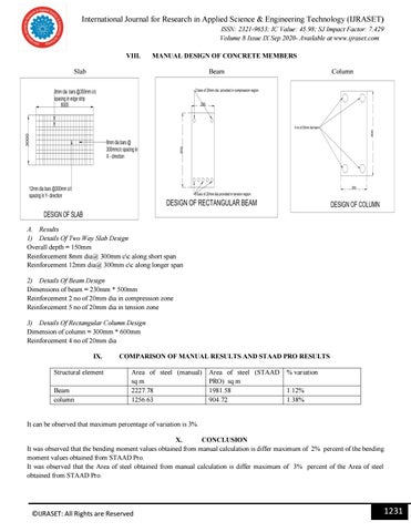
MANUAL DESIGN OF CONCRETE MEMBERS
Slab
Beam
Column
A. Results 1) Details Of Two Way Slab Design Overall depth = 150mm Reinforcement 8mm dia@ 300mm c\c along short span Reinforcement 12mm dia@ 300mm c\c along longer span 2) Details Of Beam Design Dimensions of beam = 230mm * 500mm Reinforcement 2 no of 20mm dia in compression zone Reinforcement 5 no of 20mm dia in tension zone 3) Details Of Rectangular Column Design Dimension of column = 300mm * 600mm Reinforcement 4 no of 20mm dia IX. Structural element Beam column
COMPARISON OF MANUAL RESULTS AND STAAD PRO RESULTS Area of steel (manual) sq.m 2227.78 1256.63
Area of steel (STAAD PRO) sq.m 1981.58 904.72
% variation 1.12% 1.38%
It can be observed that maximum percentage of variation is 3%. X. CONCLUSION It was observed that the bending moment values obtained from manual calculation is differ maximum of 2% percent of the bending moment values obtained from STAAD Pro. It was observed that the Area of steel obtained from manual calculation is differ maximum of 3% percent of the Area of steel obtained from STAAD Pro.
©IJRASET: All Rights are Reserved
1231
International Journal for Research in Applied Science & Engineering Technology (IJRASET) ISSN: 2321-9653; IC Value: 45.98; SJ Impact Factor: 7.429 Volume 8 Issue IX Sep 2020- Available at www.ijraset.com REFERENCES [1] [2] [3] [4] [5] [6] [7]
Building Planning And Drawing By Dr. N. Kumara Swamy. Reinforced Concrete Design By N. Krishna Raju And R.N. Pranesh. Earthquake Resistant Design Of Structures By S.K. Duggal. Analysis And Design Of Multistored Residential Building Using STAAD PRO By Sk Salman And V Raj Kumar. Analysis And Design Of Residential Building By Prof Shaikh Ibrahim. Analysis And Design Of G+6 Residential Building Using STAAD PRO” By Prof S. Sudheer. Indian standard code books.
©IJRASET: All Rights are Reserved
1232