Troubleshooting
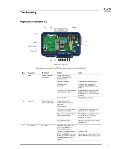
Diagnostic LEDs description in.yj D5
D4
Power
FLO
D2*
KIN
D7
D8, D9 & D10 Power Ext
D3
D6 Diagnostic LEDs (x13)
* D2 designation is not visible on the PCB, D2 is situated between component RD2 and E2.
Case 1
2
3
Designation
Description
Details
Power
General 12V power supply status
Should always be ON If OFF, nothing will work. Possible causes:
Power Ext
D8, D9 & D10
External 12V and 5V power supplies status
MCU status
Action
Input not connected
Check the input connection on P12
Installation main breaker OFF
Check the main breaker of the installation. Go to GFCI/RDC Trips section.
Short on one connector between 12V line and near signal
Check following connectors in order: P22 (C-pin 6); P17 (CO-pin 6); P38 (RGB-pin 4), P33 (LIGHT-pin 3), P1 (pin 6)
Issue on board
Change the in.yj-V3 board
Should always be ON If OFF, external accessories won't work. Possible causes: Short on one connector between 12V line and near signal
Check following connectors in order: P22 (C-pin 6); P17 (CO-pin6)
Short on one connector between 5V line and near signal
Check following connectors in order: P22 (C-pin 4); P17 (CO-pin 4); P1 (pin 4); P8 (Pin 1)
Keypad disconnected
Check the keypad connection on P22 connector (C2).
D8 should always blink, D9 and D10 are always OFF. If not, possible causes: The board is starting (power on)
Wait about 10s
D8, D9 and D10 flashing in sync: bootloader present, but there is no valid firmware in the MCU memory
Power down the in.yj, insert an in.stik with a valid software and reapply power
3