Door Systems Technical Guide
2
About Reveal or conceal your cabinetry with Furnware Group’s range of stylish and functional door systems from internationally renowned brands Rivvi and Salice. The collection boasts a number of varied door systems, each with its own unique functionality that allows you to create a specific look for your cabinetry such as pocket doors, flap doors, bi-fold doors and sliding doors. These door systems are designed to be used throughout kitchen, laundry and office fit outs and include the latest European technology to suit modern styles. So, if you are looking for a stylish and functional way to differentiate your cabinet doors form your competitors, look no further than Furnware’s door system offering. We are the door system specialists offering expert advice cultivated over 35 years’ experience in selling cabinet door hardware.
Contents Pocket Door Systems Salice Gravity
7
Salice Exedra2 Star
10
Salice Exedra2 Smart
14
Coplanar Systems Salice S10
18
Salice M50 Flex
23
Folding Door Systems Salice Folder 90 - 180
30
Rivvi Bi-Fold
35
Sliding Systems Rivvi Wardrobe System
42
Rivvi 40kg System
53
Rivvi Light Duty Sliding Door System
55
Rivvi Top Hung Door
56
Rivvi Barn Door
57
Flap Door Systems Salice Wind
59
Salice Pacta
73
Door Weight Calculation Table
86
3
Pocket Door System
4
Furnware Group System Fully customised installation instructions Simple assembly of components Our unique configuration software allows for customisation on every order to ensure that your installation is as fast and as hassle free as possible! Follow these 4 easy steps:
1. Send us your dimensions: • Door Size (width x height) • Cabinet depth. • Or use our configurator (Page 7)
2. We specify the unique components that you require for the installation.
3. We send you the customised cutting and installation instructions. (dxf files also available)
4. Follow the step by step guide to complete your pocket door installation.
Contact Furnware Group on 1300 222 600 for all orders and enquiries!
Exedra Gravity suits all types of furniture and can be applied to a wide range of dimensions: • • • •
Door height from 1100mm to 3000mm Doors width from 300mm to 900mm Doors thickness from 16mm to 30mm Door weight up to 40kg
Fully compatible with Exedra2 Smart (page 14) for 3 door installations.
Note: standard door projection when fully retracted is 107mm. Some configurations may cause this projection to increase. Please confirm door projection when ordering.
5
Gravity
6
Exedra Gravity
OUT
IN
Movements developed for maximum ease of use Two options available: OUT – Doors open independently from within the cabinet with assisted motion, activated by a light touch. IN – The doors retract with a smooth, perfectly balanced motion in response to a gentle push. Exedra Gravity can be supplied with hinges and Smove, for a decelerated closing, or Push to open hinges for handle-less doors. Configure your system’s movement with the online configurator.
Use the QR Code to access the online configurator The Configurator works for both Exedra Gravity, Star and Smart 7
Simple, reliable, practical The concealed sliding mechanism, contained within a 55mm housing, allows for easy adjustment and access without disassembling the cabinet. It attaches directly to the cabinet side in just a few simple steps. Exedra Gravity’s innovative technology operates without the need for cables, tie rods, or springs. Fluid and smooth motion assisted by magnetic dampers designed to control the speed. The online configurator allows better customisation for every version of the system. (QR on page 7)
1
1a
Exedra Gravity OUT:
5
Exedra Gravity IN:
6
automatic door extraction movement with counterweight.
4
3
8
Magnetic buffer for soft insertion.
3
Load-bearing door profile.
4
Sliding carriage profiles.
5
Quick coupling hinges.
6
All door adjustments are accessible from the front of the cabinet.
2 4
6
1a
1
automatic door insertion movement with counterweight.
2
5
2
4
3
4
Exedra Gravity - Customised Fully assembled solution according to customer requirements.
The Exedra Gravity system is produced according to the dimensional specifications provided by the customer. The customer only has to assemble the system on the cabinet with the provided drilling patterns. The locating clips and positioning stops ensure a fast and secure assembly and removal from the cabinet.
How to order a customised Exedra Gravity system
To order a customised Exedra Gravity system, go to the Salice web configurator: www.configurator.salice.com. To purchase your configured system, please contact your local Salice dealer. How to order Our unique configuration software allows for customisation on every order to ensure that your installation is as fast and as hassle free as possible! Follow these four easy steps:
1. Send us your dimensions: • Door Size (width x height) • Cabinet depth. • Or use our configurator (Page 7)
2. We specify the unique components that you require for the installation.
3. We send you the customised cutting and installation instructions. (dxf files also available)
4. Follow the step by step guide to complete your pocket door installation.
9
10
Salice Exedra2 Star
Salice Exedra2 enables the opening or closing of a pair of linked doors simultaneously with a single action and is able to be used as a single unit or a double unit pair. Exedra2 Star completely conceals the door panels behind the cover panel whether the doors are open or closed. With completely free unobstructed access available for widths up to 2985mm, the Exedra2 Star is the perfect choice for elegant concealment of wardrobes, kitchens, pantries, office areas, butlers’ pantries and a host of other applications. An additional design feature of the Exedra2 Star is the ability to have the inner door panels (TL2) up to 90mm wider than the outer door panels (TL1) which allows the maximum unobstructed opening size to be extended to 3165mm. Fluid and controlled: eliminating the need for cables, tie rods, or springs, the Exedra2 technology uses the force of gravity, along with the magnetic dampers that control the doors, offering a fluid, silent and long-lasting movement, tested up to 50,000 cycles.
Design Considerations Required internal pocket width = 180mm Required door panel gaps = 3mm Minimum thickness of side panel (SPI) = 18mm Door height = 1800mm – 3000mm Door thickness = 18mm Maximum door panel weight = 25kg Minimum Sizes Minimum door panel width = 450mm (TL1, TL2) Minimum overall opening width (including pockets) = 2217mm* (LT) Minimum depth of pocket required (at minimum door width) = 730mm (LPU) Maximum Sizes Maximum door panel width = 750mm (TL1, TL2) Maximum overall opening width (including pockets) = 3417mm* (LT) Minimum depth of pocket required (at maximum door width) = 1030mm (LPU) *When 2 systems are used as a double pair
Height: min1800 1800mm mm-- max max 3000mm Height: min 2600 mm
Exedra2 Star
Width: min 450 m mmax 750 mm
Maximum
weight 50
Kg
Exedra2 Smart
mm - max 2600 mm
How to order Exedra2 Star Get in touch with your Furnware Group representative and provide details of your available space to confirm the appropriate door system design, pricing, and current lead times.
11
Salice Exedra2 Star
1
1
2
3
2
1
Unique patented door opening system. The exterior surfaces of the doors are always protected during the opening and closing cycles.
2
Non load-bearing track on the top of the cabinet.
3
Magnetic buffer for assisted cushioned doors insertion
4
Structural aluminium frame for doors movement.
5
Frontal insertion of the load-bearing frame facilitating its installation in a wall recess.
6
Side frame to support the lower load-bearing track. All of the load is carried by the side panel. The track does not require ground support.
7
Anti-crush device.
4
3
4
Adjustment: • vertical adjustment ± 5 mm • horizontal adjustment ± 3.5 mm Front adjustment: • upper ± 3 mm • lower ± 2 mm
7
The Exedra2 system is the ideal mechanism in a host of applications. The absence of a frontal lower track makes it adaptable to any application, from traditional cabinets to walk-in wardrobes. The system does not necessarily have to be placed on the floor, therefore it is possible to create systems raised from the ground or placed on a cupboard or a chest of drawers.
5
6
Thanks to the innovative door movement system with its moving load-bearing frame, the weight of the system and the doors is carried solely by the side of the cabinet; the system places no load on the top of the cabinet. As a result, double systems with an 5of more than 3000 mm are possible without requiring 6 enormous free internal spans a central panel or support.
Exedra2 Star Traditional
In wall recess
Raised from the ground
In wall recess
Raised from the ground
Exedra2 Smart
12
Traditional
Salice Exedra2 Star
50
35
Min 60mm 23
Min 30
Min 25
Min 20 LT SPI
SPF 180
SPI
LI
180 SPF
LPU = TL1 + 280
D
D 3
KEY:
Handle location
TL_1
3
TL_2 3
TL_2 3
TL_1 3 Handle location
LT = External size SPI = Side panel internal LI = Internal size SPF = Side panel external TL1 = Outer door panel D = Pocket cover panel external overlay TL2 = Inner door panel LPU = Minimum pocket depth Q = Pocket cover panel
Enhance your Exedra 2 Star with a motorised upgrade, available by special order. Please allow a lead time of approximately 14 weeks. For enquiries, contact Furnware Group on 1300 222 600 for more information or to order. 13
14
Salice Exedra2 Smart
Salice Exedra2 enables the opening or closing of a pair of linked doors simultaneously with a single action and is able to be used as a single unit or a double unit pair.
Height: min 1800 mm - max 2600 mm
Height: min 1800 mm - max 2600 mm
Exedra2 Smart allows for shorter pocket depths. The door edges remain visible and protrude slightly when Exedra2 Star retracted into the pocket. Recessed handles or lip pull handles Exedra2 Starshould be used on Exedra2 Smart applications. Exedra2 Smart is able to be used as a single unit, paired in conjunction with single Exedra door, or as a double unit pair. Exedra2 Smart, allows door panel sizes to be consistent and equal across the installation. With free unobstructed access available for widths up to 2977mm the Exedra2 Smart is the perfect choice for elegant concealment of wardrobes, kitchens, pantries, office areas, butlers’ pantries, and a host of other applications. Fluid and controlled: eliminating the need for cables, tie rods, or springs, the Exedra2 technology uses the force of gravity, along with the magnetic dampers that Width: control the fluid, and long-lasting mindoors, 450 mm offering aM aximusilent m weight m 750 mm up to 50,000 cycles. 50 Kg movement,axtested Width: min 450 m mmax 750 mm
Maximum
Exedra2 Smart
weight 50
Kg
Design Considerations Required internal pocket width = 180mm Required door panel gaps = 3mm Minimum thickness of side panel (SPI) = 18mm Door height = 1800mm – 2600mm Door thickness = 18mm – 25mm Maximum door panel weight = 25kg Minimum Sizes Minimum door panel width = 550mm (TL1, TL2) Minimum overall opening width (including pockets) = 2209mm* (LT) Minimum depth of pocket required (at minimum door width) = 730mm (LPU) Minimum door protrusion when fully retracted = 95mm Maximum Sizes Maximum door panel width = 850mm (TL1, TL2) Maximum overall opening width (including pockets) = 3412mm* (LT) Minimum depth of pocket required (at maximum door width) = 930mm (LPU) *When 2 systems are used as a double pair
Compatible with Exedra Gravity for 3 door installations.
Height:min min1800 1800 mm mm - max Height: max3000mm 2600 mm
Height: min 1800 mm - max 2600 mm
Exedra2 Smart
Width: min 550 m mmax 850 mm Width: min 550 m mmax 850 mm
Maximum Maximum
weight 50
weight 50
Kg
Kg
How to order Exedra2 Smart Get in touch with your Furnware Group representative and provide details of your available space to confirm the appropriate door system design, pricing, and current lead times.
15
Salice Exedra2 Smart
1
2
3 Exedra2 Star Traditional
In wall recess
4
1
Unique patented door opening system. The exterior surfaces of the doors are always protected during the opening and closing cycles.
2
Non load-bearing track on the top of the cabinet.
3
Magnetic buffer for assisted cushioned doors insertion
4
Structural aluminium frame for doors movement.
5
Frontal insertion of the load-bearing frame facilitating its installation in a wall recess.
6
Side frame to support the lower load-bearing track. All of the load is Raised from ground carried by the side panel. The track does notthe require ground support.
Adjustment: • vertical adjustment ± 5 mm • horizontal adjustment ± 3.5 mm Front adjustment: • upper ± 3 mm • lower ± 2 mm
The Exedra2 system is the ideal mechanism in a host of applications. The absence of a frontal lower track makes it adaptable to any application, from traditional cabinets to walk-in wardrobes. The system does not necessarily have to be placed on the floor, therefore it is possible to create systems raised from the ground or placed on a cupboard or a chest of drawers.
6
5
6
Thanks to the innovative door movement system with its moving load-bearing frame, the weight of the system and the doors is carried solely by the side of the cabinet; the system places no load on the top of the cabinet. As a result, double systems with an enormous free internal spans of more than 3000 mm are possible without requiring a central panel or support.
Exedra2 Smart
Traditional
In wall recess
Raised from the ground
9
16
Salice Exedra2 Smart
50
35
Min 60mm 23
Min 30
Min 25
Min 20
LT SPF 180
SPI
SPI
LI
180 SPF
LPU = TL1 - D + 95
D
D TL_1
recessed handle location
3
TL_2
3
TL_2
3
TL_1 recessed handle location
KEY: LT = External size SPI = Side panel internal LI = Internal size SPF = Side panel external TL1 = Outer door panel
76.5+D
D = Outer door panel external overlay TL2 = Inner door panel LPU = Minimum pocket depth
Enhance your Exedra 2 Smart with a motorised upgrade, available by special order. Please allow a lead time of approximately 14 weeks. For enquiries, contact Furnware Group on 1300 222 600 for more information or to order. 17
Slider S10 Slider S10 is a coplanar system for kitchen cabinets and small wall cabinets with doors weighing up to 10 kg. Equipped with carriages with double horizontal rollers and connection-free runners that guarantee smoother and quieter movement than ever before. S10 is flexible: the Flex version can be adapted to any width of cabinet by simply cutting the profiles to measure. Due to its features, S10 is ideal for small units used in the kitchen and bathroom or for larger furniture intended for the living room, bedroom and offices.
18
Slider S10 Installation Dimensions Technical Information Coplanar two-door cushioned sliding system. Capacity 10 kg per door. Individual door properties: • Max. weight per door 10 kg (evenly distributed) • Width: - min. 450 mm - max. 1200 mm • Height: - max. 800 mm • Thickness: - min. 16 mm - max. 30 mm - max. with handle 40 mm
Material: a) wood or derived material b) glass with metal frame Door adjustment: • vertical adjustment ± 5 mm • horizontal adjustment ± 2.5 mm
Height from the ground: - 35 mm (kitchen cabinet)
Kitchen cabinet - upper ± 2,5 mm - lower ± 2 mm
Door front adjustment: • wall cabinet - upper ± 2 mm - lower ± 2,5 mm
Key Features: • Extremely easy to customise and assemble. • Secured with screws without the need of drilling or machining the doors and unit. • Single-piece sliding track. • Innovative suspended slider with double horizontal wheels. • Assisted opening and closing. • Front adjustment of the doors. › Wall unit with innovative door runner system. • Extreme strength and durability, stress-tested with 100,000 cycles. 19
Slider S10 Installation Dimensions
Wall Cabinet:
20
Slider S10 Installation Dimensions Kitchen Cabinet:
21
Slider S10 Installation Dimensions Slider S10 is a flexible system that can be adapted to the internal width of the unit (LI) with a minimum of 860 mm to a maximum of 2400 mm.
The handle must be positioned at a minimum of 10 mm from the edge of the door (at the centre of the unit) and a maximum of one third of its width (TL).
The maximum permitted superimposition (D) is 25 mm.
The cabinet has to be constructed so that the bottom panel of the kitchen cabinet, or the top panel of the wall cabinet is sufficiently rigid to prevent it from bending. For this reason, some reinforcement is always recommended.
22
M50 FLEX COPLANAR
23
Salice M50 Flex Coplanar Door Sets
M50 Flex is a two-door coplanar cushioned sliding system with customisable track length, ideal for wardrobes and storage cabinets in homes, offices and shops. • Made in Italy • Very easy to assemble and adjust with customisable track length • Super-smooth cushioned opening and closing with magnetic damping technology • High reliability, tested to 100,000 cycles. • Kit contains 1 x carriage kit, and 1 x profile kit (for double door installation) Door dimensions: • Max weight for each door 50 kg (evenly distributed). • Width: min 800 mm - max 1600 mm. • Height: max 2700 mm. • Thickness: min 18 mm - max with handle 40 mm. • Systems available to suit internal cabinet sizes from 1531mm to 3200mm
Cabinet Size
24
Part No. SAL.CPM50F.1930
Internal Cabinet Size 1531 - 1930mm
SAL.CPM50F.2330
1931 - 2330mm
SAL.CPM50F.2730
2331 - 2730mm
SAL.CPM50F.3200
2731 - 3200mm
Salice M50 Flex Coplanar Design Considerations
Coplanar two-door cushioned sliding system with customisable track length • - capacity 50 kg per door. Door dimensions: • Maximum weight for each door 50 kg (evenly distributed). • Width: - minimum 800 mm; - maximum 1600 mm. • Height: - maximum 2700 mm. • Thickness: - minimum 18 mm; - maximum with handle 40 mm. • Height from the ground: - 33 mm. Door adjustment: • Vertical ± 5 mm • Horizontal ± 3,5 mm • Front: - Upper ± 3 mm - Lower ± 3 mm
25
Salice M50 Flex Coplanar
Space Required
Door Overlap
26
Salice M50 Flex Coplanar Installation Dimensions
Slider M50 Flex is a flexible system that can be adapted to the internal width of the unit (LI) with a minimum of 1531 mm to a maximum of 3200 mm.
LI
The handle should be placed close to the leading edge of the door, or at a maximum distance of one third of its width (TL).
TL
The minimum permitted overlap (D) is 14 mm; maximum 25 mm.
D
D
27
Salice M50 Flex Coplanar Installation Dimensions
Depending on the internal width of the unit (LI), the mechanism is put together using a carriage kit and a profile kit which are supplied according to the part numbers in the table below.
LI (mm) Part Number
1531 ÷ 1930 SAL.CPM50F.1930
1931 ÷ 2330
2731 ÷ 3200
•
SAL.CPM50F.2330
•
SAL.CPM50F.2730
•
SAL.CPM50F.3200
•
LI
28
2331 ÷ 2730
Salice Folder 90 - 180 Folder is a concertina door system, created by combining hinged and sliding doors. It is available with two opening angles.
Folder
Folder is a concertina door system, created by combining hinged and sliding doors. It is available with two opening angles. Folder 90, for compartments up to 1200 mm. Allows 90° overlapping of doors. It is ideal for furniture placed where a 90° opening is required. Folder 90, for compartments up to 1200 mm. Allows 90° overlapping of doors. It is ideal for furniture placed where a 90° opening is required.
Folder 180 for compartments up to 1500 mm wide. Allows the doors a maximum opening of 180°, giving Folder 180 access for compartments up toof 1500 wide. Allows the doors a maximum opening of 180°, giving unrestricted unrestricted to the interior the mm cabinet. access to the interior of the cabinet.
• Folder 180 •
• Folder 90 •
29
• Folder • 3
Salice Folder 90 - 180 Comfort With a gentle pull of the hand, a smooth and silent opening and closing movement is achieved, thanks to assisted control.
Folder 180 when opening, the door is accompanied up to mid-way. A spring system then takes over, bringing the doors to full opening. The utilisation of a damper ensures that the door gently reaches the maximum opening. Similarly, closing involves the use of a hand to bring the door up to midway, leaving the spring system to complete the closing process, cushioned by the damper.
Folder 180
Folder 180 - Assisted opening and closing
Folder 90 requires the door to be manually operated during opening until the doors achieve maximum opening. A magnetic system gently accompanies the doors to the closed position.
Folder 90
Dampers, springs and magnetic systems are the ingredients that Salice skilfully combines to make Folder a system unique, with a truly smooth and soundless operation.
Folder 90 - Manual opening, assisted close
30
Salice Folder 90 Double hinged door - 94º opening
System for concertina doors -Max openin 94º -Automatic opening and closing action controlled by silicon oil dampers and by a magnetic damper for a smooth and gently decelerated movement. -Fixing of the doors to the cabinet side with external SILENTIA+ hinges or with recessed CONECTA 94° hinges SILENTIA+ Series 200 94° version: • • •
The track can be assembled under the bottom panel or on the top of the cabinet for column units, wardrobes, base units and wall units. Adjustment of the closing speed of the doors Fully adjustable in three directions
Technical Information: • Thickness of wooden door with SILENTIA+ (series 200 94°) hinges: from 19 mm to 25 mm (K=4, K=5) • Width of each single wooden door: from 350 mm to 600 mm • Door height: - Min. 600 mm - Max. 2800 mm • Formula to determine the min. door height HA Min. = (4 x TL) / 3 Example: TL = 600 HA Min. = 800 (4 x 600) / 3 = 800 • Cabinet depth ≥ 350 mm HA = Door height TL = Door width
BASE
TOP
31
Salice Folder 90 - Silentia + 94º Hinges and CONNECTA 94º Hinges Space required to accommodate the system and position of the SILENTIA+ 94° HINGES
HA = Door height D1 = Door overlay on side hinged side D1 = 18 with arm 0 D1 = 12 with arm 9
Salice Folder 90 - Series M Hinges and CONNECTA Hinges Space required to accommodate the system and position of the SERIES M HINGES
BASE
Min.320
Max.24
3.5 Min.35
Min.90
0/2 Min.90
HA
0/2
Min.90
HA
Min.90
Min.35 Min.320
32
HA = Door height D1 = door overlay on side hinged side D1 = 18 with mounting plate H = 0 D1 = 12 with mounting plate H = 6
TOP
3.5
Max.24
Salice Folder 180 - Double Hinged Door - 180º Opening System for concertina doors -Max opening 180° adjustable up to 170° -Automatic opening and closing action controlled by silicon oil dampers and by a magnetic damper for a smooth and gently decelerated movement -Fixing of the doors to the cabinet side with external SERIES M hinges.
BASE Version:
TOP Version:
•
•
• •
The track can be assembled under the bottom panel of the cabinet for column units, wardrobes and base units. Adjustment of the opening and closing speed of the doors Fully adjustable in three directions
• •
The track can be assembled on the top of the cabinet for column units, wardrobes and wall units. Adjustment of the opening and closing speed of the doors Fully adjustable in three directions
Technical Information: • Thickness of wooden door with SERIES M hinges: from 18 mm to 24 mm • •
•
• •
Width of each single wooden door: from 350 mm to 750 mm Door Height: - Min. 600 mm - Max. 2800 mm Formula to determine the min. door height HA Min. = (4 x TL) / 3 Example: TL = 600 HA Min. = 800 (4 x 600) / 3 = 800 Cabinet depth ≥ 320 mm Side thickness with SERIES M hinges ≥ 16 mm
HA = Door height TL = Door width
BASE
TOP
33
Folding Door Systems
34
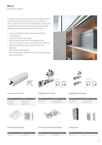
Rivvi Bi-Fold Door System
A superior Italian manufactured bi-folding door system, this range is high value for money and provides you with a superb solution for bi-folding kitchen, pantry and wardrobe doors. Extremely smooth and quiet system ideally suited to kitchen and bathroom fit-outs. • Super smooth sliding with industrial grade ball bearing rollers • Systems for doors up to 50kg • Suits timber or aluminium framed glass doors • Left hand roller & hinge moves to left when opening • Right hand roller & hinge moves to right when opening • No bottom track required • Soft closing when used with soft close cabinet hinges (order separately)
Top View
28
Top View
33
LH
RH
LH
RH
Aluminium Top Track
25kg Roller and Hinge
50kg Roller and Hinge
Part No. CT1200C.ALU
Description 1200mm track
Part No. CTS.25R.ZP
Description Right hand hinge
Part No. CTS.50R.ZP
Description Right hand hinge
CT1650C.ALU
1650mm track
CTS.25L.ZP
Left hand hinge
CTS.50L.ZP
Left hand hinge
CT2400C.ALU
2400mm track
42 42
28 28
5,5 5.5
Centre Bi-Fold Hinge
Twin Cup Centre Bi-Fold Hinge
Hinge Cover
Part No. CSHC.ZP
Part No. ACHB35.NP
Part No. CTSC.GY
Finish Zinc Plated
27,5 27.5
110 110
32 32
50 50
53 53
Finish Nickel Plated
Finish Grey
35
Rivvi Bi-Fold Door System Installation Details
Standard side hinges
Soft Closing effect simply by using soft close hinges
Maximum Stability
Cover
Vertical force Horizontal force
36
Rivvi Bi-Fold Door System Installation Dimensions
50kg System
37
Rivvi Bi-Fold Door System Installation Details
1 Door application
2 Door application
38
Rivvi Bi-Fold Door System Installation Dimensions
25kg System
39
Rivvi Bi-Fold Door System Installation Dimensions
Standard Central Hinges
T = top/bottom panel thickness
52
Adjustable Central Hinges
part no. ACHB35.
T = top/bottom panel thickness 40
Rivvi Bi-Fold Door System Installation Dimensions
Standard Central Hinges
part no. CSHC.ZP.FG
T = top/bottom panel thickness
52
Adjustable Central Hinges
part no. ACHB35.NP.FG
T = top/bottom panel thickness
41
Rivvi Soft close wardrobe system
Our Rivvi soft close wardrobe system is available in two options, to suit doors up to 70kg. The systems offer smooth rolling action due to high quality ball bearings, large diameter wheels, function exceptionally well and are super simple to install.
• Smooth rolling action due to high quality ball bearing wheels. • Suitable for doors 18-22mm thick, up to 70kg per door. • Suitable for 2, 3 or 4 door installations. • Fully adjustable rollers with anti-jump feature on top guides. • Concealed soft-close action in both left & right directions. • Bottom track available in surface mount or recessed versions. • Fast and simple to install. • Matching handle profiles suit 16mm or 18mm board. • Available in Aluminium, White and Matt Black. • Note: For 3 door systems order 1 x 2 door system + 1 x 3rd door system (Refer to page 47 for instructions)
60kg Standard System
70kg Premium System
Part No. RV60.100.2
Description 2 door roller & guide set
Part No. RV70.300.2
Description 2 door roller & guide set
RV60.100.C3
3rd door roller & guide set
RV70.300.C3
3rd door roller & guide set
Door Thickness
3.6m Top track
3.6m Bottom track
3.6m Recessed track
2.6m Handle profile
Part No. RV70.2910.36.ALU
Finish Aluminium
Part No. RV70.7108.36.ALU
Finish Aluminium
Part No. RV70.7520.36.ALU
Part No.
Finish Aluminium
Size
RV70.2910.36.MBL
Matt Black
RV70.7108.36.MBL
Matt Black
RV70.2900.26
Matt Black
18mm
RV70.2910.36.MWH White
Finish Aluminium
RV70.7108.36.MWH White
White Aluminium RV70.2905.26
Matt Black White
42
16mm
Rivvi Soft Close Wardrobe System Product Information
Upper Dampers
Soft Close Top Track
Door Handle Profile Upper Sliders
Bottom Track
Rollers
Standard Bottom Track
Recessed Bottom Track
43
Rivvi Soft Close Wardrobe System Planning Dimensions: 2 Doors - No Handle Profiles
SOFT CLOSING SOFT SOFT CLOSING CLOSING
SOFT CLOSING SOFT SOFT CLOSING CLOSING
max 30 min 16 max max30 30 min min16 16
79 79 79
max 30 min 16 max max30 30 min min16 16
( L/2 ) + 13 ((L/2 L/2))++13 13
25 25 25 max 30 min 16 max max30 30 min min16 16
L LL
25 25 25
44
max 30 min 16 max max30 30 min min16 16
L LL
( L/2 ) + 13 ((L/2 L/2))++13 13
79 79 79
SRG 100 Rivvi Soft Close Wardrobe System Teknik ÖlçülerM03 • Technical Data Planning Dimensions
mensions 79 79 27 27
39 39
32
40 40
10
10 Z
10 10
32 32 40 40 Width to height ratios to ensure correct 10 of doors operation ZDoor10 Z Door Height Z500 width Z ≤ 1500
40
10 10
Z
32 32
X X
W
W W
EB EB Y 12 Y 12
Door Thickness W W
Article
Installed Width EB
16
SRG 100
18
SRG 100
X
Y
Z Door Thickness (W)
39
23
11
12
39
21
9
10
39
20
8
9
20
SRG 100
39
19
7
8
22
SRG 100
39
17
5
6
≤ 2000
900
≤ 2200
1000 - 1500
≤ 2500
EB EB
X X
W W
Installed Width (EB)
16
39
18
39
19
39
20
39
22
39
Distance between doors X 23
Y 11
Z 12
21
9
10
20
8
9
19
7
8
17
5
6
6
A A
60kg Rollers
LW
64 64
LW LW
5 9
9 9
7 7
5 5
X = 40mm (60kg rollers) 43mm (70kg Rollers)
28
Y 12 Y 12
35
≤ 1700
800
7 28 28 54 29 54
81 81 70kg Rollers
6
≤ 1700
700
Distance between doors
SRG 100
10
7 7 55
2
W W
DOOR LENGHT = LW - 40 (mm)
54
8
W
19
5 9
64 64
28
X EB
61
W W
64
W
600
DOORLENGHT LENGHT= =LW LW- X - X(mm) (mm) DOOR
27
*
39 39
35 35
*When using recessed track, add 5mm to height of door
lebilir. / Recommended installation dimensions. All technical details arre subject to change by Albatur Co.
06
produces quality
45
Rivvi Soft Close Wardrobe System Planning Dimensions: 2 Doors - Outside door
16
min.32
10
10
32
32
96
194
96
min.32
73 39
82
61
64
9
5 70kg Roller
46
7 60kg Roller
min.32
Rivvi Soft Close Wardrobe System Planning Dimensions: 2 Doors - Using Handle Profiles
Door Thickness Door Thickness SOFT CLOSING SOFT CLOSING
SOFT CLOSING SOFT CLOSING
max 30 min 16 max 30 min 16
max 30 min 16 max 30 min 16
L L
max 30 min 16 max 30 min 16
25
(L/2)+13
25
(L/2)+13 (L/2)-17
L L
(L/2)+13
25
(L/2)+13 (L/2)-17
25
(L/2)-17
max 30 min 16 max 30 min 16
(L/2)-17
47
Rivvi Soft Close Wardrobe System Planning Dimensions: 2 Doors - Inside door
16
10 32 min.32 min.32
96
39
39
96 96
73 73
82
82
64
61
64 9
7
5 70kg Roller
70kg Roller
48
32
10 10 32 32
96
61
9
10
5
194
7
60kg Roller
60kg Roller
min.32 min.32
min.32 min.32
Rivvi Soft Close Wardrobe System Planning Dimensions: 3 Doors
SOFT CLOSING
UPPER SLIDER WITHOUT ACTIVATOR
UPPER SLIDER WITHOUT ACTIVATOR
L
79 25
25 (L/3)+17 L
18 79 25
25 (L/3)+17 (L/3)-13 49
Rivvi Soft Close Wardrobe System Planning Dimensions: 3 Doors
32
96
32
32
73
96 64
73
64
7
7
10 32
X
(X+20) X
(X+20)
10 32
32
10 32
10 32
96
96
32
32 32
32
96
96
X
10 32
X
10 32
10 32
10 32
64 96
32
32
32
96
96
10 32
50
10 32
64 96
32
73 32
96
32
64
7
73 32
7
EXTERNAL DOOR ASSEMBLY
lNTERNAL DOOR ASSEMBLY
lNTERNAL DOOR ASSEMBLY
10 32
EXTERNAL DOOR ASSEMBLY
X
(X+20) X
(X+20)
10 32
73 32
96
32
64
7
73 32
7
Rivvi Soft Close Wardrobe System Installation
Installation
1
Installing upper dampers
3
Installing bottom track
2
Installing top track
Ø3,5 x 16
Ø3,5 x 16
Internal door
External door
Ø3,5 x 16 All connections
4
Install running and guiding components
5
Install running and guiding components
Ø3,5 x 16 All connections
51
Rivvi Soft Close Wardrobe System Installation
6 Internal Door: Place upper slider inside of behind top rail
7 External Door: Place upper slider inside of front of top rail
8
52
Adjust door height
9
Adjust anti jump for security
Rivvi 40kg Adjustable Sliding Door System Information
• Smooth rolling action due to high quality ball bearing rollers. • Designed for doors 18mm thick and up to 40kg per door. Can also be used on doors 16mm thick • Guided roller and top catch prevent doors from coming off the track. • Suitable for 2, 3 or 4 door installations. • Height adjustable bottom rollers. • Recessed top and bottom aluminium tracks. Description Roller door and guide set
Part No. RV40.6000.1
One set contains 2 bottom rollers and 2 top guides
Door Thickness
2.6m Handle profile (optional)
Aluminium Track - 3m Part No. RV40.6001.30.ALU
Finish Aluminium
Part No.
Finish Aluminium
Size
RV70.2900.26
Matt Black
18mm
Use for top and bottom track
White Aluminium RV70.2905.26
Matt Black
16mm
White
53
Rivvi 40kg Adjustable Sliding Door System Planning Dimensions - 2 Doors 18mm thick
12
Min. 40
11
Min. 40
12 18
12
12
Min. 40 Ø3 5
11
Min. 4048 12
Min. 40
5 Ø3
max 30 min 16
L
max 30 min 16
12 18
64 48
12 18
5 Ø3
Min. 40
64 48
Min. 40
12
48 64
Min. 40
48 64 48
12
Ø35
12 18
12
48 64
Ø3 5
Min. 40
12 18
12
11
Ø35
12 18
64
11
Planning Dimensions - 2 Doors with handle profile Min. 40 64 48
max 30 min 16
18
18
L 7
max 30 min 16
25 18
54
( L / 2 ) - 17 ( L / 2 ) + 13
2800
( L / 2 ) + 13 ( L / 2 ) - 17 2800
2800
2800
2800
2800
( L / 2 ) - 17 ( L / 2 ) + 13
25
2800
7 2800
18
( L / 2 ) + 13 ( L / 2 ) - 17
Rivvi Light Duty Sliding Door System Information
• Suitable for doors 16-18mm thick and up to 15kg per door. • Guided roller & top catch prevent doors from coming off the track. • Suitable for 2, 3 or 4 door installations. • Height adjustable bottom rollers. • Recessed top and bottom aluminium tracks.
Installation Dimensions Minimum G+5 5 10 26
Minimum G+5
26 5
10 26
26 10
32
10
32
G
G
5
5
G
G
12.5mm
42 32 5.5mm
10
42 32
10
26
22 26 10
7.6mm
Description Roller door & guide set
Part No. RV15.6510.1
Aluminium track - 3m
RV15.6520.30.ALU
One set contains 2 bottom rollers and 2 top guides
5
26
22 26
6 8
10 5
6 8 55
Rivvi Top Hung Sliding Door System Information
• Adjustable top hung captive roller with mounting brackets. • Suitable for doors 18-50mm thick and up to 60kg per door. • Plastic bottom guide. • Aluminium top track with optional wall mounting brackets.
Installation Dimensions
27
35 Min . 18 mm Max . 23 mm 24 20
35mm
32mm
16mm
Description Roller door & guide set
Part No. RV60T.7340.1
Aluminium track - 3m
RV60T.7222.30.ALU
9 14 8
One set contains 2 bottom rollers and 2 top guides
56
Rivvi Barn Door Sliding Door System
57
Rivvi Barn Door Sliding Door System Information
• Adjustable top hung exposed captive barn door style rollers with mounting brackets. • Smooth rolling action due to high quality ball bearing rollers. • Top track is wall mounted and hardware is designed to be exposed. • Suitable for doors 32-50mm thick, up to 80kg per door. • Supplied as a full kit with 2m track in black only. • Black aluminium top track with wall mounting brackets. • Two way soft-closing Description
Part No. RV80BD.8820.20.MBL
Barn door style sliding door system
Installation Dimensions
40 40
40 Door measurement = opening size + 80mm Door measurement = opening size + 80mm
40
40
40
9 9
58
WIND
59
Salice Wind Lift System
Salice Wind is an innovative lift-up door systems that is easy to install and adjust, is compact, and available in soft-close or push-to-open versions. Consistent door and cabinet setout simplifies the design and specification. • • • • • • • •
Soft closing or push to open option available Door height from 220mm to 600mm Door weight up to 25kg 85° - 94° opening angle (Selectable) Adjustable spring strength Sold per door set Black or white covers available. (Ordered separately) Extra bracket to be used in conjunction with standard Salice Wind system when fixing to the top of a cabinet • Can also be used to allow the installation of additional systems on very large doors • Refer to strength charts on page 92 to select the correct colour springs for your application. • Door weight can be calculated for 18mm thick MDF door by: Height of door (in meters) x Width of door (in meters) x 14
Soft close mechanisms
60
Push to open mechanisms
Covers
Catch & retaining catch recommended - see page 96
Part No. SAL.WDSC1W
Strength Code W
Spring Colour 1 x White
Part No. SAL.WDPO1W
Strength Code W
Spring Colour 1 x White
Part No. SAL.WDCV.MBL.FG
Finish White
SAL.WDSC1Y
D
1 x Yellow
SAL.WDPO1Y
D
1 x Yellow
SAL.WDCV.WH.FG
Matt black
SAL.WDSCY.FG
I
2 x Yellow
SAL.WDPOY.FG
I
2 x Yellow
SAL.WDSCB.FG
F
2 x Black
SAL.WDPOB.FG
F
2 x Black
SAL.WDSCR.FG
S
2 x Red
SAL.WDPOR.FG
S
2 x Red
Salice Wind Installation Instructions
Flap door lift system fixed to the cabinet sides. • Drilling of the door ø35. • 13 mm deep cup. • 85° opening with stop device (premounted). • 94° opening without stop device. • Possible drilling distance on the door (K): from 3 to 7 mm.
Drilling Patterns
Space needed to open the door
K 3
=
D1 16
T= 16 17 18 19 20 21 22 23 24 25 26 27 28 K=3 A=min 0 0.1 0.1 02 0.2 0.3 0.5 0.6 0.7 0.9 1.1 1.8 2.7
4
=
17
K=4 A=min 0
0.1 0.1 02 0.2 0.3 0.4 0.6 0.7 0.9 1.1 1.3 2.1
5
=
18
K=5 A=min 0
0.1 0.1 02 0.2 0.3 0.4 0.6 0.7 0.9 1.1 1.3 1.5
6
=
19
K=6 A=min 0
0.1 0.1 02 0.2 0.3 0.4 0.6 0.7 0.9 1.1 1.2 1.5
7
=
20
K=7 A=min 0
0.1 0.1 02 0.2 0.3 0.4 0.6 0.7 0.8 1.0 1.2 1.4
61
Salice Wind Installation Instructions
Fixing the plates to the cabinet sides
L
R
Deploying the system to the cups This operation is tool free
62
Fixing the cups to the door
Installing the system to the plates. Insert the system until back fixing is engaged. This operation is tool free.
Salice Wind Installation Instructions
Installing the covers
WARNING! Security cable ties.
Remove the cable ties only at the end of the assembly. Use the instructions and the QR Code attached to the systems.
Adjustments 1. Adjustment of the spring strength. 2. Adjustment of the decelerating effect. 3. Extension/adjustment of opening angle of door.
4. Height adjustment of the door from - 2 to +2. 5. Sideways adjustment of the door from - 2 to+2. 6. Depth adjustment of the door from - 1 to +3.
63
Salice Wind Installation Instructions
Removal of the covers
Disconnecting the system from the cups. This operation is tool free.
64
Disassembly of the system. Press the back lever and pull out the system. This operation is tool free.
Salice Wind Installation Instructions
• Extra bracket to be used in conjunction with standard Salice Wind system when fixing to the top of a cabinet • Can also be used to allow the installation of additional systems on very large doors • Supplied in a set of 2 brackets with covers • Mechanisms must be ordered separately. Part No. SAL.WDSBK.WH
Finish White
SAL.WDSBK.MBL
Matt black
Drilling Patterns
Space needed to open the door
K 3 4 5 6 7
= = = = =
D1 13 14 15 16 17
T= K=3 A=min K=4 A=min K=5 A=min K=6 A=min K=7 A=min
16 0 0 0 0 0
17 0.1 0.1 0.1 0.1 0.1
18 0.1 0.1 0.1 0.1 0.1
19 20 21 22 23 24 25 26 27 28 02 0.2 0.3 0.5 0.6 0.7 0.9 1.1 1.8 2.7 02 0.2 0.3 0.4 0.6 0.7 0.9 1.1 1.3 2.1 02 0.2 0.3 0.4 0.6 0.7 0.9 1.1 1.3 1.5 02 0.2 0.3 0.4 0.6 0.7 0.9 1.0 1.2 1.5 02 0.2 0.3 0.4 0.6 0.7 0.8 1.0 1.2 1.4
65
Salice Wind Installation Instructions
For cabinets that require a third system
K 3 4 5 6 7
= = = = =
D1 13 14 15 16 17
For corner cabinets
K 3 4 5 6 7
66
= = = = =
D1 13 14 15 16 17
Salice Wind Installation Instructions
Fixing the carriers to the top of the cabinet.
Installing the system to the plates. This operation is tool free.
Installing the covers
67
Salice Wind Installation Instructions
68
Removal of the covers
Dissassembly of the system Press the back lever and pull out the system. This operation is tool free.
Unfasten the plates from the carriers
Unfasten the carriers
Salice Wind Charts
Determine which system to use for a particular door size and weight. For doors with larger weight and dimensions, it is possible to use more than two systems on the same door. These systems can be fixed to intermediate sides or, if not possible, by using the optional carrier for the plate (page 88). In this case please carefully check the chart concerning the door overlay on top of the cabinet (D1). We recommend that all applications are verified by a practical trial.
1 x White Spring 6 0.8 0.6
Door weight (Kg)
0.4
5 0.8
0.2
0.6 0.4
4 0.8
0.2
0.6 0.4
3 0.8
0.2
0.6 0.4
2 0.8
0.2
0.6 0.4 0.2
1
220
280
320
360
400
440
480
520
Door height (mm)
1 x Yellow Spring 8 0.8 0.6 0.4
7 0.8
0.2
0.6
Door weight (Kg)
0.4
6 0.8
0.2
0.6 0.4
5 0.8
0.2
0.6 0.4
4 0.8
0.2
0.6 0.4
3 0.8
0.2
0.6 0.4
2 0.8
0.2
0.6 0.4
1
0.2
220
280
320
360
400
440
480
520
560
600
Door height (mm)
69
Salice Wind Charts 15 0.8 0.6 0.4
14 0.8
0.2
0.6 0.4
13 0.8
2 x Yellow Springs
0.2
0.6 0.4
12 0.8
0.2
0.6 0.4
11 0.8
0.2
0.6
Door weight (Kg)
0.4
10 0.8
0.2
0.6 0.4
9 0.8
0.2
0.6 0.4
8 0.8
0.2
0.6 0.4
7 0.8
0.2
4 WIND
0.6 0.4
6 0.8
0.2
3 WIND
0.6 0.4
5 0.8
0.2
0.6 0.4
4 0.8
0.2
2 WIND
0.6 0.4
3 0.8
0.2
0.6 0.4 0.2
2
320
360
400
440
480
520
560
600
Door height (mm) 20 0.8 0.6 0.4
19 0.8
0.2
0.6
2 x Black Springs
0.4
18 0.8
0.2
0.6 0.4
17 0.8
0.2
0.6 0.4
16 0.8
0.2
0.6 0.4
15 0.8
0.2
0.6 0.4
14 0.8
0.2
Door weight (Kg)
0.6 0.4
13 0.8
0.2
0.6 0.4
12 0.8
0.2
0.6 0.4
11 0.8
0.2
4 WIND
0.6 0.4
10 0.8
0.2
0.6 0.4
9 0.8
3 WIND
0.2
0.6 0.4
8 0.8
0.2
0.6 0.4
7 0.8
0.2
0.6
2 WIND
0.4
6 0.8
0.2
0.6 0.4
5 0.8
0.2
0.6 0.4
4
70
0.2
320
360
400
440
480
520
Door height (mm)
560
600
Salice Wind Charts
2 x Red Springs 24 0.8 0.6 0.4
23 0.8
0.2
0.6 0.4
22 0.8
0.2
0.6 0.4
21 0.8
0.2
0.6 0.4
20 0.8
0.2
0.6 0.4
19 0.8
0.2
0.6 0.4
18 0.8
0.2
0.6 0.4
Door weight (Kg)
17 0.8
0.2
0.6 0.4
16 0.8
0.2 0.6
0.4
15 0.8
0.2
0.6 0.4
14 0.8
0.2
4 WIND
0.6 0.4
13 0.8
0.2
0.6 0.4
12 0.8
0.2
3 WIND
0.6 0.4
11 0.8
0.2
0.6 0.4
10 0.8
0.2
0.6 0.4
9 0.8
0.2
0.6
2 WIND
0.4
8 0.8
0.2
0.6 0.4
7 0.8
0.2
0.6 0.4
6
0.2
320
360
400
440
480
520
560
600
Door height (mm)
71
Salice Push Catch Push Application
For part numbers and drilling patterns for Salice magnetic push and catch see page 96 For cabinets over 400mm high, it is suggested that one release device is used. SAL.DP39XXG
SAL.DPMSNG
For cabinets less than 400mm high, it is suggested that two release devices are used.
SAL.DP39XXG
SAL.DPMSNG SAL.DPMSNG
72
Pacta is a compact hinge for fall flaps which operates without the need for additional stays or cables. Pacta confers a decelerated opening action and the fall of the door is gradual and controlled. In the fully-open position, the door and base panel are aligned, creating a uniform and flat surface. Available with Push self-opening system, Pacta comes in a variety of f inishes. Its applications are numerous: in living room and kitchen cabinets, to create desks in children’s furniture or for writing surfaces and table extensions in hotel furniture.
73
Pacta Technical Information
Hinge for flap doors with decelerated opening. Push opening. Fixing to the base of the cabinet with longitudinal snap-on mounting plate (BAPGR29/16). Standard drilling of the door ø 35. 13 mm deep cup. 90° opening. Fixed K = 4.5 mm. Pacta is tested and certified to level 3 of UNI EN 15828:2010 Drilling patterns
Space needed to open the door
74
Pacta Technical Information
Hinge for flap doors with decelerated opening. Sprung closing action. Fixing to the base of the cabinet with longitudinal snap-on mounting plate (BAPGR29/16). Standard drilling of the door ø 35. 13 mm deep cup. 90° opening. Fixed K = 4.5 mm. Pacta is tested and certified to level 3 of UNI EN 15828:2010 Drilling patterns
Space needed to open the door
75
Pacta Assembly Instructions Adjustments
Fix the security screw
Installing the smove Clip the narrow end of the smove into position. This operation is tool free.
76
Pacta Assembly Instructions Fixing the mounting plate to the cabinet
Fixing the hinge to the door
Mounting the door onto the cabinet Clip the hinge arm onto the mounting plates. This operstion is tool free.
77
Pacta Assembly Instructions Assembly Instructions for the central hinge We suggest that you use the central hinge for cabinets over 900mm width. Install the cover cap onto the hinge according to the drawing and then screw fix the hinge to the cabinet.
After fixing the hinge, make any adjustments required
Overall view of the mounted system
78
Install the cover cap onto the hinge on the cabinet side
Pacta Assembly Instructions Lift the flap slightly and clip the other end of the smove into position. This operation is tool free.
Installing the cover Firstly install the cover on the hinge arm and then to the cup.
Dimensions
79
Pacta Disassembly Instructions Remove the security screw
Unfasten the hinge from the mounting plate with a screwdriver
80
Pacta Disassembly Instructions Removal of the cover
Disasembly of the smove Lift the flap slightly and unclip the back of the smove using a screwdriver.
Remove the other end of the smooth
81
Pacta Colour of the cover cap for the central hinge FRCK59RXXX1 White
Pacta Charts Charts to determine which smove is to be used for a particular door size and weight. We recommend that all applications are verified by a practical trial.
DRBWXXYXI
82
Pacta Charts DRBWXXYXI
DRBIXXYXI
83
Pacta Charts DRBSXXYXI
84
Salice Evolift - Push Catch Installation Instructions
Magnetic push - recessed magnetic release device and retaining catches
Part No. SAL.DPMSNG
Finish Grey
Description Catch
SAL.DP39XXG
Grey
Retaining Catch
ø10 S
Application of the standard magnetic catch Drill a hole Ø 10 mm and min. 40 mm depth in the top, the side or the base panel of the cabinet. Insert the release device into the hole.
40 min
2.5 T
Inserting the adjustable magnetic catch When using the magnetic catch and release latch together, the holding strength of the door against the cabinet is considerably increased (30%), helping to avoid accidental opening. Installation requires a drilled hole Ø15mm and 11mm deep. Depth adjustment from -0.5 mm to +2.5 mm.
ø 10 S
40 min
2.5 T
ø 15
ø 16.6
9.5 ø 15
ø 16.6
85
Door Weight Calculation Table - 18mm MDF Table shows values for 18mm thickness and density 720kg/m³
Door Height (mm)
Door Width (mm) 200
250
300
350
400
450
500
500
1.3
600
1.6
700 800
550
600
650
700
1.6
1.9
2.3
2.6
2.9
1.9
2.3
2.7
3.1
3.5
1.8
2.3
2.7
3.2
3.6
2.1
2.6
3.1
3.6
4.1
900
2.3
2.9
3.5
4.1
4.7
1000
2.6
3.2
3.9
4.5
1100
2.9
3.6
4.3
5.0
1200
3.1
3.9
4.7
750
800
850
3.2
3.6
3.9
4.2
4.5
4.9
5.2
5.5
3.9
4.3
4.7
5.1
5.4
5.8
6.2
6.6
4.1
4.5
5.0
5.4
5.9
6.4
6.8
7.3
7.7
4.7
5.2
5.7
6.2
6.7
7.3
7.8
8.3
8.8
5.2
5.8
6.4
7.0
7.6
8.2
8.7
9.3
9.9
5.2
5.8
6.5
7.1
7.8
8.4
9.1
9.7
10.4
11.0
5.7
6.4
7.1
7.8
8.6
9.3
10.0
10.7
11.4
12.1
5.4
6.2
7.0
7.8
8.6
9.3
10.1
10.9
11.7
12.4
13.2
1300
3.4
4.2
5.1
5.9
6.7
7.6
8.4
9.3
10.1
11.0
11.8
12.6
13.5
14.3
1400
3.6
4.5
5.4
6.4
7.3
8.2
9.1
10.0
10.9
11.8
12.7
13.6
14.5
15.4
1500
3.9
4.9
5.8
6.8
7.8
8.7
9.7
10.7
11.7
12.6
13.6
14.6
15.6
16.5
1600
4.1
5.2
6.2
7.3
8.3
9.3
10.4
11.4
12.4
13.5
14.5
15.6
16.6
17.6
1700
4.4
5.5
6.6
7.7
8.8
9.9
11.0
12.1
13.2
14.3
15.4
16.5
17.6
18.7
1800
4.7
5.8
7.0
8.2
9.3
10.5
11.7
12.8
14.0
15.2
16.3
17.5
18.7
19.8
1900
4.9
6.2
7.4
8.6
9.8
11.1
12.3
13.5
14.8
16.0
17.2
18.5
19.7
20.9
2000
5.2
6.5
7.8
9.1
10.4
11.7
13.0
14.3
15.6
16.8
18.1
19.4
20.7
22.0
2100
5.4
6.8
8.2
9.5
10.9
12.2
13.6
15.0
16.3
17.7
19.1
20.4
21.8
23.1
2200
5.7
7.1
8.6
10.0
11.4
12.8
14.3
15.7
17.1
18.5
20.0
21.4
22.8
24.2
2300
6.0
7.5
8.9
10.4
11.9
13.4
14.9
16.4
17.9
19.4
20.9
22.4
23.8
25.3
2400
6.2
7.8
9.3
10.9
12.4
14.0
15.6
17.1
18.7
20.2
21.8
23.3
24.9
26.4
2500
6.5
8.1
9.7
11.3
13.0
14.6
16.2
17.8
19.4
21.1
22.7
24.3
25.9
27.5
2600
6.7
8.4
10.1
11.8
13.5
15.2
16.8
18.5
20.2
21.9
23.6
25.3
27.0
28.6
Door weight can be calculated for 18mm thick MDF door by: Height of door (in meters) x Width of door (in meters) x 14
Door Weight Calculation Table - 16mm Chipboard Table shows values for 16mm thickness and density 670kg/m³
Door Height (mm)
Door Width (mm)
86
200
250
300
350
400
450
500
550
600
650
700
750
800
850
500
1.1
1.3
1.6
1.9
2.1
2.4
2.7
2.9
3.2
3.5
3.8
4.0
4.3
4.6
600
1.3
1.6
1.9
2.3
2.6
2.9
3.2
3.5
3.9
4.2
4.5
4.8
5.1
5.5
700
1.5
1.9
2.3
2.6
3.0
3.4
3.8
4.1
4.5
4.9
5.3
5.6
6.0
6.4
800
1.7
2.1
2.6
3.0
3.4
3.9
4.3
4.7
5.1
5.6
6.0
6.4
6.9
7.3
900
1.9
2.4
2.9
3.4
3.9
4.3
4.8
5.3
5.8
6.3
6.8
7.2
7.7
8.2
1000
2.1
2.7
3.2
3.8
4.3
4.8
5.4
5.9
6.4
7.0
7.5
8.0
8.6
9.1
1100
2.4
2.9
3.5
4.1
4.7
5.3
5.9
6.5
7.1
7.7
8.3
8.8
9.4
10.0
1200
2.6
3.2
3.9
4.5
5.1
5.8
6.4
7.1
7.7
8.4
9.0
9.6
10.3
10.9
1300
2.8
3.5
4.2
4.9
5.6
6.3
7.0
7.7
8.4
9.1
9.8
10.5
11.1
11.8
1400
3.0
3.8
4.5
5.3
6.0
6.8
7.5
8.3
9.0
9.8
10.5
11.3
12.0
12.8
1500
3.2
4.0
4.8
5.6
6.4
7.2
8.0
8.8
9.6
10.5
11.3
12.1
12.9
13.7
1600
3.4
4.3
5.1
6.0
6.9
7.7
8.6
9.4
10.3
11.1
12.0
12.9
13.7
14.6
1700
3.6
4.6
5.5
6.4
7.3
8.2
9.1
10.0
10.9
11.8
12.8
13.7
14.6
15.5
1800
3.9
4.8
5.8
6.8
7.7
8.7
9.6
10.6
11.6
12.5
13.5
14.5
15.4
16.4
1900
4.1
5.1
6.1
7.1
8.1
9.2
10.2
11.2
12.2
13.2
14.3
15.3
16.3
17.3
2000
4.3
5.4
6.4
7.5
8.6
9.6
10.7
11.8
12.9
13.9
15.0
16.1
17.2
18.2
2100
4.5
5.6
6.8
7.9
9.0
10.1
11.3
12.4
13.5
14.6
15.8
16.9
18.0
19.1
2200
4.7
5.9
7.1
8.3
9.4
10.6
11.8
13.0
14.2
15.3
16.5
17.7
18.9
20.0
2300
4.9
6.2
7.4
8.6
9.9
11.1
12.3
13.6
14.8
16.0
17.3
18.5
19.7
21.0
2400
5.1
6.4
7.7
9.0
10.3
11.6
12.9
14.2
15.4
16.7
18.0
19.3
20.6
21.9
2500
5.4
6.7
8.0
9.4
10.7
12.1
13.4
14.7
16.1
17.4
18.8
20.1
21.4
22.8
2600
5.6
7.0
8.4
9.8
11.1
12.5
13.9
15.3
16.7
18.1
19.5
20.9
22.3
23.7
87
1300 222 600 www.furnwaregroup.com.au 88
Door Systems Brochure Version 3