November/December | 2014 | Vol. 4, No. 6
OIL CHANGES
The frequency debate
ANNUAL TECHS HELPING TECHS ISSUE THREAD CHASING: Restoring fastener threads ENGINE PRE-OILING: A critical step for fresh engines
Circle 101 on Reader Service Card
November/December | 2014 | Vol. 4, No. 6
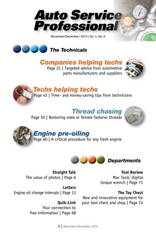
The Technicals
Companies helping techs Page 21 | Targeted advice from automotive parts manufacturers and suppliers
Techs helping techs T Page 42 | Time- and money-saving tips from technicians Pa
Thread chasing Page 50 | Restoring male or female fastener threads
Engine pre-oiling E Page 60 | A critical procedure for any fresh engine Pa
Departments Straight Talk The value of photos | Page 6 Letters Engine oil change intervals | Page 13 Quik-Link Your connection to free information | Page 68
Tool Review Mac Tools’ digital torque wrench | Page 71 The Toy Chest New and innovative equipment for your tool chest and shop | Page 74
4 | November/December 2014
Circle 102 on Reader Service Card
The value of photos Mike Mavrigian | Editor
S
ince it seems as though just about everyone these days has a “smart” phone glued to their head or stashed in their pocket 24 hours a day, we may as well take advantage of the camera feature of these phones while inspecting, diagnosing and repairing customer vehicles. When performing an engine oil change, you perform a cursory inspection of the belly, checking the condition of tie rod ends, lower radiator hose, transmission cooler lines, fuel lines, brake lines, CV joints, U-joints, etc. When you fnd a leaking trans output seal, rusty fuel lines or leaking shocks, you may make a mental note or record your fndings on paper. However, as we all know, a picture is worth a thousand words (OK, maybe with infation it’s now worth 10,000 words). On occasion, a frst-time customer may not believe you, and may assume you’re simply trying to rack up the bill. By showing them photos with documented proof of the problem, they’re more inclined to OK the work. By the same token, after diagnosing a problem and after making the necessary repairs, by snapping a few photos of the work, you’re able to show positive proof that the repair and/or parts replacement has indeed been performed. With the
high-speed cellular technology provided by today’s phones, you’re able to easily text the customer and email photos in order to have the work authorized even when the customer isn’t in the shop. Once the photos have been taken (and possibly reviewed by the customer), instead of deleting them, upload them to the customer’s fle for possible future reference. This can provide an aid for you during future diagnosis (for example, the engine threw a P0401 EGR insuffcient fow code. Maybe you determined that the valve was OK but the passage was clogged with deposits, and you cleaned it out. If the vehicle comes back in with the same code, you have a reminder of what you did previously and can move on to checking other potential areas). Or maybe you replaced an O2 sensor, and two months later the vehicle is back with the customer complaining of a big dent in the foorpan, assuming you did that when hoisting the vehicle on your lift. When you review the photos you took, you can prove that the foor was not dented when in your shop. The culprit may end up being the customer’s son who improperly jacked up the car while running cables for his insane sound system.
6 | November/December 2014
Circle 103 on Reader Service Card
While you may have a loyal customer base that doesn’t question your diagnosis or work, there’s always the skeptical (or should we say paranoid) customer who assumes that the world is out to get him or her by making suggestions and making unnecessary repairs. With today’s highquality smartphone camera technology, it’s easy to take the photos and just as easy to store and show them to the customer. In my shop, we photograph virtually every step of our work, not only to document the work for the customer’s beneft, but also to provide us with useful reference photos, especially during disassembly. Granted, my shop specializes in detailed vintage restorations where reference information is often critical for our technicians. Also, the type of customers that we deal with like the idea of having a “scrapbook” of the entire process for their review and
Circle 104 on Reader Service Card
as a reference for a buyer when and if they sell the vehicle. Although our need for photos may be excessive, by taking even a minimum of photos, the average shop can easily generate documented proof of both the problems and the repairs. If the customer questions anything along the way, you can refer to a photo and show proof positive that something was needed and/or that the repair was indeed performed. Granted, plenty of techs are currently generating these photo fles, so my suggestion is certainly nothing new. But for those of you who haven’t considered this type of routine record keeping, it’s something to think about. After all, those cell phones are sitting in your shirt or pants pocket anyway. Why not take advantage of them? ● Care to comment? Please email me at mike.mavrigian@bobit.com.
8 | November/December 2014
Circle 105 on Reader Service Card
3515 Massillon Rd., Suite 350, Uniontown, OH 44685 (330) 899-2200, fax (330) 899-2209 Website: www.autoserviceprofessional.com Editor: Mike Mavrigian Mike.Mavrigian@bobit.com Managing Editor: Lori L. Mavrigian Lori.Mavrigian@bobit.com Senior Editor: Joy Kopcha Joy.Kopcha@bobit.com Associate Editor: Ann Neal Ann.Neal@bobit.com Contributors: Bob Weber/Automotive Technical Writer Craig Truglia/Diagnostics & Driveability Specialist Bob Rodriguez/Hybrid & Alternative Fuel Specialist Advisory Board: Dan Paddy/Dan Paddy Service, Seville, OH Frank Dannemiller/Mobile Service & Repair Co., Wadsworth, OH Bob Fall/Fall Automotive Machine, Toledo, OH Scott Gressman/Gressman Powersports, Fremont, OH Ken Styer/Ohio Technical College, Cleveland, OH Greg McConiga/O’Daniel Automotive Restorations, Ft. Wayne, IN Art Director: Neal Weingart Neal.Weingart@bobit.com Production Manager: Karen Runion Karen.Runion@bobit.com Publisher: Greg Smith Greg.Smith@bobit.com Sales: Dan Thornton djtinc@gmail.com (734) 676-9135, mobile (313) 410-0945 Michele Vargo Michele.Vargo@bobit.com (330) 899-2200, fax (330) 899-2209 John Dyal, The Dyal Company John.Dyal@bobit.com (760) 451-5026 Marianne Dyal, The Dyal Company Marianne.Dyal@bobit.com (760) 451-9216 Customer/Subscription Service Tammy Katata, (800) 991-7702
Auto Service Professional is a Bobit Publication Executive offces: 3520 Challenger St. Torrance, CA 90503 Chairman (1961-2014): Edward J. Bobit CEO & President: Ty F. Bobit Chief Financial Offcer: Richard E. Johnson VP & COO: Cyndy Drummey
10 | November/December 2014
Engine oil change intervals Editorial hit a nerve with ASP readers In a recent editorial, I commented about the validity of extended oil change intervals that are commonly promoted today by auto makers (ASP September/October 2014 issue). My intent was to provide my own opinion, and not to promote the increased sale of oil (read the editorial in our digital edition on www.autoserviceprofessional.com). This topic has obviously hit a nerve among our readers. Following are just a few of the letters we’ve received regarding this subject.- Ed.
CHEAP INSURANCE Oil changes are cheap insurance, in my opinion. I have always changed the oil on all my vehicles around the 3,000 mile mark using a good quality oil and a new flter. I have never had a serious engine problem thanks to this regular engine maintenance. Any valve cover I may have pulled to reseal, or intake manifold, always showed a very clean engine inside. “Pay a little now, or a lot later,” I have found has held true through the years. One of the worst engines I have ever seen due to the lack of oil changes was a customer’s vehicle I worked on in a Chevrolet garage in the early 1990s. A customer’s vehicle with 23,000 miles on it came in with an engine knock. It was an Astro van that had been purchased new from our dealership. Records showed the only oil change was at 12,500 miles. The customer said they thought all they had to do was keep adding oil to keep the level up. Needless to say, pulling a valve cover in the vehicle to check the engine valve train showed the buildup of a black sludge throughout. The motor was toast, a prime example of what can happen when not changing your oil on a regular basis. Kurt Schleicher, Customer Service Rep U.S. AutoForce
FRESH IS GOOD Regarding Auto Service Professional’s recent editorial by editor Mike Mavrigian, I could not agree more. I took a variable valve timing (VVT) course a short time ago, and the #1 problem with all the VVT vehicles by all manufactures was sludge and dirty oil. And what do the manufactures do? They EXTEND the oil change intervals! Is this part of a hidden agenda? P.S.: When my customers ask me what oil to use, I tell them FRESH. Joel Sylvia S&S Auto Repair
CHANGE IT AND USE THE CORRECT OIL Mike, you are so on target with your comments. I have been in automotive service all my life — 35-plus years. Fluids have always been one of the most important things that will protect your investment, especially in today’s high technology vehicles. My company services over 5 million vehicles a year. I also maintain a technical service hot line. The reason I bring that up is because we feld a large number of oilrelated problem calls, more than we have, say, 10 years ago. One of the popular oil-related calls we get today concerns variable valve timing DTCs with the engine light on. Many of the newer models utilize these systems. We are fnding that customers don’t check their oil or anything under the hood like they used to. These VVT DTCs many times are caused by low oil levels or neglected oil systems. Because of this, if we fnd low or dirty oil we start the diagnostic by performing a good oil change with the proper oil, and clear the DTC and send the driver on their way. That
13 | November/December 2014
is the fx, in many cases. If the DTCs come back, and they will if there is a problem, then we get into some real diagnostics. Unfortunately, at this point any money that the customer saved on extended oil changes will now need to be spent on corrective services. In many cases, we fnd gummed-up solenoids, plugged oil passages or plugged screens. I could go on talking about VVT problems, but I think you get the point. One thing consumers need to know is that the proper oil viscosity is most important these days. Flow characteristics are most important to VVT systems and the high-tech valve train. Here is another oil change interval-related problem that we are seeing. In the past, tire rotations would get done every other oil change. Today, if you go with, say, the GM OLS system recommendation for an oil change, you may not see that car for 12 months, maybe even past 7,500 miles between oil changes. What if the tires don’t get rotated with every oil change? Tires can be fnicky if they are left on the same axle too long. Noise and abnormal wear is usually not reversible on a tire. This is another hidden expense to the extended oil change interval. We are seeing tires just getting destroyed due to lack of rotations. One more thing. This is a little off-thewall. Do you know that there is a new regulation out there that prohibits a service station from putting an oil change sticker on the windshield recommending the next service interval? We can only put the mileage and date the service was done last. I am not sure exactly how many states this applies to, but it is in most that we are in. As I said at the beginning, one of the most important things that will protect your investment is clean fuids. And if you’re worried about the environment, recycled oils today are just as good and sometimes better than new oil. Jim Lynch, Training Director Monro Muffer Brake Inc.
CHANGE IT, CHANGE IT In my varied, long mechanical experience (30 years with Ford, seven with Navistar
and Cat and two years with the present dealer) I have seen many oil-related failures and driven many so-called cheap vehicles for transportation. The one conclusion I have come to is that fuid changes are the only saving grace to keeping a vehicles engine running correctly. I once owned a 1986 Ford Tempo that survived 320,000 miles and was still was running perfectly when I sold it. I believe the key to its success was engine service every 3,000 to 5,000 miles and the trans serviced every 6,000 to 10,000 miles! The interesting part of this nine-year test was that it was serviced with components that were on sale at Kmart only, with no specifc brand in common. I have seen customers who swore up and down that the synthetic oil they are using did not have to be changed until 10,000 miles while I was changing their overhead camshaft with fat lobes. Or the time I talked for two hours to convince a customer to change the oil in his 7.3 Ford Powerstroke to remedy an oil foaming concern with synthetic. His comment after was, “WOW... it runs great!” In my new position, I have seen Mercedes-Benz recommending 10,000-mile intervals — and if neglected, engines frozen tight and full of sludge. My conclusion of all this is change fuids and change them often no matter what brand or type. You will be able to drive that vehicle until you are sick and tired of it and the body falls off! Jerry Wolhart, Service Manager Demaiois Buick,GMC
WHAT CUSTOMERS NEED TO KNOW I am in total agreement with Mike Mavrigian’s editorial about the need to change engine oil on a more frequent basis. I wrote the following little sample letter specifcally to make a point for potential customers regarding the benefts of a 3,000mile oil change. This is just an example of a message that could be provided to customers in order to educate them. I have not yet sent this to anyone to solicit business:
14 | November/December 2014
Circle 106 on Reader Service Card
“Dear customer, “You may have heard that the 3,000-mile oil change is no longer necessary. However, it’s actually more necessary than ever. Here’s why: Today’s cars are more sophisticated than before, as I’m sure you know. And they cost more. And likely you will keep your car quite a long time as it’s a substantial investment. “In the ‘old days,’ it might have been easier for you to know when something was wrong with your car and identify the problem. As you know, it’s not as easy to do so these days and, as always, small problems can lead to bigger ones if not taken care of properly. “We at Acme Auto know cars well and would like to get to know yours better. We’d like to get to know you better, as well. Therefore, we suggest the both of you stop in to see us every 3,000 miles — ostensibly for an oil change — which we will do promptly and at a very competitive price. This is not only a good investment for the longevity of your engine when done frequently, but provides an opportunity for us to see how the engine is doing based on the condition of the oil. It also gives us a chance to have a look at the general condition of your car and perhaps discuss any concerns you have — primarily with your car — but, hey, there’s always time for a good customer like you. “Our oil change equipment is in place and there’s a fresh pot of coffee waiting. “Don’t be a stranger. “Sincerely, Joe Owner, Acme Auto” John Fischer Fischer Auto
FREQUENT OIL CHANGE = FREQUENT INSPECTIONS I read your editorial on oil change intervals and totally agree. I own and operate a tire and service facility and have been in this business for 40 years. Probably like yourself, I have seen it all. We service a lot of newer cars, and many are following these longer oil change interval recommendations, i.e.: 7,500-, 10,000-, 15,000-mile intervals or they are basing it on the car’s oil life monitoring system.
You’re right, that’s not necessarily the best thing to do. In addition to maintaining a clean and functional engine, there are also some other issues and things to consider in deciding how often one should change the oil in your car. One, all vehicle manufacturers advise to periodically check fuid levels and many of them state in their manuals that their car might use some oil over a certain amount of miles. Few people today ever check their oil level or other fuids for that matter, unless a warning light comes on. So, they come in to get an oil change, it’s been, say, 10,000 miles, and there is no oil registering on the dipstick. Most had no idea, and most would agree, that’s NOT GOOD! We started checking this prior to performing oil changes for our own info and to educate customers on this exact topic. If they would look at some of the pictures posted online, showing gummed-up engines, they might change their minds. Secondly, as a result of these longer intervals, folks are going a longer period of time between general checkups on their car. Not good either. Most of us perform courtesy checks when we perform an oil change, so their car would be getting checked more frequently if they were getting oil changes in that 3k to 5k window. For example: If a certain issue with a car is found earlier as opposed to later, the cost of the repair might be less since possible consequential damages were avoided. There are many examples, like worn out brakes and rotors that are unserviceable because they drove the vehicle too long without an inspection. Coolant leaks turn into overheating problems and engine damage, and the list could go on. What if there is a potential safety issue with the vehicle? Wouldn’t it have been better to fnd it sooner rather than later? Thirdly, it now seems common practice to rotate tires when an oil change is done and that’s what we generally recommend — do it all in one trip. Most tire manufacturers recommend tire rotation in the 5k to 6k range, not 10k or 15k. So changing oil in the 3k to 5k range also accomplishes
16 | November/December 2014
frequent tire maintenance which generally prolongs the life of tires and validates tire warranties. Many are having tire issues (uneven wear) if they are going 10k between rotations. I run synthetic oil in my engines and I change my oil at 5k and rotate my tires, etc. Bottom line, I personally do not condone those longer intervals and try to educate my customers on both the pros and cons, so they can make their own EDUCATED decision. Hope this is helpful. Richard Leicht, President, NCTDA Atlantic Avenue Tire & Service
PROOF IS IN THE PUDDING Mike, your “Straight Talk” editorial was right on! Anyone who follows these extended intervals for oil changes is, in my opinion, asking for trouble. We tell our customers to change the oil and flter every 3,750 miles for our semi-synthetic oil, and no more than 7,500 on synthetic oils (5,000 for turbo engines). We always use oil that meets the manufacturers’ specs. The “one oil for all” doesn’t work anymore. Here is my horror story about extended oil change intervals. We perform service for a high-end car wholesaler. He has brought us multiple BMWs that are fresh off lease, which he bought at auction sight unseen. Every one has had an engine full of sludge, some noisy, some not. Ever since the factory has started giving “free maintenance” while the car was under warranty, this issue has evolved. You rarely saw it before then. You know those cars are having the oil changed every 10,000 to 15,000 miles, which the manufacturer says is enough. The “proof is in the pudding,” so to speak. Richard Boyd, President Auto World
RIGHT ON TARGET It’s about time someone besides myself steps up to the plate on this issue about oil changes. I work in the feld and I have always told my customers (the ones willing to learn something) that ever since the auto makers came up with their 15,000 miles oil service, I was shocked. Just like
17 | November/December 2014
Circle 107 on Reader Service Card
Circle 108 on Reader Service Card
you said I don’t care how good the oil is... it’s still oil and it does break down, especially if some idiot with a BMW beats the crap out of the car every time he drives it. I had a customer that had their 2013 S-Class towed in with 18,000 miles on the clock with the engine seized. The little bit of oil that was drained came out thicker than molasses. It was a lease car (go fgure). She never serviced the vehicle. I commend you on your editorial. Oscar Riquelme Emil’s Alltire
THREE KEYS FOR LONG LIFE Mike, I once did a TV spot for a local station about vehicle maintenance. We covered all the services, etc., that are recommended by OE manufactures. Their fnal question was what is the one thing I would tell my customer to do to make their vehicle last as long as possible. I replied that there are three: Change your oil, change your oil, CHANGE YOUR OIL! Earl Oakley Oakley Moody Service
BETTER THAN THE OLD DAYS I am an ASE-certifed parts and service advisor in the business since 1971. I did on-the-road sales for many years averaging 5,000 miles per month. Using regular motor oil, I have had many engines with 200,000 miles run like new with oil changes at 5,000-mile intervals. There is no reason for anyone to change oil every 3,000 miles now days unless they have a problem engine (leaking head gaskets, etc.). With fuel injection and modern engine management systems, the oil doesn’t get contaminated as quickly as in the 1960s and ‘70s! I know all this from experience! Rick Gill Rick: I agree. My suggestion for a change every 3,000 to 5,000 miles represented a very general range. My point was that I don’t agree with radically extended intervals well beyond about 5,000 miles. - Mike Mavrigian
54-YEARS EXPERIENCE First off I would like to say how great Auto Service Professional is. I am 64 years old and from the time I was 10, I was told to change oil and flter every 3,000 miles. I continue to do this to this day. I had a boss at an independent garage tell me that when he frst started work for the California Department of Highways that they did a study and found that varnish starts forming at 3,000 miles. I have seen photos and have seen in person engines that were changed at 3,000 miles and those that were not. What a difference. Randy Leiferman
COMMENTS FROM OUR WEBSITE I had a customer who purchased a clean, low-mileage Toyota years ago. On our initial inspection, we recommended replacing a leaking valve cover gasket and oil pressure switch. She said she would bring it back later, but never did. About a year later she had it towed in with a seized engine and was very upset because she never let it get more than a quart low. She had put over 20,000 miles on it without changing the flter — just added oil about every 10 days. The oil on the dipstick was relatively clean and full, but when we removed the drain plug nothing came out of the pan. With a little coaxing, we did get what looked like licorice Jello to come out. I kept a small jar of that gunk for show and tell for many years. Mike Connely Changing contaminated oil and then running 3,000 miles on fresh oil that is getting contaminated as you drive helps how? If you have coolant getting in or excess fuel, etc., an oil sample will tell you that and a lot more and allow you to repair the issues before they destroy the engine. Twenty bucks spent could save you thousands. Kirt
20 | November/December 2014
Federated Offers Premium Braking Performance for Today’s Vehicles
F
ederated Auto Parts has developed an addition to its friction offering with a new co-label line developed and supplied by Wagner Brake. The new product line is a premium offering designed for professionals that was exclusively designed for Federated members and their customers. The line uses the highest performing formulas specifc to each application and includes System Synergy Technology (SST) which is an OE approach to brake design that ensures the interaction of all brake components to provide the ultimate performance. Each set of Federated Professional Premium is engineered and designed to match the OE pad in ft, form and function and uses premium formulations and shims for ultimate performance on each application. The System Synergy Technology focuses on managing the NVH (noise, vibration, and harshness) issues through testing and validation of the various components used in disc pad designs. While many consider a disc brake pad one component it actually consists of many different components including backing plates, shims, hardware, along with friction material, slots and chamfers that all must be designed to work together to deliver ultimate performance. Working with Wagner Brake experts, Federated has developed a product line that uses OE designs, and improvements in materials and component integration, to deliver superior performance to other aftermarket lines. The Federated Professional Premium line provides superior braking performance, long life and quiet operation for customers who perform premium brake service and have a reputation for using high quality brand name parts. Federated has a history of working closely with high-quality manufacturers to develop
exclusive products designed specifcally for use by quality technicians and professional service providers. The Federated Professional Premium line of disc brakes is designed to take all the mystery out of all the different materials and grades available in the market today by using SST to focus on the best solution for each vehicle. Federated Professional Premium brake uses an OE approach to the design process that delivers the ultimate in overall performance for the professional service provider and is available exclusively from members and affliates of Federated Auto Parts. “We spent countless hours working with Wagner Brake experts in designing this line,” stated Phil Moore, senior vice president for Federated Auto Parts. “Working with Wagner and Federal Mogul made this project easier due to their commitment to quality and their outstanding manufacturing and R&D facility in Smithville, Tenn.” ●
Federated Auto Parts 508 Greenville Ave. Staunton, VA 24401 540-885-8460 www.federatedautoparts.com.
21 | November/December 2014
How to Address Steering Noise in GM Crossover Vehicles
H
ere are procedures for eliminating steering gear squeak noise in certain General Motors crossover vehicles: To prevent a steering gear squeak noise on 2008-2012 Buick Enclave, 2009-2012 Chevrolet Traverse, 2007-2012 Acadia and 2007-2012 Saturn Outlook crossovers built prior to July 1, 2011, GM recommends that the power steering fuid be changed to DEXRON-VI automatic transmission fuid when a steering gear assembly is replaced for any reason.
The original cause of the squeak noise may be due to insuffcient grease in the pinion shaft seal. The pinion shaft seal to pinion strut interface and lack of lubrication may generate a noise. This noise originates in the gear but may sound like it is coming from the steering column area. The steering gear assembly should not be replaced for this squeak noise condition. For the squeak noise, only the steering gear housing should be replaced, and the power steering system should be reflled with DEXRON-VI, which offers the permanent correction for the squeak noise. In addition to the squeak noise correction, the recommendation to convert the power steering fuid to DEXRON-VI is for
gear replacements only and not for repairs to other system components, such as the pump, cooler or hoses. A tag identifying that the vehicle has been converted to DEXRON-VI should be installed on the power steering reservoir fller neck and secured with the cap. If the power steering system on these vehicles has the original fuid, the system should be fushed and reflled with DEXRONVI. Due to the interface between the pinion shaft seal and the fuid, it is critical to ensure no fuid comes in contact with the new seal. Be sure to thoroughly fush all old fuid from the system prior to installing the new steering gear assembly or housing. When changing the fuid, raise the vehicle until the wheels are approximately 24 inches off the ground. Disconnect the power steering fuid reservoir inlet hose from the power steering fuid reservoir and plug the power steering fuid reservoir inlet port. With the key ON and the engine OFF, turn the steering wheel fully to the left and to the right while an assistant maintains the minimum fuid level in the reservoir using DEXRON-VI fuid. Continue until the fuid from the power steering fuid reservoir inlet hose turns red. This may require up to three quarts of DEXRON-VI fuid. Learn more about ACDelco at www.acdelco.com (1-800-ACDelco) â—?
ACDelco World Headquarters 6200 Grand Pointe Dr. Mail code: 484-393-312 Grand Blanc, MI 48439
22 | November/December 2014
Cleaning the Fuel Tank
O
ne of the main causes for fuel pump failures is contaminated fuel. Visible and invisible contaminants can damage a new fuel pump. Therefore, it is very important to clean and fush the fuel tank to remove these contaminants when replacing a fuel pump. Contamination in a vehicle’s fuel tank can occur from a number of causes, such as corrosion, debris and moisture. Moisture is one of the more common contaminants, which can be introduced into the tank from flling the vehicle and condensation forms on the tank walls from temperature variances. Moisture is the root cause of corrosion, sediment and unseen contaminants such as bacteria or fungus at the bottom of tanks. Dirty caps, tank spouts and funnels can contribute to contamination in the fuel tank as well. Contaminants will clog the fuel flter, fuel lines, fuel injectors and the fuel pump itself, preventing the engine from running. If you are replacing a fuel pump, it is imperative that you clean the outside and thoroughly fush the inside of the fuel tank and refll the tank with clean fuel. While you are at it, replace the inline flter and in-tank strainer and even fush the fuel lines since those parts will have residual contaminants in them. STEP 1: Empty fuel from fuel tank Drain fuel into approved fltering container or dispose of per local codes or regulations. STEP 2: Remove fuel tank from vehicle
Consult repair manual for proper procedures. STEP 3: Clean outside of tank Remove build up and rust from the top of tank, avoiding contamination of inside the fuel tank. STEP 4: Remove the lock ring and fuel pump assembly Consult repair manual for proper procedures. STEP 5: Clean inside of fuel tank • Swirl remaining fuel in circular motion to gather loose contaminants. • Slowly pour contaminated fuel into approved container and dispose of per local codes or regulations. • Turn over fuel tank and tap to remove remaining contaminants. • Clean inside with mild liquid detergent and water. • Use a lint-free shop towel to wipe the inside of the fuel tank clean. • Empty and dry inside of fuel tank with compressed air. • Inspect fuel tank for rust and physical damage. Repair or replace if signs of either. • Allow the tank to sit for at least one half hour or until completely dry. ●
Airtex Products LP 407 W. Main St. Fairfeld, IL 62837 FREE Tech Line: 800-424-7839 www.AirtexProducts.com www.FuelPumpU.com
24 | November/December 2014
Circle 109 on Reader Service Card
A Not-So-Remote Possibility The Problem Many late-model vehicles now use remotestyle power steering reservoirs, which incorporate a fne-mesh screen to trap contamination and prevent it from entering the power steering system. The screen prevents contaminants from damaging healthy power steering components. However, a major drawback to this design is that these reservoirs do not have bypass capability like an engine oil flter does. This means that once the screen becomes clogged, the system begins to starve itself of power steering fuid, leading to noise, lack of assist and/or premature power steering pump failure.
As you can see in the photo shown here, the screen is almost completely obstructed and will not allow a suffcient fow.
The Wrong Solution Unfortunately, some vehicle owners and technicians punch a hole in the mesh screen to allow fuid to once again fow freely into the pump. This may temporarily solve the problem, but is a very dangerous repair method. The debris that once was caught by the screen is now allowed to travel through the pump then the lines and into the spool valve of the steering unit. This will almost certainly cause future problems in the steering system. The OE engineers included the screen for a reason
— do not damage this simple, but vital element of the system.
The Right Solution The proper fx is to simply remove the reservoir and clean the screen with an aerosol carb or brake cleaner. Once the screen is cleaned, use low-pressure compressed air to ensure the cleaning fuid has fully evaporated. If cleaning chemicals contaminate the power steering system, they can seriously damage O-rings and seals. Once the reservoir is completely dry, make sure the screen is clear by pouring fresh power steering fuid approved for that vehicle through the reservoir to ensure it fows freely without restriction. Before re-installing a reservoir on units that bolt directly to the pump, make sure you lubricate the new O-rings that were supplied with the pump with fresh power steering fuid. For remote reservoirs that connect to the pump via a fll hose, carefully inspect the hose to ensure it has not collapsed. Over time, it is common for this fll hose to soften, which allows it to collapse and starve the pump for fuid, repeating the same problem the clogged screen presented. If the reservoir is damaged or cannot be cleaned properly, CARDONE offers many popular reservoir part numbers. â—?
CARDONE Industries Tech Advisor Hotline at 888-280-TECH (8324). www.cardone.com Scan for a video version of this article:
26 | November/December 2014
Circle 110 on Reader Service Card
Maximizing the Performance and Lifespan of Your Air Tools
P
urchasing a high quality air tool, rather than those from a discount tool store, is an investment. With proper care, these tools can provide you with years of service. There are several factors which effect how well your tools perform. Of course there’s the obvious, plentiful clean air. Air tools are designed to operate at 90 psi. Increasing the psi will not necessarily increase performance; on the contrary, it may decrease performance Rusty inlet motorand possibly damage liner. the tool. In a world of adequate pressure and air supply, there are still several things to remember which can help increase the performance and lifetime of your tool. Oiling daily is the big one. Air motors run at high rpms, and with an impact tool that means stopping and restarting with each blow of the hammer on the anvil. This Rusty rotor. starting and stopping requires adequate lubrication to ensure that the air motor can reach top speed prior to striking the next blow. Any reduction in the motor reaching top speed is a reduction in power. Lubrication not only lines the motor cylinder, but also the rotor blades which continually move in and out of their slots in the rotor to catch and release the air passing through. A blade stuck in its tracks will seize the motor. Oiling your tool daily not only allows all the moving parts to work properly, but to also prevent rust on the motor cylinder. This rust, a result of poor quality air
and not oiling the tool daily, will slow the motor and increase wear on the rotor blades as they scrape along the rusty motor cylinder rather than gliding smoothly. Prematurely worn blades can be replaced and should be included with a tune-up kit along with other consumable parts such as O-rings and gaskets. Various worn Now that your tool blades. is properly lubricated and running at peak performance, there is one other trick to getting maximum torque. When testing tools on our Skidmore test fxture, I noticed something you will not notice in the feld. The more you grip and hold the tool frmly, the lower the maximum torque will be. To maximize a tools torque, it’s best to let it “foat” on the fastener. This can increase torque by up to 10%. Now that know you why a tool should be oiled daily and how to improve performance, your investment will bring you years of trouble-free use. ●
Chicago Pneumatic 1800 Overview Dr. Rock Hill, SC 29730 803-817-7349 800-624-4735 www.cp.com
28 | November/December 2014
Circle 111 on Reader Service Card
Save Your Customers from Battery Breakdown
Y
our customers would never get stranded with a dead battery, not if they knew when their batteries were going to fail. Instead, people suffer battery breakdowns — especially in the winter. These wouldbe customers get help from their working spouses, roadside service providers or any passersby who happen to have jumper cables. After the headache and hassle, that’s when they know to replace their batteries. Save them from the headache and hassle simply by testing the health of every battery that passes through your shop. It’s especially important before and during winter. Every year, 25% of the cars on the road have a battery failure and most of those happen between November and February. Just like any other replacement part, batteries wear out over time. However, winter weather has a way of dealing the fnal blow to weak batteries. Cold temperatures slow
down the electrochemical processes inside the battery and make engines harder to turn over. What might have been a passable battery in August is a failure risk come December. Professional service shops testing every car battery help their customers dodge battery breakdowns. With a quick test, a technician can discern whether their customer’s battery is good, needs charging or should be replaced. In fact, today’s highend battery analyzers can test the battery and the electrical system in minutes. Regular battery testing saves your customers from battery breakdowns — and helps you create positive impressions with your customers. Good battery test results give your customers peace of mind while creating a good impression of the technician who gives the good news. Weak battery test results give you the chance to be proactive and replace their battery. Winter temperatures aren’t the only thing that can fnish off a car battery. Short commutes, idling in traffc, more power-hungry devices being plugged into the DC outlet — all of these can threaten your customers’ batteries. Proactively testing car batteries puts you in a unique position as a trusted expert. You become the frst choice for your customers when any of these factors come up. Cut down your customers’ chances of a battery breakdown by testing every battery. Be dependable for your customers. They will be glad you are. ●
Interstate Batteries 12770 Merit Dr., Suite 1000 Dallas, TX 75251 www.interstatebatteries.com
30 | November/December 2014
Circle 112 on Reader Service Card
Thermostats: Controlling the Heat
T
here are many different types of automotive thermostats: thermostat inserts, integral thermostats, housing thermostats, electrically assisted thermostats, and bypass thermostats to name a few. And, they all perform essentially the same function: to ensure that coolant fow temperature is controlled effectively. This way, operating temperatures can be swiftly reached and controlled. This reduces fuel consumption, wear and pollution, and increases occupant comfort, since the vehicle heats up more quickly. The thermostat also acts to restrict the fow of coolant for effective thermal transfer. Thermostats are generally easy to install, but check the vehicle’s manual for specifc installation instructions. Here are several common probParts of a thermostat insert. lems that may be caused by incorrect installation: Many thermostat inserts and housings come with an integral seal and chemical sealants should not be used. Chemical sealants can trigger chemical reactions, including swelling that can destroy the seal. When installing, make sure the sealing surface is clean and completely free of debris. The integral seal is all that is needed for proper sealing. On electrically assisted thermostats, the heating element is frequently mistaken for a temperature sensor. Removal Problem: Leaking of the spring destroys thermostat housing. Possible cause: Use of the connection of sealant. the heating element,
making the thermostat non-functional. Over tightening the attachment fasteners can cause hairline cracks in the thermostat housing. Over tighten- Problem: Thermostat does not open/system ing can be caused by becomes too hot. Posa false torque reading sible cause: Connecwhen tightening the tion heating element screws or by the use removed. of additional sealant. Lumpy residual sealant or broken plastic parts, e.g. water pump impeller blade fragments, can get lodged in the thermostat and impede the proper function. This happens frequently since the thermostat
Problem: Leaking thermostat housing. Possible cause: Incorrect installation torque used.
has some of the smallest passages in the cooling loop and acts as a “strainer.” ●
MAHLE Aftermarket Inc. 23030 MAHLE Dr. Farmington Hills, MI 48335 248-347-9714 / FAX: 248-596-8899 www.mahle-aftermarket.com
32 | November/December 2014
Circle 113 on Reader Service Card
A Tech Tip from Motorcraft Mike
R
ecently while working on a vehicle I noticed that the upper radiator hose was collapsed. After I started the vehicle and it reached operating temperature, the pressure of the cooling system operation caused the hose to balloon so it looked like an overstuffed sausage. Obviously, the hose needed replacement. Since the vehicle was 10 years old and still had the original hoses installed, I fgured it was time to replace them. However, even an old hose should not collapse when cold then over-expand during operation. This symptom made me think some other fault might be at work as well. This led me to take a look at the coolant degas system found on modern vehicles. This pressurizes the cooling system and also eliminates air in the system and provides coolant recovery. Understanding possible causes Let’s take a look at how this process works to understand the possible cause of the upper radiator hose collapse. Air acts as an insulator that traps heat in the engine. Therefore, coolant systems shouldn’t have any air in order to effectively cool the engine. Coolant expands as temperature increases, creating pressure. At a specifc pressure level, the degas bottle cap opens and allows coolant to move from the radiator into the bottle. When the engine is shut off, the coolant in the radiator cools and contracts. Since the coolant is taking up less space in the radiator, a vacuum is created. A degas bottle cap has a vacuum valve that opens to atmospheric pressure in this
instance, allowing coolant in the bottle to be drawn back into the radiator. When the vacuum valve in the cap or its seal fails, coolant cannot be drawn from the coolant recovery bottle. This causes a vacuum to be created in the cooling system and may cause the upper radiator hose to collapse. The normal testing procedure for a degas bottle cap is to place it under pressure to see if it holds the pressure printed on the cap. But most testers do not test the operation of the vacuum valve. Other possibilities and cures Now there are also other possibilities for a collapsed upper coolant hose, such as a plugged or restricted cooling system component or radiator. But often replacement of the degas bottle cap will cure the problem. And remember, cooling system components for Ford and Lincoln vehicles can be ordered anytime at FordParts.com. â—?
FordParts.com 16800 Executive Plaza Drive Dearborn, MI 48126 www.fordparts.com
34 | November/December 2014
Why Wheel Balance is Important
D
id you know that an average passenger car wheel assembly weighs about 40 pounds and that the average amount of assembly imbalance is only .75 ounce? That means that the average assembly is 98.2% perfect — but 1.8% imperfect. That doesn’t sound like much does it? But did you also know that at 65 mph a wheel assembly rotates 14 times per second, and an imbalance of just .75 ounce causes the wheel assembly to hop up and then down on every single rotation with more than 13 pounds of force? That’s equal to a sledgehammer banging on the vehicles suspension 14 times per second! The constant knocking can cause the car to vibrate and sway, loose traction when in corners, affect braking distance, increase fuel consumption and decrease overall tire life. In other words, that small amount of imbalance can cause a large amount of problems! When you are balancing a vehicle’s wheel assemblies, it is critical to do the job right. The safety of your customer’s vehicle is at stake. Here are some quick tips to ensure you are properly balancing every wheel.
Properly identify the wheel Is it a steel or alloy rim? Is it the OEM wheel or an aftermarket wheel? Does it have inner and outer fanges with clip-on weights or does it use adhesive weights on the inside? Answering these questions on the front end is critical to ensuring that you properly balance the assembly.
to ft each rim’s different fange style is important to ensuring the safety of that assembly. If your mantra is “hit it hard enough to make it work,” then you are in serious need of a rim gauge!
Clean the area If you will be installing adhesive weights, always clean the area where you will be installing the weight. Cleaning the rim surface with a rag and a cleaning agent will help ensure proper adhesion.
Use the correct tools Plier-grip style hammers have been the standard installation tool for clip-on wheel weights. However, a slight miss can cause damage to the wheel. For non-lead wheel weights, you also can cause the coating on the wheel weight to crack and speed up the process of corrosion. To prevent damage, it is always best to use a soft-tip hammer to install clip-on wheel weights. ●
Use a rim gauge If you will be installing clip-on weights, always use a rim gauge to ensure you are installing the correct wheel weight clip type. In a lot of garages they use “MC” weights on all alloy wheels because they think “MC” stands for “Most Cars.” This couldn’t be further from the truth! Using the proper clip-on weight that is made
Perfect Equipment 1715 Joe B Jackson Parkway Nolensville, TN 37127 Service First Line: 888-215-4575 www.perfectequipment.com
36 | November/December 2014
Circle 114 on Reader Service Card
Starting System Problems On Your Customer’s Vehicle? Follow These Steps to Diagnose a Fault
B
efore attempting any diagnosis of a vehicle’s starting system, be sure that the battery is properly charged and that all the cable connections are clean, free of corrosion and tight. If the cable ends are corroded, replace the entire battery cable. Also, check the condition of the ground strap from battery to engine, frame and body. All connections must be clean and tight. Ideally, terminal voltage OCV for maintenance-free batteries must be 12.6 volts at 100% charge. A minimum of 12.4 volts at 75% charge is necessary to test the system properly. Terminal OCV of new batteries must register a minimum of 12.5 volts before installation. If a battery does not meet the requirements above, recharge and retest per the manufacturer’s specifcations. With the battery properly charged, start the engine and listen to how well the starter turns the engine over. • If you hear any unusual noises, inspect the engine ring gear or the pinion gear of the starter and, if either is damaged, remove and replace it. • If the engine starts poorly or not at all, check the engine compression, ignition and fuel system. • If the engine cranks slowly or not at all, perform the following fault diagnosis. With a properly charged battery, and while cranking: 1. Check the voltage at the battery terminal of the solenoid switch. It should be at least 9.6V or to the manufacturer’s specifcation. If it is not, check for a voltage
drop between the battery and the starter solenoid battery terminal. Clean the battery posts or replace the battery cables. Entire cables should be replaced versus repairing only the battery cable ends. 2. Check the voltage at the starter terminal. It should also have a minimum of 9.6V (while cranking). If it does not, remove and clean the cable connections. If cleaning does not cure the problem, the starter solenoid is defective and should be replaced. 3. Perform a “Voltage Drop Test” using a digital volt meter. Place the positive probe on the starter case and the negative probe on the negative battery post. If the reading exceeds .1 volt, clean or replace the battery-to-engine cable or connection. Finally, if the engine manufacturer’s specifcations are available, use a current/voltage tester to check the starting system circuits individually. Also check the engine’s mechanical condition, ignition and fuel system and oil viscosity and temperature, as all of these will affect the outcome of the tests performed on the vehicle’s starting system. ●
Robert Bosch LLC 2800 S. 25th Ave. Broadview, IL 60155 708-865-5200 www.boschautoparts.com
38 | November/December 2014
Circle 115 on Reader Service Card
Steps to Performing a ‘Complete’ Brake Service Follow a Systematic Process
W
hat is a “complete” brake service? A complete brake service restores a vehicle’s braking system to its original operating condition. New technology such as Electronic Stability Control (ESP) depends on the basic braking system being in good operating condition and does not know if the system was serviced correctly the last time around. The success of any brake service depends on many factors, but should always follow a systematic process to ensure you see the overall condition of the braking system and don’t miss anything. Here are the steps at a high level:
vehicle in the frst place, these pads will “walk” in the caliper bracket and might cause a clicking sound when the driver is braking in forward or in reverse. Even if the technician uses some brake pad glue to hold it in place, the small size of the brake pad can very easily cause the A properly ftting adhesive to break loose brake pad, the right from the caliper and move/ length and ftting correctly in the walk from front to back or top to bottom. The key caliper bracket. is to select a properly ft1. Perform a complete initial brake inspec- ting brake pad that has tion looking for unusual brake wear issues. the right length and fts Look for uneven pad wear and leaking correctly in the caliper hydraulic components; check the brake bracket. lines and hoses, etc. Always remember to 2. Replace or resurface rotors and/or check replacement parts to drums according to the manufacturer’s see that they ft properly recommendations. and if something does not 3. Inspect and/or replace brake hardlook right stop and ask ware according to the manufacturer’s some questions. You can The brake pad, seen recommendations. perform really top notch here, is not ftting 4. Inspect and/or replace the brake brake service, but if the correctly and shows fuid according to the manufacturer’s parts do not ft correctly it extra space at the recommendations. might end up as a cometop of the pad. 5. Install replacement brake parts that back, which will cost you properly ft the vehicle. time, money and customer confdence. ● 6. Road test the vehicle after the brake service to ensure that the brakes are in proper operating condition. (Here’s a tip, an infrared temperature gun can help determine if all four brakes are operating correctly following a brake service.) Robert Bosch LLC Why did we add the need to check for 2800 S. 25th Ave. proper ftting brake parts during brake Broadview, IL 60155 service to our list? If you use a set of brake 708-865-5200 pads that were not designed to ft the www.boschautoparts.com/brakes
40 | November/December 2014
Circle 116 on Reader Service Card
Time- and money-saving tips from technicians Nuts and bolts advice from the front lines LS HEAD BOLT TIP When servicing or rebuilding a GM LS engine (which includes the LQ series), cast iron or aluminum blocks, be aware that there are two versions of cylinder head bolts, based on the design of the specifc block.
General Motors’ pre-2003 LS engine blocks require two different primary head bolt lengths. The short 8 mm bolts are used on all LS heads as the inboard “pinch bolts.”
2003 and later blocks require 11 mm x 2.0 x 101 mm bolts for all 11 mm locations. Pre-2003 blocks require two different length 11 mm bolts, including 101 mm and 155 mm in length. This is due to the depth of bolt hole locations in the block. These are referred to as long style and short style blocks. Also, all OEM head bolts are torque-to-yield style and require a torque-plus-angle tightening. Some performance aftermarket bolts (such as ARP, as an example) do not require angle tightening and require only a torque value. If you’re using aftermarket head bolts, be sure to follow the bolt maker’s tightening specs. Aftermarket bolt makers will usually specify two different torque values based on thread lubricant… one spec for oil and a different spec for moly. Rob Holland Holland Auto
FORD PICKUP ROAD RUMBLE/DRONE A Ford truck that features a two-piece driveshaft will feature a carrier bearing. If the carrier bearing wears out, and/or the U-joint behind it starts to seize up, the customer will complain of a droning noise that sounds like the truck is being driven over a road surface that has just been graded. It’s not uncommon for someone to frst suspect the transmission. Check the carrier bearing and driveshaft U-joints frst and save yourself a bunch of time and aggravation. Also be aware that there are several different part numbers of carrier bearings for the Ford trucks, so save the original for a match-up. Bob Young Bobby Y Automotive
PT CRUISER SPARK PLUG BLOWOUT Some of the cast aluminum cylinder heads installed on Chrysler PT Cruisers were very poor castings with weak spots. If a spark plug literally blows out of its port, taking the threads with it, a cheap fx, as opposed to replacing the head, is to replace the threads using a kit that Goodson Tools offers. It allows you to restore the threads without removing the head. Naturally, care must be taken to avoid debris being dropped into the combustion chamber, but it is feasible. I’ve done a handful of these repairs with total success. One customer’s engine blew a spark plug out of the head after only 10,000 miles. After the repair, he now has over 150,000 miles with no problems. It takes a few hours, but it will save the customer a load of cash as compared to replacing the head,
42 | November/December 2014
or pulling the head to perform a thread frst glance appear to be a rear main seal insert fx. leak. Eric Pullman Before you bolt the fywheel or fexplate Greber Repair to the crank, make sure that the bolts have a good thread sealer, either a traditional OIL PRESSURE GAUGE sealing compound or a thread licking comFOR LS ENGINE pound that also seals. If you have a customer who wishes to Brian Goodman install a mechanical or aftermarket electric Great Valley Auto oil pressure gauge onto a GM LS engine, an CHRYSLER TRANS PANS easy way to make an adapter is to use an Be aware that some Chrysler vehicles old OE oil pressure sender. Cut off the plastic connector fush with the metal base, and equipped with the 41TE automatic transaxle (PT Cruiser, for example) may feature a then drill out the center using a 1/8-inch transmission oil pan with a drain plug that NPT tap. The 16 mm thread OE sender base faces the rear. will thread back into the block in its origiThe inside protrusion of the drain plug nal location. The 1/8-inch NPT port will then allow you to connect any oil line with bung can interfere with the transmission oil flter, preventing a good pan seal and a 1/8-inch NPT ftting. No modifcation to potentially damaging the push-in plastic the block is needed. Scott Gressman dowels of the flter. A replacement pan is available from Gressman Powersports Dorman Products that features a drain plug STUCK THREADED PLUGS at the bottom foor of the pan to avoid this This is an old trick, but it works. Whenproblem. This pan is also a good replaceever you encounter a frozen threaded plug ment for original pans that never originally in a cast iron engine block, use a torch featured a drain plug. (using acetylene only) and heat the plug Greg Burgy until it’s cherry red. Then touch a chunk of Alderman Specialties pure wax to the plug. The wax will liquefy instantly and will migrate into the threads. Nine times out of 10, the plug will walk right out, but be sure to remove the plug while it’s still hot. Don’t let it cool down frst, as this might allow it to seize again. Naturally, this should only be done with the block removed from the vehicle. And obviously, be sure to wear eye protection and heavy gloves. Cheap candle wax isn’t the best choice. Buy a chunk of pure, noncolored wax or paraffn. A small diameter dedicated pushrod brush Bob Fall works great to clean pushrod oil passages. Fall Automotive
OIL-THROUGH PUSHRODS NOT A REAR MAIN LEAK Be aware that the fywheel bolt holes on the rear of the GM LS/Q series crank fange may be open to the crankcase (open to the back of the reluctor wheel). If you don’t apply thread sealer to the fywheel bolts, you may have a nasty oil leak that will at
Whenever you’re dealing with an overhead valve engine that features pushrods that have an oil hole running through the pushrod, be sure to clean the passage before reinstalling. Companies such as Comp Cams and others offer a small-diameter bristle brush designed for pushrod cleaning.
43 | November/December 2014
Circle 117 on Reader Service Card
Blow brake cleaner solvent through the passage, clean with the brush, blow solvent through again, until the passage of absolutely clean. Mark Steingass Evolution Auto
THE RIGHT WAY TO CLEAN BRAKE ROTORS
Brake rotors, new or used, have contaminants on the surface. New rotors are treated with a corrosion inhibitor before being packaged. The disc surfaces must be properly cleaned to optimize braking and to BAD LS HEADS? prevent contaminants from being transMany GM LS aluminum heads produced ferred to the new pads. Some (not all) of via a permanent mold process, with casting today’s brake cleaning solvents are great, number 706, feature porosity that eventubut they only go so far. ally leads to cracking at the center bolt Wash the rotors in HOT soapy water, hole locations, resulting in water entering specifcally using Dawn dish washing deterthe oil. These heads were made starting in gent. I don’t claim to know why Dawn is 2004. A good replacement head is GM castdifferent than other brands, but it defing number 862, which were sand cast and nitely works the best at removing deposits made pre-2004. from the peaks and valleys of the machined Don Hall disc surface. Scrub with a nylon bristle Sunrise Auto brush and rinse in really hot water. Go ahead and use brake cleaner before and after (especially to remove any greasy fngerprints that were made during assembly), but scrubbing the surfaces with Dawn and hot water really does the trick. We use Dawn not only for brake rotors, but manual transmission engine fywheels, crankshaft main and rod journals and camshafts. Brian Carruth Birchwood Automotive
MLS HEAD GASKETS
Cylinder heads that are identifed with the number 706 are potentially plagued with porosity and cracking problems. A good direct replacement head is number 862.
The “bad” 706 head features a cast symbol that looks like a C-channel with a ball at one end. This symbol identifes the bad castings.
In 1991, Ford introduced the 4.6L OHC V-8, commonly referred to as the Modular Ford V-8. It had, for the time, a revolutionary new head gasket design called MLS. Prior to that, most head gaskets were steel core designs with some sort of gasket paper attached to the core, so this was a big change for the engine repair/rebuilding industry. By the late 1990s virtually every automotive engine in the world had MLS head gaskets and now in 2014, we hardly ever give them a second thought. MLS actually stands for multi-layered steel and describes the construction of the gasket. MLS gaskets usually have at least three layers. The inner layer, sometimes referred to as a passive layer, serves three general purposes. It provides a means of getting the proper thickness for the gasket,
46 | November/December 2014
it provides a layer for the top and bottom layers to push against and in most designs, provides extra thickness around the cylinder to ensure good combustion seal. That extra thickness often referred to as a “stopper” can be as simple as a folded-over layer, or a laser-welded thickness or in the case the Bugatti Veyron, something called the Wavestopper design. This patented design uses raised, embossed, concentric rings around the combustion chamber. Each ring acts as a stopper, but provides a variable sealing based upon the load on the head gasket. The outer layers, referred to as active layers, are tempered stainless steel. They have raised beads, called embossments, surrounding the critical sealing areas. This would be, of course, the combustion opening, the water jacket openings and in the case of OHC engines, the oil passage from the block to the head. When you installed the head on the engine and start to tighten all the fasteners, aka head bolts, the spring steel beads of the active layers resist fattening out and push back against the passive layer on one side and the head or block on the other. It is this spring pressure that creates the seal and also gives the ability for the gasket to keep sealing as the engine runs and the heads actually lift off the block. We’re speaking of sealing combustion pressures of 1,200 psi here, so this is a big deal. In the head gasket business, we refer to this as cylinder head lift-off and cruising down the highway, this is going on a thousand times a minute the entire time you are driving, racking up millions of cycles over the life of the engine! The MLS gasket relaxes and compresses every time this occurs. Another enhancement to MLS head gaskets that is absolutely required to make them work is a “rubber” coating, which is actually carefully compounded, carefully tested, skillfully applied polymer coating. It gives the gasket the ability to seal fuids perfectly through the millions of cycles we mentioned above! Don’t even think of applying anything to the gasket to improve the seal. If a sealant is ever needed for a gasket, it’ll be included
47 | November/December 2014
Circle 118 on Reader Service Card
in the box with the gasket. Some engines have a left and right head gasket and a few have a top and bottom or front and back, so look yours over carefully. Lay your gasket on the block making sure the locating dowels are in the block and that the gasket slips down over them. Carefully set the head down on the gasket, again making sure it fts over the locating dowels. We have engines like the DURAMAX that have different dowel diameters for different years, so always make sure you check the details!
the bolt or nut has been removed, if you plan to apply a lubricant to prevent future seizing, avoid using a Tefon spray lube. For some reason, the Tefon spray lube works its way out of the threads quickly and dries, resulting in metal-to-metal galling in the future. We’ve encountered this a few times, even with threads that we’ve cleaned and deburred. We don’t know why, but the commonly available Tefon spray lube just isn’t the same as something that’s Tefon coated. The name may be appealing, but it doesn’t appear to be a good choice for thread lube. Mark Swanson Gibson Car Care
LS REAR MAIN SEALS The GM LS series of engines features a one-piece rear main seal that slips onto the crankshaft’s rear fange. Incorrect installation procedures will guarantee a leaker. Here are some tips. At this stage, you’re ready to install the Install the rear main seal to the engine’s fasteners, aka head bolts, and tighten them rear cover. Make sure that the seal bore to the factory specifcations. We might in the cover is absolutely clean before digress here for a minute and mention that installing the seal. You can apply a thin about the same time that MLS gaskets came application of lube to the outer edge of the along, so did torque-to-yield fasteners. seal to help with the seal-to-cover installaAlong with torque-to-yield fasteners came tion, but do not lube the seal lips. The seal the associated technology of torque-turn-to lips should be installed to the crank dry. tighten, a new means of ensuring we had Make sure that the seal is installed to the the desired head bolt load. rear cover correctly. The surface with lines Basically, steel head bolts are elastic, and dots should face rearward. think of them kind of like a rubber band. The oil pan should be in place frst, with You stretch them out and they want to pan bolts fully tightened to spec. spring back. It’s that elastic tension that A white nylon installation guide is creates the load that compresses the gasket installed to the seal (new seals should always and keeps it compressed as the engine runs, include this). The nylon insert prevents the temperatures change and the head tries to seal lips from being pried rearward as the lift off the block. Because of the proximseal is installed to the crank fange. ity to yield that the fasteners see, most all Make sure that the rear crank fange seal manufacturers recommend replacing them surface is clean and dry. every time we remove the head. Remove the two rear (long) oil pan bolts Bill McKnight (these secure the pan to the bottom of the MAHLE Aftermarket Training Manager rear engine cover). Install the rear cover gasket to the cover. AVOID TEFLON SPRAY FOR Carefully align the seal to the crank THREAD LUBE fange, keeping it square to the fange, and When you’re faced with a stubborn push the rear cover to the block, allowing thread, it’s common to use a quality penthe seal to capture the crank fange. Once etrating oil to help to break it loose. Once the seal enters the fange, the nylon insert
48 | November/December 2014
guide will pop off. Loosely install a few rear cover bolts to the block but do not tighten yet. Just snug the bolts enough to draw the cover and gasket to the block while allowing the seal to center itself on the crank. Install and snug the two long lower oil pan bolts. Install the remainder of the rear cover bolts, fnger tight. Tighten the bottom two 6 mm oil pan-torear-cover bolts to about 25 in.-lbs., then tighten the 8 mm rear cover bolts to the block to about 25 in.-lbs. Final tighten the two rear oil pan bolts to 106 in.-lbs. and fnal tighten the rear cover bolts to 18 ft.-lbs. This draws the rear cover down to the pan gasket, using up the small bit of bolt hole clearance at the rear cover bolt locations. Inspect the seal closely (a fashlight helps). If you see evidence that the rear seal lip has folded rearward, remove the rear cover and start over. Tony Lombardi Ross Engines
TORQUE WITH EXTENSIONS When you need to tighten a fastener to a specifc torque value, but you don’t have direct access with a socket, a wrench extension may be used. We’re not talking about a straight extension that places the socket wrench further away 90 degrees from the torque wrench head. Rather, we’re referring to a wrench extension that provides a wrench that extends beyond the torque wrench head, parallel with the torque wrench body. When using a wrench extension, this makes the length of the torque wrench longer, which will affect the applied torque. Making the wrench longer means that you’re increasing leverage. If you don’t compensate for the extended length at your torque wrench setting, you’ll end up applying too much torque. Here’s a simple formula to use whenever you need to use a wrench extension on your torque wrench. First measure the length of the torque wrench, from the center of the wrench grip length to the center of the torque wrench drive (where the socket would engage).
We’ll call this LENGTH L. Next, measure the length of the adapter (the extension), from the center of its square drive hole to the center of its wrench head. We’ll call this LENGTH E. T = Desired torque value L = Length of the torque wrench E = Length of the adapter Y = Unknown (the value that you need to adjust/set the torque wrench) The formula is as follows: T x L divided by L + E = Y As an example, where we want to apply 25 ft.-lbs. of torque to intake manifold bolts, Our torque wrench (in this particular case) is 14.5 inches long (L = 14.5) Our adapter is 2 inches long (E = 2) Our desired torque is 25 ft.-lbs. (T = 25) 25 x 14.5 = 362.5 (T x L) 14.5 + 2 = 16.5 (L + E) So, 362.5 divided by 16.5 = 21.969 ft.-lbs. (Y) (we’ll round Y off to 22 ft.-lbs.). In this case, in order to tighten the four manifold center bolts to 25 ft.-lbs., we need to adjust our torque wrench setting to a value of 22 ft.-lbs. when using the 2-inchlong adapter. If you use an extension adapter without adjusting for its additional length, you’ll end up over-tightening the fastener. Just remember that when you add an extension to your torque wrench (making the wrench longer), you need to back-off your adjustment setting a bit in order to achieve the desired torque value. Don’t just guess though, take a few minutes to use the formula in order to be accurate. NOTE: Always keep the wrench extension parallel with the torque wrench body. If the extension is at an angle relative to the torque wrench, this will alter the applied torque. ● Mike Mavrigian Birchwood Automotive/Editor, ASP
49 | November/December 2014
Thread chasing Restoring male or female fastener threads By Mike Mavrigian
W
henever you’re faced with dirty or slightly burred female threads (cylinder head threaded holes in a block, spark plug holes in a head, etc.), you may be tempted to grab an appropriate size cutting tap to clean up the threads. The correct choice is to use a “chaser” tap. A cutting tap is designed to create new threads, whereas a chaser tap is designed to clean, re-form and restore existing threads.
Chasing burred female threads If you want to clean-up existing female threads (maybe the threaded hole has burrs or a bit of corrosion, etc.), it’s best to use a chaser, or follower tap instead of a common cutting tap. A chaser tap is designed to re-form the threads, as opposed to a cutting tap, which will cut its way through, possibly removing too much thread material. This is especially important when dealing with critical-torque-load threaded holes such as cylinder head bolt holes in an engine block’s deck. These taps that are designed specifcally for cleaning cylinder block threads are also called block clean out taps. Other dedicated restoration taps
An example of a professional grade thread chaser from Goodson Tools, designed for engine builders. High quality hardened steel and massive futes designed to follow, straighten and restore female threads.
include those made specifcally for restoring spark plug threads in cylinder heads. Restoring cylinder head bolt holes in block decks and spark plug holes in heads are likely the two most common applications. Chaser taps are specifcally designed to reform and clean existing threads. The spirals on a chaser tap are designed in such a way to follow an existing helical thread spiral path without removing material. While you may be able to accomplish the task by using a standard cutting tap, you run the risk of weakening the existing threads. Chaser taps (male taps for cleaning female threads) are available in virtually all fractional and metric sizes, but only the most common sizes seem to be readily available. Fractional inch examples include 1/4x20, 5/16x18, 3/8x16, 7/16x14 and 1/2x20. Beyond that, we need to attempt sourcing from highly specialized tool makers.
Chasing male threads In addition to cleaning and restoring female threads, thread chasers are available for addressing male threads. Common examples include spindle threads that have been damaged or deformed as a result of spindle removal from hubs and wheel hub studs.
This Goodson example is size 7/16-14, a common size for cleaning/restoring cylinder head deck threaded holes on many V8 earlier-generation domestic engine blocks. Quality-wise, it just doesn’t get any better than this.
50 | November/December 2014
Circle 119 on Reader Service Card
A variety of chaser tools are available for these applications, ranging from one-piece chaser dies, split dies and adjustable dies that feature a selection of thread chasing teeth and that adjust for thread diameter. Depending on the design of the chaser tool, restoring male threads will often require starting at the base and walking outward to the tip. In order to aid in male thread cleanup,
Never guess at thread diameter. If in doubt, use a readily available checking card in order to identify thread bolt diameter. This example shows a 12 mm bolt diameter.
Assuring clean and smooth-spiraling threads in an engine block head deck eliminates frictional variables during cylinder head bolt tightening, aiding greatly in achieving evenly distributed bolt torque.
before using the chaser die, closely inspect the tip of the shank. If the tip is burred or very sharp, it may be wise to frst slightly radius the tip (with the use of a fle or mini belt sander). Creating a slightly chamfered tip can make the eventual installation of the nut easier, helping to avoid initial cross-threading during assembly.
General tips
An inexpensive set of chasers from Summit Racing. The set includes 1/4x20, 5/16x18, 3/8x16, 7/16x14, 1/2x13 and 9/16x12 sizes. Similar chaser sets also are available in fne thread and in metric formats.
Pictured from the left: a tapered chamfer tap, a plug chamfer tap and a bottoming tap.
Prior to using a chaser tap or die, frst clean the existing threads by removing any dirt, rust scale, grease or other contaminants to the best of your ability, using a solvent, bristle brush and compressed air. Quite often, these specialty re-forming tools can save an existing thread, avoiding potential component replacement. If female threads are stripped out, with insuffcient thread material for the reforming process, the alternative is obvious: either replace the component (cylinder head, for example) or install a quality threaded insert. Thread inserts are available in several designs, including helically wound stainless steel and solid inserts that are either locked into position by staking or with the use of an anaerobic locking compound. Regardless of the style of insert, the existing damaged hole must be drilled to a specifc diameter and tapped by creating new threads that will accept the insert. Be aware that most inserts require a specialized tap size that will match the outer threads of the insert.
52 | November/December 2014
Unless you’re already stocked with a specifc thread insert brand’s installation tools, it’s best to purchase an insert kit that will include not only the required inserts but all installation tools (and instructions) as well.
Chaser taps vs. cutting taps Taps and dies allow you to create threads. Taps are male cutting tools that create threads in a female hole. Dies are female cutting tools that create threads on a male rod or shank. NOTE: The vast majority of taps are designed for creating female threaded locations. By their nature, these tools cut the parent metal in order to create the threads. When you need to “restore” or clean-up “boogered” threads in a critical engine component, such as the cylinder head threaded holes in an engine block, avoid using a normal cutting tap. Instead, use a “forming” or “chaser” tap that is specifcally designed to chase and re-form the existing threads instead of cutting thread material away. By using a regular cutting tap in a block’s cylinder head bolt holes, you could easily remove too much thread material, weakening the threads and possibly resulting in cylinder head gasket failure down the road (along with a resulting warped head, oil/ coolant cross-contamination, etc.). Chaser taps will commonly feature very large futes (open grooves intersecting the chaser threads), which promote thread cleaning during insertion.
A few don’t’s of thread cutting and repairing • If a bolt or stud’s threads are stripped, galled or otherwise mangled, replace the bolt or stud. If the bolt or stud doesn’t feature enough material to provide full-depth threads, you’ll waste your time. • Never be in a hurry when running a tap or a die. Cutting threads is a precise process. Rushing the job will only cause problems. • Never guess or eyeball the size of the drill required to create a threaded hole. Take the time to look at a reference chart to
Spark plug hole chasers can save the day when dealing with a slightly damaged spark plug female thread in a cylinder head. This double-ended chaser from Lisle (P/N 20200) features both a 14 mm and an 18 mm spark plug thread chaser. A standard 13/16-inch deepwell spark plug socket wrench is required for driving this chaser. Note the three futes on each end, which aid in evacuating any debris. This also eases the force required to follow the threads. A center O-ring secures the tool inside the socket wrench.
If an NPT (tapered pipe) thread requires a cleanup, I’m not aware of any specialty NPT chaser taps, so a conventional NPT tap will suffce. Just don’t get carried away by tightening the tap into the hole too deeply. You don’t want to cut new and deeper threads. Only run the tap to the existing thread depth. Since the hole is tapered, by cutting deeper you run the risk of the NPT plug seating too deep relative to the outer component surface.
determine the correct size drill for a given hole. • If you’re dealing with a shallow blind hole, you must use a bottoming tap in order to create threads as close to the bottom as possible. However, start the threads with a chamfered tap, following up with a bottoming tap. • Handle and store your taps and dies
53 | November/December 2014
Circle 120 on Reader Service Card
Always use a thread gauge to identify the thread pitch. Using the wrong thread pitch chaser (or cutter) tap will destroy thread integrity, forcing you to repair the hole with a thread insert.
carefully. Always clean them when you’re done, and store them away from moisture. Before using a tap or die, check and clean the threads. • Remember that conventional taps and dies are designed for cutting and creating threads. Whenever possible, use a following, or forming, tap or die to clean or repair existing threads, in an effort to remove as little metal as possible from existing threads.
Cheap alternative
Photo courtesy Snap-on.
Photo courtesy Snap-on.
If you’re in a pinch and don’t have the proper chaser tap on hand, and faced with aluminum or steel threaded holes that are
only slightly damaged (burrs, etc.), you may be able to clean and re-form those threads by lightly lubricating a high-grade (hard) bolt (grade 8 or 9) with cutting tap oil, and running the bolt into and out of the hole several times, making sure to clean the hole and the bolt of all debris every time the bolt is removed. The bolt’s metal will be harder than the parent material, and will often restore damaged threads. This avoids the use of a cutting tap where too much metal might be removed from the threads. To be clear: I am not recommending this procedure. I am simply pointing out that in an emergency, this may be suffcient to get the job done, although it’s certainly not the correct method.
Here is an external thread chaser. This type (Snap-on TR20) is adjustable for thread diameter and features a set of chaser bits. Available in both fractional and metric formats. Good for cleaning up studs or bolts.
This is a different style internal thread chaser. Instead of a dedicated thread-size chaser bit, this thread chaser features a driver and a set of chaser heads in a variety of sizes (which are available in fractional and metric). Shown here is Snap-on Equipment’s TR25M.
56 | November/December 2014
Circle 121 on Reader Service Card
Thread inserts require the use of a special driver tool. Various designs are available depending on the brand. The insert threads onto the driver and is engaged at the insert’s bottom tang. The tang exists strictly for installation purposes, and is removed once the insert has been fully installed. Split-die chasers are designed for restoring wheel stud threads. Kits include all popular fractional and metric sizes.
spark plug chasers may be nothing more than glorifed taps that might remove too much thread material.
Spark plug holes
Types of taps
Also, for spark plug hole thread repair, a special thread chaser is available that will clean and re-form the existing spark plug hole threads without cutting (so no metal chips will be dropped inside the cylinder). An example is the 14 mm spark plug thread chaser offered by Goodson Shop Supplies as P/N SPB-14. Some cheap, bargain-basement
While this article focuses on thread chasing as opposed to cutting, be aware that several styles of cutting taps are available, not all of which will be available at your local hardware or discount builder supply store.
The split die is placed onto the base of the stud, with the fat hex end seated against the hub face. A socket wrench captures the halves together. The die is then rotated outward toward the stud tip.
Spiral point taps are also referred to as gun taps because of the angular point that shears and shoots chips out ahead of the tap. This minimizes the chance of the futes being clogged with chips, which in turn reduces the chance of tap breakage. This type of tap can be run faster, with less power required. To be used only for through-holes or holes which are at least two diameters deeper than the required thread length. For instance, if you’re using a 1/2-inch diameter tap (cutting, say 1/2x20 threads), if the hole is blind, you’ll need at least 1 inch of extra depth where threads are not required. Hand taps feature straight futes. Hand taps can be used either by hand or by machine (for example, on a lathe). Spiral fute taps feature spiral futes (also called helical futes), and are best
58 | November/December 2014
Photo courtesy Snap-on.
Tap chamfer styles
A spindle thread chaser set (Snap-on RD8), applicable to most domestic and import front wheel drive spindle threads, which can be used on-car or off-car.
Three basic styles of tap tips are available based on the tip’s chamfer. These include tapered chamfer, plug chamfer and bottoming chamfer. Tapered chamfer taps feature a noticeable taper, or chamfer at the tip, featuring about seven to 10 threads in this tapered area. This eases tap entry and alignment. Plug chamfer taps feature only about three to fve chamfered threads at the tip area. Both tapered and plug chamfer taps are OK to use in through holes. Bottoming chamfer taps allow you to “bottom” the threads in a blind hole (creating threads as close to the bottom of the hole as possible). Bottoming chamfer taps feature one to two chamfered threads (the slight chamfer offering initial entry into the hole). Pay attention to the type of tap chamfer. When tapping a through-hole, any of these types will do. However, when tapping in a blind hole, if it’s critical to use up all of the hole, you’ll need a bottoming tap. And if you need to tap all the way to the bottom, it’s best to use all three types in progression. Start with the taper chamfer tap, followed by the plug chamfer tap, and fnishing with the bottoming tap. ●
A helically wound thread insert must be installed slightly below the top surface. If the upper end of the wound insert is too close or above the surface, the upper end of the winding may pop out, which creates a host of problems including poor retention, preventing bolt entry and obstruction.
used on soft materials such as aluminum, brass, copper or magnesium. The fute spiral offers a lifting action that removes stringy chips that form when tapping soft metals. Good for deep holes, blind holes and holes Solid/one-piece thread inserts are available that feature a keyway or a gap. in various designs, but are an alternative to Pipe taps, as the name implies, are designed to create the specifc diameter and pitch required for pipe threads. Note that not all pipe taps are tapered.
a spherically wound insert. While a wound insert retains its position via installed tension, a solid insert requires another means of retention. The example shown here features small stakes that are hammered or pressed fush with the top surface.
59 | November/December 2014
Engine pre-oiling A critical procedure for any fresh engine By Mike Mavrigian
A
customer’s engine represents a major investment. Regardless of whether the engine is new (a factory replacement engine), a freshly rebuilt engine, or an engine that has been stored for an extended period, it can be quickly damaged if the bearings and friction related components are not properly lubricated prior to fring the engine for the frst time. NEVER start a fresh engine without frst circulating oil through the oil galleys to provide oil to the bearings and valvetrain. Even though the engine may have been recently assembled with a quality engine assembly lube on the bearings, pre-oiling is absolutely mandatory. Rather than cranking the engine and waiting for oil pressure to build via the engine’s oil pump, pressurizing the oil circuits before ever cranking the engine will ensure lubrication that will protect the bearings and valvetrain from damage during the frst rotation of the crank. This also holds true for even a previously run engine that may have sat dormant for a long period of time. Main bearing, rod bearing, cam bearing, rocker tip and other potential valvetrain damage can be easily avoided by frst pressure pre-oiling the engine before it’s started. As we all know, engines that feature an oil pump driven by the camshaft can be pre-oiled by removing the distributor and running the oil pump with the use of an adapter and a power drill. That traditional practice works fne, assuming that you’re able to drive the oil pump without rotating the crankshaft. However, late model engines that feature a front-mounted oil pump that’s driven by the crankshaft cannot be pre-oiled in this manner. The use of a pressurized pre-oiling tank allows you
Before fring any freshly built engine, always pre-oil prior to cranking the engine. A pressurized pre-oiler tank is ideal for this. Shown here is Goodson’s aluminum EPL-120.
to easily push pressurized oil throughout the engine’s oil circuit without the need to turn the engine’s oil pump (the LS engine is but one example). These pressure tanks are applicable to any engine, regardless of the year of manufacture or the location and design of the oil pump. It’s all too common for some folks to assume that there’s no need to pre-oil, since they believe that the engine’s oil pump will distribute oil through the engine’s
60 | November/December 2014
Circle 122 on Reader Service Card
An engine equipped with a distributor-shaftdriven oil pump may be mechanically primed by turning the pump with a power drill or a pressure tank in order to establish pressure.
oil circuit quickly enough to protect the bearings. A common practice involves disconnecting the coil wire and cranking the engine, in order for the oil pump to build pressure. While this will eventually pull oil from the sump and deliver to the main feeds, in the process of cranking the engine (even without fring), there is no guarantee that you’ll have adequate lubrication delivered quickly enough to protect the bearings during this initial cranking period. Beyond a concern for sending oil to the main bearings, by cranking the engine, it will take even longer to send oil all the way up to the rockers. It’s important to understand that you
During engine assembly, a quality engine oil is adequate for the faces of bearings. A better choice is a quality engine assembly lubricant that offers superior “cling” and won’t drain off or dry out, making it a better choice for an engine that may not be fred for a while.
never want to allow the crankshaft main journals, rod journals or cam journals to ride directly on the bearing surfaces. An oil flm is needed to support the journals. With oil already present (by pressurizing the system), as soon as the crank begins to rotate, this oil flm will create a ramp that will support the journals. Engine main, rod and cam bearings can be damaged in the blink of an eye if oil isn’t delivered quickly. Just because you topped off the oil pan sump and perhaps added some oil into the oil pump during assembly, this is no guarantee that oil will be delivered to the bearings quickly enough to avoid damage. To protect the engine, pre-oil it frst by pressurizing the system. If you crank and start the engine without lubrication already delivered, you will end up with damaged bearings and/or valvetrain pieces.
Pre-oiler tanks
A new camshaft should always be coated at both journals and lobes, using a high pressure lubricant appropriate for the type of cam. Flat-tappet cams absolutely require a dedicated high pressure lube for break-in protection, but even a roller cam can beneft, especially when used in conjunction with relatively high pressure valve springs.
An engine pre-oiler tank works on a very simple principle. The tank is designed as a simple pressure tank. Oil is added to the tank reservoir. When charged with compressed air and the tank’s valve is open, pressurized oil is forced into the engine via a connection hose between the tank and engine block. This is the easiest and by far the most effcient method of pressurizing the engine’s oil circuits, without the need to use an oil pump drive adapter and a hefty
62 | November/December 2014
Circle 123 on Reader Service Card
to place the tank securely on the shop foor. Remove the oil reservoir cap from the tank and add fresh, clean engine oil to the tank’s oil reservoir. Depending on the make/model of the pressure oiler, capacity can range from four to 12 quarts (generally, a minimum of about a three-quart tank capacity will be enough to provide suffcient pre-oiling). Install the oil reservoir’s cap. Make sure that the pressure oil tank’s fow control valve is in the closed position. Connect the tank’s hose to the engine block. Make sure that the connection is secure (while not mandatory, a bit of Tefon sealant paste on the adapter threads may be a good idea to prevent potential leakage. Pre-oiler pressure tanks can be used with the Do not use Tefon tape, as loose “threads” engine on a stand, on the dyno or in the veof Tefon tape can potentially break loose hicle. Tank hoses are usually about eight feet long to accommodate the majority of applica- and enter the system!). tions. Shown here is a steel “propane” style Remove the engine’s valve covers in order tank. An aluminum tank eliminates concerns to be able to visually confrm oil delivery to about potential rust scale inside the tank. the rockers. If the engine is in the vehicle, power drill (and as mentioned earlier, with place a fender cover or soft towel on the late model crank-driven oil pump designs, front fender (protecting painted surfaces you can’t turn the oil pump with a drill from the pressure oiler’s delivery hose). Cover anyway). exhaust manifolds/headers with clean towels, An engine pre-oiler can be used whether in case oil dribbles from the top of the heads. the engine is on a stand, on an engine dyno Connect the pressure oiler to your shop’s or with the engine already installed in the air compressor. Open the pressure oiler’s vehicle. fow control valve to introduce oil into the Note that pre-oiler tanks are available engine. You’ll hear oil gurgling inside the in both steel and aluminum construction. engine as it is pushed through the block’s oil Steel tanks are essentially the same type passages. You should see oil delivered to the as used for propane. If not stored properly valvetrain. with clean oil, it is possible for rust to form Verify that all rocker locations are receivinside the tank which can lead to potential ing oil. In some cases, you’ll only need to oil contamination. Steel or aluminum tanks apply this pressure for perhaps as little as will do the job, but aluminum tanks eliminate this concern.
How to use a pre-oiler tank Locate an accessible oil port on the engine block (the port to be used for the oil pressure sender is an ideal location). Remove the oil pressure sender or threaded plug from that port. Locate the proper ftting to adapt the pressure oiling tank’s hose ftting to the port (for example, 1/4-inch NPT, 1/8-inch NPT, etc.). Hoses provided with these tanks are generally about eight feet long, allowing you
The pressure tank’s hose features a swivel ftting that accepts various adapters. Here we’re connected to a late model GM LS engine.
64 | November/December 2014
Circle 124 on Reader Service Card
fve to 10 seconds (chances are, providing there are no restrictions in the engine’s oil circuit, bearings and other wear-related surfaces will likely be lubed in as little as fve seconds or so, but some V engine designs may require a longer period for oil to fow to the rockers on both banks).
Check engine oil level in the engine’s oil pan sump (check the dipstick). If you’ve introduced the type and grade of oil that will be routinely used, check the dipstick and add to the fll mark if necessary. If overfull, drain oil from the sump and adjust the oil level. NOTE: The type of oil to use during pre-oiling should be the same type and Using a drill viscosity that will be initially run in the If the engine is outftted with an oil pump engine. If the engine is newly built, avoid that is mechanically driven by a shaft that is using a synthetic oil for break-in, as this connected to a distributor (granted, uncommay prevent the piston rings from properly mon on late model engines), remove the bedding against the cylinder walls. Idedistributor and the intermediate oil pump ally, it’s best to use a dedicated break-in drive shaft. Insert an extended priming shaft oil for initial fring (an oil designed with of the style that will engage the oil pump’s the appropriate level of zinc phosphate). If shaft (these are available in hex or slotted you’re running a fat tappet camshaft (solid styles to accommodate various designs of or hydraulic), you must run an oil with adeGM, Ford, Chrysler, etc.). Install an oil presquate high-pressure lubricant (commonly sure gauge to the engine block. Remove the referred to as zinc phosphate). Specialty valve cover(s). Connect a power drill to the engine oils are readily available today that priming shaft and drive the pump until the are specifcally designed to provide the gauge shows that oil pressure is established. needed protection for fat tappet lifters/ Continue to turn the pump while monitoring camshafts. If you’re running a performance the rocker arms. Keep turning the pump until roller cam coupled with high valve spring you see oil exiting at the rockers (on both pressure, be aware that higher valve spring banks if dealing with a V type engine). Once pressures can promote wear on rocker and oil is being delivered to the rockers, and if valve tips, so a specially formulated oil (or you’ve achieved at least minimum oil pressure concentrated zinc additive added to your on the gauge, oil has been delivered through- oil of choice) is highly recommended. Most out the engine. By the way, don’t try this of today’s off-the-shelf engine oils feature with a cordless drill or a low-powered electric greatly reduced levels of high pressure zinc drill. Use a strong electric or pneumatic drill. additives, so it’s important to select an TIP: While pressurized oil is being forced oil that retains a high level of zinc. These through the engine, it’s a good idea to slowly manually rotate the crankshaft a full 360 degrees using a wrench at the crankshaft snout (with spark plugs removed for easier crank rotation). This provides added insurance that the oil feed holes on the crank get a healthy shot of oil from the bearing saddle oil holes as the oil transfer holes between bearings and journals align. Close the fow control valve on the pressure oiler and disconnect the compressed air line. Carefully remove the pressure When dealing with a late model engine that oiler’s hose from the engine block (place a features a crank-driven oil pump, it’s not rag under the end of the hose to prevent possible to turn the oil pump using a drill dripping oil onto surfaces as the hose is and drive adapter. However, a pressurized removed). Reinstall the vehicle’s oil prespre-oiler tank accommodates any engine, sure sender to the engine block. regardless of its oil pump design.
66 | November/December 2014
debris found in the flter is cause for alarm (bearing damage, etc.). Remember, the need for pre-oiling is not limited to only performance engines. Any fresh engine (or one that has been dormant for an extended period) should be pre-oiled prior to its initial starting. ●
ENGINE PRE-OILER TANK SOURCES
For priming engines that feature a distributor intermediate shaft driven oil pump, a variety of primer tools are available for all popular engine applications, designed to drive the oil pump with a power drill.
specialty oils are now readily available from frms such as Brad Penn, Joe Gibbs, Lucas, Royal Purple, Comp Cams and others. If the engine is a non-altered production type with a roller cam, these specialty oils won’t be necessary. In order to “break in” the engine, follow the recommended procedure when dealing with a fat tappet camshaft (fre the engine, do not allow it to idle, run at approximately 2,400 rpm, for about 15 minutes, varying engine speed during the break-in period). Even if you’re running a roller cam, run the engine at varying speeds for a few minutes to allow the rings to seat. Naturally, monitor engine oil pressure and temperature during the break-in period. When breaking-in a fat tappet cam, it’s important that the engine is not stopped at any point during the procedure. That’s why it’s important to perform a solid pre-fight check to verify that you have no leaks, timing is correct (or as close as possible), etc., before you start the engine. And make sure that the fuel tank has an adequate supply to avoid stopping the engine prematurely. Once the initial break-in has been accomplished, change the engine oil and flter. Do not immediately pitch the used oil flter. On a workbench, cut the flter apart (dedicated oil flter cutters are available), remove the flter element, and inspect all flter surfaces/pleats. Any large pieces of metal
(The following pre-oiler tanks feature an oil reservoir. They are operated with shop compressed air.) GOODSON TOOLS 156 Galewski Dr. Winona, MN 55987 (800) 533-8010 www.goodson.com EPL-120 12 quart capacity Lightweight aluminum construction (eliminates potential rust inside the tank) Eight foot 1/4-inch hose with swivel end Pop-off safety valve Pressure gauge Two standard fttings and one LS ftting MELLING SELECT PERFORMANCE P.O. Box 1188 Jackson, MI 49204 (517) 787-8172 www.melling.com MPL-101 Four quart capacity Dipstick Steel construction Optional oil pressure gauge Eight foot hose SILVERSEAL PRODUCTS (800) 521-2936 www.silver-seal.com EL05 Five quart capacity Dipstick Steel construction Eight foot hose
67 | November/December 2014
Instant information from ASP advertisers
You’re mere seconds away from receiving product information at your fngertips. free product information. Just go to the Of course, you can always use the Reader website(s) listed to the right of each Service Card to the right and send it to us, advertiser below and you’re there! Instant and we’ll connect you to the advertiser. Advertiser
Page
R.S #
Quik-Link
A & E Tools
8
104
www.aspquiklink.com/16104
ACDelco
23
ADVICS North America Inc.
54-55
120
www.aspquiklink.com/16120
Aftermarket Auto Parts Alliance Inc.
15
106
www.aspquiklink.com/16106
Airtex Products LP
25
109
www.aspquiklink.com/16109
Arnott Inc.
17
107
www.aspquiklink.com/16107
CARDONE Industries Inc.
27
110
www.aspquiklink.com/16110
CARQUEST Auto Parts
OBC
127
www.aspquiklink.com/16127
Chicago Pneumatic Tool Company
29
111
www.aspquiklink.com/16111
Drew Technologies
44-45
117
www.aspquiklink.com/16117
Eastern Manufacturing Inc.
47
118
www.aspquiklink.com/16118
Federated Auto Parts
5
102
www.aspquiklink.com/16102
Fel-Pro
61
122
www.aspquiklink.com/16122
GMB North America Inc.
73
125
www.aspquiklink.com/16125
Homak Manufacturing
7
103
www.aspquiklink.com/16103
IMC Parts
IFC-3
101
www.aspquiklink.com/16101
Interstate Batteries
31
112
www.aspquiklink.com/16112
KYB Americas Corporation
9
105
www.aspquiklink.com/16105
Mahle Aftermarket Inc.
33
113
www.aspquiklink.com/16113
Motorcraft
35
O’Reilly Auto Parts
51
119
www.aspquiklink.com/16119
Perfect Equipment
37
114
www.aspquiklink.com/16114
Red Kap
18-19
108
www.aspquiklink.com/16108
Robert Bosch LLC
39
115
www.aspquiklink.com/16115
Robert Bosch LLC
41
116
www.aspquiklink.com/16116
SKF USA Inc.
IBC
126
www.aspquiklink.com/16126
TechSmart by SMP
65
124
www.aspquiklink.com/16124
VDO TPMS Replacement Parts
63
123
www.aspquiklink.com/16123
Wagner Brake Products
57
121
www.aspquiklink.com/16121
68 | November/December 2014
Mac Tools’ digital torque wrench model TWM265IDA Lights and beep provide an alert as you approach your selected torque Text and photos by Mike Mavrigian
T
his review covers Mac Tools’ 1/4-inch drive digital torque wrench, model TWM265IDA. Three additional digital torque wrenches are also available, including TWX100FDA (3/8-inch drive with a range of 5 to 100 ft.-lbs.), TWV145FDA (1/2-inch drive with a range of 10 to 145 ft.-lbs.), and TWV250FDA (1/2-inch drive with a range of 15 to 250 ft.-lbs.). All models offer torque value selections in in.-lbs., ft.-lbs., Nm and kg.cm.
Functions This digital torque wrench not only allows you to select torque unit format (in.-lbs., ft.-lbs., Nm or kg.cm) and to easily set your desired torque value, but it offers a very noticeable light fash and beep as you approach and reach your selected torque. The wrench also allows you to record the torque values that you’ve reached for later
review. Let’s say that you just tightened a bolt to your desired torque, then answered the phone or took a break. If you start to worry about what you tightened the last bolt to (if you suffer from short-term memory loss), you can review your last operation. If you want to record your torque on the tool’s internal memory, press the U/S button and hold it down. The display will then display “mode,” letting you know that you’re in the peak/track mode. After turning the unit on by pressing the “C” button, choose your desired unit format (in.-lbs., ft.-lbs., Nm or kg.cm) by pressing the “U/S” button (press the button once for each change until you hit the format you want). Then set your desired torque value by pressing the up or down button until the value you want is displayed. I selected this particular model (featuring 1/4-inch drive) specifcally to try it out on lower torque value applications with
Mac Tools’ TWM265IDA digital torque wrench features a 1/4-inch drive, with a value range from 15 to 265 in.-lbs. (1.11 to 22.12 ft.-lbs.; 1.5 to 30 Nm; 15.3 to 306.1 kg-cm).
71 | November/December 2014
smaller diameter fasteners (No. 6, 8, 10 and 12 machine screws, 1/4x20, 1/4x28, 4 mm, 5 mm, 6 mm, etc.) such as carburetor service, certain sensor applications, throttle body service, etc., where in.-lb. values are commonly required. As you approach your desired torque, the green LED lights will start to illuminate, in progression, for 80%, 85%, 90%, 95% and 97.5% of your max setting. The red LED will illuminate when you’re within 99.5% of your setting. This allows you to creep up on your target while being alerted as you get close and when you hit your target. This is a very nice feature, helping you to avoid over-torquing on delicate fastener applications.
The light blue up/down buttons allow easy scrolling for the desired value increment.
noticeable audio and tactile signal. I found that even when torquing a fastener that faces the shop foor (with the tool upsidedown, hiding the display from view), you can hear the progression of applied torque, and you hear the distinct fnal tone and feel the buzz in the hand when you reach your target. The grip area features shallow futes, and in combination with the ergonomic shape of the grip, this provides a comfy and confdent grip surface. A PC terminal is featured on the right side of the grip body, which
Choose your desired unit format. Pressing the yellow button allows you to scroll between in.-lbs. and ft.-lbs. Pressing the green button allows selecting Nm or kg-cm.
During our test use, we found these lights to be bright and very noticeable, even out of the corner of your eye. They really stand out and grab your attention. They clearly indicate when you are approaching and when you hit your target value. There’s no need to remember to turn off the tool. It automatically shuts down and enters a sleep mode after fve minutes of non-use. NOTE: When trying to photograph LED lights under my studio strobes, it’s diffcult because the studio lights overpower the LEDs. Take my word for it — these lights are very easy to see in any shop environment. I took a few shots without strobes to illustrate the brightness of the LEDs. Even if you’re not paying attention to the LED lights, the warning buzzer provides a very
A connection port allows uploading recorded data to a PC, if so desired. This terminal is also used for tool calibration.
To help you avoid over-torquing, as you begin to approach 80% of the target torque value, the green LED lights begin to illuminate.
72 | November/December 2014
can be used for uploading recorded data to a personal computer. Chances are, you probably won’t use this, but it’s nice to know it’s there. This
TORQUE VALUE RANGE (Model TWM265IDA) In.-lbs. . . . . . . . . . . . . . 15 to 265 Ft.-lbs. . . . . . . . . . . 1.11 to 22.12 Nm . . . . . . . . . . . . . . . . .1.5 to 30 Kg-cm . . . . . . . . . . 15.3 to 306.1 SPECIFICATIONS O/A length . . . . . . . . . . . . . . . 15.4 inches Weight . . . . . . . . . . . . . . . . . . 3.3 pounds Drive . . . . . . . . . . . . . . . . . . . . . . .1/4-inch Accuracy . . . . . . . . . . . . . . . +2% / – 3% Unit selection . in.-lbs, ft.-lbs., Nm, kg.cm Head type . . . . . . . . . . . . fexible ratchet Operation mode . . . . . . .Peak hold/track Batteries . . . . . . . . . . . . . . . . . . . Two AA Battery life standby . . . . . . . . . . One year Battery life cont. use . . . . . . . . 110 hours LED lights . . . . . . . . . . Two red, 10 green
terminal is also used for tool calibration by a qualifed service center. There’s not much to criticize about this high-precision tool. It looks great, balances well in the hand, and the progressive green-to-red indicator lights are really userfriendly (once you start to use it, you don’t want to put it down — it’s that cool). My only gripe is the slot-drive battery compartment cap, which is fairly diffcult to remove with your thumbnail, requiring a coin or screwdriver. But considering the lengthy anticipated battery life, you won’t be changing batteries that often anyway. ● TOOL SOURCE: MAC TOOLS 505 N. Cleveland Westerville, OH 43082 800-MAC-TOOL (800-622-8665) www.mactools.com
73 | November/December 2014
Circle 125 on Reader Service Card
Bosch premium hybrid wiper blade Robert Bosch LLC has introduced InSight, a premium hybrid beam blade for consumers who prefer a hybrid blade but want the additional advantages of Bosch beam blade technology. It features a graphite-coated natural rubber wiping edge with an internal tension spring, versus the conventional style claws of other hybrid blades. Bosch InSight provides maximum wiping performance in all driving conditions. Installation is quick and easy. The Bosch InSight program is comprised of 12 part numbers providing 91% coverage of hook and pin applications for Asian, domestic and European vehicles.
ROBERT BOSCH LLC Circle 150 on Reader Service Card www.aspquiklink.com/16150
Leverless tire changer
problems and offers a list of possible solutions, all while displaying live charts of the data. The reports are easy to read for technicians and vehicle owners.
ANSED DIAGNOSTIC SOLUTIONS INC. Circle 152 on Reader Service Card www.aspquiklink.com/16152
Mitchell 1 2015 emission control application guide Mitchell 1’s up-to-date Emission Control Application Guide for shops that perform smog inspections includes emission system information specific to cars, light trucks, vans and Class A motor homes, model years 1966-2015. The guide features the latest EPA emission recall bulletins and standardized emission control abbreviation lists for nearly 40 years of gasolinefueled domestic and import cars, light trucks and vans, medium- and heavy-duty domestic trucks and Class A motor homes, plus reports for diesel engine cars, light trucks and vans model years 1984-2015.
Eliminate the effort and risk of changing low profile, run-flat and large diameter tires with Hennessy’s Coats ProGuard Plus leverless tire changer. It’s designed specifcally to lessen the risk of tire or rim damage and MITCHELL 1 eliminates the pain of lifting, prep- Circle 153 on Reader Service Card ping, bead loosening, mounting and demount- www.aspquiklink.com/16153 ing tires. Every move is made with easy-to-use controls from one location. CARDONE
HENNESSY INDUSTRIES Circle 151 on Reader Service Card www.aspquiklink.com/16151
ANSED wireless exhaust diagnostics kit
throttle bodies Now with 55 part numbers for 41 million vehicles, CARDONE’s throttle bodies cover more vehicles on the road. The expanded line encompasses the 2005-2008 Toyota Corolla/ Matrix, 2008-2014 Toyota trucks/Avalon/Camry, 2008-2013 Toyota Camry/Corolla/Matrix/Solara, 2004-2005 Toyota Camry/Highlander/RAV4/ Scion TC, 2012-2014 Nissan Cube/NV200, 20052013 Nissan V6 trucks and 2009-2013 Ford Focus/Transit Connect.
The new ANSED exhaust gas diagnostics kit is a hand-held reader that allows technicians to analyze gas output, troubleshoot problems and view and save data as needed. With the help CARDONE INDUSTRIES INC. of Bluetooth and USB connections, the fve-gas Circle 154 on Reader Service Card analyzer studies multiple gases, spots potential www.aspquiklink.com/16154
74 | November/December 2014
Philips LED lights Backed by a 12-year limited warranty, Philips Vision LED lights replace the incandescent bulbs in brake lights and taillights, back-up, dome, glove box, side market, trunk and license plate lights. The LED bulbs are guaranteed to last and create dynamic lighting inside the vehicle. Outside, they feature a bright, focused beam on the road.
PHILIPS LIGHTING Circle 155 on Reader Service Card www.aspquiklink.com/16155
Ken-Tool metric valve breaker Ken-Tool’s T38B metric valve breaker removes valve stems quickly from smaller 10 mm valve stem holes, which are common on heavy-duty aluminum and alloy wheels. The T38B eliminate the time spent fghting a corroded valve stem while trying to remove it. The T38B is 45 inches long and weighs 16 pounds. It features a 9 mm punch that allows it to remove nickel-plated, steel and brass valve stems from aluminum, alloy and European-style wheels without touching the wheel. The punch is spring loaded, has a rubber safety grip and steel tube construction.
KEN-TOOL Circle 156 on Reader Service Card www.aspquiklink.com/16156
Rechargeable focusing penlight Coast Products has introduced the HP3R rechargeable focusing penlight. For close work, the user dials in the exact food beam needed by twisting the focusing bezel. The universal focusing
optic enables the HP3R to cast a nearly perfect circle of consistent light. For longer-distance jobs, the bezel is adjusted to a hot spot that illuminates even the darkest corners of the vehicle. The HP3R penlight also features the company’s Flex Charge Dual Power Rechargeable System. At just over 1/2-inch in diameter, the HP3R includes a non-slip pocket clip and rear on/off switch.
COAST PRODUCTS Circle 157 on Reader Service Card www.aspquiklink.com/16157
Red Kap Bottom Line Benefts Red Kap’s new Bottom Line Benefits uniform program can advertise your business, establish expertise, improve customer perception, lift employee morale and enhance employee performance — all of which directly impacts your bottom line. The return on this type of minimal investment in a uniform program is stellar and is an easy change for any business owner to make. Red Kap will be releasing a series of videos in 2015 around the fundamentals of the Bottom Line Benefts program. Visit redkapautomotive.com/BottomLineBenefts.
RED KAP Circle 158 on Reader Service Card www.aspquiklink.com/16158
Lisle Corp. low-profle seat creeper Lisle’s new lowprofle seat creeper has an adjustable cushioned backrest. The creeper’s legs and wheels can be fipped over for a 5-inch or 8-inch working height at the top of the seat cushion. The seat creeper assembly is 30 inches wide by 13 inches deep with 1 inch of ground clearance. The creeper’s backrest has a 3-inch adjustment range with a quick-release pin, or it can be removed when used as a knee creeper. There are two locking wheels for extra stability when needed.
LISLE CORP. Circle 159 on Reader Service Card www.aspquiklink.com/16159
75 | November/December 2014
Four-post alignment lifts improve precision and productivity Rotary Lift has updated its 14,000 lb. capacity ARO14 alignment lift to offer greater precision, faster performance and user-friendly features. The new lifts are compatible with all modern 3-D alignment equipment and can be lowered onto locks at various heights to ensure the vehicle is level. The company says the new ARO14 alignment lift features interlocking spacers along its runways that enable technicians to place the turntables in various locations.
ROTARY LIFT Circle 160 on Reader Service Card www.aspquiklink.com/16160
SMP electronic parts catalog Standard Motor Products has a new and improved Standard eCatalog featuring a redesigned interface and new search and flter tools. The eCatalog uses responsive architecture and is mobile-optimized so it performs equally as well on the desktop, tablet and mobile phone. Standard’s eCatalog delivers content on one easy-to-access catalog screen and features an eCat Widget that provides a convenient eCatalog search portal right on the home page. New features include multiple search options in one easy-to-use interface and extra-fast returns on all searches.
STANDARD MOTOR PRODUCTS INC. Circle 161 on Reader Service Card www.aspquiklink.com/16161
Premium brake pad line expands
innovative engineering breakthrough ensures optimal performance, improves pad wear and durability, and delivers unsurpassed stopping power and vehicle control, even under the most aggressive braking conditions, according to the company.
BRAKE PARTS INC. Circle 162 on Reader Service Card www.aspquiklink.com/16162
Sensing element is more sophisticated Robert Bosch LLC says its Wideband Air/Fuel ratio sensors use a more sophisticated sensing element that enables them to measure exhaust gas oxygen accurately from as rich as 9.0:1 to as lean as free air. Each sensor is 100% exhaust tested for reliability and features a double laser-welded stainless steel body to protect against contamination and ensure long life. An exclusive NASCAR Performance product, Bosch Oxygen Sensors were on every car running in the NASCAR Sprint Cup Series for 2014.
ROBERT BOSCH LLC Circle 163 on Reader Service Card www.aspquiklink.com/16163
Plombco steel core wheel weight Plombco says the market is shifting toward lead-free wheel weight alternatives, and they have listened to the feedback from their customers in the feld. Important issues, such as the increased popularity of clad wheels on new vehicles, demonstrated that there is a need for a better alternative than steel or zinc. Plombco has developed a steel core wheel weight encased in a plastic shell. Features include: they are less expensive than lead and zinc, they meet OEM standards, they are scratchless and easy to apply, they offer corrosion resistance, they are as malleable as lead, and they offer optimum recyclability and a precise ft.
Brake Parts Inc.’s Raybestos brand brakes has added 100 new Element3 part numbers to its line of premium quality brake products. Element3 with Enhanced Hybrid Technology (EHT) combines the best at- PLOMBCO INC. tributes of ceramic and semi- Circle 164 on Reader Service Card metallic all in one pad. This www.aspquiklink.com/16164
76 | November/December 2014
ACDelco Professional water pump line expands for added coverage ACDelco is expanding its line of Professional water pump kits with 15 part numbers covering various 2006-2012 model year vehicles from Ford, Hyundai, Kia, Lexus, Toyota, C h r y s l e r, D o d g e , Honda, Chevrolet, Pontiac, Mercury, Lincoln, Mazda, Scion and Subaru. The expansion brings ACDelco’s water pump coverage to more than 600 part numbers and 93% of all vehicle makes and models dating to 1986. ACDelco says its Professional water pumps are built to meet the latest manufacturer-specifed designs to deliver the ft, form and function of OE water pumps.
ACDELCO
Tracer A/C leak sealer Tracer Products has introduced Tracerline Cool Seal A/C Leak Sealer, an additive that seals slow, pesky leaks in compressors, condensers, evaporators, accumulators, O-rings and hoses quickly and permanently. The company says Cool Seal’s non-polymer, oil-soluble formula is safe for air conditioning system components and recovery equipment. It seals leaks as large as 0.20 inch (0.5 mm). Tracerline Cool Seal is compatible with all popular refrigerants, including R-1234yf.
TRACER PRODUCTS Circle 166 on Reader Service Card www.aspquiklink.com/16166
Ultralight air hose is fexible and strong The new ultralight fexible Bluebird air hose from K-Tool International (KTI) can withstand temperatures from -50 degrees to 180 degrees Fahrenheit, according to the company. Its high strength polyester reinforcement makes it super strong. The cover is ozone- and abrasion-resistant EPDM blended.
The air hose has an RMA Class C oil-resistant synthetic rubber tube and cover and a bend restrictor to reduce kinking. Available in 25- or 50-foot lengths, this 100% rubber hose is 3/8inch in diameter with a maximum 300 psi. It is equipped with 1/4-inch NPT fttings with brass ferules.
K-TOOL INTERNATIONAL Circle 167 on Reader Service Card www.aspquiklink.com/16167
AirSept compressor guard flter plates AirSept’s Compressor Guard suction flter plates prevent debris from entering compressors and causing performance problems. A new Compressor Guard Filter Plate Scroll Master Kit contains flters for popular models in the Honda, Acura, Ford, GM, Chrysler, Mazda, Saab, Saturn and others lines that use scroll compressors. A Compressor Guard Application Guide also is available.
AIRSEPT INC. Circle 168 on Reader Service Card www.aspquiklink.com/16168
Blackburn Wheel Finder 3.0 Blackburn’s Hubcap & Wheel Solutions has launched Blackburn’s Wheel Finder 3.0. In addition to OEM wheels, this new version allows for the search of OEM hubcaps and center caps. The site has incorporated the latest technology for quick and easy navigation for an enhanced user experience. The new site was programmed with responsive design technology, and is usable on a desktop, laptop, notebook, tablet, or smart phone. Visitors to the site will fnd full product information for Blackburn’s OEM alloy and steel wheels and now, late-model hubcaps and center caps.
BLACKBURN’S HUBCAPS & WHEEL SOLUTIONS Circle 169 on Reader Service Card www.aspquiklink.com/16169
77 | November/December 2014
Monroe Total Solution brake pad line Tenneco has expanded its line of Monroe Total Solution ultra-premium replacement ceramic and semi-metallic brake pads to include coverage of more than 5.5 million additional late-model foreign nameplates and domestic passenger vehicles. Monroe Total Solution brake pads come complete with everything needed for a superior brake repair, including ultra-premium friction formulations and shim technology, noise reduction hardware, Sensory Locking Plate backing plates, and wire wear sensors, where applicable.
TENNECO INC. Circle 170 on Reader Service Card www.aspquiklink.com/16170
Service Solutions TechPRO scan tool The new MAHLE Service Solutions TechPRO diagnostic scan tool was engineered so the vehicle communication interface (VCI) and software can be used with a technician’s current desktop, laptop or tablet, making it unnecessary to buy or lease extra hardware. MAHLE Service Solutions has designed TechPRO as a subscription and software-based model for lower costs instead of a large initial investment in hardware. In addition, the device is Internet-based so all the latest vehicle data and software updates are downloaded automatically.
MAHLE SERVICE SOLUTIONS. Circle 171 on Reader Service Card www.aspquiklink.com/16171
Bartec wireless updating
data to the TPMS desktop or now, to a wireless back shop printer. This new accessory from Bartec comes complete with a wall mounted cradle and power supply. The printer is inductively charged while in the cradle, so it’s always ready to print
BARTEC USA Circle 172 on Reader Service Card www.aspquiklink.com/16172
Centric Parts 2015 eCatalog Centric Parts’ new eCatalog is now available. The Centric Parts 2015 Brake Systems Catalog (20102015) has more than 550 new listings for import and domestic vehicles from model years 2010-2015. The up-to-the-minute catalog details the complete range of Centric Parts brake pads and shoes, rotors and drums, hydraulic cylinders, remanufactured loaded and semi-loaded calipers, caliper kits, wheel cylinder kits, hardware kits, adjusters, brake hoses, hubs, bearings and seals under the Centric, C-Tek, Posi Quiet, Fleet Performance and StopTech brands.
CENTRIC PARTS Circle 173 on Reader Service Card www.aspquiklink.com/16173
TruView PLUS LED mini lamps The Wagner Lighting brand from Federal-Mogul Motorparts has introduced its latest replacement lighting solution for automotive and other applications: new Wagner TruView PLUS LED miniature lamps, engineered to deliver 10-plus years of performance while projecting a whiter, brighter and deeper light pattern than standard mini lamps. Each new lamp features a bulb-free design that virtually eliminates lamp damage caused by road shock and vibration to help ensure long life under even the most challenging operating conditions.
Bartec now offers wireless updating for the Tech500 TPMS tool. With the Tech500 TPMS Tool up-to-date, you always have the very latest in TPMS vehicle and sensor coverage, says Bartec. This means the ability to service more cars and take care of more customers. It also means having the confdence of doing the job FEDERAL-MOGUL MOTORPARTS right the frst time. Since the Tech500 also has Circle 174 on Reader Service Card wireless Bluetooth built in, the tool can send www.aspquiklink.com/16174
78 | November/December 2014
Circle 126 on Reader Service Card
Circle 127 on Reader Service Card