A TECHNET SHOP BECAUSE




We’re aligned in our commitment to sustainable growth through precision, dedication, and continuous learning to provide transparent, high-quality service while investing in our people and the industry’s future. ”

BROOKE & RYAN DIEDRICH
Snappy’s Automotive, Delaware, OH
TechNet Members
Since 2020





















































LOCAL SHOPS, NATIONWIDE NETWORK
Level up your shop and access exclusive business and marketing solutions, including motorist programs like Nationwide Warranty, Roadside Assistance and Road Hazard Tire Protection.




Scan the QR code or visit technetprofessional.com/membership to learn more.
STARTERS
04 Online Extras
06 Straight Talk
08 Tech Tips
TECHNICAL
10 Dissection and Leveraging of the Wiring Diagram
Master wiring diagrams, system descriptions, and CAN bus networks to diagnose faster and cut repair costs.
Brandon Steckler
16 Clarifying the Difference: Module Flashing, Coding, and Adaptation Procedures
Understanding which electronic procedure a vehicle actually needs—and when to perform it—is key to efficient repairs and avoiding costly misdiagnosis
Erik Screeden
24 Powder Metal Connecting Rods

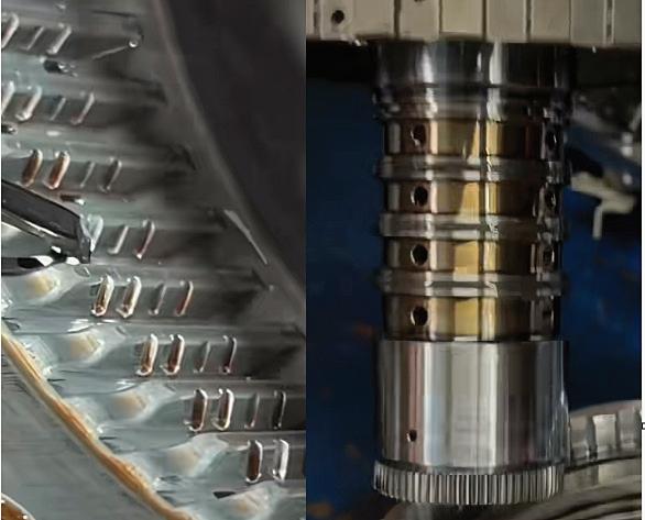
Understanding this type of connecting rod construction and tips on servicing
Mike Mavrigian
28 Diagnosing GM and Ford 10-Speed Transmissions
Why precision, fluid control, and diagnostic discipline matter more than ever
Jeff Taylor
40 Navigating Customer Communication in the DIY Automotive Era
A new era of informed—and sometimes misinformed—customers demands shops adopt transparent, collaborative communication strategies
Noah Nelson
44 Cleaning Up the Air
Why I invited the Environmental Protection Agency into my shop— and why it should matter to you
Craig Van Batenburg
TOOLBOX
55 Automotive Product Guide
56 Ad Index
58 Technical Service Bulletins
Media provides certain customer contact data (such as customers’ names,
and other opportunities that may be of interest to you. If you do not want Endeavor Business Media to
information available to third parties for marketing purposes, simply call toll-free 877382-9187 or email MotorAge@omeda.com and a customer service representative will assist you in removing your name from Endeavor Business Media’s lists. Motor Age does not verify any claims or
omissions
ONLINE
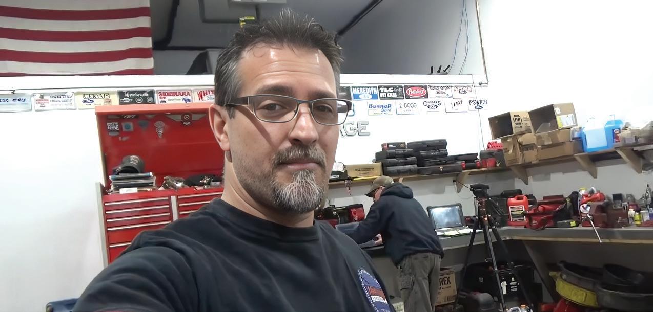
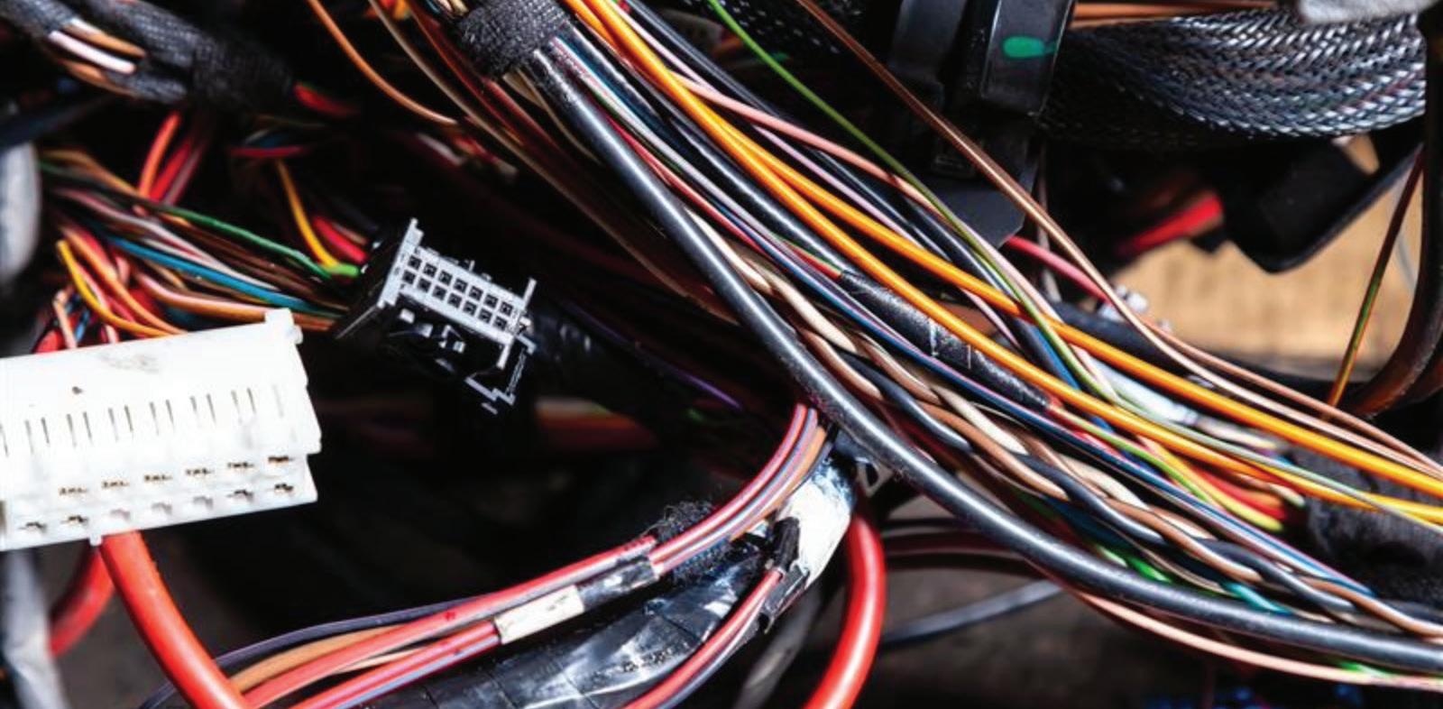
VIDEO MASTERING DIAGNOSTICS NO. 32: CAPTURING INTERMITTENT PARASITIC DRAINS WITH A LAB SCOPE
Motor Age’s Brandon Steckler takes on one of the most frustrating challenges in modern automotive diagnostics: intermittent parasitic battery drains. When a vehicle arrives with a dead battery but shows no measurable drain using traditional testing, layered vehicle networks are often to blame. Modern CAN systems operate at varying speeds—high-speed for mission-critical systems like ADAS, medium-speed for comfort and security features. Rather than relying on static current measurements, Steckler leverages the Pico 4425 to capture network activity over time. By analyzing intermittent wake-up events, technicians can correlate network disturbances to battery drain and pinpoint the root cause with confidence.

VIDEO SOLVING THE ‘EVER SINCE’ COMEBACK BEFORE IT STARTS
In this Motor Age Tech Tip, Pete Meier tackles a challenge every shop knows well: the “ever since” customer.
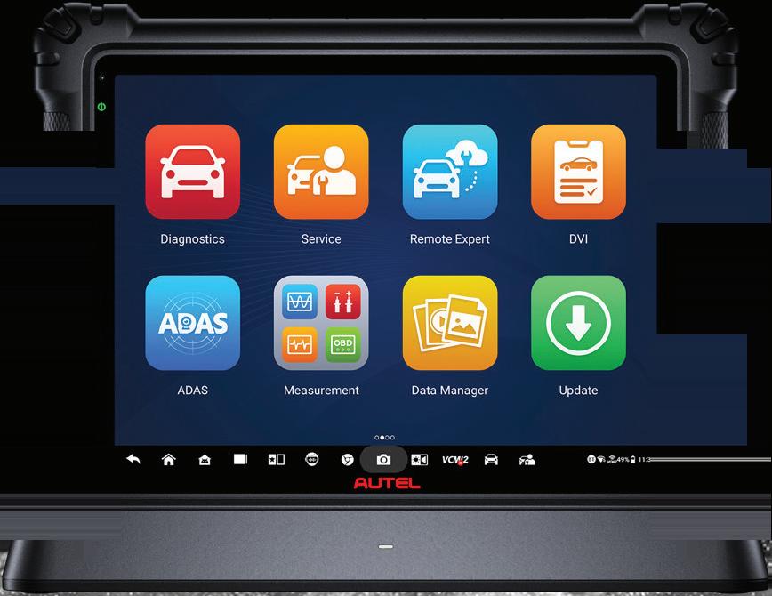
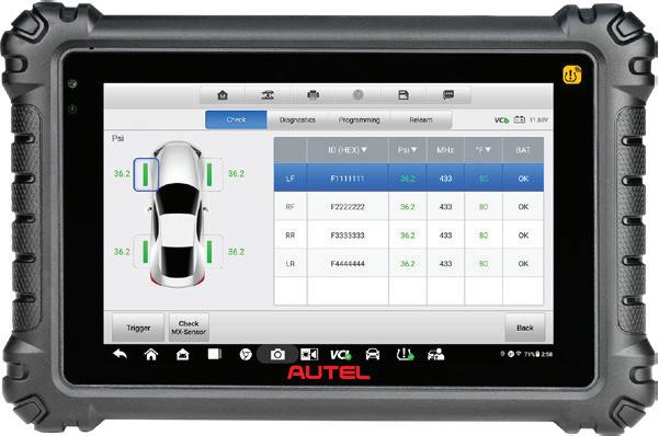
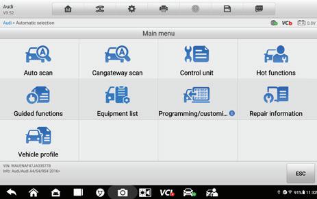
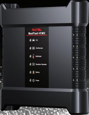
The “ever since” customer—a radio that doesn’t work, or a new noise appearing days after service—can quickly become a liability issue. Meier demonstrates how digital vehicle inspection best practices protect technicians and shop owners. Using the Autel MaxiSYS Ultra S2, he documents pre-existing vehicle damage during intake with photos, annotations, and shareable 3D reports. Combined with battery charging system testing and a full system scan DTC report, this comprehensive vehicle health assessment strengthens liability protection while building customer transparency and trust.
EDITORIAL
GROUP EDITORIAL DIRECTOR
Chris Jones / christopherj@endeavorb2b.com
EDITOR
Mike Mavrigian / mmavrigian@endeavorb2b.com
TECHNICAL AND MULTIMEDIA CONTENT DIRECTOR
Erik Screeden / escreeden@endeavorb2b.com
TECHNICAL EDITOR
Noah Nelson / nnelson@endeavorb2b.com
CONTRIBUTING WRITERS
Jeff Taylor, Craig Van Batenburg, Brandon Steckler
ART AND PRODUCTION
ART DIRECTOR
Emme Osmonson
PRODUCTION MANAGER
Sheila Ward
AD SERVICES MANAGER
Karen Runion
SALES
ASSOCIATE SALES DIRECTOR
Mattie Gorman-Greuel / mgorman@endeavorb2b.com
DIRECTOR OF BUSINESS DEVELOPMENT
Cortni Jones / cjones@endeavorb2b.com
ACCOUNT EXECUTIVES
Kyle Shaw / kshaw@endeavorb2b.com
Marianne Dyal / mdyal@endeavorb2b.com
Darrell Bruggink / dbruggink@endeavorb2b.com
Sean Thornton / sthornton@endeavorb2b.com
Diane Johnston / djohnston@endeavorb2b.com
Lisa Mend / lmend@endeavorb2b.com
Chad Hjellming / chjellming@endeavorb2b.com
Austin Miller/ amiller@endeavorb2b.com
ENDEAVOR BUSINESS MEDIA, LLC
CEO
Chris Ferrell
COO
Patrick Rains
CDO
Jacquie Niemiec
CALO
Tracy Kane
CMO
Amanda Landsaw
EVP TRANSPORTATION
Chris Messer
EVP ENDEAVOR BUSINESS INTELLIGENCE
Paul Mattioli
VP OF CONTENT STRATEGY, TRANSPORTATION GROUP
Josh Fisher
BUSINESS STAFF
PUBLISHER
Andrew Johnson
BUSINESS DEVELOPMENT DIRECTOR,
MOTOR AGE TRAINING
Michael Willins
HOW TO REACH US
ENDEAVOR BUSINESS MEDIA LLC.
30 Burton Hills Blvd, Ste. 185, Nashville, TN 37215 Phone: 800-547-7377
CUSTOMER SERVICE
Subscription Customer Service 877-382-9187; 847-559-7598


MotorAge@omeda.com PO Box 3257 Northbrook, IL 60065-3257
REPRINT SERVICES reprints@endeavorb2b.com
MEMBER OF:

SCAN TO WATCH THE VIDEO
SCAN TO WATCH THE VIDEO










Diagnostics Are Critical, But So Is Proper Installation
All service technicians deserve recognition and respect for their skilled contributions to shop success
TRACKING A PROBLEM
THAT INVOLVES COMPLEX DIAGNOSTICS can be challenging, to say the least. The skilled technicians who can pinpoint the root cause of an otherwise “mysterious” concern are invaluable to any shop and deserve the appropriate accolades. Once the issue has been identified, the completion of the job is often turned over to a technician who might be considered a “parts changer” or “general service tech.”
The skill of the “parts changer” is nonetheless critical to the shop’s success. If the “parts replacement” isn’t performed correctly, all of the advanced skills of the diagnostician are for naught. Whether the required component replacement or system assembly is performed by the same specialized technician who performed the diagnosis or by a general service tech, the proper installation of a part is far from simple.
Essential Skills and Knowledge
The general service technician is tasked with skills including the proper use of precision measuring tools such as calipers, micrometers, and bore gauges; an understanding of fastener thread treatment and torque/torque-angle tightening; choosing the correct sealing material; an understanding of pistonto-valve clearances; how to reference and adhere to factory-specified clearances and tolerance ranges; choosing the correct tools for the job; and more.
Granted, some diagnostic techs also perform the repair, but in some shops, the diagnostic techs may specialize in problem-solving, while the repair task is then relegated to a general service tech. In that case, while the diagnostic tech may have identified the issue, it’s up to the service tech to carry out the mission.
During removal, inspection, and installation, specific procedures and often specialized tools or equipment are involved to successfully complete the job. The “parts changer” deals with disassembly and reassembly steps that often must be performed in a very specific manner. He or she must determine the best way to access the part(s) involved, which often requires removal of non-related components and/or harnesses. He or she must be well versed in tool selection, removal and installation techniques; the use of torque wrenches; angle tightening methods; skill in using and reading calipers, micrometers, and bore gauges; the knowledge required in reading and interpreting OE specifications; and much more.
Every aspect of service, no matter how “simple” it may seem, requires expert knowledge and skill. In this age of electronic system management, sometimes too little emphasis is placed on the critical role that “wrenching” plays in every aspect of service.
Respect Earned Through Excellence
Once the sometimes-difficult task of
diagnosing an issue is determined, the job isn’t complete. It’s not a matter of “well, the hard part is done. Now just replace the part.” The technician who performs the actual repair deserves the same level of respect and admiration as a highly-trained technician who might specialize in advanced electronic diagnosis. Respect is earned, not given. All techs who perform any phase of service in the shop deserve the same level of admiration as part of the team that makes the shop successful.



MIKE MAVRIGIAN MOTOR AGE // EDITOR mmavrigian@endeavorb2b.com
























Failed Roller Lifter
If you run into an engine that features a roller cam (virtually all V-6 or V-8 pushrod engines today) that has a ticking noise, the engine may idle smoothly, but as you rev the engine, the ticking noise becomes louder and louder, and gets into a misfire. You likely have a damaged roller lifter.
After using an ear scope to isolate the offending lifter, you remove the lifter only to find that one or more of the tiny needle bearings have left the roller axle, and the roller may (upon very close inspection) appear a bit distorted and may display damaged
Subaru Stays Alive
If the radio keeps playing and you see a dash message “Turn off engine before exiting” in a 2019 Subaru Outback, here’s a tip: If the ignition on a push-button start vehicle is turned off before the shifter is placed in the Park position, the ignition mode changes to ACC mode. When this happens, the radio stays on, and you see the message, even with the engine turned off, and the driver’s door is open. A similar condition can take place if there’s a problem with the park switch. This condition is easily fixed by starting the engine and shutting it back off again while the shifter is in the Park position.
edges. However, don’t assume that you can simply replace the bad lifter. Using a borescope, inspect the cam lobe. If you only have a view of the base circle, this can easily fool you into thinking that the lobe is fine. Turn the crank by hand and be sure to inspect the opening ramp and the lobe peak, where valve spring pressure is the greatest. That’s where you’ll find lobe damage. In short, a bad lifter can easily damage the cam. Be sure to closely inspect the cam. Otherwise, you’ll waste time by reinstalling the intake, injectors, etc., only to find that the tick is still there.
Dirty MAF
If a customer’s engine runs rough, and after checking with a scanner, you find DTC P0171 (system too lean Bank 1), and you monitor live data and find the mass airflow sensor signal parameter erratic, inspect the air intake system. If you at first find no faults, back-probe the MAF and monitor the sensor signal with a lab scope. If the sensor signal is erratic with a key on/engine off, use a multimeter to check for the presence of voltage and ground. If both are present, you’ve narrowed it down. Remove the MAF and closely inspect it. You may find debris in the sensing element. Clean the MAF and reinstall. The concern will likely go away.
Wheel Stud Replacement
When replacing a wheel stud from a hub, use a manual press tool to remove the old stud, instead of striking it with a hammer, which can result in hub flange warpage. When installing the new stud, do not thread on a nut and try to pull the stud to engage the splines using an impact wrench, as this can stress the stud and potentially damage the splines. Insert the stud from the backside of the hub, initially engaging the splines. Install a thick washer followed by a spare wheel nut of the proper thread size, and draw the stud fully using a hand wrench, while holding the hub stationary with a brass or aluminum bar across two of the other wheel studs. Tighten until the stud head is fully seated flush against its seat on the rear of the hub flange. Use a spare nut of the appropriate size to avoid marring one of the customer’s nuts.
Check the Mounts
If you have a rough-running engine and find no faults during diagnosis, check the engine mounts. A visual inspection may not be enough. Check the engine mounts for play using a prybar. You may find excessive play due to a damaged engine mount.

SCAN TO READ MORE ARTICLES LIKE THIS
Are the Heads Really Clean?
Just a reminder when dealing with rebuilt/restored or even new cylinder heads. If the heads have been glass bead cleaned at any point, never assume that all bead particles have been removed, even after a jet wash. It is possible that moisture in hidden pockets or passages may be holding clumps of blast media (or metallic particles trapped after machining). Regardless of a rebuilder claiming that the heads are “ready to go,” make sure you double-check and perform

a detailed cleaning with compressed air and the appropriate probe tools. To start, clean an area of your workbench and cover the bench area with a clean paper or towels, and tap the heads onto the workbench to see if any debris falls out (try short-drop slamming the head against the workbench with the deck contacting the bench). Use a probe light to check all passages. The point is to make absolutely certain that there is no debris trapped in the head.
Hubcentric Adapters
Whenever you’re dealing with a customer’s vehicle that has aftermarket aluminum wheels, pay attention when you remove the wheels. Some aftermarket wheels have larger hub holes than the vehicle’s hubs need, because the wheel maker may have made that wheel with a larger hub hole in order to fit a wide variety of vehicles. In order to properly fit the vehicle hubcentricaly (where the hub hole centers the wheel instead of relying on the wheel studs), if the wheel’s hub hole is too big for a snug fit to the hub, a plastic or aluminum hubcentric ring will be placed either on the hub or on the wheel. If a hubcentric adapter is in place, make sure it isn’t stuck
to the hub. The ring may be stuck to the wheel itself. If the ring is stuck onto the hub and not removed before installing another wheel or a spare wheel/tire, and the adapter stays in place on the hub, the replacement wheel will try to crush against the adapter, preventing the wheel from seating fully on the hub. The result will be a stressed wheel and lateral runout. Pay attention to see if a hub adapter is present. With age, rust and/ or dirt, the adapter may not be immediately visible. If you find hub adapters, remove them, clean the hubs and adapters, and apply a thin film of high temperature grease onto the adapters before reinstalling them.





Dissection and Leveraging of the Wiring Diagram
Your wiring diagram is the diagnostic roadmap—learn to read it to increase speed, reduce time, and cut costs
BY BRANDON STECKLER

PHOTO BY ALEKSANDR KONDRATOV
AS MY CAREER SHIFTED from a path of “just getting by” to one with a sense of direction, I’ve become proactive about not only referencing wiring diagrams sooner in my game plan but also using a lot more of what each one has to offer.
The 30,000-Foot View
Regarding the design of the automotive subsystems on today’s vehicles, assuming how something is designed to function isn’t wise. It’s far more prudent to assume that every subsystem differs in design from the one you last addressed.
In my experience, the old adage “There is more than one way to skin a cat” truly applies when it comes to system topology and circuit design. Referring to a wiring diagram to see how a circuit or system is configured is like learning all the players on a sports team and the job each of those players has. For instance, consider the functionality of a basic horn circuit. Realizing this difference in topology before troubleshooting begins will play a crucial role in an efficient diagnosis. Let’s compare what I would call a classic (or common) design to one from even as far back as 20 years ago (Figure 1).
The topology of the horn circuit from the 1996 GM vehicle is simple in design, and something many of us older (I mean, experienced) technicians are very familiar with. Most vehicles of this era possessed horn circuits of this design.
Depressing either of the two horn buttons on the steering wheel simply provided a ground path for the horn relay coil. With the buttons depressed, the horn relay coil became a magnet, and the contacts closed, allowing current to flow from the fuse box and through both horns (which were provided with a case ground where they fastened to the vehicle).
However, the story is very different from the 2006 Dodge. Unlike the GM, the Dodge’s horn button didn’t control the relay. It simply created a ground path for a horn-request signal that was output by the cluster. What can’t be seen here is
that the cluster (along with many other ECUs) resides on a bus network.
The grounding of the horn request signal initiated a horn request message on the bus from the cluster and was shared with the Integrated Power Module (or IPM, where the horn relay lives). Another ECU that resides within the IPM is in direct control of the horn relay. After that, the horn circuit behaves just like the GM circuit discussed above. As you can see, assuming “business as usual” could certainly lead to a long, expensive, and unprofitable day.
It’s in the Job Description
Combining what was just learned about system topology with the system’s de -
scription and operation will allow for a play-by-play breakdown of the system’s functionality. Having this data will allow you to determine a game plan for how to approach a system fault. For instance, reading about the system description and operation for the Dodge’s horn circuit educated me to the fact that ECUs communicated on a bus network. With this powerful knowledge, my first step in analysis would be to leverage a scan tool (Figure 2).
With a capable scan tool in hand, I could use it to determine where a fault may lie if the horn-request message hadn’t made it to its destination: • Did the cluster see the horn-request signal being manipulated?
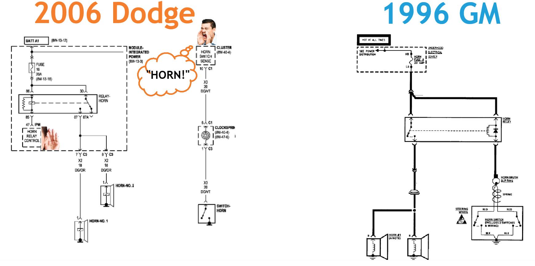
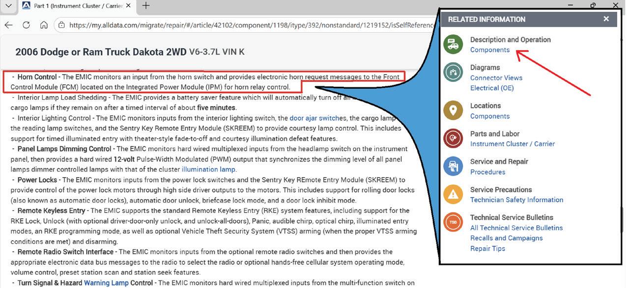
FIGURE 1: Determining system topology should always be an early step in the diagnostic process. Look how differently both of these systems are configured.
PHOTO BY BRANDON STECKLER
FIGURE 2: System description and operation allow you to have an anticipation of how a system is designed to work. If you understand how it works, you can easily diagnose it when it isn’t working.
PHOTO BY BRANDON STECKLER
• Did the IPM receive the command from the cluster?
• Did the IPM attempt to energize the horn relay?
These three simple (but important) questions could be asked right from the driver’s seat. In fact, you wouldn’t even have to open the hood, and you would already have determined where not to waste any time testing.
Again, all of that could be derived simply by looking at the wiring diagram and the system’s description and operation. Taking it a step further, though—by way of bi-directional control—the horn relay could be manipulated. What does this do for us? Well, let’s break that down a step further.
If the horn failed to operate using the horn pad but successfully sounded when commanding the relay to operate with the scan tool, you would’ve proven several things: The horn functions, so adequate voltage supply, ground supply, and horn integrity can be taken right off the table.
The IPM (ECU under the hood/intelligent fuse box) is alive and well. It’s capable of receiving/processing message requests and executing the output (driving the horn relay). Ultimately, the fault had been isolated to an input issue, simply by process of elimination and leveraging a little logic from what was learned above. As can be seen, this isn’t difficult—it just takes some discipline.
Talking the Talk
As mentioned several times above, this horn system leverages the CAN bus to carry the horn request and command between ECUs. But how would we learn which ECUs are in place within this configuration and the media in which these messages are carried? That’s where the information bus details come into play. These diagrams contain only the information pertinent to how ECUs share information. All of the particular circuits regarding component functionality and
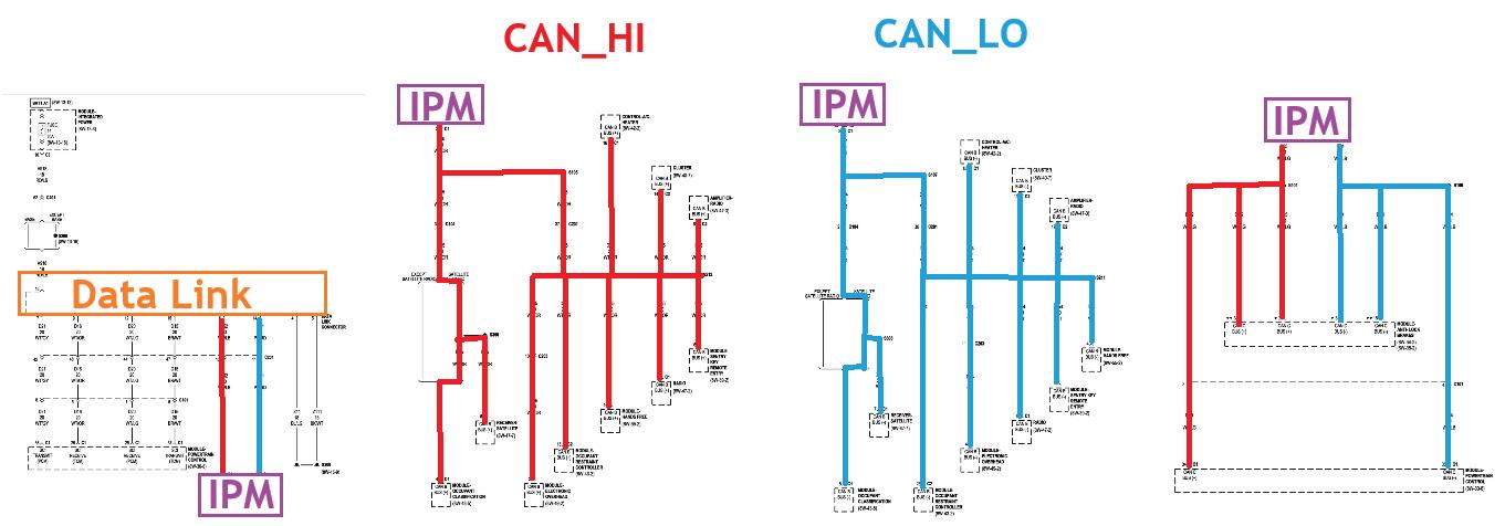
PHOTO BY BRANDON
CONTRIBUTED
CONTRIBUTED

FIGURE 3: Information bus details allow you to coordinate a plane of attack when communication issues exist between nodes.
STECKLER
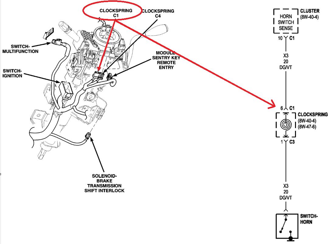
FIGURE 4: Knowing where to test comes from knowing what is most efficiently accessed. Referencing component locations makes light work of that task and saves a boatload of time.
GRAPHIC
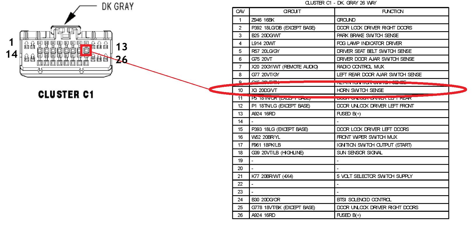
FIGURE 5: Connector view offers details about each connector and ensures you positively identify the circuit you intend to test. It is the difference between a proper and botched diagnosis.
GRAPHIC









power/ground distribution have been intentionally eliminated from the diagrams to allow a technician to focus on the communications networks only (Figure 3).
For instance, the diagrams will show:
• In-line connectors
• Harness-to-harness connectivity
• Splices and star connectors
• Gateways
Each network (Hi-speed CAN, Medspeed CAN, LIN, Ethernet, K-line, MOST, etc.) Having access to this information will help you strategize (on paper, at your toolbox) before approaching the vehicle. This is important because many of these networks can be found throughout the entire vehicle, including under the carpet, within door panels, inside tailgates, above the headliner, behind the dashboard, under the vehicle, and inside the engine compartment.
The labor cost alone of simply eliminating suspect components from the network (arbitrarily) could be thousands of dollars and take weeks of work. Bypassing ECUs with jumper wires and 120-ohm resistors is a much better way to eliminate potentially faulted sections of media or even faulted ECUs—strategically. And none of this would be possible without implementing the information bus diagrams.
Best Course of Action
So, it’s now time to move forward with confidence. You’ve leveraged the previous wiring diagram features and characteristics to give you a logical sense of direction, and now you have a decision to make on where to conduct the testing. When faced with that question, my answer is always the same: I’ll conduct testing at the easiest component to access. And the section of service information containing “component location” is the next stop for me.
For the sake of discussion regarding our Dodge horn system, say, for instance, that the scan tool indicated no loss of communication; yet the horn failed to
sound, and the cluster did not report a request for horn operation. Logic should dictate that the input circuit is somehow compromised. We have a choice to make:
• Remove the steering wheel to test for presence of horn request signal voltage
• Remove cluster to test for presence of horn request signal voltage
• Locate another access point requiring no disassembly
By visiting the component location section of service information and combining it with the wiring diagram details for the horn input circuit, we can devise a plan to test without disassembly. More specifically, we can determine if the signal is present from the cluster (where it originates) and if so, can the signal be manipulated (pulled low) when the horn pad is depressed. The answers to these questions determine the next logical course of action, and the best part is that no time was wasted—just invested (Figure 4)
If the signal is present at connector C1-Terminal No. 6, it should get pulled low with the horn depressed. If not, test at connector C3-Terminal No. 1 during the same conditions. If the signal still fails to pull low, an open circuit is present between C3-1 and the horn switch. But “notso-fast”—take a moment to create your own path to ground. Become the horn switch and short the horn request signal to ground. Not only will this confirm you are on the right path (fault located closer to the steering wheel), but when the horn sounds, you’ve also confirmed the functionality of the entire horn system (nothing more embarrassing than discovering multiple faults in the same system after a repair or correction has taken place).
Pinpoint Location
As you progress toward a pinpointed diagnosis, many times you will find yourself at a relatively large ECU connector, an in-line connector, or one that interfaces a fuse box. In many of those situations, the connector can have as many
as 120 terminals. It’s easy for your eyes to deceive you, but at the same time, it’s of the utmost importance to identify the correct circuit before testing. This is the difference between a correct or botched diagnosis, and it’s absolutely your responsibility as a diagnostician. The connector view will offer information like:
• Connector body color
• Number of terminals
• Connector layout
• Terminal position
• Color of the wires in each terminal
• Circuit function
While using this information from the wiring diagram, I will identify several wires (by way of color) adjacent to the terminal I’m interested in. This acts as a bit of an insurance policy (or a checks-andbalances system) to help ensure I’m seeking the correct wire terminal (Figure 5).
For instance, the horn sense switch circuit we’ve been chasing is a darkgreen/violet wire and should be located between both a violet/tan wire and a tan/ orange wire.
Furthermore, I will find this wire located on the top row of the connector (in reference to the connector position assurance tab), on the end with the three smaller terminals (not the end with the two smaller terminals). I just described four factors of identification to ensure a mistake isn’t made. This is how to remain accurate and efficient at the same time.
Flow Charts: More Than Just Toilet Paper
There’s been an ongoing joke circulating the diagnostic world that flow charts are only good for toilet paper. Where that joke stemmed from is that relying on flowcharts to solve symptoms doesn’t always end well. However, from my perspective, they do have value to offer.
Flow charts tend to contain some goodies that I leverage when available. Helpful information can be found in them to better understand the system you’re addressing and why it may not be behaving as expected. Some of these include:
• Resistance specifications
• Voltage level thresholds
• Expected reactions
• Default strategies
• Expected values at test points
• Testing conditions/running conditions
• Function criteria
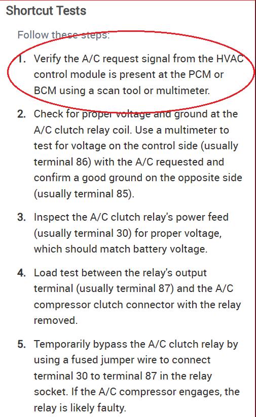
Information like that above helps recreate scenarios where expected values can be tested for. For instance, there would be no use in testing for an A/C compressor function with the ignition key in the “off” position if part of the function criteria states the key must be in “Run.”
I also leverage flow charts to quiz myself on my knowledge of system functionality. Many times, my understanding of how a circuit or system functions is a misconception. The information found in flow charts can help set the record straight.
To sum it all up, not any single one of these information sources is better than the other. It takes an understanding of what each one can do for you in the situation you are encountering at the time.
Take the time to research all the data that is valuable to you and implement it. In only a short period of time, you’ll find your path to diagnostic success has been shortened as well!

BRANDON STECKLER is an ASE Master Technician (A1-A9, C1, and advanced level designations in L1, L2, L3, L4, and xEV-Level 2) and a certified instructor with expertise in automotive diagnostics and driveability. He earned GM Automotive Service Education credentials from Northampton County Community College. With more than 20 years of experience spanning dealerships and independent shops, he instructs at Carquest Technical Institute and Worldpac Training Institute, authors books and classes, and provides technical support through Steckler Automotive Technical Services.

Clarifying the Difference: Module Flashing, Coding, and Adaptation Procedures
Know which electronic procedure to perform and when to avoid costly misdiagnosis
BY ERIK SCREEDEN
OFTEN, THE FIRST SIGN OF TROUBLE comes when all signs point to a programming event being “successful,” yet the vehicle won’t communicate, won’t shift correctly, or the dash lights up like a Christmas tree. At that point, the assumptions tend to be along the lines of a failed flash or a defective module. But often, the real issues are simpler: the correct electronic procedure was never performed in the first place. These days, vehicles don’t rely on a single post-repair step. Often, it’s a sequence of distinct processes that are too frequently misunderstood. Before deciding how to fix a module-related problem, technicians must first understand what the vehicle is asking for—and that starts with using the correct terminology.
Why Terminology Matters in Modern Diagnostics
In today’s service environment, electronic service procedures are no longer limited
PHOTO BY SCHARFSINN
to engine control modules or drivability complaints. Body controllers, steering systems, climate control modules, ADAS components, and even door modules now require post-repair electronic interaction. Yet despite the growing reliance on these procedures, the terminology used to describe them has become increasingly vague, and in many cases, misleading.
“Programming” has become one of the most overused words in modern diagnostics, and I am as guilty of it as anyone. OEM service information, scan tool menus, training materials, and even parts suppliers frequently use it as a catch-all term to describe everything from a software update to a simple throttle relearn. While that may seem harmless, it creates a real problem at the street level. Technicians often perform the wrong procedure because they were given the wrong label.
A module that needs coding may accept a flash but still fail to communicate properly. A vehicle that only requires adaptations may be subjected to an unnecessary software update. In both cases, the result can look the same: warning lights, fault codes, and a growing suspicion that something went wrong during “programming.” The technician is then forced into additional diagnostics that would not have been necessary.
Correct terminology matters because each electronic procedure serves a different function, carries different risks, and requires different tooling and procedures. Understanding the distinction between flashing, coding, and adaptation is imperative. As vehicles continue to rely on networked control modules to function as a system, knowing exactly what each module needs and when is the key to accurate, efficient, and profitable repairs.
Module Flashing: Replacing the Software
Module flashing is the most commonly referenced and most misunderstood electronic service procedure performed on modern vehicles. Flashing is simply a software replacement process. The existing
operating software inside a control module is erased and replaced with a newer or different version supplied by the OEM. This is not a configuration change or a learning process; it’s a rewrite of how the module operates.
OEMs typically require flashing to address known software defects, emissions compliance updates, network communication issues, or strategy improvements documented through Technical Service Bulletins. In some cases, flashing is mandatory following module replacement, specifically when a new control unit is delivered without any operating software installed. In these situations, the module is unable to perform its job until the flash process is completed.
What flashing does not do is just as important as what it does. Flashing does not tell the module what vehicle it’s installed in, what options the vehicle has, or how the system should adapt to real-world conditions. A module can be successfully flashed and still be incapable of communicating correctly on the network or performing its intended function. This is often where technicians mistakenly assume a flash failure, when in reality the module simply has not been coded
or adapted yet.
Because flashing replaces essential software, it carries the highest level of risk among electronic service procedures. A stable power supply during the programming process is imperative, as voltage drops or interruptions during the process can corrupt the module and render it inoperable. Internet connectivity and subscription access are equally critical. Unlike adaptation procedures, flashing cannot typically be “undone” by clearing faults or cycling the key.
Tool selection also plays a major role. While many aftermarket scan tools support flashing through pass-thru programming using a J2534-compliant Vehicle Communication Interface, aftermarket options can be tricky to set up and use. The way OEM software interfaces with aftermarket tools and their drivers can sometimes be a challenge to navigate. OEM tooling can offer a smoother process, but can pose a significant financial investment on the side of the shop or technician. Often, the difference between the OEM VCI and aftermarket options are only some drivers and configurations, with their hardware being virtually identical.
Flashing can be an effective fix when
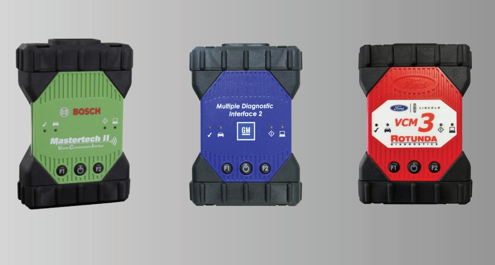
PHOTO BY ERIK SCREEDEN
the problem truly lives in the software, but it’s not a cure-all. Too often, a vehicle ends up flashed simply because it has an electronic fault, not because the flash is actually required. Service information and TSBs can help with this, and that’s another reason why referencing these materials is vital. Knowing when a software update is necessary and when it’s just one piece of a larger post-repair process is what separates efficient electronic diagnosis from expensive trial and error.
Coding: Telling the Module What Vehicle It Is In
If flashing is about what the module knows how to do, coding is about what the module is allowed to do. Coding defines how a control module is configured to operate within a specific vehicle. This includes identifying the engine, transmission, body style, market region, and optional equipment. Without correct coding, a module may power up and communicate, yet still fail to function correctly.
Coding is most commonly required when installing a replacement module. Many new and remanufactured modules
are delivered in a default state with no vehicle-specific configuration stored. Until that information is written, the module has no way of knowing whether it belongs in a base model or a fully optioned vehicle. The result can be missing features, inoperative systems, or network faults that look like hardware failures.
European platforms are where technicians most often encounter explicit coding procedures, but the concept isn’t limited to European vehicles. Domestic and Asian manufacturers also rely on configuration data, even if the process is handled automatically in the background. VIN-based coding, as-built data, and centralized configuration files all serve the same purpose: they ensure each module behaves correctly within the vehicle network.
Coding is frequently confused with flashing because both procedures are often performed during module replacement. The difference is that flashing installs the software, while coding personalizes that software to the vehicle. A module can be flashed with the correct calibration and still refuse to communicate properly if it hasn’t been coded. In those
cases, the flash may complete successfully, but the repair isn’t finished. Incorrect coding carries its own risks. Selecting the wrong options can disable systems, trigger communication faults, or create problems that only appear during certain driving conditions. Some platforms allow coding changes to be reversed, while others permanently lock the configuration once written. This makes verifying vehicle equipment and service information key before starting the process.
From a tooling standpoint, coding access varies widely. OEM scan tools typically provide guided or automated coding routines. Advanced aftermarket tools may offer both automatic and manual options, especially on European platforms. Manual long coding can be effective, but it also demands a high level of system understanding. One incorrect selection can create significant heartburn for the technician who didn’t need to exist.
Adaptation Procedures: Teaching the Module How to Operate
Adaptation procedures are another piece that’s often overlooked after electronic repairs. While flashing installs software and coding configures the module to the vehicle, adaptations allow the module to learn how to operate under real-world conditions. These learned values help fine-tune system behavior based on component tolerances, wear, or driver input.
Adaptations are sometimes referred to as relearns, but that label doesn’t fully capture their importance. An adaptation is the process by which a control module establishes baseline values and adjusts its strategy so the system operates smoothly and with predictability. Without these learned values, a system may function but not function correctly.
Common adaptation procedures include throttle body and idle learn routines, transmission shift adapt resets, steering angle sensor calibration, HVAC door calibration, and brake or stability control calibrations. These procedures
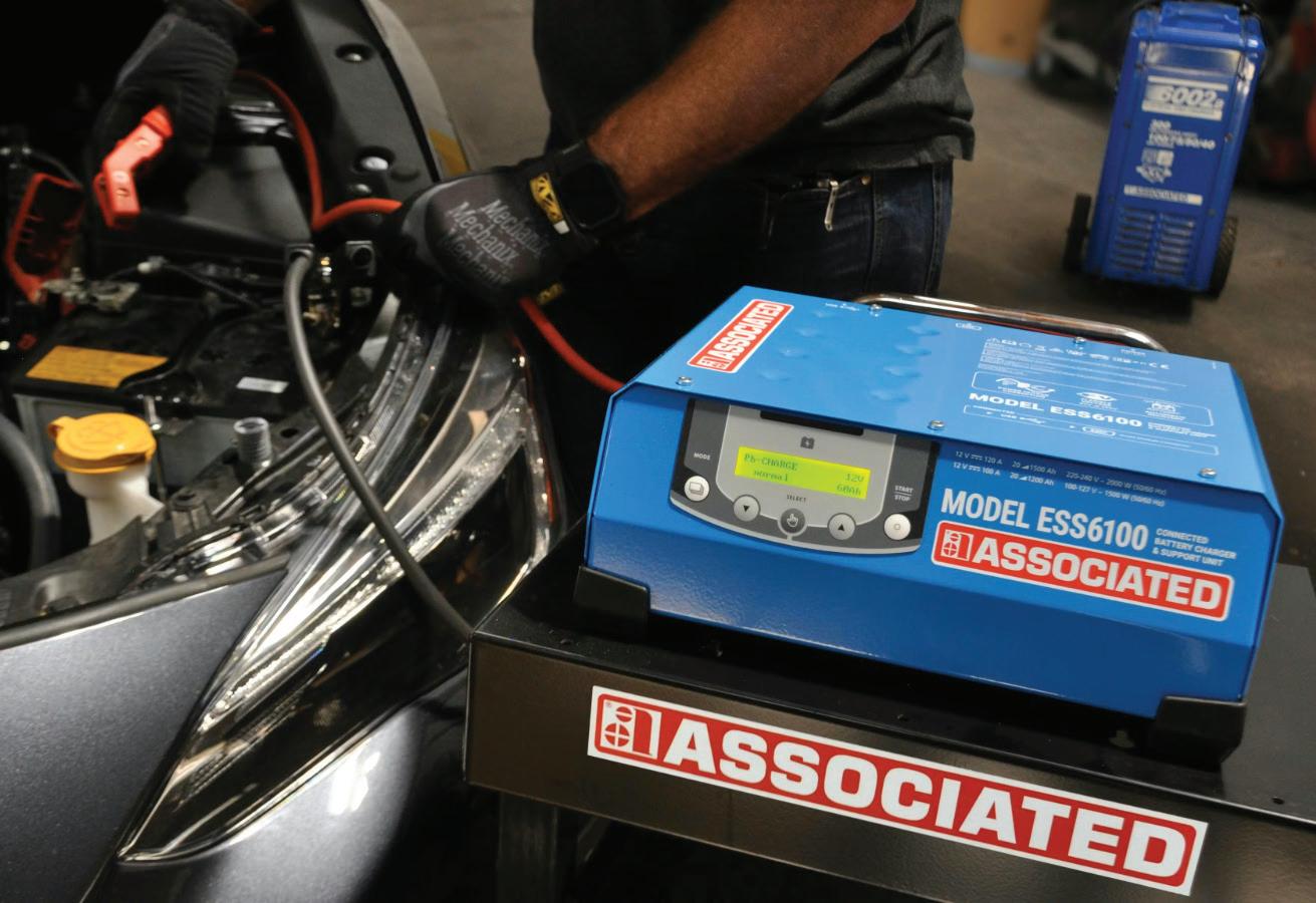
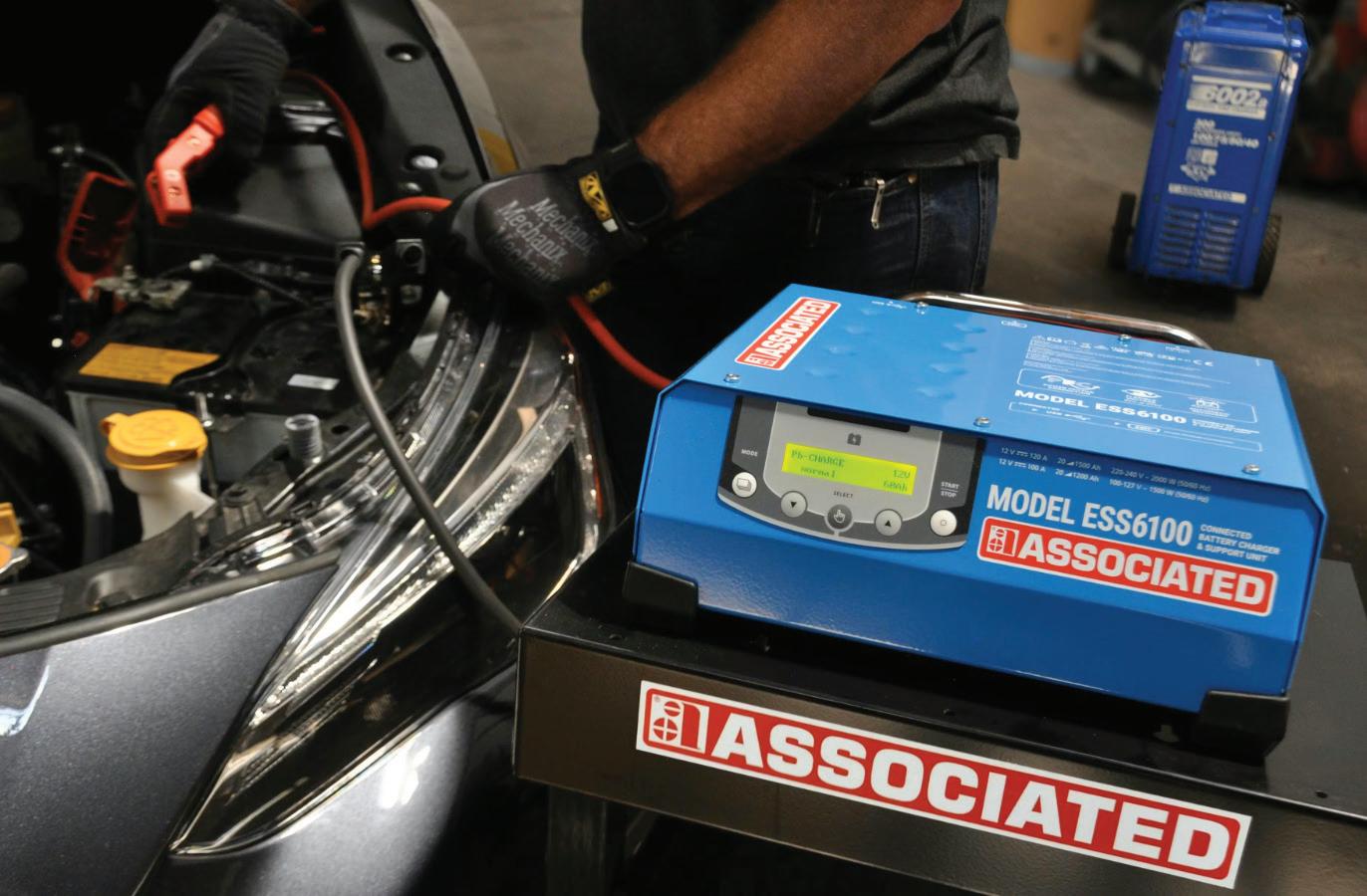
THE NEED to provide a vehicle with a consistent and clean supply of power during these types of procedures cannot be overstated.Modern vehicle systems represent a considerable electrical load on the vehicle’s battery, and a reduction of voltage to a module during critical phases can cause everything from a failed procedure to a bricked module.
PHOTO BY ASSOCIATED EQUIPMENT
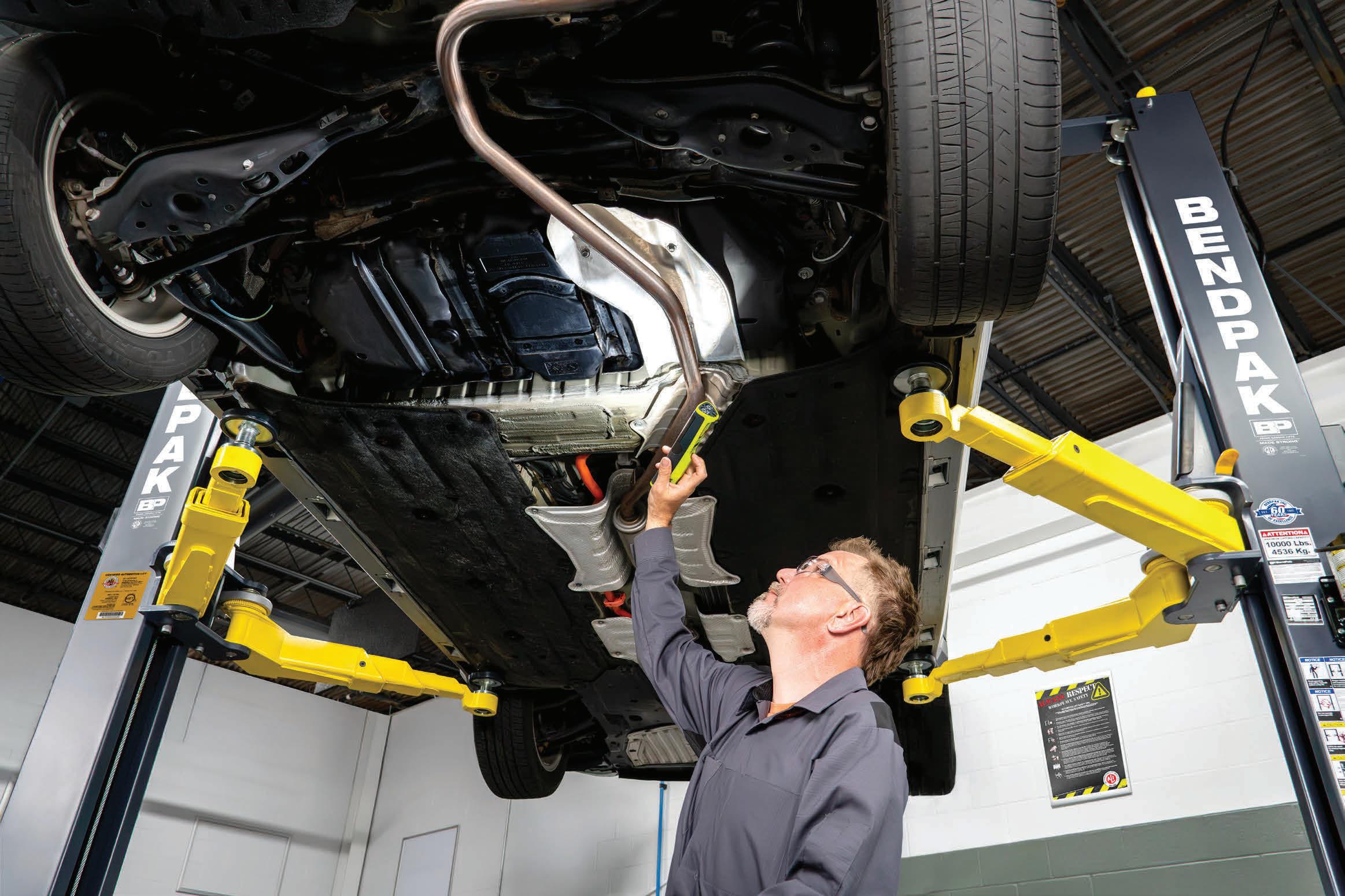
Every day, professionals and DIYers trust their lives to vehicle lifts. But the web is flooded with offshore resellers pushing uncertified, no-name lifts with bold claims — no proof, no oversight, no accountability.
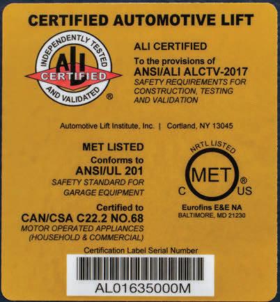
BendPak certified lifts meet ANSI/ALI ALCTV (current edition), the only nationally recognized lift safety and performance standard. Only certified lifts carry the ALI Gold Label and appear in the official ALI Directory, proof of third-party testing and validation.
At BendPak, safety is engineered into every lift. Built strong. Certified tough. And every Gold Label tells the story.
If you’re lifting cars and putting people under them, nothing matters more than safety. Don’t risk it on unverified imports. Get the lift that’s certified. Get BendPak.
Demand the Gold Label. Trust BendPak. Call 1-800-253-2363 or visit BendPak.com.
are often required after component replacement, battery disconnects, or module programming. In some cases, a flash or coding event will erase stored adaptations, making relearning mandatory before the vehicle is returned to service.
When adaptations are missing or incomplete, the symptoms can be misleading. Harsh or delayed shifts, unstable idle, poor throttle response, incorrect steering angle data, incorrect battery charging strategy, or inconsistent climate control
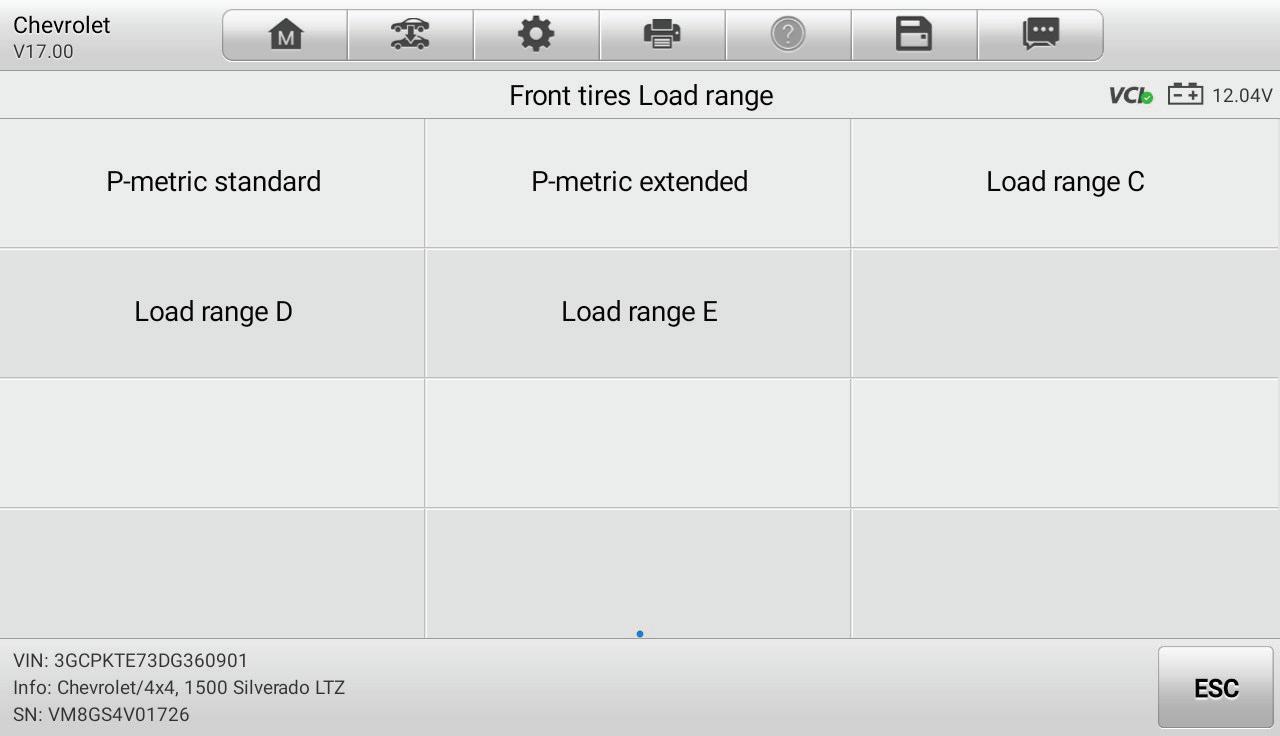
MANY POST-REPAIR procedures require module coding, and the Remote Control Door Lock Receiver replacement on the GMT900 is a prime example.GM uses the same module across multiple platforms, but tire load range variations exist, and accurate Tire Pressure Monitor (TPM) system operation is dependent upon accurate module coding. “Copy and paste” of TPM information is often the best option, but when not available, manually telling the module tire load range, and even tire size, may be required. Followed by a TPMS registration.
PHOTO BY ERIK SCREEDEN
operation are common complaints. Fault codes may be present, but just as often the vehicle sets no codes at all. This leads technicians to again chase problems that don’t exist.
Adaptations can be performed in several ways. Some require a scan tool-initiated routine that walks the technician through specific steps. Or, in some cases— like dynamic ADAS calibrations—they rely on precise drive cycles or operating conditions defined by the OEM. Temperature, vehicle speed, load, and time all matter. Skipping steps or rushing the process often results in adaptations that are not completed, even though the procedure appears to have been performed.
Tool capability is another important factor. Many aftermarket scan tools support common adaptation routines, but coverage isn’t absolute. Some OEMs restrict certain calibrations to factory-level tools or require online authorization. Knowing which adaptations are required and how they must be performed should be part of the technician’s repair plan. Adaptations allow a properly repaired system to operate as intended. Understanding the role adaptations play allows the technician to avoid unnecessary reprogramming, reduce comebacks, and deliver a more complete repair.
Post-Repair Electronic Workflow
Understanding flashing, coding, and adaptation as individual procedures is important, but repairs rarely involve just one step. Many electronic service jobs account for all three. Skipping a step or performing them out of order can cause the vehicle to leave the bay with unresolved issues.
Module replacement is an obvious example. A new control module may first require flashing so it contains the correct operating software. Once the software is installed, the module must be coded so it matches the vehicle configuration. Finally, adaptation procedures are needed to allow the system to learn baseline values and operate correctly. Completing only part













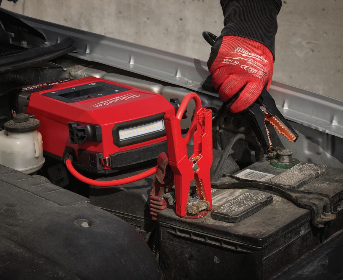
TRUE ALL-WEATHER PERFORMANCE ALWAYS READY TO JUMP LONGER LIFE JUMP STARTER















M18™ HOTSHOT ™ Jump Starter MWK-3841-20


Prepared to Jump in Under 70 Seconds
Performs at -4°F to 122 °F
Capacitors Rated up to 500,000 Cycles
Up to 70 Jump Starts with (1) M18™ XC5.0 Battery
Spark Proof, Reverse Polarity & Heat Protection
Custom Clamp Design to Ensure Secure Connection











of that process often will result in poor system performance.
Software updates follow a similar pattern. A module may be flashed to address a known concern, but that flash can reset stored configuration or learned values. If coding or adaptations are required afterward and not performed, the repair may appear unsuccessful.
Battery disconnects and power loss events can also often require attention. On some platforms, low-voltage or battery replacement can erase adaptations or trigger calibration requirements. Steering angle sensors, throttle bodies, transmission controls, and HVAC systems are frequent examples. Failing to read service information and have an understanding of system operation can easily lead to wasted diagnostic time.
Similar to your high school algebra class, order of operations matters. Flashing should be performed first when required, followed by coding, and then adaptations. Clearing faults and verifying system operation come last. It seems intuitive, but these steps occur out of order all the time.
The most effective way to avoid unnecessary programming is to slow down at the beginning. Reviewing OEM service information before thinking about connecting a tool will reveal exactly which steps are required and which aren’t. Not every electronic issue needs a flash, and not every repair triggers adaptation procedures. Knowing the difference allows technicians to work with a guided approach instead of guessing. A structured post-repair workflow creates a repeatable process. When technicians understand what the module needs and when it needs it, the repair becomes predictable, efficient, and far less risky.
Tooling Matters
Tool choice plays a major role in how successfully technicians perform flashing, coding, and adaptation procedures. While the industry often frames this as an OEM versus aftermarket debate, the real issue
is capability, coverage, and knowing your tooling limitations.
OEM scan tools and factory service platforms provide the most complete access to software, coding data, and guided procedures. They’re designed to work within the manufacturer’s environment, which means fewer unknowns during flashing and configuration. OEM tools also offer recovery options when something goes wrong, which can be critical when a module fails during programming. The downside is cost, subscription management, and the learning curve associated with multiple manufacturer interfaces.
Aftermarket tools have improved significantly in recent years and often handle everyday adaptation procedures quickly and efficiently. Many support pass-thru programming and can access OEM software through J2534 VCI interfaces. In the right situation, this approach is cost effective. The challenge is that diagnostic and bi-directional control coverage varies widely. Aftermarket tooling can often keep a technician covered, but keeping tooling on hand from multiple engineering groups allows the technician to hedge their bet when it comes to coverage.
Coding is where tool differences become most apparent. OEM tools typically provide automated or VIN-based coding that reduces guesswork. Aftermarket tools may offer both automatic and manual options, particularly on European platforms. Manual coding can be effective, but it assumes the technician understands the system well enough to verify every option. One incorrect selection can create problems that look unrelated to the original repair.
Adaptation procedures also vary by tool. Common routines are widely supported, but more specialized calibrations may require factory-level access or online authorization. Steering, brake, and ADAS-related adaptations are frequent examples.
The most successful shops don’t rely on a single tool to solve every problem.
Just as important, they train technicians to recognize when a tool limitation is the issue and when it’s time to change the approach. Many aftermarket scan diagnostic companies now offer virtual post-repair support and even diagnostic assistance. Using the J2534 capability of the tool, service technicians can remote into the tool and perform those procedures virtually. This can be a great way for a shop in the aftermarket to leverage these capabilities and keep work in-house without having to send a profitable repair down the road or bring in a hired gun to complete the repair.
Flashing, Coding, Adaptation: The Final Word on Post-Repair Success
Understanding the difference between flashing, coding, and adaptation is critical for technicians. Each procedure serves a distinct purpose: flashing updates the module software, coding configures it for the specific vehicle, and adaptations teach it to operate correctly in the real world. Neglecting to correctly complete the repair leads to unnecessary programming, misdiagnosis, and frustrated customers. By following a structured workflow, using the right tool for the job, and verifying each step, technicians can complete electronic service efficiently, confidently, and correctly the first time.

ERIK SCREEDEN serves as technical and multimedia content director for Motor Age. An ASE Master Technician with L1 and L4 credentials, he brings more than 25 years of industry experience. Screeden began his career as a Ford dealership technician, later working at independent repair facilities and a GM-specific performance shop. He transitioned to diagnostic and J2534 tool support before finally leveraging his expertise in technical sales.













Powder Metal Connecting Rods
Understanding this type of connecting rod construction and tips on servicing
BY MIKE MAVRIGIAN
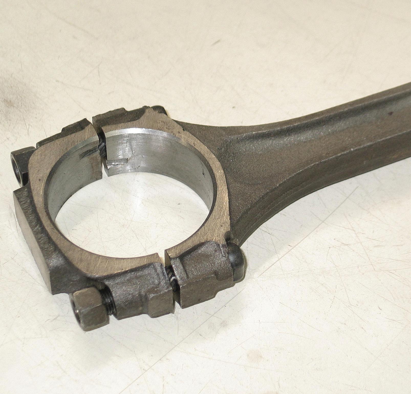
IT’S COMMONPLACE TODAY FOR OE MANUFACTURERS to use connecting rods of the powdered metal type. For example, all of the factory GM LS-platform engines feature PM rods, with the exception of the LS7 and LS9, which feature forged titanium rods.
Powder metal rods, also referred to

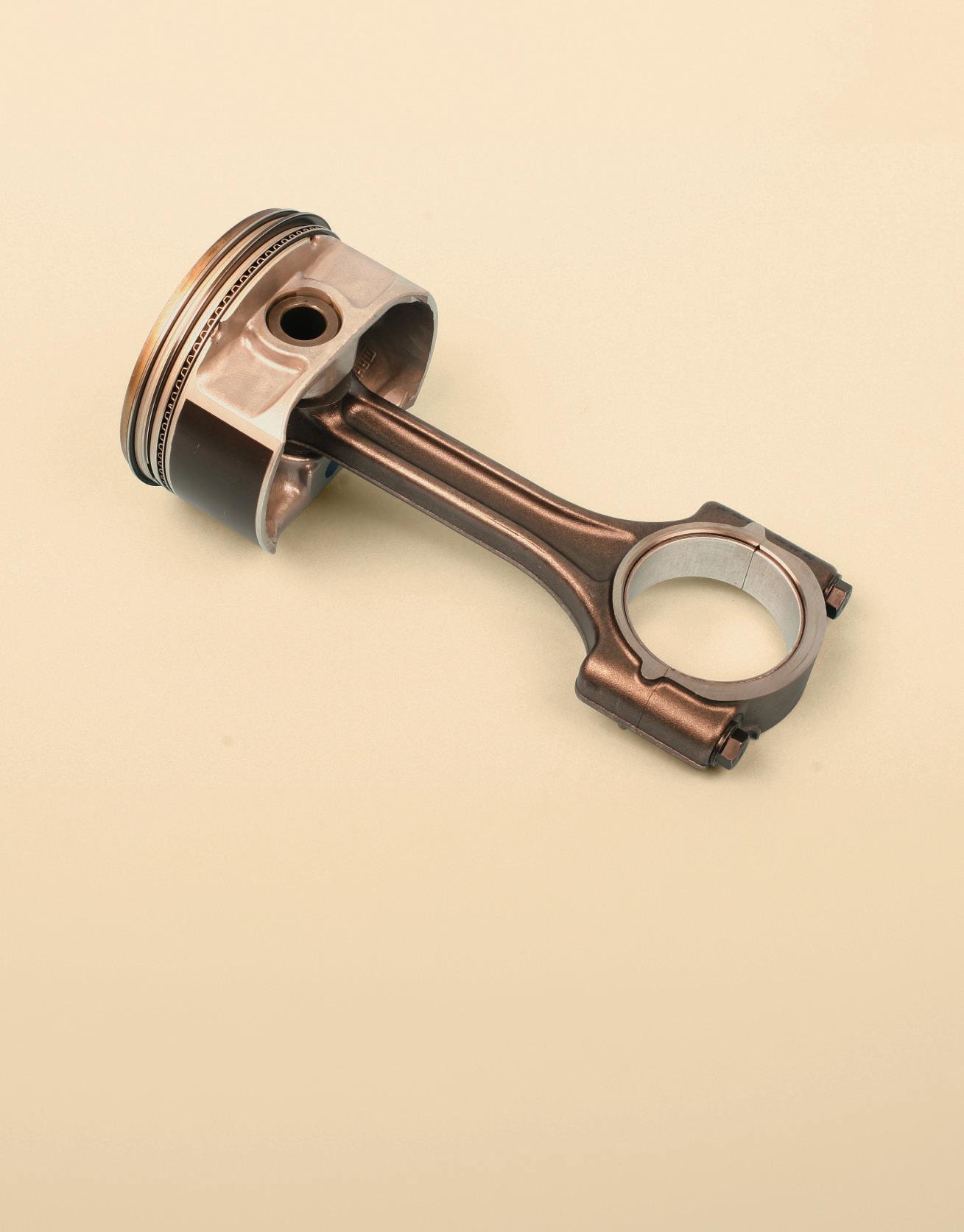
as “fractured cap” or “cracked cap” rods, differ in design and construction compared to cast or forged rods. Powdered metal rods are “pressure cast,” with a specially-formulated metal powder that’s placed into a mold, then heated to a melting point, and pressurized. Once out of the mold, the small and big ends are honed to size, and rod bolt threads are cut. The rod is then secured in a fixture at the rod’s big end and cap parting line area, and the cap is then snapped off, with no loss of material. The result is a fractured parting line on both the rod and cap. While this process may at first seem a bit crude, it creates a precise mating surface interlock. The cap fits the rod precisely (mirror image surfaces) for perfect capto-rod alignment. This mating design means each cap must always remain with its original rod. While a PM rod big-end bore can be slightly oversize, honed, and mated with oversize O.D. bearings, these rods cannot be resized in the traditional manner (where mat -
ing surfaces are ground flat to create a smaller, non-round bore, and then honed round again). Care must be taken when handling PM rods so as not to damage the irregular mating surfaces.
Why OEs Prefer Powder Forgings
The OEs are using powder forgings for a number of reasons. Tighter tolerances can be maintained in both dimensions and weight, and the use of a powder forging process makes connecting rods, which are easier to machine, require less stock material, and the process eliminates as many as six machining operations. According to MascoTech, a primary manufacturer of these rods for the OEs, the increased machinability of powder forging has reduced tooling per unit cost from about 22 cents to about 4 cents.
Design Advantages of Powder Metal Forging
• Even distribution of stress over the entire side of the I-beam area
CAST (shown here) or forged rods that feature machined-flat mating surfaces are easily reconditioned by removing a few thousandths of an inch from the rod’s big end and cap. This creates a non-round hole which is then honed to round to the required size. This isn’t the case with powder metal rods.
PHOTO BY MIKE MAVRIGIAN
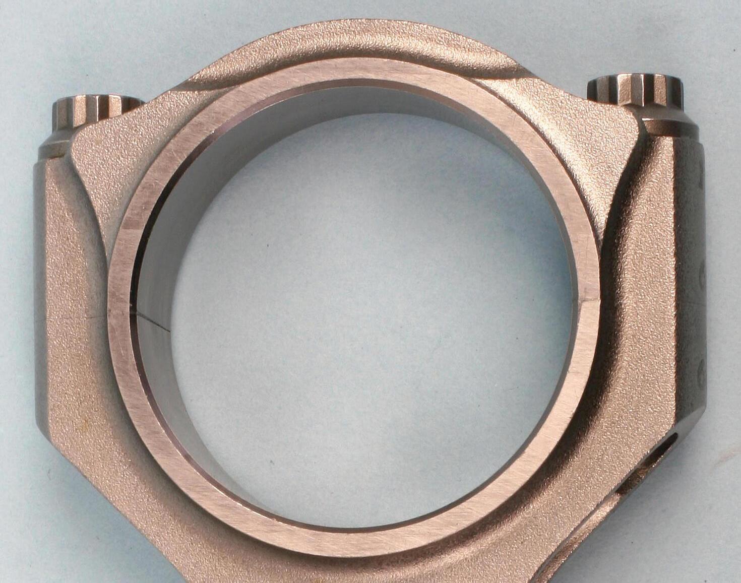
EXAMPLE OF a forged connecting rod. When the cap is torqued in place, the mating line is barely discernible. Cast or forged rods feature precisely machined flat mating surfaces.
PHOTO BY MIKE MAVRIGIAN
• Increased I-beam rigidity (100% increase in stiffness over conventional forged)
• Improved noise/vibration/harshness level, which improves piston and ring action
• No bore offset between rod and cap
• Increased bore stiffness and geometry
• Increased bearing reliability
• Reduced weight
• Crankshaft mass reduction
• Single weight grade (±2 g on 400g rod)
• Reduced mass variation for improved balance
• Full density across the entire rod
• Lower-cost carbon steel
• Proven fracture split method (no crank bore elongation during cracking)
• High machinability
Reconditioning PM Rods
A major concern when trying to recondition cracked cap rods in the traditional manner relates to the irregular mating surfaces of the rod and cap. When these rods are manufactured, they’re formed as a single piece. The caps are then separated by fracturing the cap from the rod, which leaves an irregular (and unique) mating surface. This irregular surface provides an ac -
curate location of the cap to the rod, preventing any misalignment of the cap during assembly.
However, if the mating surfaces are machined or ground flat to reduce the
rod’s large end bore in preparation for re-honing to size, you lose all centering ability. As described earlier, this would destroy the unique cap-to-rod interlock that was created when the
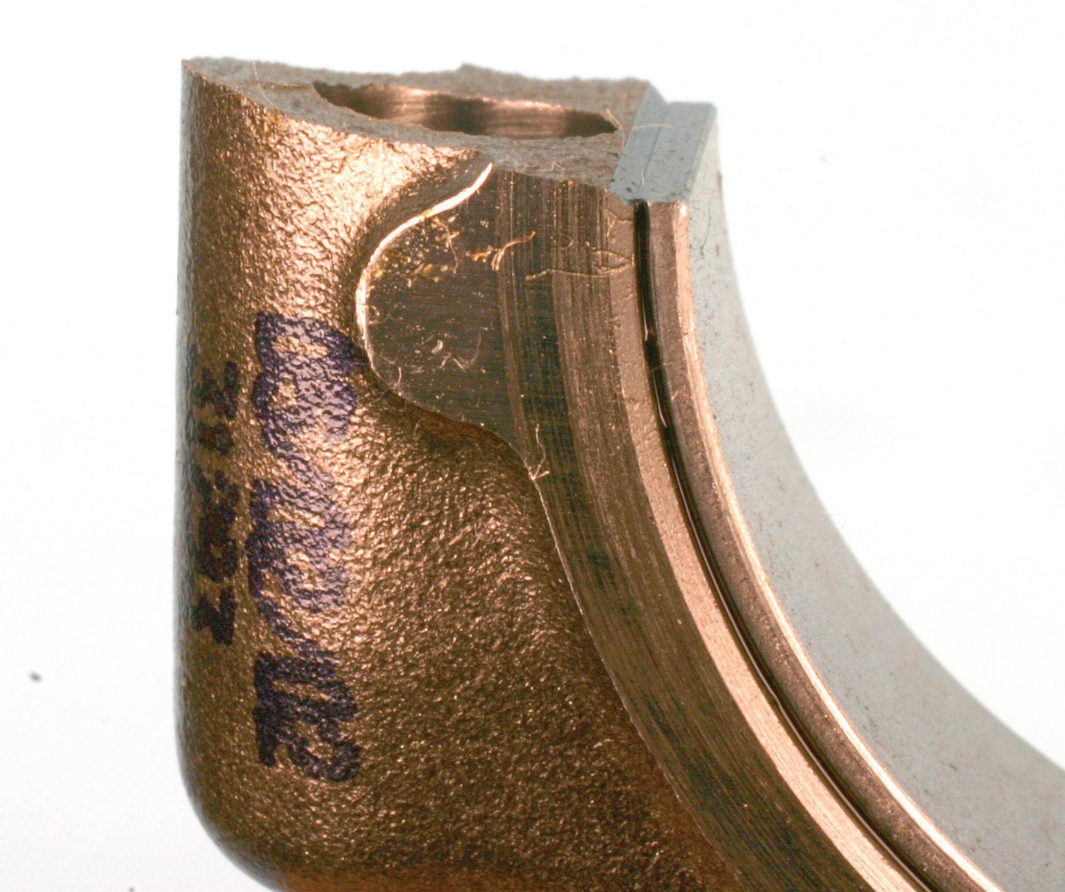
PHOTO BY MIKE MAVRIGIAN
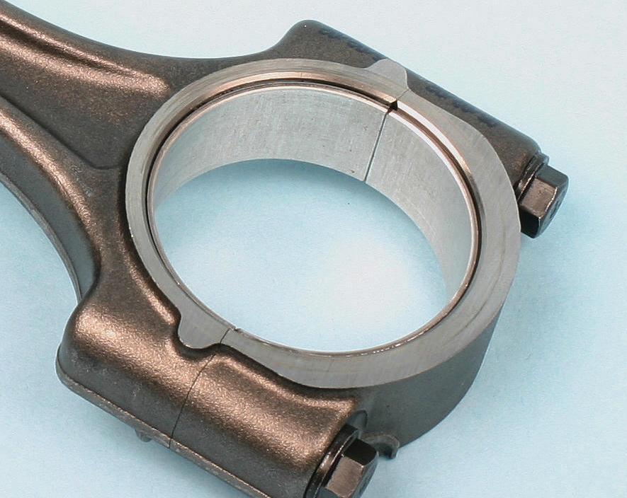
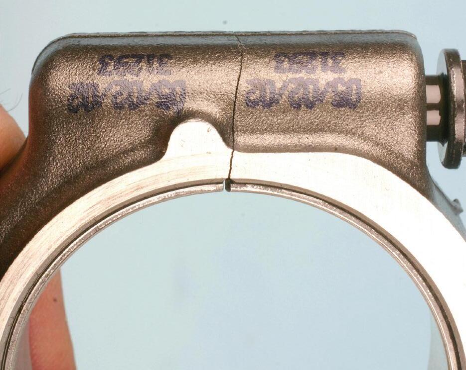
EXAMPLE OF a powder metal rod. Here, the rod bolts are not fully tightened. Notice the irregular mating joint. When fully tightened to spec, this line visually disappears.
PHOTO BY MIKE MAVRIGIAN
POWDER METAL rods are pressure molded as one piece. The caps are then separated by a controlled fracturing or “cracking” process, where the cap is snapped off the rod. While the mating surface may appear crude and appalling, the irregular mating faces are able to register back together very precisely.
THE CAP on this powder metal rod has begun to separate and is ready to be removed. Each cap must remain with its original rod, since the “fracturing” process results in a unique mating surface much like a fingerprint.
PHOTO BY MIKE MAVRIGIAN
cap was broken away from the rest of the rod during manufacturing. Since no interlock mating remains, and since there are no positioning tangs to use, this makes it possible to install the cap slightly off-center, due to the small tolerance range of the bolts to the cap’s bolt holes. As a result, the cap might then be installed off-center left-to-right (laterally), or at an angle relative to the axis of the large end bore. If only for this reason, it is not advisable to reface the rod and cap mating surfaces.
The other reason that an attempt to resize these rods can create a problem is due to the relatively thin cap material. Once the mating surfaces are ground flat, the new, smaller and non-round large end bore may require so much enlargement to create a round hole that the cap material may be reduced enough to create a potential weak area.
We need to note that in the process of creating flat mating surfaces, it may be necessary to reduce the mating surfaces by as much as .040” or more, which could result in a combined reduction of the hole by as much as .080” or more. Precious little cap material may be left after resizing in this instance.
The Best Approach to Resizing
The best approach, if resizing is necessary, is to avoid disturbing the irregular, cracked mating surfaces altogether. Instead, hone the big end to an oversize that will accommodate the fitting of oversized-O.D. rod bearings. Unfortunately, these oversized bearings are not yet available for all cracked cap applications, so check with your bearing suppliers before committing to this. If available, though, bearings may be obtained that feature a standard size I.D.
All Parts. More Profit. One Kit.
and a .010” larger O.D.; or an undersized I.D. (to accommodate an undersized ground crank) and an oversized O.D. to accommodate an enlarged connecting rod big end.

MIKE MAVRIGIAN has written thousands of automotive technical magazine articles involving a variety of specialties, from engine building to wheel alignment, and has authored more than a dozen books that crisscross the automotive spectrum. Mike operates Birchwood Automotive, an Ohio shop that builds custom engines and performs vintage vehicle restorations. The shop also features a professional photo studio to document projects and to create images for articles and books.





Don’t just replace the belt. Worn tensioners and pulleys equal repeat failures and expensive comebacks.




Dayco Serpentine Belt Kits provide the complete solution.


• Engineered to work together
• Built to last longer
• Designed to increase profits failures and comebacks




Scan here for more on Dayco belt kits
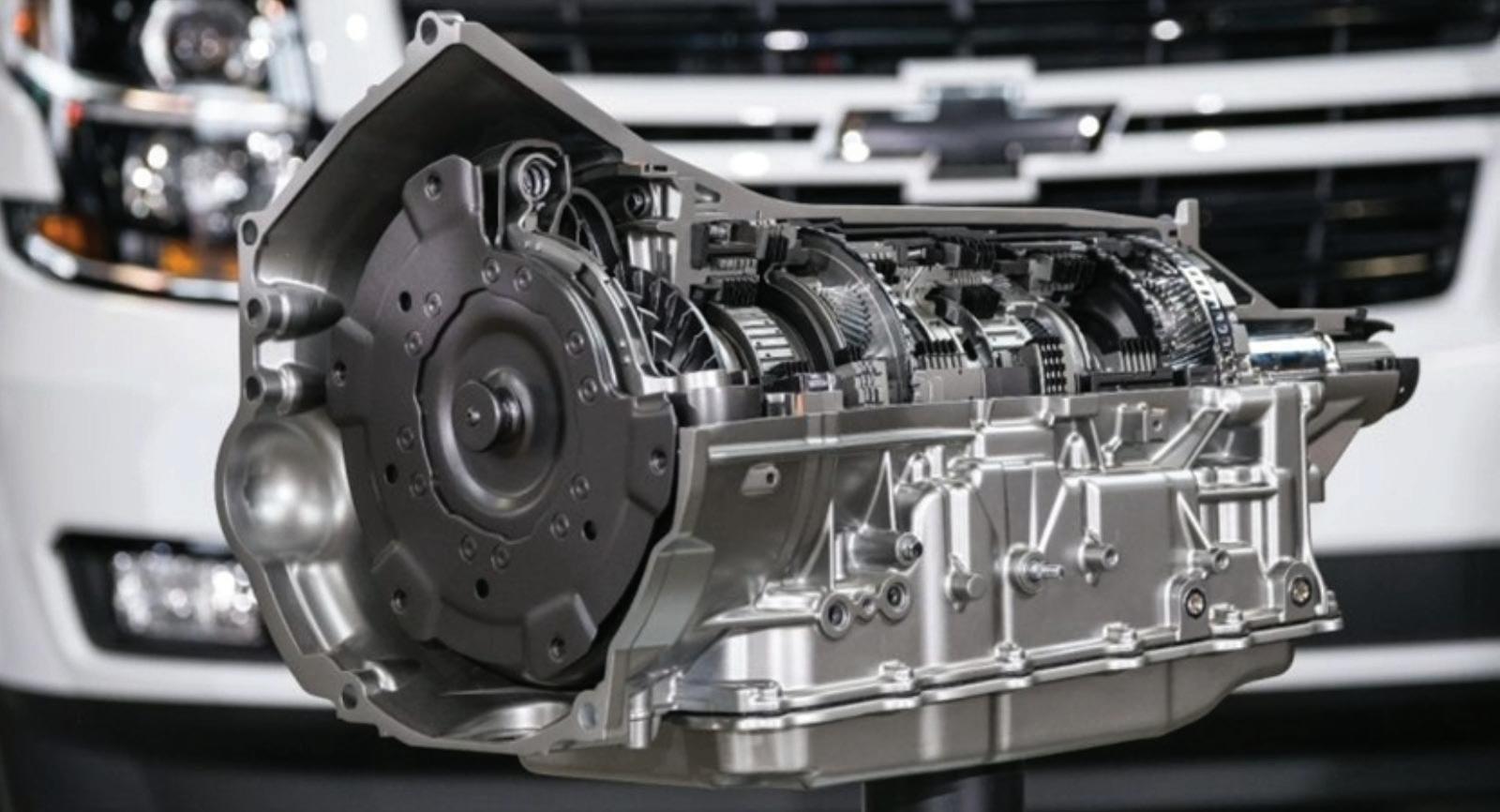
GM and Ford 10-Speed Transmissions
Why precision, fluid control, and diagnostic discipline matter more than ever
BY JEFF TAYLOR
OVER THE PAST DECADE, automatic transmissions have changed more than at any other time in the modern service era. What were once largely hydraulic devices with a handful of electronic inputs are now tightly integrated electro-hydraulic systems where software logic, adaptive learning, valve body design, electrical integrity, and fluid behavior all work together. When everything stays within its intended operating window, modern 10-speed transmissions deliver strong acceleration, smooth drivability, and impressive fuel efficiency.
When something drifts outside that window, the resulting complaints are often subtle, inconsistent, and some of the most difficult technicians encounter.
The frustration surrounding modern 10-speed units isn’t because they’re inherently weak or poorly engineered. The frustration comes from their precision. These transmissions work with little margin for deviation. Slight changes in fluid characteristics, hydraulic sealing, electrical stability, or engine torque delivery can create symptoms that feel significant while
leaving little obvious diagnostic evidence behind. What worked as a diagnostic approach on older four-, five-, or even sixspeed units often falls short here.
Precision Over Tolerance
Despite the heavy involvement of software, torque flow is still the foundation of automatic transmission operation. Planetary gearsets still route engine torque through multiple clutch elements that must apply and release in carefully timed sequences. What’s changed is how tightly
PHOTO BY JEFF TAYLOR
those sequences are controlled. Modern 10-speed transmissions routinely manage overlapping clutch events, often under light throttle and low engine load, where fuel-economy targets are most aggressive. The control module assumes that hydraulic pressure rise, clutch friction behavior, and response times will behave exactly as calibrated. When those assumptions are no longer valid, shift quality suffers immediately, often without setting diagnostic trouble codes.
Achieving 10 forward ratios in a compact package requires compound planetary gearsets and shared clutch elements. The benefit is closer-ratio spacing, quicker acceleration, and improved efficiency. The trade-off is reduced tolerance for variation. In older fourand five-speed units, small pressure delays or friction changes might go unnoticed. In a 10-speed, those same variations can produce flares, bind-ups, delayed engagements, or harsh shifts that quickly draw attention. As a result, the diagnosis must focus on clutch control accuracy rather than simply confirming that a gear exists.
The Valve Body: The Hydraulic Foundation
Although software commands modern transmissions, the valve body remains the hydraulic foundation of the system. Solenoids depend on clean passages and a predictable pressure response to regulate clutch apply timing accurately. Wear, contamination, or internal leakage can alter pressure delivery just enough to create noticeable drivability complaints. One of the most challenging aspects of diagnosing these issues is that they often don’t trigger immediate fault codes. Instead, adaptive strategies compensate by increasing pressure or altering timing. That compensation may mask the underlying problem temporarily, but it also increases stress on components and eventually reaches its limit.
Transmission Fluid: An Active Control Element
One area that can’t be overstated on mod-
ern 10-speed automatic transmissions is the role of transmission fluid—not just as a lubricant, but as an active control element. These units depend on extremely specific friction characteristics to achieve the clutch timing and overlap strategies programmed into the control module. When the fluid doesn’t behave as expected, the transmission compensates, and those compensations have limits.
Unlike older designs that tolerated a wide range of fluid behavior, modern 10-speeds operate within extremely narrow friction windows. The clutch packs are calibrated around a specific coefficient of friction and a predictable rate of change as pressure is applied. Even small deviations can alter apply timing enough to create harsh shifts, delayed engagements, or light-throttle shudder. This is why “close enough” fluid often works briefly and then fails. The transmission adapts around the new friction behavior, but as the fluid shears, heats, or degrades, those adaptations quickly reach their ceiling.
Using the correct OEM-specified fluid isn’t about branding or warranty language. It’s about ensuring that the friction curve the software expects actually exists in the transmission. Universal or multi-vehicle fluids may meet viscosity requirements, but they often struggle to maintain longterm friction stability in high-load, highshift-frequency applications like 10-speeds. Once friction stability is lost, the transmission begins chasing shift quality with
pressure, which accelerates wear and increases heat. By the time the complaint becomes consistent, the root cause is often misidentified as a hardware failure. Fluid condition is just as important as fluid type. Extended service intervals, heavy towing, or repeated high-temperature operation can degrade even the correct fluid. As fluid shears and friction modifiers break down, the clutch applies profile changes. The transmission may still function, but shift quality degrades slowly and intermittently. This explains why some vehicles feel acceptable cold and act up hot or behave differently day to day. In these cases, a complete fluid exchange using the correct specification is often the only way to restore a stable baseline before further diagnosis can be trusted.
Ford and GM Differences
The jointly developed Ford–GM 10-speed transmission architecture highlights just how sensitive these systems are. While Ford and General Motors share the same basic hardware design, the transmissions aren’t interchangeable in behavior or service approach. Ford’s versions, including the 10R80 and 10R140 families, emphasize early upshifts and aggressive torque management. GM’s calibrations for the 10L80 and 10L90 place greater emphasis on torque converter clutch modulation and partial lockup strategies. The hardware may look similar, but the control philosophy isn’t. As a result, fluid behavior becomes critical, and shortcuts
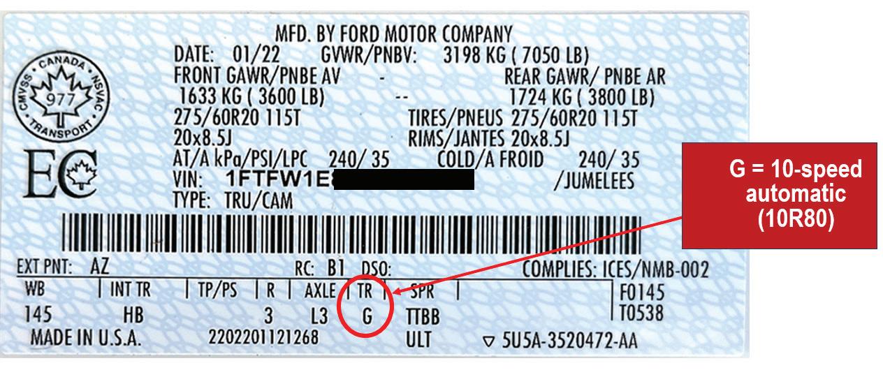
FORD DOOR jamb labels identify axle ratio and differential type, along with transmission codes used to confirm the correct transmission, fluids, parts, and service procedures before diagnostics or repairs.
PHOTO BY JEFF TAYLOR
quickly show up as drivability issues. These transmissions operate within extremely narrow control margins. Multiple clutches often transition simultaneously, and the control module assumes a predictable relationship between commanded pressure and torque capacity. When fluid characteristics change due to incorrect fluid, extended service intervals, heat, or shear breakdown, the control module compensates. That compensation works for a time, but once adaptive limits are reached, symptoms become more frequent and more severe.
Common Failure Patterns
What field experience is starting to show is that many of the internal failures on Ford and GM 10-speed transmissions aren’t random. The same components tend to fail in the same ways, which lines up with how tightly these units are calibrated and how little tolerance they have for wear or dimensional change. Once a component begins operating outside that window, the transmission doesn’t fail immediately. Instead, it compensates, and that compensation often becomes the problem.
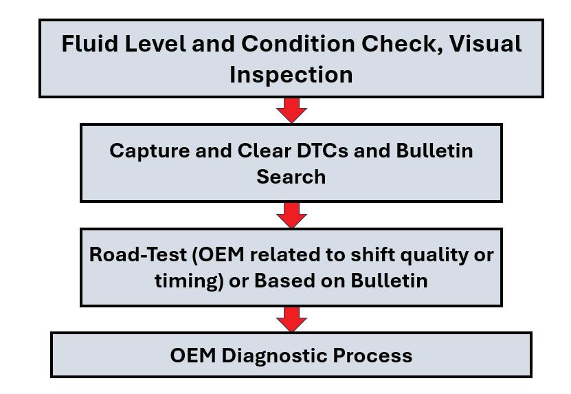
CONTRIBUTED GRAPHIC
before proceeding into OEM-specific diagnostic procedures.
Clutch drum and outer shell wear is just one example of this issue. Clutch packs are known to wear grooves into the drum or shell they run against, which interferes with proper apply and release. Once this happens, the clutch may drag, release late, or apply unevenly. The control module reacts by adjusting pressure and timing, but those changes increase heat and load on the remaining components. Over time, the damage accelerates, and what began as a shift quality complaint turns into a hard mechanical failure.
The same pattern shows up with clutch pack movement under load. In high-torque or aggressive shift conditions, clutch packs that no longer fit tightly can begin to move or “hammer” against the drum. Once that movement starts, engagement consistency is lost. The transmission may still shift, but timing becomes unpredictable. No calibration update can adjust for a clutch pack that’s no longer mechanically stable in its bore. These mechanical issues often show up indirectly in scan data rather than as obvious hard faults. Common diagnostic trouble codes associated with early or developing problems include ratio and performance codes such as P0731–P0736, pressure control or solenoid performance codes like P0746, P0747, P0776, and torque converter clutch-related codes such as P0741 or P0742. In some cases, technicians
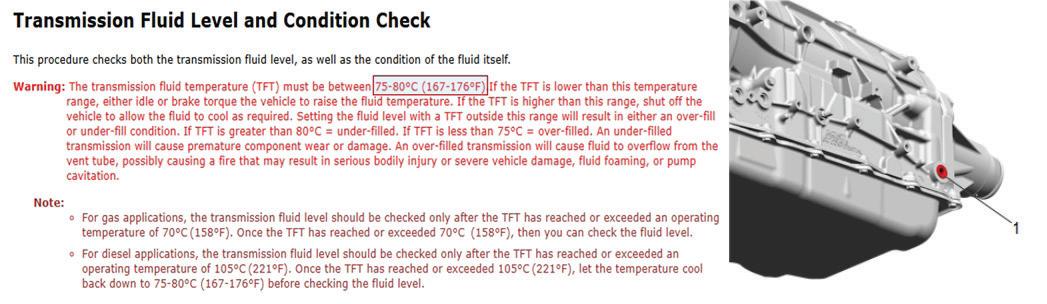
FOR A 2022 Chevrolet Sierra equipped with a 10L80 transmission, OEM procedures require the fluid level to be checked only within a specified Transmission Fluid Temperature range. Verifying TFT before setting fluid level is critical to avoid under- or over-fill conditions that can lead to shift quality issues or internal component damage.
CONTRIBUTED GRAPHIC
THIS CHART shows the initial diagnostic sequence for transmission concerns, starting with fluid level and condition checks, followed by DTC capture, bulletin review, and a controlled road test. These steps ensure accurate information is gathered
NEW TO NORTH AMERICA A LEGACY EVERYWHERE ELSE
NINE DECADES OF EUROPEAN ENGINEERING HERITAGE. OE-SPEC TOLERANCES. PREMIUM MATERIALS .
WATER PUMPS BUILT FOR TECHS WHO WON’T SETTLE FOR “GOOD ENOUGH.”
North America, meet Dolz water pumps, a proven name trusted around the world and now available here. Built with OE-spec tolerances and premium materials that reflect generations of craftsmanship, Dolz brings 90 years of precision engineering to technicians who expect more. Join the professionals who refuse to compromise on quality.
Get to know a Legacy. Get to know Dolz.



may also see excessive shift time data without an active code, which is often an early indicator that a specific clutch circuit is struggling to apply on time.
What’s important to understand is that these codes don’t necessarily point
to a single failed part. More often, they indicate that the transmission is no longer able to achieve the commanded result within the expected time or pressure range. That can be caused by internal leakage, worn sealing surfaces, degraded
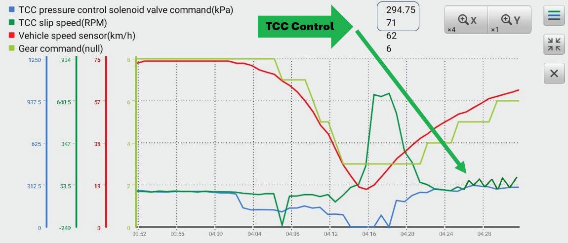
SCAN DATA shows an elevated Torque Converter Clutch slip speed of approximately 25–30 RPM during steadyspeed driving at 25–50 MPH, even though TCC applied pressure is commanded and gear state remains unchanged. This pattern indicates the TCC is not fully holding under load, a common sign of degraded transmission fluid affecting clutch lockup performance.
CONTRIBUTED GRAPHIC
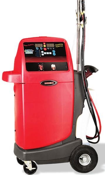
A TRANSMISSION fluid exchange machine is used to replace degraded fluid with the correct specification fluid during a controlled service procedure. This process ensures consistent fluid replacement throughout the transmission and oil cooler, helping restore proper torque converter clutch operation and shift quality.

CONTRIBUTED PHOTO


























fluid, or mechanical wear that the software is trying to manage around.
Hardware Evolution: Ford Redesigns
Bushing movement in the CDF drum is
something that shows up repeatedly on Ford 10-speed units. The CDF drum is responsible for routing apply pressure to multiple clutch circuits, so when the bushing shifts, sealing surfaces are dam-
aged. Once that happens, pressure starts leaking between circuits, apply pressure drops off, and shift timing becomes inconsistent. Ford revised the drum in late 2022 to address this.
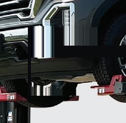
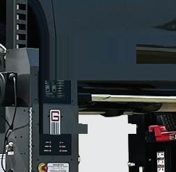
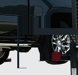
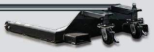
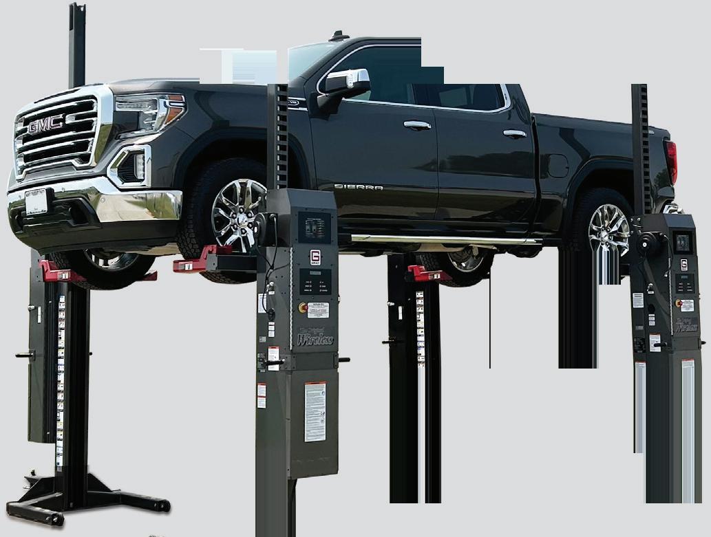
Gray Manufacturing’s newest mobile column lift, WPLS-50, has a 5,000 lb per column capacity for the light duty truck industry. It features a T-Handle design for easy maneuverability in tighter workspaces, lockable swivel casters and adjustable lift forks. The self-contained modular design includes a blinking light system for self-directing operational setup and a color-coded display background to indicate lift status.
The WPLS-50 provides a fast, safe and ergonomical lift system for technicians to service and maintain light duty vehicles.













The same issue shows up in Ford’s redesign of the 10R140 valve body used in March 2023-and-later units. Externally, it looks much the same, but internally the control strategy changed. The “A” and “B” latch valves were eliminated after wear issues showed up in service. Once those valves began to overstroke or stick, pressure control became inconsistent, which directly affected clutch apply timing and shift quality. Ford addressed this by revising clutch control valve geometry and updating control logic, so latch valves were no longer needed. Additional changes to the torque converter clutch control valve appear aimed at softening apply rates by restricting flow hydraulically rather than relying solely on software. It’s a clear example of hardware, hydraulics, and calibration evolving together.
Converter Lockup and Engine Integration










Early torque converter clutch lockup adds another diagnostic challenge. Many 10-speed transmissions apply the converter clutch as early as 16 to 20 mph and operate with extremely low slip, often under 10 rpm. Once the converter is locked, the driveline becomes tightly coupled. Any irregularity in engine torque delivery is transmitted directly through the transmission. Misfires under load, incomplete combustion events, or unstable torque output can feel exactly like converter shudder or clutch problems. This is why engine-related issues are often misdiagnosed as transmission failures on these vehicles. Reviewing misfire monitors and load-related data becomes critical, especially when complaints in-
volve light-throttle shudder or vibration during low-speed cruising.
Software, Relearns, and Electrical Stability
The transmission software version is the other half of this equation. Modern 10-speed transmissions are constantly adapting to wear, fluid behavior, and driving style. Those adaptations are built around the calibration currently installed in the control module. When software is outdated, the transmission may be using pressure targets, shift schedules, or converter clutch strategies that no longer reflect real-world experience or known problem areas. This is why many technical service bulletins address shift quality through calibration updates rather than parts replacement.
Updates usually change clutch fill timing, pressure ramps, and how the converter clutch is applied. In some cases, they also change how quickly the unit adapts and how much correction it allows. Updating software alone may improve shift feel at first, but if fluid condition or hydraulic integrity isn’t right, that improvement usually doesn’t last.
Relearns are just as important after fluid service, valve body work, or calibration updates. These units don’t relearn themselves in a short drive. The control module has to see the same conditions repeatedly to reset clutch fill volumes and timing. When relearns are rushed or interrupted, the transmission often comes back with the same complaint. Most of the time, it wasn’t fixed and then failed again—it was never fully relearned in the first place.
Electrical integrity is another commonly overlooked factor. Tenspeed transmissions rely on stable reference voltages to control solenoids precisely. A marginal battery may still crank the engine and avoid
setting obvious electrical codes, yet create low-voltage events during cranking or stop-start operation that disrupt solenoid control and adaptive memory. This explains vehicles that shift acceptably after












a relearn one day and poorly the next. Without a stable electrical foundation, learned shift strategies can’t be kept reliably, regardless of how many times a relearn procedure is performed.







































































Diagnostic Discipline and Scan Data
Diagnostic discipline matters more than ever with these transmissions. Generic complaints such as “slipping” or “shifting weird” provide little usable information.
Load, throttle angle, temperature, and road speed all influence how a 10-speed behaves. Many complaints only occur under light acceleration, during low-speed cruising, or once the transmission is fully warm.
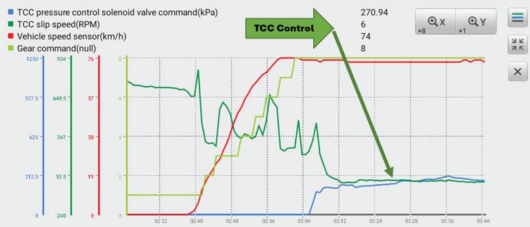
AFTER THE transmission fluid exchange, scan data shows stabilized Torque Converter Clutch slip with consistent apply pressure, smooth vehicle speed, and uninterrupted gear command. Reduced slip confirms the shudder condition has been corrected and normal TCC operation restored.
CONTRIBUTED GRAPHIC
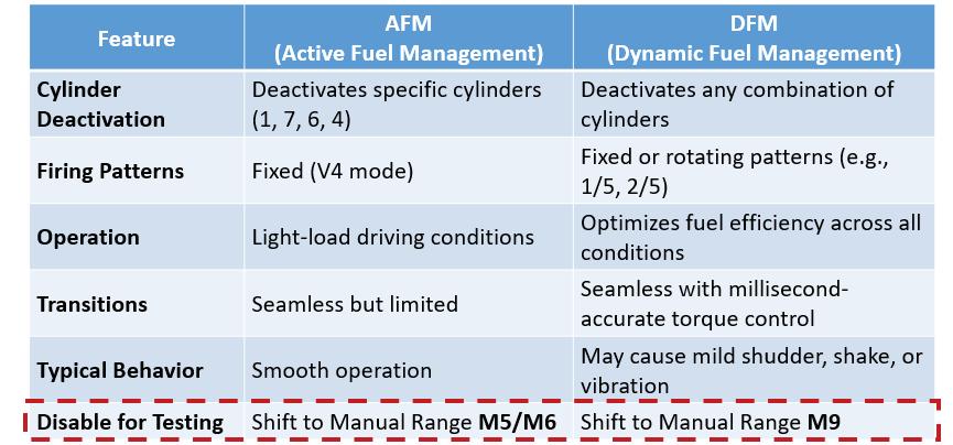
THIS TABLE compares GM Active Fuel Management and Dynamic Fuel Management, with emphasis on the transmission manual range selections used to disable each system during diagnostics—M5/M6 for AFM and M9 for DFM—to help isolate drivability concerns.
CONTRIBUTED GRAPHIC
Others appear only after extended highway driving. Without duplicating those conditions, it’s easy to miss the problem entirely or misinterpret scan data that looks normal in a controlled environment. Modern scan tools provide valuable data, but that data must be interpreted correctly. Shift duration is one of the most useful metrics available. On a unit that’s working properly, shift timing stays consistent from gear to gear. When one clutch starts taking noticeably longer to apply than the rest, it usually points back to that circuit rather than a general mechanical problem. Looking at engine load at the same time helps put that into context. High calculated load at light throttle can push shifts later or cause stacked shifts, which often feels like a transmission issue even when the source is elsewhere.
Heat Management and Fluid Condition

Transmission heat management can’t be ignored. Ten-speed transmissions are compact, heavily loaded, and shift frequently, all of which generate heat. Elevated temperatures accelerate fluid shear and reduce friction stability, narrowing the margin for accurate clutch control. This is where time-in-failure becomes critical. A vehicle that’s been driven for months with a known shift complaint has likely been operating with compromised fluid and elevated temperatures. In those cases, software updates or valve body repairs may no longer be sufficient to restore normal operation.
Transmission pan inspection is still one of the most useful reality checks on these units. Fluid condition and debris tell a story about how long the problem has been developing and whether a limited repair still makes sense. Light clutch material may point to early wear that can be corrected. Heavy debris or a burnt smell usually means the damage has progressed beyond that point. Knowing when a transmission is no longer a practical candidate for a targeted fix avoids setting expectations that can’t be met.


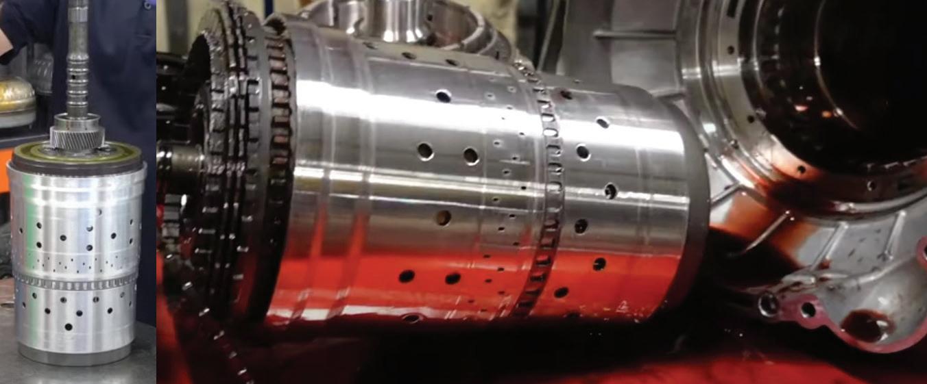
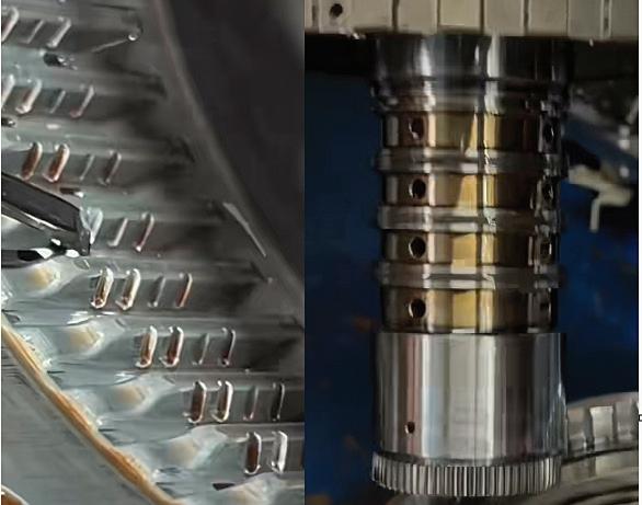
THIS IMAGE compares the GM clutch carrier (left) and the Ford 10-speed CDF drum (right), both of which are known wear points. Bushing movement and bore wear can damage sealing surfaces, leading to internal pressure leakage, reduced clutch apply pressure, and inconsistent shift timing.
PHOTO BY JEFF TAYLOR














Another source of confusion is how differently these transmissions age in the real world. Some run well past 100,000 miles with few complaints, while others develop problems much earlier. That spread often comes down to driving habits and how the unit adapted early in its life. It also explains why shortcuts sometimes seem to work, at least for a while.
Technical Service Bulletins and Software Updates
Technical service bulletins and software updates continue to address specific symptoms, but they rarely tell the entire story. In many cases, updates improve shift feel by altering pressure targets or timing windows, masking underlying hydraulic or friction-related issues. When symptoms return, technicians are often left chasing
the same complaint again. Understanding when software is addressing a root cause versus when it’s compensating for one is critical to long-term repair success.
Conclusion: Precision Demands Discipline
Modern Ford and GM 10-speed automatic transmissions aren’t weak. They’re precise. Fluid behavior, hydraulic integrity, electrical stability, engine torque delivery, and software strategy are inseparable. Ignoring any one of those elements leads to misdiagnosis and repeated repairs. For technicians willing to approach these units as integrated systems rather than collections of parts, transmission diagnosis becomes more predictable and far less frustrating. Precision demands discipline, and these transmissions reward it.

JEFF TAYLOR is a seasoned professional at CARS Inc. in Oshawa with 40 years in the automotive industry. As a skilled technical writer and training developer, he holds licenses in both automotive and heavy-duty vehicle repair. Jeff excels in TAC support, technical training, troubleshooting, and shaping the future of

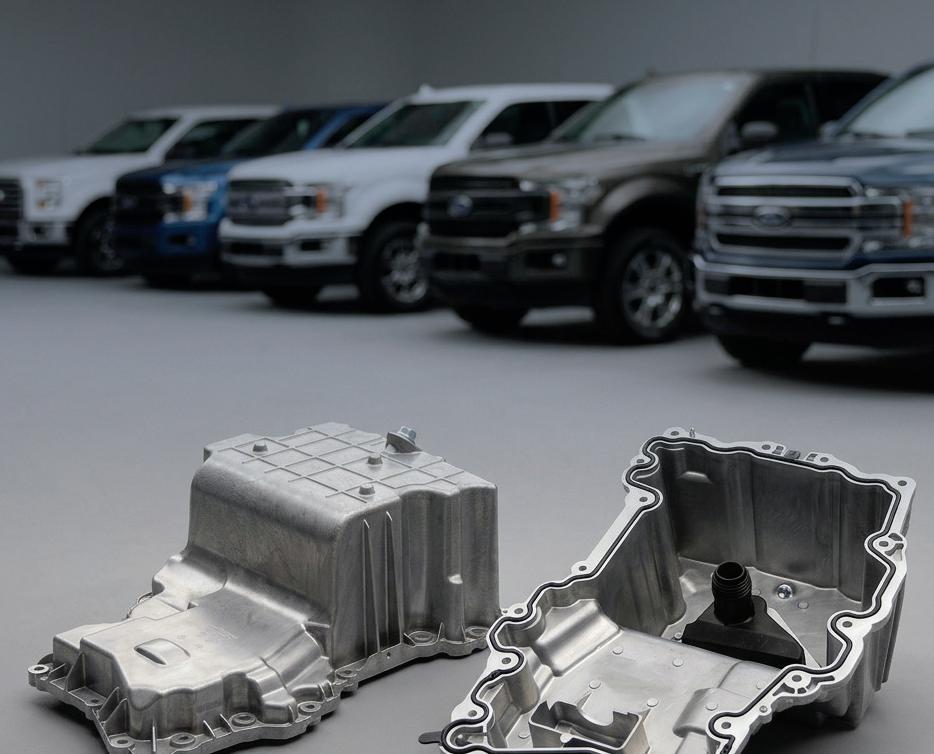














WEAR IN the Ford 10-speed CDF drum allows clutch packs to stick, release late, or apply unevenly as the friction plates groove the drum surface (left). The right image shows the sealing lands responsible for containing apply pressure. When bushing movement or clutch pack instability damages these areas, fluid leaks between circuits, apply pressure drops occur, and shift timing becomes unpredictable. Once sealing integrity is lost, no calibration
























EXTENSIONS
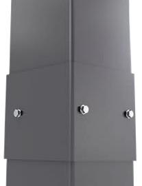
COLUMN EXTENSION ADDS 24" OF HEIGHT























































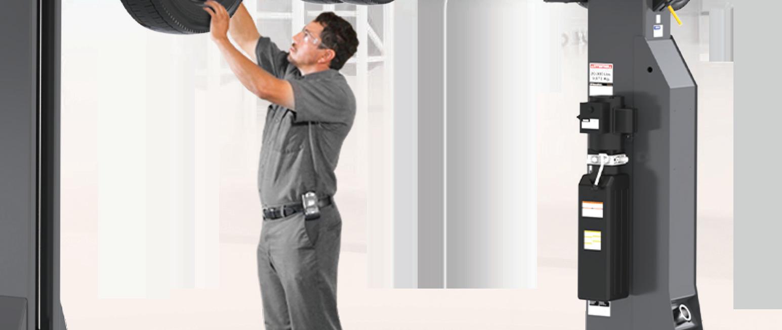



















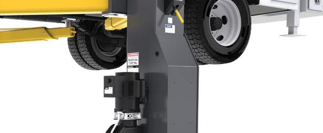





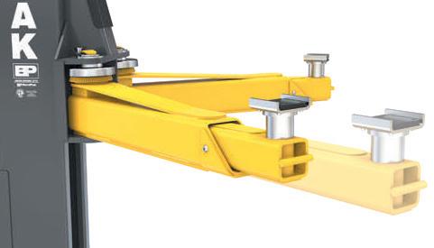











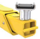








A versatile choice for mixed fleets, BendPak’s new 16AP and 20AP Series heavy-duty two-post lifts easily take on Class 1 through 5 vehicles, from passenger cars to commercial trucks and vans. They reach further, lift higher and deliver greater stability than other lifts, all while protecting technicians with unmatched safety systems and ergonomics. With fewer moving parts, they’re easier to maintain, less prone to wear, and more cost-effective to operate. Maximize your uptime and efficiency with BendPak’s heavy-duty lifts — delivering superior performance and unmatched value. To learn more or to shop now, visit bendpak.com or call us at 1-800-253-2363







Navigating Customer Communication in the DIY Automotive Era
A new era of informed—and sometimes misinformed—customers demands shops adopt transparent, collaborative communication strategies
BY NOAH NELSON




THE DYNAMIC BETWEEN VEHICLE OWNER AND TECHNICIAN has fundamentally changed, moving past the simple transactional relationship built on blind trust. Today, the service bay is frequently the stage for interactions with a highly informed, yet often misinformed, customer base. These modern vehicle owners, fueled by a desire for cost savings, are often DIY enthusiasts. They only bring their cars in for major, complex, or persistent issues, and they frequently arrive with a pre-existing diagnosis formed long before the car reaches the lift. This shift demands a new approach to customer communication centered on transparency and education.
The Rise of the Informed Customer and the Internet Diagnosis
The transformation of the automotive service industry into a visible, public domain began modestly with printed resources like Haynes and Chilton service manuals. However, the true revolution exploded with the advent of the internet. Platforms like YouTube, TikTok, and vast online forums have effectively lifted the veil on vehicle repair, creating a new and challenging reality for the shop floor.
Customer Empowerment and the Right to Repair
Vehicle owners have successfully pushed for and advocated for measures like Right to Repair, demanding affordable access to professional-grade service information. This has also driven a push for increased shop transparency, evidenced by the popularity of digital inspections.
Accessibility of Tools and Information
It’s easier and cheaper than ever for a motivated owner to acquire the resources, basic diagnostic tools, and procedural information necessary to attempt their own repairs.
The Competence Gap: The Illusion of Comprehensive Understanding
While access to information has democ-
ratized, the critical components of experience, nuanced skill, and deep systematic knowledge required for complex diagnostics and repairs remain firmly with the professional. The internet often only provides the procedural steps, creating an illusion of comprehensive understanding that is deeply flawed.
Modern vehicles are intricate ecosystems of networked modules, complex wiring harnesses, and sophisticated electronic control units. The idea that a 10-minute video can provide a comprehensive understanding of a failure, while ignoring critical variables like prior modifications, vehicle history, or environmental wear, is untenable. This lack of necessary context frequently leads to significant friction when a customer, equipped with an Internet diagnosis, seeks to debate a professional assessment that contradicts their online research.
Understanding the Friction: The Dunning-Kruger Peak
The core of the conflict in the service bay is a psychological phenomenon best explained by the Dunning-Kruger Effect. In this context, a customer mistakes a brief online tutorial or a successful, isolated repair attempt for deep engineering and diagnostic knowledge, a condition known as the illusion of explanatory depth.
The Conflict
The customer arrives having invested time and effort into finding a perceived solution on the internet. When the professional diagnosis, derived from actual vehicle data and experience, contradicts this perceived solution, the customer feels their newfound expertise is being dismissed. This instantly escalates the conversation from a simple technical disagreement over parts and labor to a personal clash of competence and authority.
The Flaw of the Internet Diagnosis
Online content is heavily focused on procedural steps (e.g., how to swap a sensor
or where to locate a fuse) but lacks the essential diagnostic logic (how to verify signal integrity, pinpoint the root cause, or interpret live sensor data). The customer is prepared to execute a step, but not to perform the comprehensive analysis that justifies that step.
The
Shop’s
New Role: Refiners of Information
The professional’s job has fundamentally evolved. It’s no longer just about fixing the car—it now involves guiding the customer from their online peak of confidence back to the valley of reality, the point where true learning and acceptance occur. The strategy must shift from defensively dismissing the customer’s research to actively refining and confirming it. The goal is to show the customer that their video was a useful starting point, but the specific, undeniable data from their unique vehicle tells a more complex, accurate story that only a professional can interpret.
Strategies for a Collaborative and Transparent Service Model
Transparency as the Shop’s New Currency
Since customers are already pre-conditioned to look for visual proof and validation on their mobile devices, the most effective way to handle skepticism and doubt is to show, not just tell. Transparency is no longer a marketing buzzword; it’s a fundamental, non-negotiable requirement for the professional shop. Digital Vehicle Inspections
DVIs are the single most powerful de-escalation tool available. A customer can’t easily argue against a high-definition photo of their own leaking water pump, a short video clip demonstrating the excessive play in a failing wheel bearing, or a screenshot of a live data graph showing an out-of-spec reading. This technology meets the customer in the digital space they already trust and provides objective, irrefutable evidence.
Detailed, Narrative Documentation
Service write-ups must move beyond simplistic, three-word descriptions like “Fixed broken wire.” Documentation should be narrative, detailed, and written like a technical story: “Traced the 5V reference signal to Pin 14 of the ECU, found intermittent signal dropout caused by a harness rub-through near the motor mount on the driver’s side. Repaired and heat-sealed the harness section.” This detailed narrative serves a dual purpose: it fully validates the time spent on the diagnostic charge and proves the repair was surgical, data-driven, and not based on guesswork. It transforms what could have been a defensive interaction into a valuable educational moment, positioning the shop as the ultimate, indisputable authority on that specific car’s history and issue.
Reclaiming the Value of the Diagnostic Charge
Customers often view the diagnostic fee as an unnecessary gatekeeper tax or a charge for simply “reading a code.” The shop must proactively change this narrative by emphasizing that the customer is paying for expert interpretation, special-
ized tools, and certainty, not just a simple code readout.
Testing, Not Guessing
The technician must explain that the trouble code (“P0171 Lean Condition”) is merely the starting line for the diagnosis, not the finish. The diagnostic fee covers the shop’s investment in specialized oscilloscopes, required factory-level software subscriptions, proprietary wiring diagrams, and, most importantly, the seasoned experience needed to differentiate a simple component failure from a complex wiring fault or a software glitch.
The Medical Analogy
Frame the diagnostic fee as the lab work or specialist consultation for the vehicle. It is the necessary insurance policy that prevents the catastrophic financial risk of the parts cannon, the expensive, time-consuming cycle of blindly replacing components based on internet guesswork.
The Value Proposition
By explaining the price in terms of professional certainty, risk mitigation, and the avoidance of costly re-repairs, the

shop reinforces that professional skill is a premium service that ultimately saves the customer money and frustration in the long run.
Collaboration: Swallowing the Professional Ego
It’s a natural human reaction for seasoned technicians to feel insulted when an inexperienced customer attempts to tell them how to do their job. However, success in the modern era requires letting go of this defensiveness and consciously turning a perceived challenge into a collaboration.
The “Yes, and” Approach
The technician must validate the customer’s effort and research: “That’s a great catch on that Technical Service Bulletin; I saw the same post regarding the common failure mode. Now, let’s look at your vehicle’s specific scan data and live tem-
peratures to verify if that TSB’s symptoms apply to your unique situation.” This approach instantly lowers defensive walls, acknowledges the customer’s effort, and fosters a feeling of partnership rather than confrontation.
Honesty and Humility
When a customer genuinely provides a solid, niche piece of information (a known, obscure issue for a specific model year), the shop should admit it and integrate it. This makes the shop look honest, self-assured, and professional, not less competent. It powerfully demonstrates that the correct, effective repair is the highest priority, superseding professional pride.
Act as a Curator of Information
Proactively share a trusted creators list (known, credible industry sources like ScannerDanner or South Main Auto)
with DIY-minded customers. This signals to the customer that the shop isn’t afraid of informed clients and confidently positions the shop as the ultimate, reliable source of truth, helping the customer distinguish between a genuine professional standard and an amateur hack.

NOAH NELSON serves as technical editor for Motor Age. He started his 20-plus-year career as a lube technician and evolved through the ranks into district management. Now an ASE Master Technician, Noah leverages his diverse background to provide the industry with practical, real-world technical tips, guidance, and insights.







Cleaning Up the Air
BY CRAIG VAN BATENBURG
Why I invited the Environmental Protection Agency into my shop—and why it should matter to you

WHEN I WAS ASKED BY THE EPA to show up with a camera crew to film my shop regarding hazardous waste, I said, “Yes.” Why? Have you been following the national effort to clean up tailpipe emissions?
Do you work in a state that still requires some form of vehicle emissions testing? Some states focus on specific urban counties rather than statewide programs. Here’s
a list of states that are serious about clean air: California, Arizona, Colorado, Connecticut, Delaware, Georgia, Illinois, Indiana, Maryland, Massachusetts, Missouri, Nevada, New Hampshire, New Jersey, New York, North Carolina, Ohio, Pennsylvania, Texas, Utah, and Wisconsin. Other states have partial areas. Here’s a brief history of how we got here.
The First Federal Environmental Laws
The first federal legislation to address air pollution in the United States was the Air Pollution Control Act of 1955, which provided research funds. The first Clean Air Act was signed into law on December 17, 1963, authorizing federal programs for pollution control. The U.S. Environmental Protection Agency was
SMOG OVER Ogden, Utah. CONTRIBUTED PHOTO
established on December 2, 1970, by President Richard Nixon to consolidate federal research, monitoring, and enforcement activities into one agency. It was created in response to growing public concern over pollution, following the first Earth Day in April 1970. The Clean Air Act Amendments of 1990, signed by President George H.W. Bush, were comprehensive changes to the 1970 Act. Technicians had to go back to school to get up-to-speed on newer cars, soon to be equipped with a 16pin connector. These revisions to the U.S. Clean Air Act were designed to address four major environmental threats: acid rain, urban air pollution (smog), toxic air emissions, and stratospheric ozone depletion (known today as global warming). America was going after sulfur dioxide, tighter auto emission standards, and enhanced enforcement. Lobbyists were heading to every state capital and Washington, D.C., to make sure our collective voices were heard. The Automotive Service Association led the way.
California vs. the EPA
The 1990 requirements weren’t robust enough to clean up the air as fast as citizens wanted it done. Los Angeles had a huge smog problem. A lawsuit was sent to the EPA asking them to let California do more. The California Air Resources Board was enforcing standards that required a phase-in of low-emissions vehicles, ultra-low-emissions vehicles, and zero-emission vehicles to address the smog. While California was working on local solutions, national efforts were heating up as the American Lung Association was suing the EPA to force stricter nationwide sulfur dioxide standards. It was a time of great debate and typical political gamesmanship.
At the same time, oil companies and auto manufacturers were beginning to invest heavily in producing cleaner fuels and electric vehicles to meet these new, strict requirements, while also taking California to court. California was a leader,
with a few other states following its lead, especially Massachusetts.
Massachusetts and the Supreme Court “Massachusetts v. EPA” is the summary of that court case.
The 1990 Clean Air Act allowed the Environmental Protection Agency to regulate greenhouse gases because they qualify as air pollutants. For those of you who love chemistry and science, climate change or global warming (pick the word group you like)—has been proven beyond any doubt that we have a problem. Burning fossil fuels adds carbon dioxide to the atmosphere.
Twelve states, as well as various cities and organizations, sought to require the Environmental Protection Agency to regulate greenhouse gases, like carbon dioxide, under its authority to regulate pollutants. The lawsuit was based on Section 202(a)(1) of the Clean Air Act, a provision that requires the EPA administrator to set emission standards for air pollutants from motor vehicles.
Responding to that mandate, the EPA had decided that it lacked authority to regulate greenhouse gases for climate change purposes. The case combined the substantive issue of whether the agency had decided correctly on these issues with the procedural question of whether the states, cities, and organizations even had standing to bring such a claim. The issue was based on the loss of coastline to rising sea levels caused by global warming. The Supreme Court said the following.
Majority Opinion
After finding that the states had standing for these types of environmental claims, Justice Stevens wrote, “The Clean Air Act does provide sufficient statutory authority for the agency to regulate greenhouse gases.” Stevens pointed out that the law provides a sweeping definition of what constitutes a pollutant, and greenhouse gases clearly fit inside that definition. He sent the case back to the agency for a reconsideration of its decision. While

AN EPA award as seen in Van Batenburg’s Garage. PHOTO BY CRAIG VAN BATENBURG
the EPA’s current reasoning for not regulating greenhouse gases was insufficient, it would have the chance to find another reasonable basis for that policy. It stated that greenhouse gases had played a key role in global warming. Challenges by states that opposed the ruling didn’t sur-


vive review by the D.C. Circuit. On April 2, 2007, the case was closed.
The Massachusetts Right to Repair Act
The Massachusetts Right to Repair Acts (2012 and 2020) mandate that automobile manufacturers provide owners


Steering and suspension parts for fleet vehicles and work trucks.
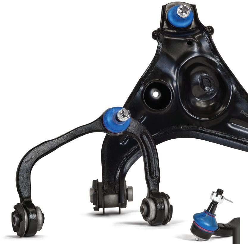


Greasable ball joints with relief valves
Cataphoretic anti-rust coating
for endurance. Designed for professionals. Built to perform.



and independent repair shops with access to diagnostic and telematics data for modern vehicles. This law allows consumers to choose repair facilities, ensuring competition and preventing dealer monopolies. This law easily passed because if you failed the state’s emissions test, you needed to fix your car. You have 60 days.
Key Aspects of the Massachusetts Right to Repair Law
The 2012 law required manufacturers to provide independent shops with the same diagnostic, service, and repair information provided to authorized dealerships for a reasonable fee.




Super-strong bushing bonding











The next law in 2020 includes access to “telematics” data starting with 2022 models. Despite intense challenges from automakers, the 2020 law was upheld by a federal judge in early 2025. The law aims to lower repair costs and increase consumer choices for maintenance, fostering competition in the automotive aftermarket. The law specifically empowers independent shops to compete with dealerships, which is a major victory for consumer choice. (Full disclosure: I own a hybrid–electric technician training center in Massachusetts and, in January 2026, reopened the shop after 22 years specializing in EVs.)
My Involvement



Most shop owners I’ve known would like the government to stay out of their business and their shops. In 1992, I flew down to Florida to attend a Mitch Schneider management class sponsored by the Broward County Automotive Service Association. Prior to that, I hadn’t engaged much with other shop owners. The reason was I owned and worked as a mechanic at a small independent Honda shop and never felt connected to general repair shops. I’d opened my shop as a one-man business in 1977. The Civic was just out of warranty and the Accord was a year old. Fifteen years later, in sunny Florida,











































































I sat with 50 shop owners and their techs and realized what I was missing: being a part of something much bigger—the auto repair industry. This one-day Saturday class was great. I had dinner that night with Mitch and my wife, Deb. Soon after that, I joined ASA. Two years later, with a few Massachusetts shops, we started our own chapter. That was before the internet, free training at lunchtime, OBDII, and electric cars.
Doing my part to improve all shops, I stepped up as president of ASA Massachusetts. There were ASA chapters all over America back then. Today it’s very different. In some ways better, but the
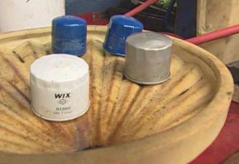

strong personal connections with peers is limited. Yes, there are big events, but the local chapters are disappearing.
Van Batenburg’s Garage and the EPA I was asked in the mid-1990s to allow a film crew and EPA employees to visit my shop during business hours to see what we were doing to protect the land, air, and water. The document is still on the EPA’s website. Here is a part of the EPA study with slight edits.
Case Study: Van Batenburg’s Garage, Worcester, Massachusetts
Excerpts from the EPA PDF document: “Craig Van Batenburg owns and operates an auto repair garage in Worcester, Massachusetts, which includes many service features to control fluids and prevent spills. These services include recycling waste oil, antifreeze, and filters through innovative systems. Although the garage is located outside of a wellhead protection area for a backup well for the City of Worcester, the garage owner educates many area automotive technicians about proper fluid and hazardous waste handling operations through a regional automotive repair education association.”
The Van Batenburg Garage drains
oil filters for two to five days into a collection system, then crushes the filters and sends them for recycling. Used motor oil from the drained filters is combined with the used oil from automobiles and pumped directly to an on-site oil burner. A technician performs antifreeze recycling after initially testing the antifreeze by directly pumping radiators through a mobile pump station. By directly pumping antifreeze through this system, no spillage occurs. This service procedure is similar to an air conditioning service system.
Fluids Management and Spill Response Evaluation
“Van Batenburg’s Garage clearly labels and color-codes all containers for raw and used fluids. By carefully coding containers and training its staff to know about fluid management and proper spill prevention techniques, the garage protects the personal safety of its employees, generates less waste, and protects itself from fire and spills. All fluid containers are labeled by color to ensure employees don’t accidentally combine different fluids. To avoid spills, the garage uses direct pumping or drip pans that drain directly to a collection

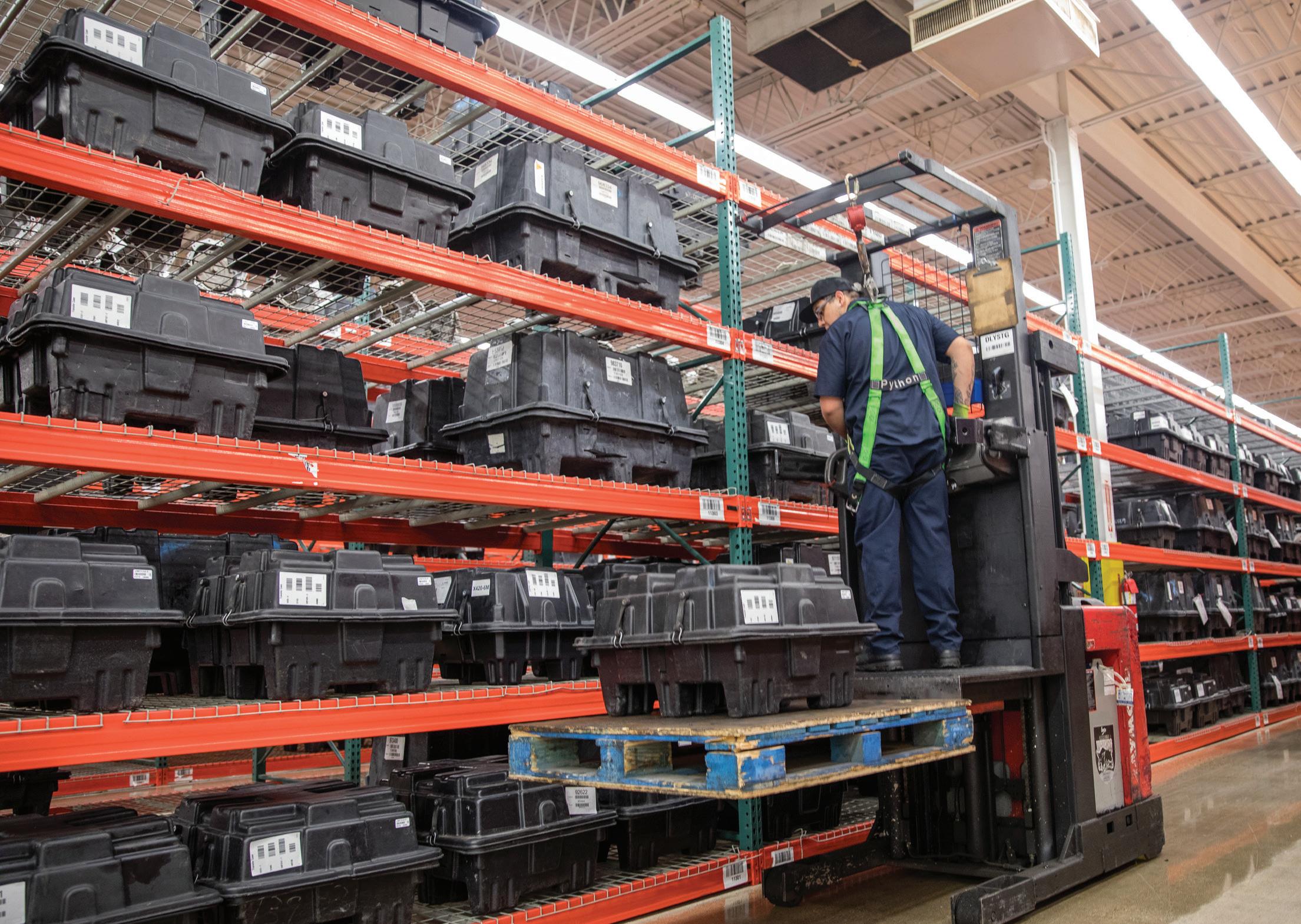
OIL FILTERS draining into a collection system. The EPA recognized Van Batenburg’s Garage as an example of “doing it right.”
PHOTO BY CRAIG VAN BATENBURG
PRESIDENT GEORGE H.W. Bush signs the 1990 Clean Air Act amendment.
CONTRIBUTED PHOTO



















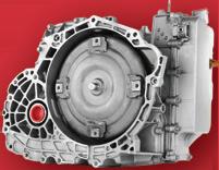





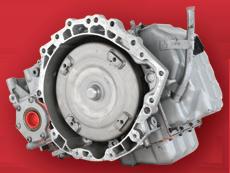





system. Spill cleanup equipment using absorbent materials is available in each service bay for easier response. Absorbent materials (pads, mats, hydrophobic mops, and floor sweeps) are used to remove medium-sized or larger spills. All fluid transfers are conducted within service bay areas, not outside. All Material Safety Data Sheets are located in an accessible location for employees.”
Conclusions: Implementing Best Management Practices
“Recycling waste fluids and used lead batteries, clearly color-coding fluid containers, training staff in fluid management and spill prevention strategies, and participating in educational outreach through a regional automotive repair education association, Van Batenburg’s Garage works on several fronts to protect groundwater quality in Massachusetts.”
Today’s Climate
The motor vehicle repair industry has been advancing rapidly in electrification. A year ago, the federal government put the brakes on EVs. Some states have added more incentives to move away from gasoline and diesel. I explain to my customers that I have no issues with the motor vehicles today; it’s the fuel in the tank that gets me out of bed each day. As you go back through history, you can see clean air has mattered for a long time. We can’t go backwards. Remembering the lessons of the last 70 years will help us predict the future. How we got here will help technicians prepare for their future. Shop owners need to be ready years before the next wave of technology heads to their service bays. I know many shop owners who do just that. EVs didn’t just appear out of nowhere. California and Massachusetts have played a big role in
recognizing the negative impact of burning fossil fuels and how we can reduce carbon dioxide. Working with the government helps everyone. You can do your part and help your techs, community, and ultimately the planet. It’s all up to you.

CRAIG VAN Batenburg is the CEO of ACDC, a hybrid and plug-in training company based in Worcester, Mass. ACDC has been offering high voltage classes since 2000, when the Honda Insight came to the USA. When EVs were introduced in 2011, ACDC added them to their classes. Reach Craig via email at Craig@ fixhybrid.com or call him at (508) 826-4546. Find ACDC at www.FIXHYBRID.com.
• Can you easily scope the J1772 connector?
• Is the problem the car or the EVSE?
• We have a break-out box designed by ACDC
• Complete with safety lockout, and a manual
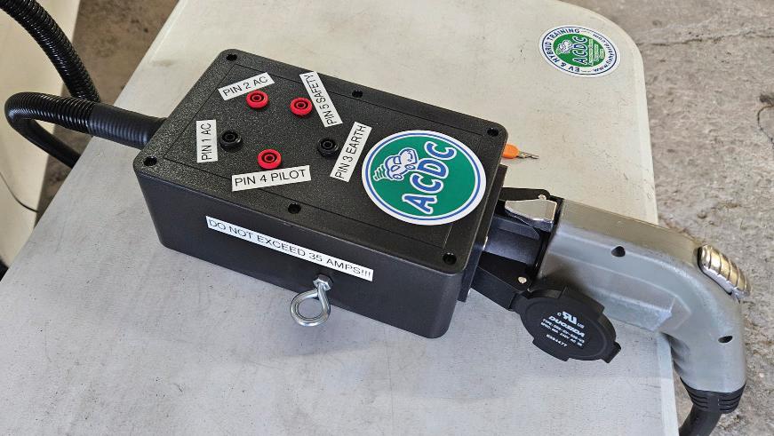
OFFICE: 508-826-4546
EMAIL: CRAIG@FIXHYBRID.COM
WEB: WWW.FIXHYBRID.COM
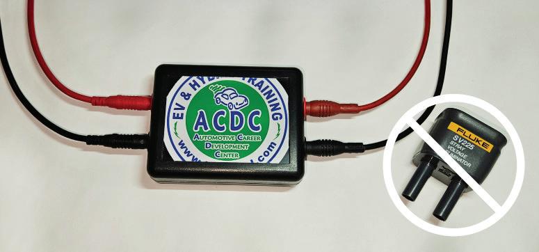
• Works on Tesla’s with an adapter $99 50 Plus S/H
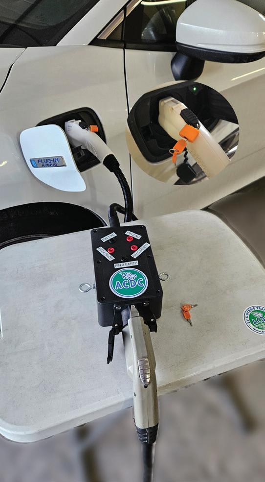
• Ghost Voltage will give you misleading DVOM readings on High Voltage systems
• How do you eliminate them?
• ACDC has engineered a solution, after Fluke stopped production of the SV225







R AISING THE STANDARDS OF
















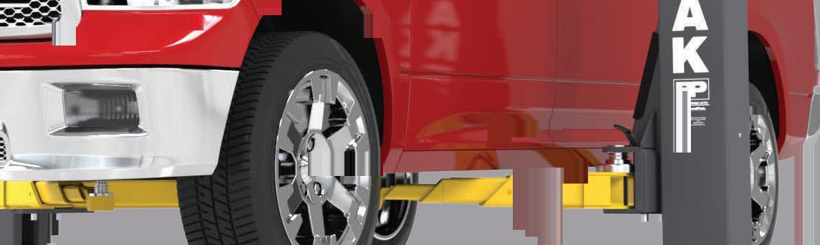























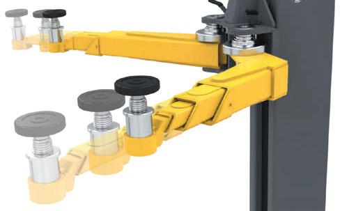






















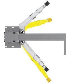

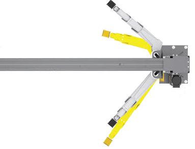




















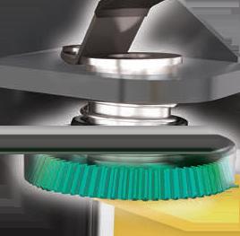































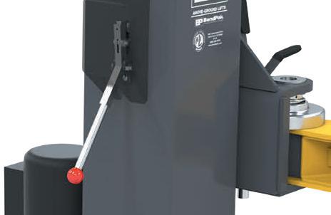
The 10AP Series combines increased lifting height with unmatched versatility, making it ideal for larger vehicles and undercarriage work. The extra height creates a more comfortable workspace for taller mechanics to perform intricate repairs on trucks or SUVs. Built for durability and safety, it features an expandable top beam and Bi-Metric ™ arms that accommodate symmetric or asymmetric lifting. Its 2-in-1 design maximizes flexibility, while efficient engineering keeps costs low and productivity high—perfect for busy shops. Check out the full line of AP-Series lifts at bendpak.com or call us at 1-800-253-2363 .



Chill It!
There’s cool advantages to next-generation refrigerants R-444A and R-456A
For shops, the change to new mobile A/C refrigerants may seem confusing, as there are risks associated with not getting it right with systems currently in use for Recovery, Recycle and Recharge. RRR machines simplify refrigerant service but are an added expense. So, purchasing a new machine to enable high-performing, low-GWP refrigerants can make owners and technicians hesitant to switch from incumbent refrigerants.
This article clarifies why Orbia Fluor & Energy Materials (OF&EM) is uniquely suited to develop next-generation refrigerants to meet the requirements of the U.S. AIM Act, which is phasing down HFC production and consumption. As a global leader in the production of refrigerants with over 70 years of experience producing refrigerants for Mobile A/C, OF&EM has some unique advantages in developing next-generation refrigerants that will address the EPA phase-down of CO2equivalent emissions.
Unlike many refrigerant manufacturers, OF&EM’s parent company, Orbia, owns a mine that provides access to high-quality, natural fluorspar, a primary component to produce A/C refrigerant. This advantage provides a secure source for A/C refrigerant, ensuring a long-standing supply of its new refrigerants with a mine-to-market supply chain.
Through vertical integration and advanced production capabilities, OF&EM is able to manufacture cost-effective, direct replacement refrigerants - Klea® Edge™ 444A and Klea® 456A. Both are composed of commercially available building block refrigerants with mature supply chains, which allows them to enter the market at competitive prices.
Our Mission
OF&EM’s mission is to develop refrigerants that meet the competing demands of performance, i.e., efficiency and cooling capacity, while meeting regulatory requirements. To do this, OF&EM opted for blends that would match or exceed the performance of incumbent refrigerants but also offer new opportunities for cooling and efficiency.
Klea® Edge™ 444A
Klea® Edge™ 444A (R-444A) is a zeotropic blend that delivers cooling reliability, low-GWP, and minimal modifications to existing vehicle system settings and service processes.
In comparison to R-1234yf, R-444A exceeds the cooling performance by 12% and energy efficiency by 5%. Improved efficiency enhances fuel economy and EV driving range. Also, R-444A has a GWP below 150, and the added advantage of a lower Life Cycle Climate Performance (LCCP), while minimizing
trifluoroacetic acid (TFA) production during decomposition. TFA is a major contributor to PFAS burden. In addition, R-444A has been fully tested for compatibility with system components and oils.
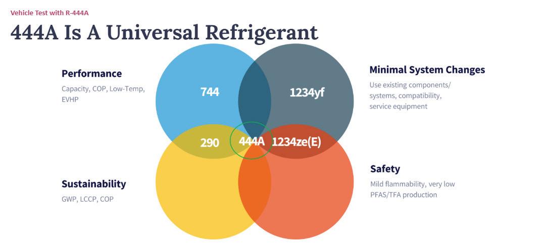
R-456A
Klea® 456A is a direct replacement for R-134a. Non-flammable and cost-competitive, R-456A has the same energy efficiency and cooling performance as R-134a with a much lower environmental impact (52% reduced GWP).
For servicing, shops may use either a certified R-134a or R-1234yf recovery machine to remove the existing refrigerant. Standard tools like vacuum pumps and refrigerant pressure gauge sets can be used to recharge the system, as can a new or upcycled machine programmed for R-456A or R-444A. The only required vehicle modifications are the use of refrigerantspecific fittings required by the EPA and a label denoting the new refrigerant. To learn more, scan this QR code.
Disclaimer: R-444A and R-456A are provisionally available pending final federal action under section 612 of the Clean Air Act. R-456A currently has provisional authorization for professional and DIY servicing, while R-444A currently has limited provisional authorization for professional servicing, with DIY authorization pending. EPA has proposed under SNAP Rule 27 to list both as acceptable, subject to use conditions, for MVAC professional and DIY servicing, with final action expected by mid-2026. Use conditions and other restrictions apply.

950 Winter Street, South Entrance 1st Floor























AUTOMOTIVE PRODUCT GUIDE
Display both primary and secondary parameters
The AUTOOL Digital LCR Tweezer, No. DM103, is a multifunctional portable LCR tweezer with a measurement accuracy of + or - 0.5%. It features a HD OLED color display and supports precise measurements of resistance, capacitance, inductance, and diode/continuity. It offers three testing frequencies: 100Hz, 1kHz, and 10kHz, with the option to choose between 0.3V or 0.6Vrms effective test levels. During measurement, it can synchronously display both primary and secondary parameters. The secondary parameters include RS, D, Q, Z, and X values meeting various component testing needs.
Ultra-thin 3.9mm inspection camera
Includes 14” screen and octa-core processor
The Articulating Borescope w/ Screen, No. MDSCOPE39SC, from Matco Tools is an ultra-thin 3.9mm inspection camera that articulates 180-degree in both directions to give technicians access to tight engine bays and confined service areas. It delivers precise visual inspection of narrow piping, small engine ports, and other cramped mechanical spaces that larger cameras can’t reach. The 5” High-Definition IPS screen and three adjustable brightness lights provide increased illumination so the user can identify cracks, corrosion, or blockages.
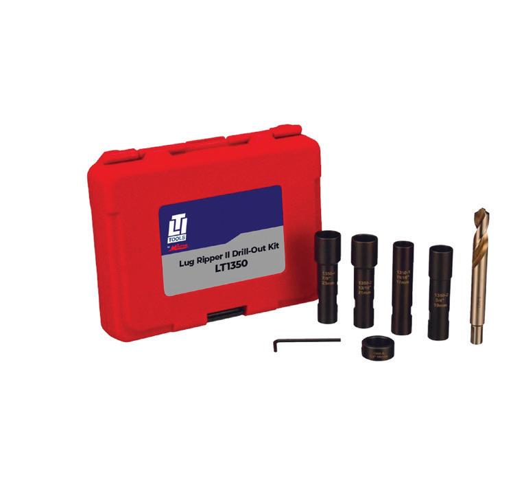
Four drill guides ensure accurate alignments
The Lug Ripper II Lug Nut Stud Drill Out Kit, No. LT140, from LTI Tools by Milton is designed to drill out lug nuts and studs in under 11 minutes with no torch needed. The 16mm cobalt step-up drill delivers faster, longer-lasting cuts, while the locking collar clamps keep the drill bit secure and rims protected. Four drill guides ensure accurate, error-free alignment. Blow-molded case keeps tools ready. Comes with four drill guides.
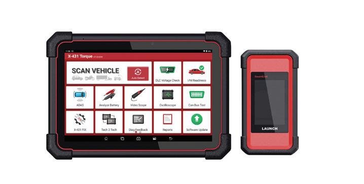
One tool. Every job. No limits.
From the shop floor to the fleet yard, the Launch Tech USA X-431 Torque AutoHD Pro scan tool is built to do it all. Whether you’re under the hood of a family SUV or beneath the chassis of a Class 8 diesel, it delivers full-spectrum diagnostics with precision and confidence. Light duty or heavy duty, gas or diesel—one connection, endless capability. Why switch tools when one can handle it all?
The Platinum 399 from Thinkcar features upgraded hardware that includes a 14” screen, an octa-core processor, a docking station, and a four-channel oscilloscope. Operations include high-speed scan with topology, read/clear code, graphing/ recording of live data, full bidirectional communication, and J2354 support for online programming. The new AI assistant accepts voice commands and provides access to common and troubleshooting tips. Coverage includes passenger cars and light trucks up to 1-ton capacity, with two years of software updates included. Electric vehicle coverage is included at no additional charge.
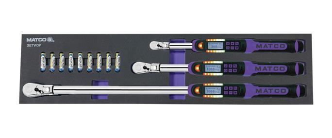
Now available in purple
The Matco Tools 3-pc Electronic Torque Wrench Set, No. SETW3P, is now available in purple. The set offers a 1/4” drive up to 20 ft-lbs, a 3/8” drive up to 100 ft-lbs, and 1/2” drive up to 300 ft-lbs, for wide torque range coverage across automotive jobs. Each wrench delivers + or - 2 % accuracy and reliable digital torque measurement on a clear LCD, so users can set and read values quickly. Users can switch between Nm, ft-lbs, and in-lbs, as needed, and rely on audible beeps and LED indicators to signal when the preset torque is reached, preventing over-tightening.
AUTOMOTIVE PRODUCT GUIDE
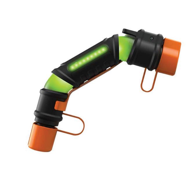
Prevents unintended EV movement
The Midtronics Electric Vehicle Immobilizer, No. xIM-100, can be used in situations where an electric vehicle may appear disabled but is still active. The xIM-100 provides clear, authoritative vehicle-status indication, and where supported, immobilization of BEVs and PHEVs through the universal charge-port interface. The tool helps to prevent unintended EV movement and offers instant visual confirmation of a secure connection—green for immobilized and red for caution. Users will have no direct contact with the high-voltage system, and its universal fit means it works in any charge port. The tool also maintains power for essential vehicle functions such as the windows, seats, and lights.
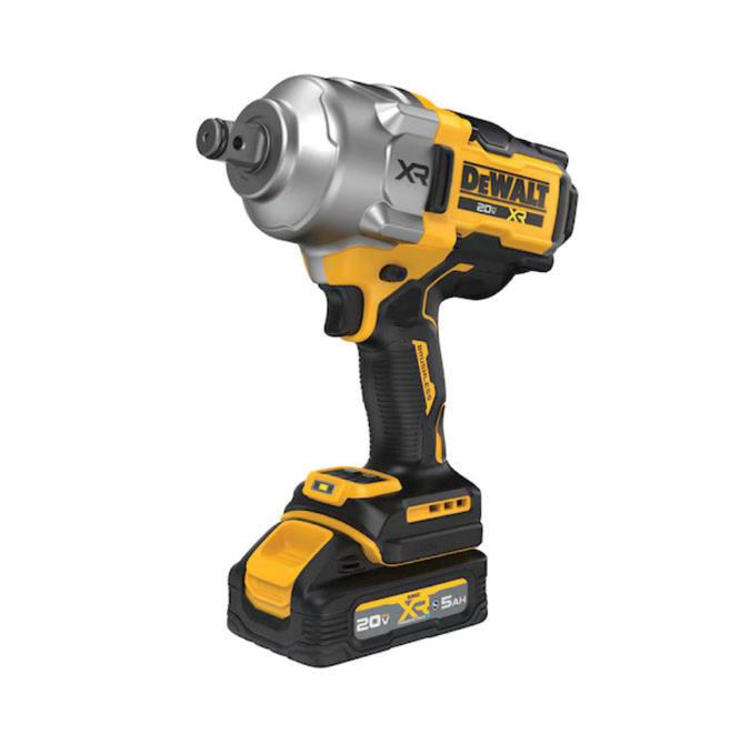
Features three speed settings
The 20V MAX XR 3/4” High Torque Impact Wrench with Hog Ring Anvil Kit, No. DWTDCF964GH1, from DeWalt, is designed to deliver 1,420 ft-lbs of max fastening torque and 1,900 ft-lbs of max breakaway torque— DeWalt’s highest-rated torque in its class. With up to 102% more torque, this tool is built for demanding applications. Three speed settings and Precision Wrench mode help prevent overtightening and fastener run-off, while the oil-resistant housing withstands harsh environments. The ontool LED worklight enhances visibility in dark spaces, ensuring maximum efficiency and productivity on any jobsite.
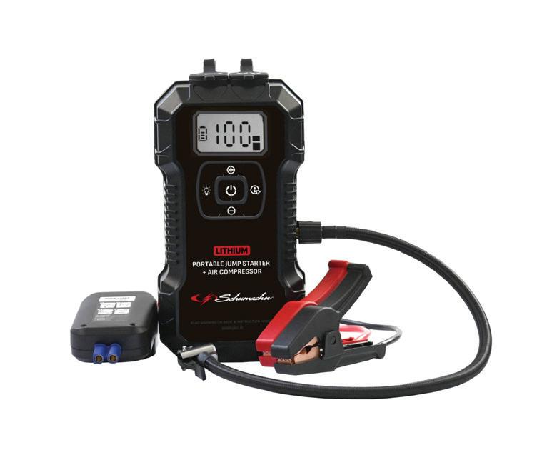
Delivers 1,800 peak amps for 12V jump starting
The Portable Jump Starter + Air Compressor, No. SL1686, from Schumacher Electric, is a compact, lithium-powered multi-function device designed for automotive, outdoor, and emergency use. It delivers 1,800 peak amps for 12V jump starting and features fast-charging USB-C and USB-A ports, a three-mode LED worklight (SOS, strobe, flashlight), and a high-efficiency air compressor with a maximum pressure of 150 psi. The compressor includes four inflation modes for cars, motorcycles, bicycles, sports balls, and a custom setting, with automatic shutoff at the preset pressure.

Ad Index














TECHNICAL SERVICE BULLETINS
COURTESY OF MITCHELL 1

TESLA AUTOSTEER UPDATE
This bulletin applies to 2012–2023 Tesla Model 3, Model S, Model X, and Model Y vehicles. On some vehicles, when Autosteer is engaged, the prominence and scope of the feature’s controls may not be sufficient to prevent driver misuse of this feature. If necessary, update the vehicle software to version 2023.44.30 or later.
(Photo Credit: Tesla)

FORD POSSIBLE FAULTY POWER ASSIST
This bulletin applies to certain 2018–2023 Ford Mustang vehicles that were repaired with a service replacement electronic power steering assist (EPAS) gear and
may have the secondary digital torque sensor in the steering gear calibrated with an inverted polarity. If the primary steering torque sensor experiences a failure or fault, the inverted polarity on the secondary sensor may cause the steering wheel to begin oscillating without warning when attempting to steer, due to the EPAS providing unintended steering assist. The dealership may have either installed an affected EPAS steering gear or sold the gear over the counter as a replacement. Reprogram the PSCM (power steering control module).
(Photo Credit: Ford)

MINI
COLOR CHANGE
This bulletin applies to 2020 Mini vehicles. The ambient lighting may change color after the vehicle goes to sleep. The cause: a short-term bus fault. To correct, perform a BDC (body domain controller) reset. 1. Read out the vehicle using ISTA.
2. Perform the BDC reset using ISTA.
3. Let the vehicle go to sleep and verify the repair.
(Photo Credit: Mini)



This bulletin applies to 2018–2025 Alfa Romeo Stelvio and Giulia vehicles. The oil change light may illuminate within 4,000 miles as a result of being parked for an extended time.
1. Perform an engine oil and filter change.
2. Reset the oil change indicator system. Without pushing on the brake pedal, push the engine start/stop button and cycle the ignition to ON/RUN position (do not start the engine). Fully depress the accelerator pedal, slowly, five times within 10 seconds.
3. Without pushing the brake pedal, push the engine start/stop button once to return the ignition to the OFF/ LOCK position.



ALFA ROMEO OIL CHANGE RESET

by BendPak
APEX by BendPak delivers dependable wheel service performance built for daily shop use, with tire changers that provide consistent clamping, smooth bead breaking, and controlled operation, paired with wheel balancers engineered for accurate, repeatable measurements and fast cycle times. Every APEX wheel service machine is designed for stability, precision, and durability, giving technicians reliable results vehicle after vehicle without unnecessary complexity or wasted features.