
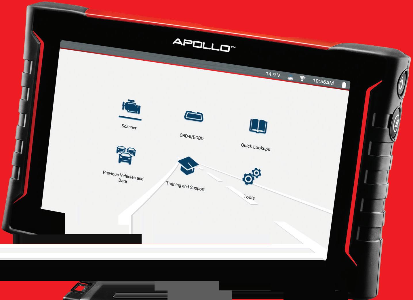
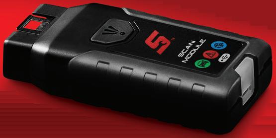


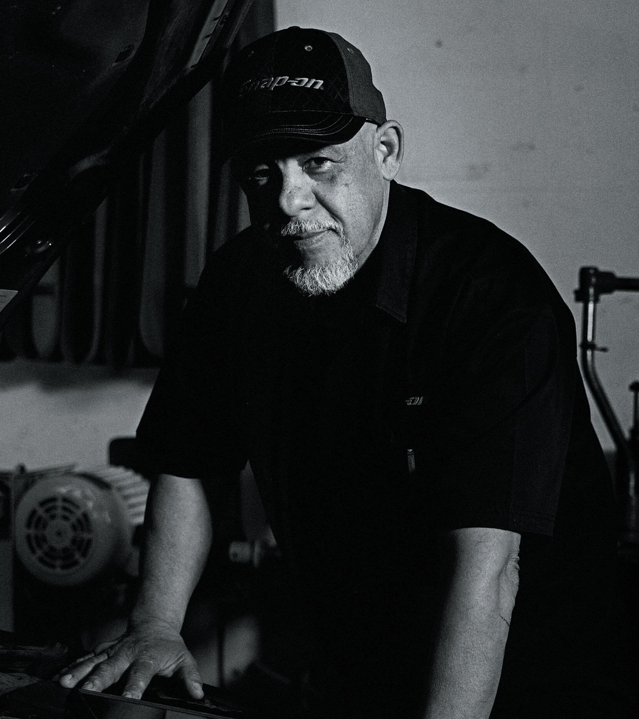













Stronger in numbers. Add yourself to the equation. Miguel isn’t one to ask for help. Equipped with The TRITON™, which provides verified fixes harvested from users across the globe, he doesn’t have to. Offering a 2-channel lab scope and wireless connection, it’s like having 70 thousand techs, each with 40 years of experience at his side. So you can cover Miguel’s back, and he’ll cover yours. Plus up your numbers with the diagnostics system that adds you to the equation.


Amp up your inventory. Motorcraft® parts are premium replacement parts designed, engineered and recommended for Ford and Lincoln vehicles. They’re tested to provide performance and long-life reliability. And they’re 20,000 active parts strong, with a deep inventory that includes batteries, wiper blades, brakes, spark plugs and much more. Easy – for you and your customers. See your Ford Certified Parts Wholesale dealer for details.

18 Business in the Front, Party in the Rear Shop revenue is a team sport—and when communication, documentation, and diagnostics don’t align, you lose money and customer trust.
Brandon Steckler
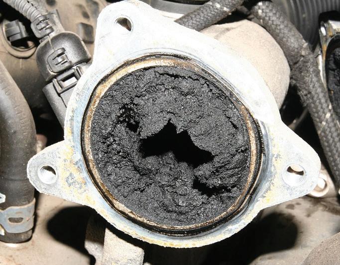
28 Modern EGR: A Fully Integrated Strategy
From vacuum valves to VVT-driven internal flow, today’s EGR touches every aspect of engine operation.
Erik Screeden
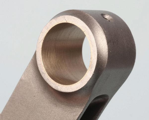
38 Piston and Rod Orientation: Get It Right or Pay for It Later
From rod chamfers and bearing tangs to asymmetric skirts and offset wrist pins, here’s what every engine assembler should verify before torquing the cap.
Mike Mavrigian
48 Diagnosing Today’s 4WD and AWD Systems
How they work, how they fail, and why software, calibration, and tire condition now matter as much as the transfer case itself.
Jeff Taylor
54 The Customer-Supplied Parts Dilemma
Customers walk in with a box and ask you to install it. Here’s how that quietly drains margins—and what top shops do differently.
Noah Nelson
62 Ultrasonic Inspection for Wall Thickness
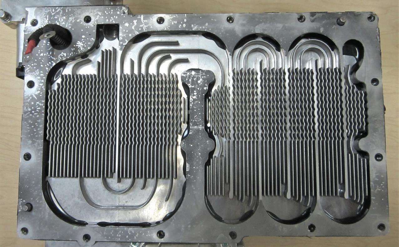
From battery cooling to cabin insulation, thermal management is becoming one of the most critical technologies shaping the future of electric vehicles.
Craig Van Batenburg
68 Automotive Product Guide
72 Technical Service Bulletins
72 Ad Index
Motor Age is published 6 times yearly (February, April, June, August, October, December) by Endeavor Business Media, LLC. 201 N Main St 5th Floor, Fort Atkinson, WI 53538. Customer service can be reached toll-free at 877-382-9187 or at MotorAge@omeda.com for magazine subscription assistance or questions. Printed in the USA. Copyright 2026 Endeavor Business Media, LLC. All rights reserved. No part of this publication may be reproduced or transmitted in any form or by any means, electronic or mechanical, including photocopies, recordings, or any information storage or retrieval system without permission from the publisher. Endeavor Business Media, LLC does not assume and hereby disclaims any liability to any person or company for any loss or damage caused by errors or omissions in the material herein, regardless of whether such errors result from negligence, accident, or any other cause whatsoever. The views and opinions in the articles herein are not to be taken as official expressions of the publishers, unless so stated. The publishers do not warrant either expressly or by implication, the factual accuracy of the articles herein, nor do they so warrant any views or opinions by the authors of said articles.
Endeavor Business Media provides certain customer contact data (such as customers’ names, addresses, phone numbers, and e-mail addresses) to third parties who wish to promote relevant products, services, and other opportunities that may be of interest to you. If you do not want Endeavor Business Media to make your contact information available to third parties for marketing purposes, simply call toll-free 877382-9187 or email MotorAge@omeda.com and a customer service representative will assist you in removing your name from Endeavor Business Media’s lists.
Motor Age does not verify any claims or other information appearing in any of the advertisements contained in the publication, and cannot take responsibility for any losses or other damages incurred by readers in reliance of such content. While every precaution is taken to ensure the accuracy of the ad index, its correctness cannot be guaranteed, and the publisher waives all responsibility for errors and omissions

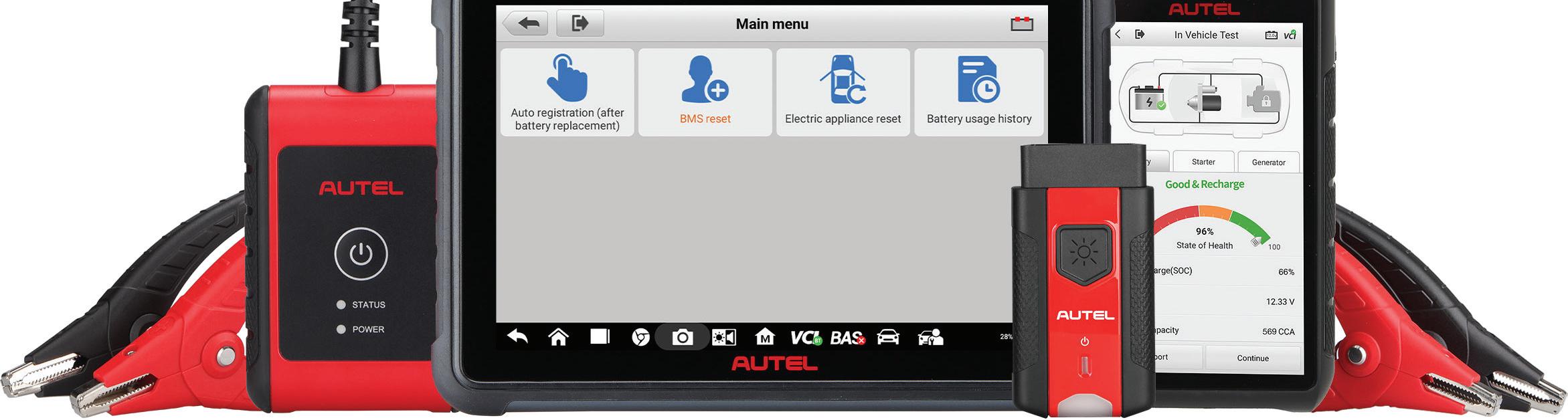
In this hands-on walkthrough, Keith Perkins of Motor Age diagnoses a network communication fault on a 2017 Honda Civic, where the VSA modulator—Honda’s ABS module—fails to communicate after recent repairs.
Using the Autel MaxiSYS Ultra S2, Perkins moves from initial scan and topology mapping to pinpoint testing and final validation. The video covers CAN bus troubleshooting, showing how to interpret network data and isolate the root cause.
The culprit: connector pin tension—an easy-to-miss detail that can disrupt system communication. The repair restores proper function and reinforces the value of a structured diagnostic approach.
Watch the full walkthrough for practical insights you can apply in the bay.

Every f lat-rate tech knows the frustration: playing “guess the noise,” chasing a vague symptom that burns up your morning, doing the service advisor’s job for free. Turning wrenches pays the bills—but you can’t make money volunteering your time at the front counter.
In this episode of Technician Level Up, we stop treating communication like extra paperwork and start using it as a precision tool to protect your workflow. The real money is made before you ever walk out to the car.
We break down the “customer interrogation”—the five essential pieces of evidence you need from the front desk to make every minute in your bay billable.

EDITORIAL
GROUP EDITORIAL DIRECTOR
Chris Jones / christopherj@endeavorb2b.com
EDITOR
Mike Mavrigian / mmavrigian@endeavorb2b.com
TECHNICAL AND MULTIMEDIA CONTENT DIRECTOR
Erik Screeden / escreeden@endeavorb2b.com
TECHNICAL EDITOR
Noah Nelson / nnelson@endeavorb2b.com
CONTRIBUTING WRITERS
Jeff Taylor, Craig Van Batenburg, Brandon Steckler
ART AND PRODUCTION
ART DIRECTOR
Emme Osmonson
PRODUCTION MANAGER
Sheila Ward
AD SERVICES MANAGER
Karen Runion
SALES
ASSOCIATE SALES DIRECTOR
Mattie Gorman-Greuel / mgorman@endeavorb2b.com
DIRECTOR OF BUSINESS DEVELOPMENT
Cortni Jones / cjones@endeavorb2b.com
ACCOUNT EXECUTIVES
Kyle Shaw / kshaw@endeavorb2b.com
Marianne Dyal / mdyal@endeavorb2b.com
Darrell Bruggink / dbruggink@endeavorb2b.com
Sean Thornton / sthornton@endeavorb2b.com
Diane Johnston / djohnston@endeavorb2b.com
Lisa Mend / lmend@endeavorb2b.com
Chad Hjellming / chjellming@endeavorb2b.com
ENDEAVOR BUSINESS MEDIA, LLC
CEO Chris Ferrell
COO Patrick Rains
CDO
Jacquie Niemiec
CALO
Tracy Kane
CMO
Amanda Landsaw
EVP TRANSPORTATION
Chris Messer
EVP ENDEAVOR BUSINESS INTELLIGENCE
Paul Mattioli
VP OF CONTENT STRATEGY, TRANSPORTATION GROUP
Josh Fisher
BUSINESS STAFF
PUBLISHER
Andrew Johnson
BUSINESS DEVELOPMENT DIRECTOR, MOTOR AGE TRAINING
Michael Willins
HOW TO REACH US
ENDEAVOR BUSINESS MEDIA LLC.
30 Burton Hills Blvd, Ste. 185, Nashville, TN 37215 Phone: 800-547-7377
CUSTOMER SERVICE
Subscription Customer Service 877-382-9187; 847-559-7598
MotorAge@omeda.com PO Box 3257 Northbrook, IL 60065-3257
REPRINT SERVICES reprints@endeavorb2b.com
MEMBER OF:













of the extensive support I receive as a local independent shop owner. This support gives our customers access to shops across the country and ensures they will have peace of mind wherever they travel. Ó




JOHN WADE
Super Eagle Auto Care
TechNet Member Since 2014















































Level up your shop and get access to exclusive business and marketing solutions, including motorist programs like Nationwide Warranty, Roadside Assistance and Road Hazard Tire Protection.





Scan the QR code or visit technetprofessional.com/membership to learn more.
MANY OF US OWN SMARTPHONES, taking still photos or video recordings is commonplace and easy (so easy, even I can do it).
During vehicle inspection or diagnosis—during a repair or after a repair is done—many techs take snapshots for their own use to remind them of a belt routing, evidence of a missing bolt, evidence of a rotted subframe that prevents a simple control arm replacement, etc. Consider taking shots or videos you can send to the customer. Many shops and dealerships are doing just that. For instance, when a vehicle is on a lift during an oil change, do a simple walk-around, perhaps verbally noting that the belly looks clean, the exhaust looks great (or has a problem), and brake pad thickness (which is good or needs replacement). You get the drift. It gives the customer—who has never seen a glimpse of the underside—an eye-opener regarding the condition, whether good or bad.
People like watching videos. When everything looks great, this puts the customer at ease and hopefully results in a warm and fuzzy feeling. When things are bad and require service, customers gain a better understanding as opposed to simply being told that certain work needs to be done.
The idea of taking photos or videos isn’t new, but in addition to recording for
your own reference, consider a steady practice of making these visual and au dio-visual recordings specifically for the customer.
The editorial staff at Motor Age strives to provide valuable tech information that actually helps you do your job. We’re ded icated to that goal, and we strive to be more than “just another magazine” that offers bathroom-break reading. This isn’t marketing hype—we’re serious about providing the best useful information to help our readers understand a variety of systems, perform a task properly, and maximize shop profits.
Toward that end, we honestly want your input. If you want certain topics covered, let us know. From info that helps newbie techs learn the basics to advanced technicians who want more information, we’re here to do just that. By “advanced,” we don’t limit that to only focusing on computer diagnostics. Add to that helpful info regarding hands-on, wrench-in-hand service procedures involving engines, transmissions, braking systems, steering and suspension, and everything in between.
We listen to readers. You’re the folks in the trenches. It’s common for skilled technicians to develop tricks and tips involving certain repairs. Let’s share those




MIKE MAVRIGIAN MOTOR AGE // EDITOR mmavrigian@endeavorb2b.com








































































As the automotive service industry faces rising costs, supply constraints, and stricter environmental requirements, technicians are asking: Is there a realistic replacement to R-1234yf that works in today’s systems without significant system changes or ways of working? Finally, the answer is yes: Orbia’s R-444A.
Developed using commercially available HFO and HFC components, R-444A is intentionally formulated to be a direct replacement for R-1234yf while performing like R-134a. Technicians can use standard YF procedures and equipment, recharge with similar charge amounts, and use them in existing systems (compressors and heat exchangers).
The top priority for most shops is customer satisfaction. The improved cooling capacity of R-444A means that the customer’s AC system will deliver cold air faster to the cabin, enabling enhanced customer comfort and satisfaction, promoting repeat business.
Shops also raise concerns about cost. R-444A offers a cost competitive alternative to R-1234yf. It is a blend made from well-established refrigerant components produced by multiple manufacturers, providing supply chain flexibility and a different cost structure.
R-444A improves both cooling capacity and energy efficiency, reducing compressor power that can translate into an improved fuel economy. This improved efficiency may also extend the driving range of EVs and vehicles with heat pump systems. From a service standpoint, R-444A fits into existing R-1234yf workflows. Technicians recover the original refrigerant, evacuate the system, leak check under pressure, and recharge with a similar charge amount. Current PAG or POE oils used with R-1234yf are fully compatible, and oil circulation is actually improved due to overall better solubility and miscibility. Better oil return supports compressor durability and long term system reliability, adding value for both shops and customers.
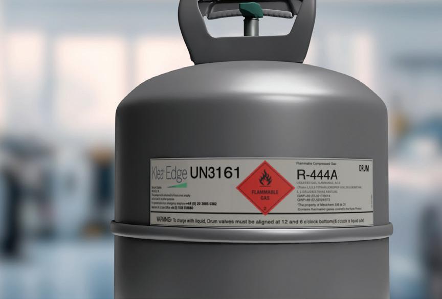
Leak detection and diagnostics also remain unchanged. Standard SAE J2913 leak detectors, currently used with R-1234yf, can be used with R-444A. UV dyes approved for YF systems are likewise compatible. Operating pressures are very similar to YF, with only marginal differences that fall well within existing service expectations.
Environmental performance is another area where R-444A addresses growing concerns. With a GWP under 150, R-444A meets current regulatory targets while deliver ing higher system performance, and lower lifecycle carbon emissions than R-1234yf.
It’s important to note that “direct replacement” does not mean “top off” of an existent R-1234yf system. Proper recovery of R-1234yf is required as mixing refrigerant in the system is not recommended. Recovery machines must be dedicated and clearly labeled when handling multiple re frigerants, and SAE is actively finalizing standards for port adaptors and other handling requirements. Like R-1234yf, R-444A is classified as A2L (mildly flammable), so existing safety practices apply.
For shops looking ahead, R-444A offers a rare combina tion for differentiated service: lower cost*, better perfor mance, no issues with polymerization, and compatibility compared with today’s R-1234yf equipment. These bene fits make the adoption of R-444A a logical conclusion, as it creates happier customers while building trust. Orbia’s R-444A is the ideal replacement for R-1234yf that can keep customers happy and improve the bottom line.
*Based on market data from May 2026.
Disclaimer: R-444A is provisionally available pending final federal action under section 612 of the Clean Air Act. R-444A currently has limited provisional authorization for profes sional servicing, with DIY authorization pending. EPA has proposed under SNAP Rule 27 to list R-444A as acceptable, subject to use conditions, for MVAC professional and DIY servicing, with final action expected by mid-2026. Use condi tions and other restrictions apply.












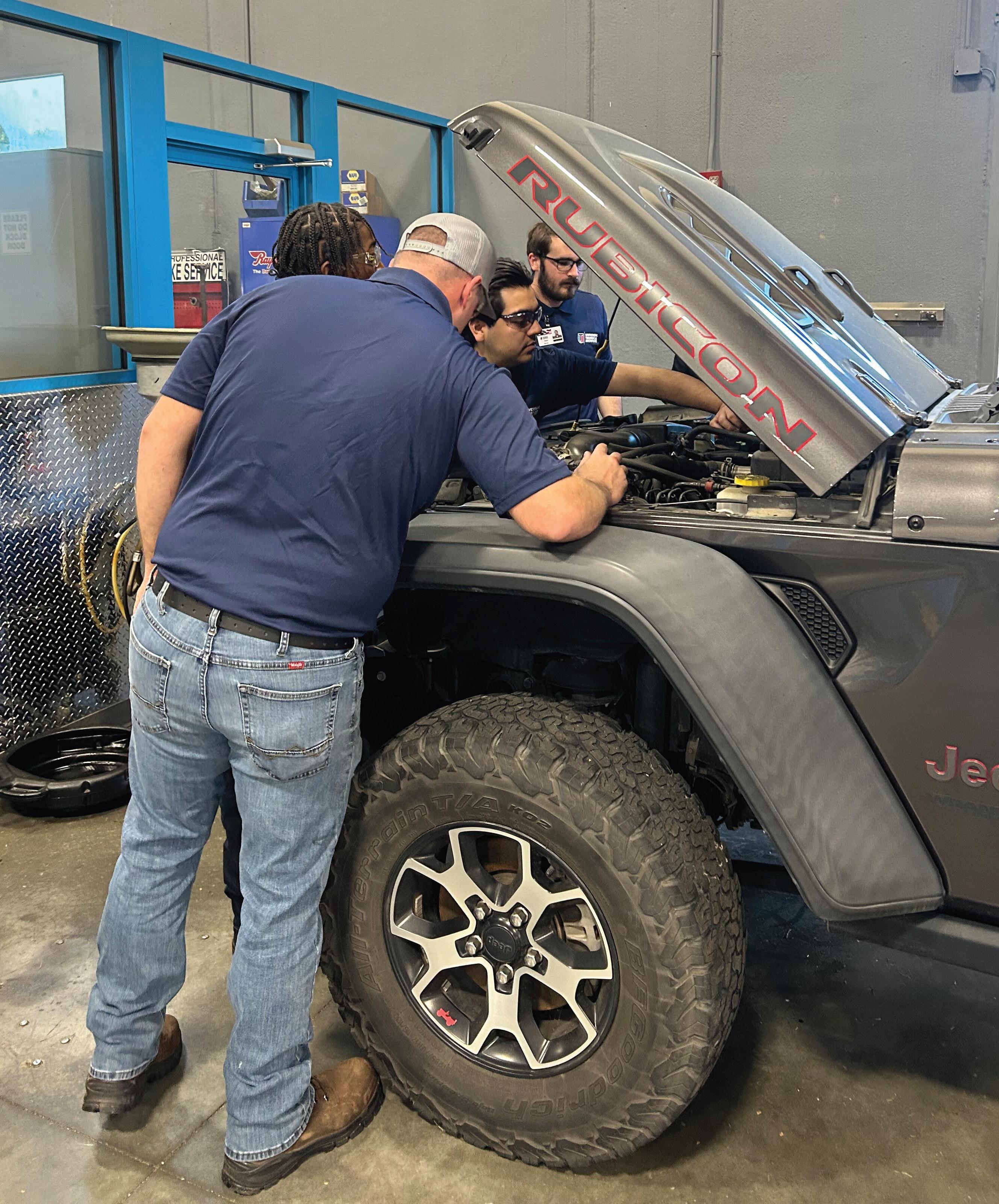
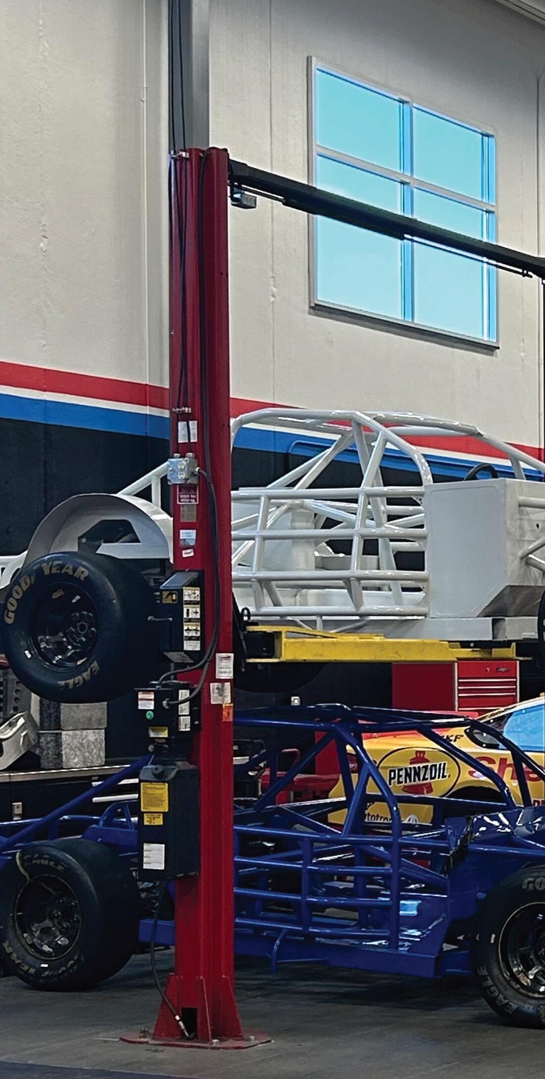
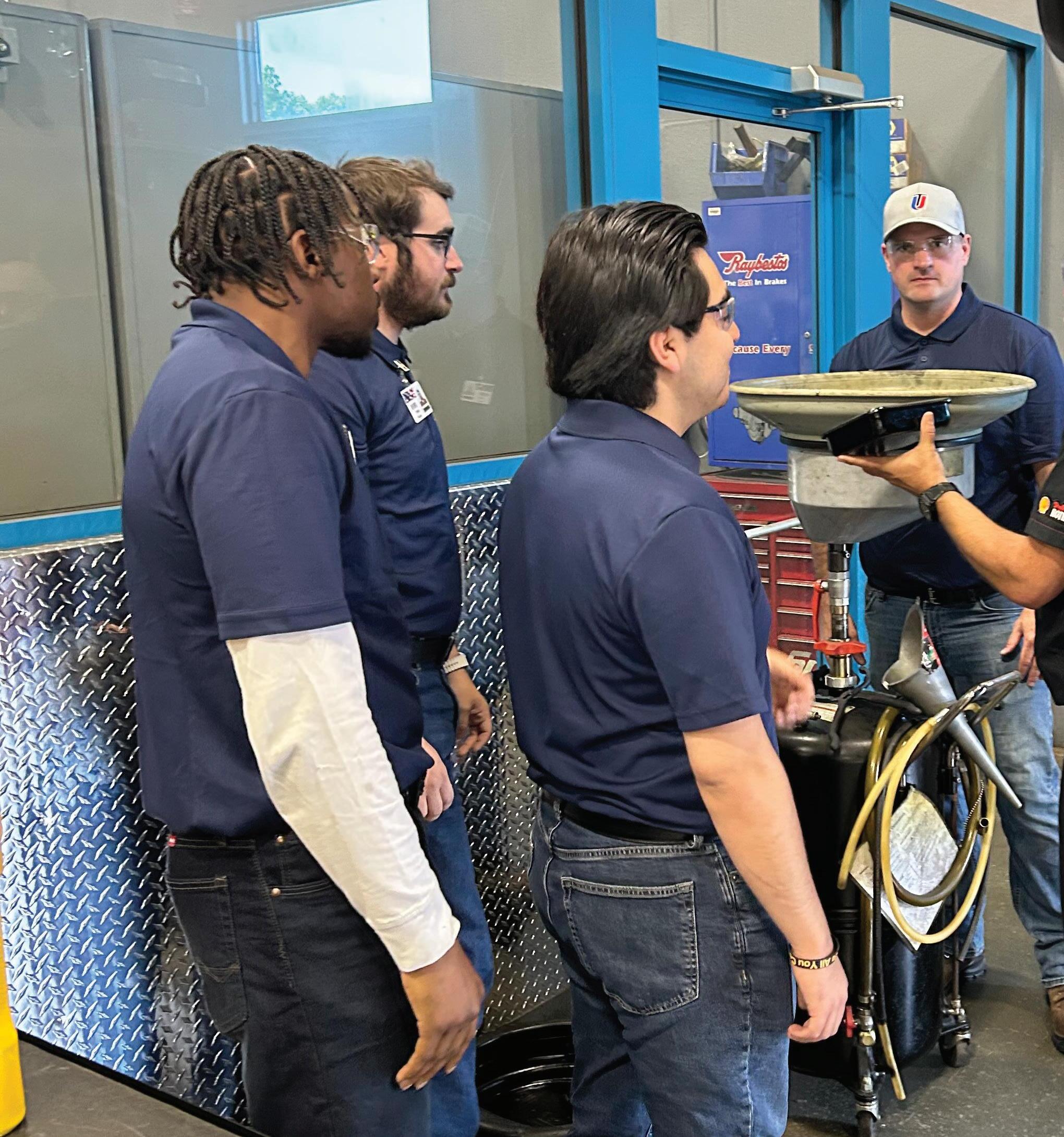
AT THE UNIVERSAL TECHNICAL INSTITUTE campus in Mooresville, North Carolina, 35 dealerships, trucking companies, and recruiters lined the parking lot with pop-up tents under blue skies at the bi-annual career fair. In an unusual twist, the students have the upper hand. Although
BY








they’re searching for employment, their demand in the industry gives them an advantage. Instead of trying to convince a prospective employer to choose them, the employers are actually the ones competing for the best talent.
Across the country, dealerships and independent repair shops are all chasing the same thing: entry-level technicians who can contribute quickly. UTI graduates have that competitive edge based on their experience.
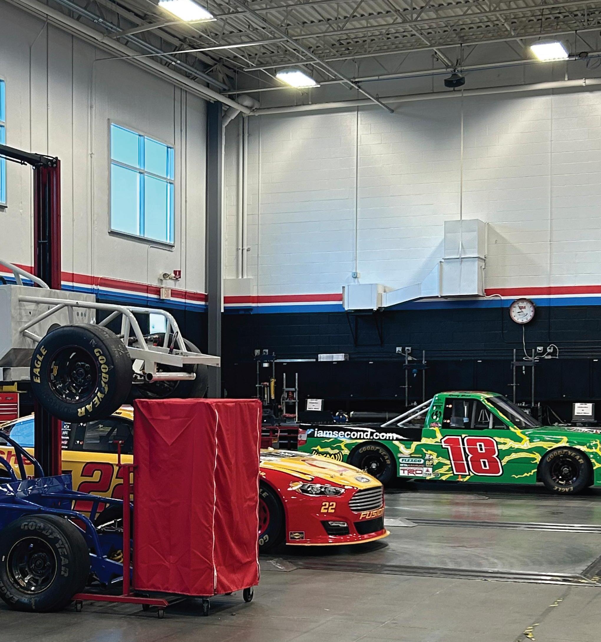
The Universal Technical InstituteMooresville offers six core programs, including Automotive & EV Technology, Welding Technology, HVACR Technician, Electrical & Industrial Maintenance Technology, Electrical, Electronics & Industrial Technology, Electrical, and Robotics & Automation Technology. Plus, Mooresville offers NASCAR-endorsed training and manufacturer-specific advanced training options for automotive graduates, including Ford FACT and Mopar TEC.
The team manages 90-plus brand relationships across UTI campuses nationwide, including brands like Pennzoil, HarleyDavidson, Peterbilt, Kawasaki, Ford, Honda, Jeep, GMC, Mercedes, and Suzuki. The focus is on helping companies engage, recruit, and/ or support the next generation of aspiring technicians through product and training-aid inclusion, digital promotion (UTI Go), campus presence and branding, and oncampus engagement.
UTI operates 16 campuses across 10 states with additional new campuses planned, such as UTI–Salt Lake City in West Jordan, Utah, which is slated for opening in 2027.
As Robert Kessler, campus director, puts it, “These employers, usually they come in and tell us, ‘I don’t need one. I need, like, three or four guys. Can you help us?’”
That demand shapes everything happening inside UTI’s classrooms and labs. The goal isn’t simply graduation—it’s producing technicians who are ready for the realities of today’s shop environment.
John Dodson, vice president of business alliances, says the pressure is constant. “There are three available for every student,” he notes.
For shop owners and working technicians, the bigger question isn’t whether students are interested in the field—it’s whether those students are actually prepared to hit the ground running in the shop.
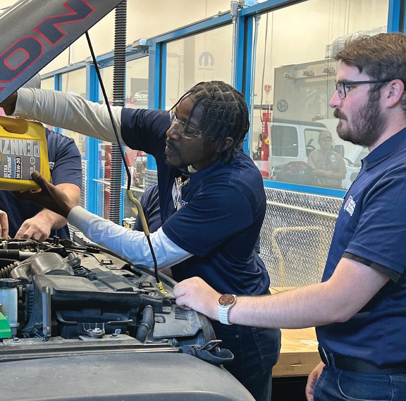
While oil changes may still be viewed as
I’M
—Isaac Hales , student
the entry point for many new technicians, the skill shops want most today is electrical diagnostics, says Bobby Leatherman, education manager at UTI-Mooresville.
“Right now, the more electrical, the better,” he asserts. “If a student comes in and takes electrical classes and does well in them, they can pretty much get a



job anywhere.” Although today’s technicians are expected to navigate increasingly complex electrical systems, onboard computers, and advanced diagnostics, there’s still something to be said for basic diagnostic skills.
Even with diagnostics taking center stage, UTI has intentionally gone back to basics. Tony Frassetto, director of business alliances, says employer and advisory board feedback encouraged the school to refocus on foundational work.
“They’ve asked for us to sort of go back to the basics, back to oil changes,” he notes. It may sound simple, but it reflects how most careers in the shop actually begin.
“They’re not going to leave here at 20 years old and be turned loose in a garage,” Dodson points out. “They’ll either go on to BMW or Mercedes, or they’ll go to a garage, and they’ll start out in the quick lane, and they’ll move their way up.”
For employers, that matters. Shops don’t need entry-level technicians pretending to be master techs—they need new hires who understand the fundamentals, perform them correctly, and earn the next opportunity.
Technical skills may get a student noticed, but professionalism often determines whether they get hired—and whether they stay.
Dodson says UTI places heavy emphasis on workplace expectations.
“Are you on time? Are you a professional? Do you have your work shoes, your safety glasses, your name tags?” he asks as part of the typical checklist for students.
Those details matter because employers are evaluating more than wrench skills. Attendance, attitude, and communication often decide who gets promoted from quick lane to diagnostic work.
Kessler says career preparation is built into the curriculum from day one.
“We do mock interviews with them, we
do resume prep,” he explains. “Everything we do, in addition to the curriculum, is all aimed at getting them into a job.”
For technicians already in the field, this may sound basic—but for the next generation entering the industry, these expectations are often new. And while some technicians have a natural talent when it comes to being conversational, not all are blessed with the gift of gab.
Hiring young technicians today requires more than posting an opening and waiting. Frassetto says the best employers build a long-term plan.
“Bring them in with a plan for growth, you know, put them under a master technician or someone who’s sort of like their mentor,” he encourages shop owners and leaders. That mentorship piece is critical, especially for independent shops and quick lube operators competing against dealerships with large incentive packages.
Margie Decker, director of student and career services, says visibility matters. “I think showing a pathway so that they have
a clear understanding is important,” she says. “Most of our students are taking those jobs as part-time jobs right now while they’re in school—they’re not thinking of them as long-term careers. And when you have an organization that can build and incentivize those individuals to stay, whether they become an owner of a franchise or what they do with it, that’s the ticket.”
Student Isaac Hales may be the best example of what employers hope to find. He drives two hours each way to campus every day, chasing a future in high-performance and motorsports work. UTI-Mooresville is the only campus that also offers NASCAR-endorsed mechanical training.
When asked what he’s taking with him after graduation, his answer was immediate: “Precision under pressure is the biggest thing that I’m taking away,” he asserts.
He’s already thinking beyond the first job.
“I’m looking for something that gives
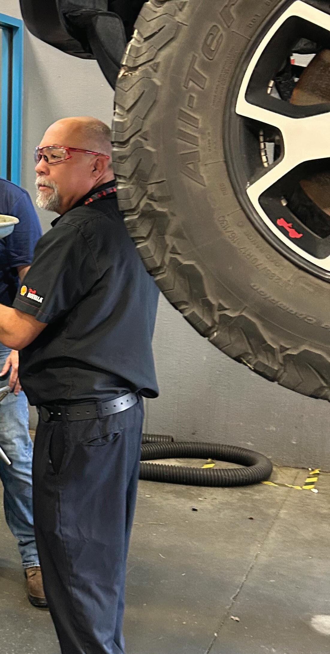
... WHEN YOU HAVE AN ORGANIZATION THAT CAN BUILD AND INCENTIVIZE THOSE INDIVIDUALS TO STAY, WHETHER THEY BECOME AN OWNER OF A FRANCHISE OR WHAT THEY DO WITH IT, THAT’S THE TICKET.”
—Margie
director of student and career services
me the opportunity to work on high-performance vehicles or things that have character to me,” he explains.
That mindset is exactly what shops need: technicians who understand that the first job is only the beginning.
The technician shortage won’t be
solved by simply graduating more students. It’ll be solved by producing entry-level technicians who can walk into a shop, learn quickly, and grow.
That’s the real challenge for the industry—and the one schools like UTI are trying to address.





When you purchase a new crankshaft for an engine that features a rearmounted toothed tone wheel (also called a reluctor wheel)—such as found on a GM LS-format crankshaft—the new crank may or may not include an installed reluctor wheel. If the wheel is provided with the crank but not installed, or if you need to purchase a wheel, be aware that the installation process is critical. The reluctor wheel (also called a tone wheel) is intended to press fit to the rear of the rear counterweight with about a 0.007-inch press fit. This requires heating the wheel to allow a smooth installation. Never attempt to force the wheel into place with a hammer; this will distort the wheel. You also need a special tool that allows you to properly index the wheel clock position and to draw the wheel into place. (Goodson, for example, offers tool RRJ-350.)
The jig tool is comprised of a short steel tube that’s equipped with two indexing pins. An external tang secures a
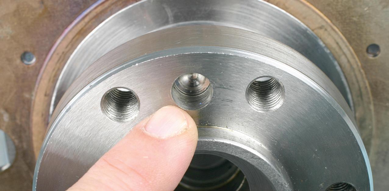
threaded stud, with the stud tip turned down to 8 mm diameter. This pin engages with the single 8 mm indexing hole in the reluctor wheel. The tool’s internal guide pin engages the 11 mm blind dowel hole in the crank’s flywheel flange. The jig tool orients the reluctor wheel precisely in the correct timing position. The two dowel studs feature jam nuts to allow depth adjustment. Lightly chamfer the entry hole of the reluctor wheel, and lightly chamfer the outer edge of the crank’s reluctor wheel flange. Heating the wheel to
A truck that features a two-piece driveshaft will feature a carrier bearing. If the carrier bearing wears out, and/or the U-joint behind it starts to seize up, the customer is likely to complain about a droning
noise that sounds like the vehicle is being driven over a road surface that has just been graded. It isn’t uncommon for someone to first suspect the transmission. Check the carrier bearing and driveshaft U-joints first
about 450 degrees Fahrenheit expands the center hole slightly to allow a smooth press fit.
Once the wheel has been installed and allowed to cool, test-fit the crankshaft into the block and carefully inspect to verify that the wheel won’t come into contact with the rear main cap area. Check to make sure that the wheel features no discernible runout, and make sure that it’s aligned with the crankshaft position sensor, which is located at the rear of the left side of the block.
and save yourself a bunch of time and aggravation. Also, be aware that there are several different part numbers of carrier bearings for the Ford trucks, so save the original for a match-up.
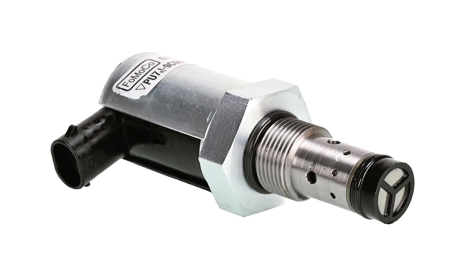
If the owner of a Ford F-Super Duty diesel truck complains about intermittent surging and engine shutoff after accelerating from a dead stop, a possible cause is the injector high-pressure relay valve. Even if the valve is good, if the valve mounting isn’t tightened properly, it can cause the magnet inside to move upon acceleration, signaling the engine to shut off. Make sure the valve is secured properly.
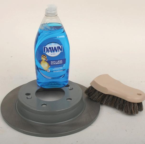
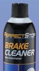
Before installing any new or used brake rotor, the rotor disc surfaces need to be as clean as possible. New rotors are often shipped with an anti-rust agent to prevent surface rusting while in storage. While using a spray brake cleaning solvent may seem convenient, this may not remove all surface deposits, such as grease or preservative wax materials. A better cleaning method involves
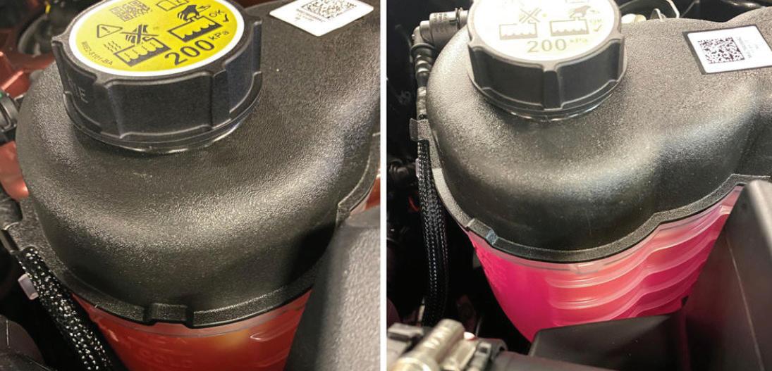
JUST A TIP: Jaguar recently changed the type of coolant used for all Jaguar vehicles. Jaguar Land Rover has updated the coolant from Havoline XLC to Arteco Freecor FTC. Havoline XLC is orange, while the Freecor FTC is red.
hot water and specifically Dawn dishwashing liquid (Dawn liquid, not Dawn spray foam). This cleaning agent does a great job of cleaning the microscopic pores and machining scratches. Scrub with Dawn and really hot water, then rinse in hot water and dry. The pads will mate to the disc surfaces better, with better transfer of pad material to the disc surfaces.
Generating revenue in an automotive shop is a team sport—and if your communication, documentation, and diagnostic structure aren’t aligned, you’re leaving money (and customer trust) on the table
BY BRANDON STECKLER


WHEN THE AVERAGE PERSON ENVISIONS THE OPERATION OF AN AUTOMOTIVE REPAIR SHOP, they’re likely thinking about the technicians. Of course, a shop can’t exist without the service-technical staff, but it also can’t survive without the rest of the team—ideally, like a welloiled machine.
This includes leadership; a foreman, if you will. Although this role is defined differently from shop to shop, foremen generally play a role in distributing work, continuing education for the rest of the technicians, and are the last line of defense for problem-child vehicles, avoiding negative shop experiences like misdiagnosis and “comebacks.” More often than not, this same person becomes the liaison between the rest of the techs and the service advisors—and even the customers in some circumstances—often handling bottlenecks as they surface.
Having someone in that role is a prudent way to structure how a shop operates because of the built-in fail-safes mentioned above. However, I feel many techs and advisors (and other customer-facing team members) rely too heavily on this structure, and as a result, the foreman is stretched too thin and all of the situations requiring his or her input are delayed. Believe it or not, I feel there’s a bigger underlying issue. This structure tends to make techs lazy, and that’s bad for business; lost revenue is just the beginning.
What I’m describing above isn’t a comment that has been shot from the hip. I’ve witnessed this happen in shops all across the country. And here’s where the main issue lies, in my opinion.
Technicians fall prey to the flat-rate pay structure and tend to cut corners. No, I’m not only speaking about taking shortcuts in the repair process, necessarily, but I am speaking about how the repair orders are documented. Let’s face it: the less time spent putting pen to paper (or populating a digitized document), the
more effective time can be spent making money on other jobs. (Yes, this also occurs in shops without the flat-rate pay scale.)
But here’s what many techs and other team members don’t take the time to consider:
• For every moment a service advisor must trudge back into the shop to get more information from a technician, that’s less effectively applied time the service advisor is producing revenue (answering the phone, scheduling appointments, and selling work).
• This same transaction costs the technician effectively applied time as well, for obvious reasons. They must stop working to answer pertinent questions.
• The missing information from the repair order costs the technician (and the shop) money, as many times, certain labor operations have been inadvertently omit-
ted. The work has been completed, but neither the technician nor the shop has collected for these operations (such as programming and configuring an ECU after replacement).
• Consider when an undocumented underlying or additional issue exists on the vehicle. The customer returns for a subsequent visit under the impression that the issue will be rectified free of charge (often already frustrated with the shop). From the shop’s perspective, you don’t have a leg to stand on. Had the repair order been documented properly— noting the vehicle’s existing status or area of concern—at worst, you could’ve said, “I told you so.” At best, you could’ve further solidified your rapport with the customer as an honest and thorough facility, looking out for their best interests.
• Repair orders become legal documents in situations when we find ourselves
in a court of law. Needless to say, if the document won’t hold water, we may be responsible, and the cost may be a lot more than just money.
• And last, but certainly not least: justifying additional diagnostic time. It’s hard enough for some shops to get paid for any type of diagnostics (that’s a problem they need to focus on, but it’s outside the scope of this article). But asking for more money after quoting perhaps one hour of initial diagnostic charge can be like pulling teeth, especially if the advisor doesn’t understand the specific reason.
• I’m sure you get my point by now. We need to be doing a better job at documenting. That goes for what the technician documents on the repair order, but also what the service advisor includes on the documentation issued back to the customer for their records. More importantly, we need to be



















































































doing a better job at communication in general. This goes well above and beyond the traditional “3 Cs”— complaint, cause, and correction.
A 2010 Cadillac Escalade was towed to the shop with the complaint that the transmission wasn’t performing correctly:
• The customer experiences a harsh shift into gear.
• The shift indicator (the PRNDL) was inoperative.
• The engine RPMs were elevated before the vehicle would move, and was slow to accelerate.
• The MIL was also illuminated.
The customer was quoted an initial one hour of diagnostic time to evaluate the concern. The customer agreed to the charge, and analysis proceeded. A scan for DTCs was performed, and among other issues, no communication with the vehicle’s transmission control module could be established.
An initial preliminary inspection revealed an open fuse No.19, located in the under-hood fuse block. The technician attempted to replace the overloaded fuse, but the fuse would open subsequently. At this point, he reached out to me for assistance.
Approaching the situation with not only an urge to provide a diagnosis, but also as an educational opportunity, I began discussing with the technician what the indication of the blown fuse signifies. We discussed the circuit’s current flow exceeding the fuse rating. And, if this fuse was the correctly rated fuse for the suspect circuit, the circuit was overloaded.
We pursued the conversation further: there potentially existed one of two faults, and it’s our responsibility to determine which:
• 1st scenario: Circuit No. 2139 (from the under-hood fuse box to the transmission assembly) was shorted to ground. If this were the case, my suggestion was to think about potential causes (such as harness damage)—potentially a wire that was pinched by a collision/impact, or perhaps an incorrectly routed wire harness from a previous repair.
• 2nd scenario: A short was present internal to the transmission assembly. This could be within the transmission control unit itself, or a shorted solenoid within the valve body. (For this vehicle’s transmission, the components are integral to one another—the Transmission Electro-Hydraulic Control Module, or T.E.H.C.M.)
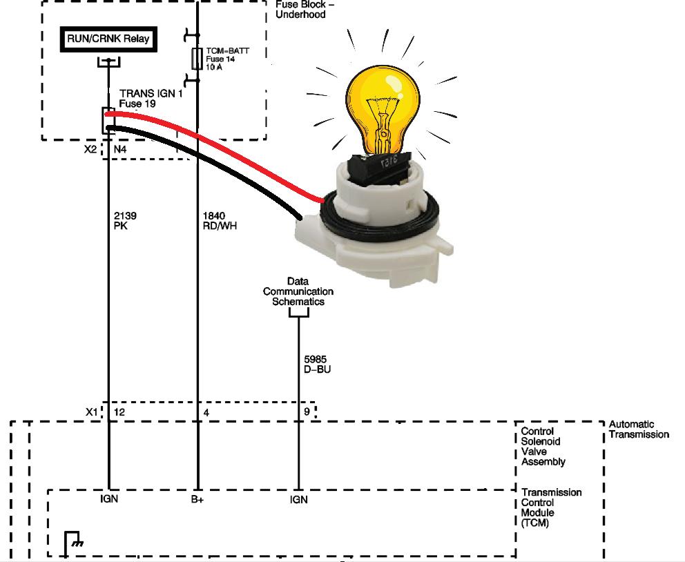
LEVERAGING EASY-TO-PERFORM tests that “infer” a particular issue exists should be accomplished well within the first diagnostic hour. Use these test results to justify additional required diagnostic time.
PHOTO COURTESY BRANDON STECKLER

NEEDLESS TO say, earning more money is desirable for anyone. However, spending more money is a different story. If customers can see a value in the cost (and it’s within their budget), seeking more diagnostic time is easier. However, customer-facing team members need to feel confident in this diagnostic charge in order to sell it effectively. This can’t occur unless adequate communication occurs for all parties involved (customer, advisor, and technician).
PHOTO COURTESY BRANDON STECKLER




We then discussed potential approaches to easily determine which fault existed. A reminder: a solenoid isn’t typically energized under all operating conditions. If a solenoid were the source of the short circuit, the fuse should blow only when that solenoid is energized. If the fuse opened under any operating condition, the fault was either harness-related or the TCM itself.
Analysis began by first substituting the
fuse for a device that accomplishes two goals for us as diagnosticians. It must first offer circuit protection so we can continue troubleshooting without causing further damage to the associated circuitry. It must also indicate whether or not the fault is present. A simple incandescent light bulb would do the trick.
If no fault was present, the bulb might not energize/illuminate at all. Or the bulb may energize but not illuminate brilliantly. In that scenario, the bulb would behave as just described because
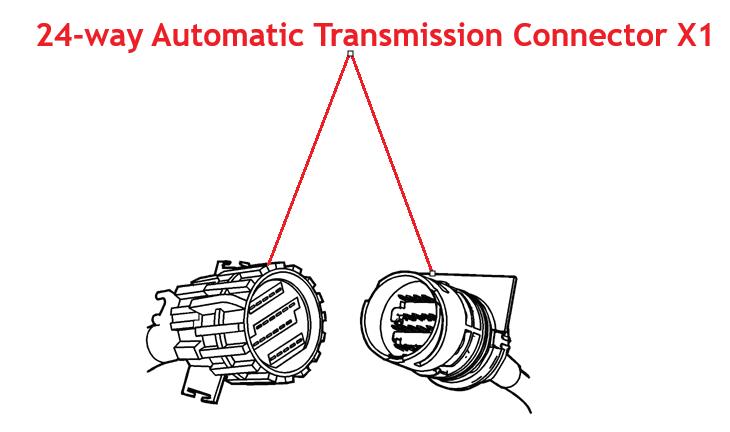
CIRCUIT ISOLATION is a quick and easy way further to support a theory on a fault’s location. Ideally, this should be easy to do. As shown here, decoupling this connector implements this technique, as it’s easily accessible (external to the transmission assembly).
PHOTO COURTESY BRANDON STECKLER
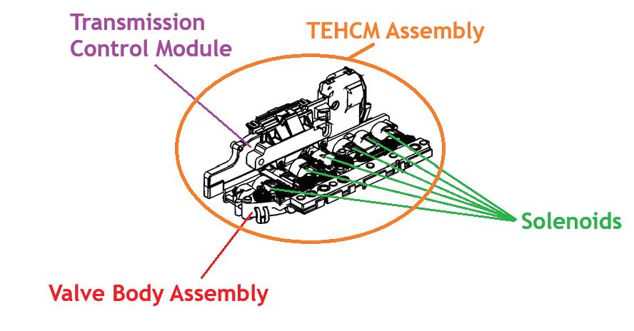
COMMON configuration among today’s automatic transmissions: the transmission control module is integral to the hydraulic controls and can’t be accessed without entering the transmission’s fluid pan.
a path to ground would be present (but through the intended loads, not a direct short to ground).
The bulb was connected to the circuit in place of the blown fuse. As a result, the lamp illuminated brilliantly, indicating the short to ground was present. This occurred when the ignition key was “on.” This great preliminary information led us to the next logical step: component isolation.
In this vehicle’s topology, the harness is most easily isolated from the transmission assembly directly at the transmission’s 24way main connector, X1. After disconnecting the harness from the transmission, the bulb ceased to illuminate.
Although the results of the above test isolated the short to within the transmission itself, we didn’t know if the fault was within a solenoid or the TEHCM assembly. Either way, internal components would have to be accessed, meaning disassembly is required to pursue a pinpointed diagnosis further.
Frequently, technicians seeking more diagnostic time are viewed as “sour grapes” or greedy. Although many times the tech is undertooled for the diagnosis, lacks the proper service information, and/or the understanding necessary to pursue the fault, and that’s the reason they seek more time (as padding).
However, in many cases, this occurs because the tech doesn’t typically share the reason for requesting additional time. Again, this all goes back to a lack of communication and documentation.
Consider a system that keeps technicians on the “straight and narrow” for the first diagnostic hour. A system that discourages a technician from disassembly and instead leverages easy-to-perform, surface-level testing that justifies requesting additional diagnostic time. In situations like this, the diagnostic levels could be defined ahead of time and explained to the customer in detail.







I look at it like this: if the customer chose to end the pursuit after a second diagnostic hour was requested, the value for the first diagnostic hour should already have been realized. In this case, the first diagnostic hour should correlate to the promises already made to the customer, and would have paid for:
• Visual preliminary inspection and/or road testing
• Full vehicle DTC scan
• Inspection and discovery of open fuse
At this point, even though the vehicle evaluation thus far took only a few minutes, the knowledge gained from the technician’s tenure and experience brought value to what was discovered and how it was discovered. In other words, more diagnostic time to pursue the proven circuit fault is justified. It isn’t ideal or prudent to spend the time to access the TEHCM for internal circuit testing/isolation at this point—within the first diagnostic hour. However, without proper communication with the rest of the team, as the tech requests more diagnostic time, the advisor’s perspective (as well as the customer’s) shows the tech has another 45 minutes to invest prior to seeking more.
A Potential Solution
Want to avoid situations like this one? Try this demonstration of communication on for size:
Level-1 diagnosis = 1 hour (15 minutes invested)
• Customer states “transmission performance degraded.”
• Vehicle cannot be operated safely on motorway.
• Scan for DTCs… “P0XXX” and “UXXXX” stored, unable to establish communication with Transmission Control Module.
• Inspected and found blown fuse No. 19 (15A) in under-hood fuse block.
• Fuse replaced; opens upon subsequent key-on event.
• Must pursue root cause of circuit No. 1850 (pink wire) overload prior to further transmission performance evaluation.
• REQUEST ADDITIONAL DIAGNOSTIC TIME FOR CIRCUIT/COMPONENT ISOLATION. CUSTOMER APPROVED ADDITIONAL DIAGNOSTIC HOUR
Level-2 diagnosis = 1 hour (5 more minutes invested)
• Fuse No. 19 substituted with circuit protection; short circuit is present.
• Isolated transmission assembly from wire harness; short circuit eliminated.
• Fault found to be internal to transmission assembly.
• Considering high mileage (200,000-plus miles) and inability to evaluate transmission conditions otherwise, suggestion is to replace transmission assembly and program/configure TEHCM.
Although the circumstances are unfavorable, the technician is demonstrating his concern for the customer’s best interest. He’s also demonstrated his professionalism in that he has built in the value for both diagnostic hours charged to the customer.
cost of the component and software programming (with the potential to find out only later that the transmission has internal mechanical faults).
The other scenario is to have sold the customer a transmission assembly (without proper diagnosis), only to find out the wire harness was simply shorted externally. The symptom would still have remained, and the customer would have invested potentially thousands of dollars unnecessarily.
We could come up with several scenarios, but there aren’t many honest scenarios where everyone wins. Communication between the customer and service advisor, as well as the service advisor and technician (and back again), is crucial to maintain the level of professionalism that ensures customers keep coming back.
Technicians need to be paid fairly to do the job correctly. Advisors can’t sell with confidence if technicians ask for more time arbitrarily. And customers won’t want to spend their hard-earned money if there is little perceived value.
What’s the solution? It’s simple: we all need to try a bit harder to work as a team. Start tomorrow and see how fast the numbers will reflect the teamwork. I can promise you that.

This win/win/win situation allows the service advisor to sell additional diagnostic time (with confidence) to the customer, the technician to be paid properly for the justified diagnostic time required (with productivity topping 600%), and most importantly, the customer to realize the perceived value of diagnostic charges required.
The end result: the customer avoided spending money on replacement of a TEHCM for three hours of R/R, plus the
BRANDON STECKLER is an ASE Master Technician (A1-A9, C1, and advanced level designations in L1, L2, L3, L4, and xEV-Level 2) and a certified instructor with expertise in automotive diagnostics and driveability. He earned GM Automotive Service Education credentials from Northampton County Community College. With more than 20 years of experience spanning dealerships and independent shops, he instructs at Carquest Technical Institute and Worldpac Training Institute, authors books and classes, and provides technical support through Steckler Automotive Technical Services.



















From vacuum-operated valves to VVT-driven internal flow, today’s exhaust gas recirculation touches nearly every aspect of engine operation—and reshapes how technicians diagnose it BY ERIK SCREEDEN























































WE KNOW THAT THE INTERNAL COMBUSTION ENGINE produces many harmful emissions. Hydrocarbons (HC), which are unburned fuel, and carbon monoxide (CO), directly and indirectly act as greenhouse gases and reduce oxygen availability. NOx (NO and NO₂) poses significant human health hazards and is a major factor in photochemical smog and acid rain. The modern three-way catalytic converter (TWC) uses a ceramic substrate coated in a wash coat of platinum (Pt), palladium (Pd), and rhodium (Rh) to help convert these gases from the harmful elements listed above to less harmful elements like N₂, CO₂, and H₂O. But the TWC needs a helping hand. It relies on the engine control module (ECM) to control the air/fuel ratio to keep it as close as possible to the stoichiometric 14.7:1 ratio for optimized catalyst efficiency. The TWC also relies on the ECM to help lower combustion temperatures to keep the amount of NOx leaving the combustion chamber at more manageable levels.
So, what is NOx? Nitrogen oxides are formed when oxygen and nitrogen combine in high-temperature combustion. Our atmosphere, which is made up of approximately 78% nitrogen and 21% oxygen, contains both these elements in abundant amounts. NOx occurs naturally in our atmosphere, and scientists agree that naturally occurring NOx emissions account for roughly onethird of total global NOx emissions. The other two-thirds are man-made. But just because something is naturally occurring doesn’t mean it isn’t harmful, and scientists began to realize in the mid-20th century that there are things we can do to mitigate some of these harmful pollutants.
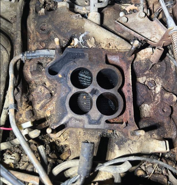
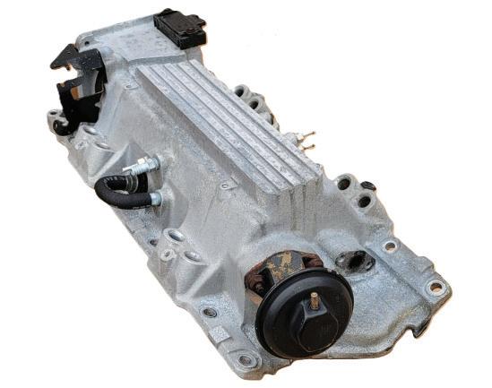
The first exhaust gas recirculation (EGR) systems came on the scene in the early 1970s. The early EGR systems were very simple. A vacuum-operated valve
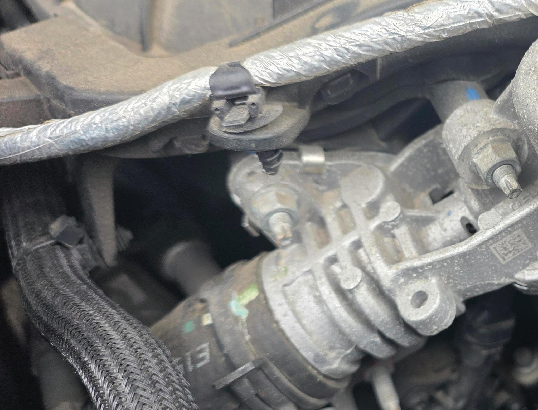
PHOTO BY ERIK SCREEDEN
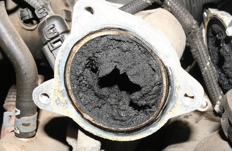
would open under light load conditions, allowing exhaust gas from the exhaust manifold to enter the intake manifold. The system relied on basic inputs, such as ported vacuum and thermal switches, and diagnostics were largely mechanical. Common failures included carbon clogging in EGR passages, ruptured vacuum diaphragms, and sticking pintle valves. These were straightforward systems with failures that were generally accompanied by obvious symptoms— rough idle, stalling, and poor acceleration. As EGR technology evolved into the 1990s and the industry transitioned into OBD II, we started to see the addition of EGR position sensors, differential pressure feedback (DPFE) sensors, and ECM-controlled EGR solenoids. These additions allowed the ECM to monitor EGR flow more directly and allowed for the setting of diagnostic trouble codes when EGR performance fell outside of expected ranges.
In today’s gasoline engines, EGR is part of a coordinated airflow and combustion strategy managed by the ECM. That strategy includes electronic EGR valve control, integration with electronic throttle control, interaction with variable valve timing (VVT), and airflow modeling using a multitude of sensor inputs. The system aims to introduce exhaust gases precisely based on real-time engine conditions. Today, it’s not only about reducing harmful NOx emissions; through reduced throttle loss and reduced heat rejection, EGR can actually increase efficiency. Throttle loss is simply the energy lost because of the restriction of the throttle plate. By nature, a closed throttle is a restriction, and the engine needs to work harder to draw in air. By filling the cylinder with inert exhaust gas, the throttle blade can be opened further
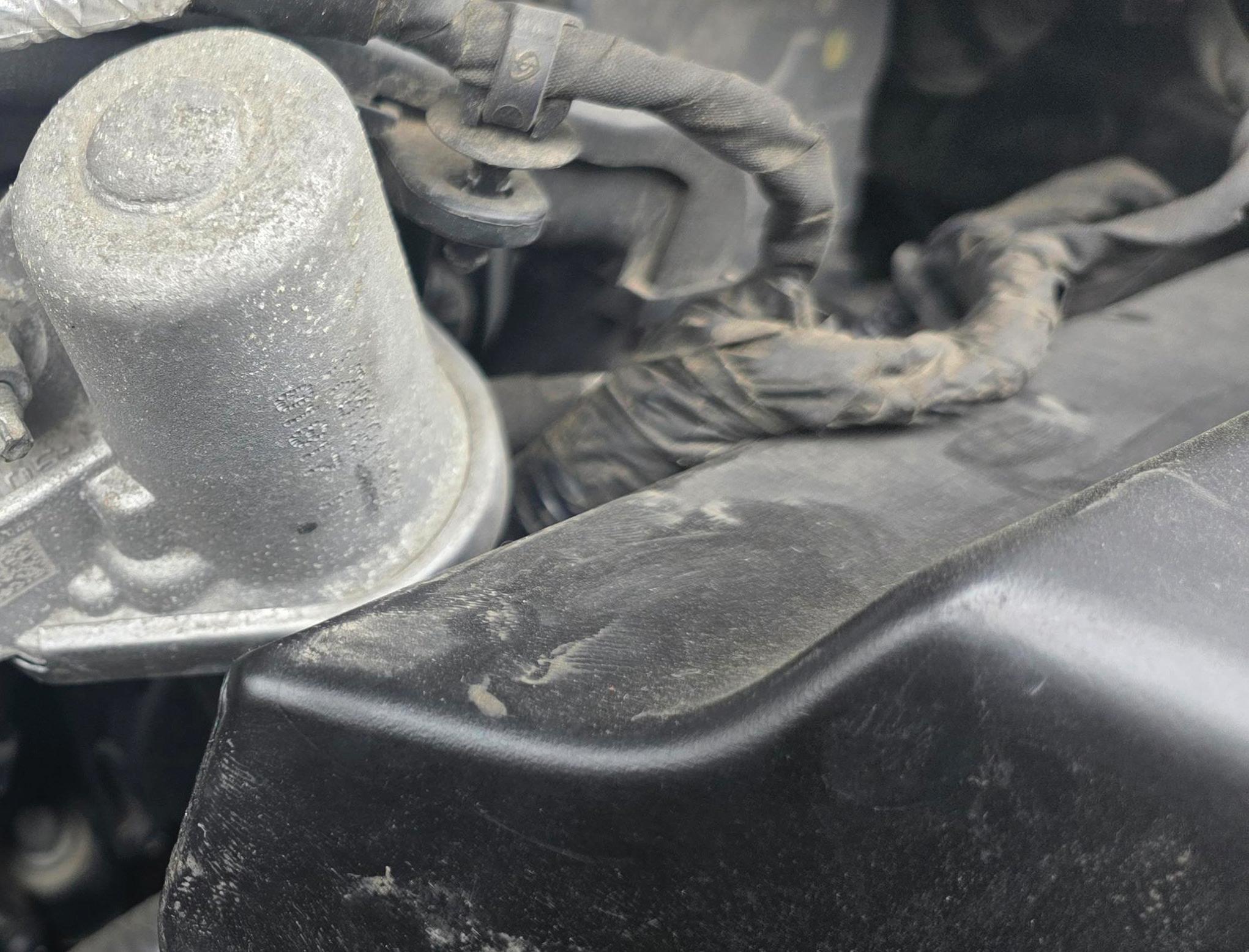
for a given power output, reducing that throttling loss. Reduced heat rejection increases efficiency because lower combustion temperatures also reduce the loss of thermal energy to combustion chamber surfaces, leaving more of that thermal energy for conversion to mechanical work during the power stroke.
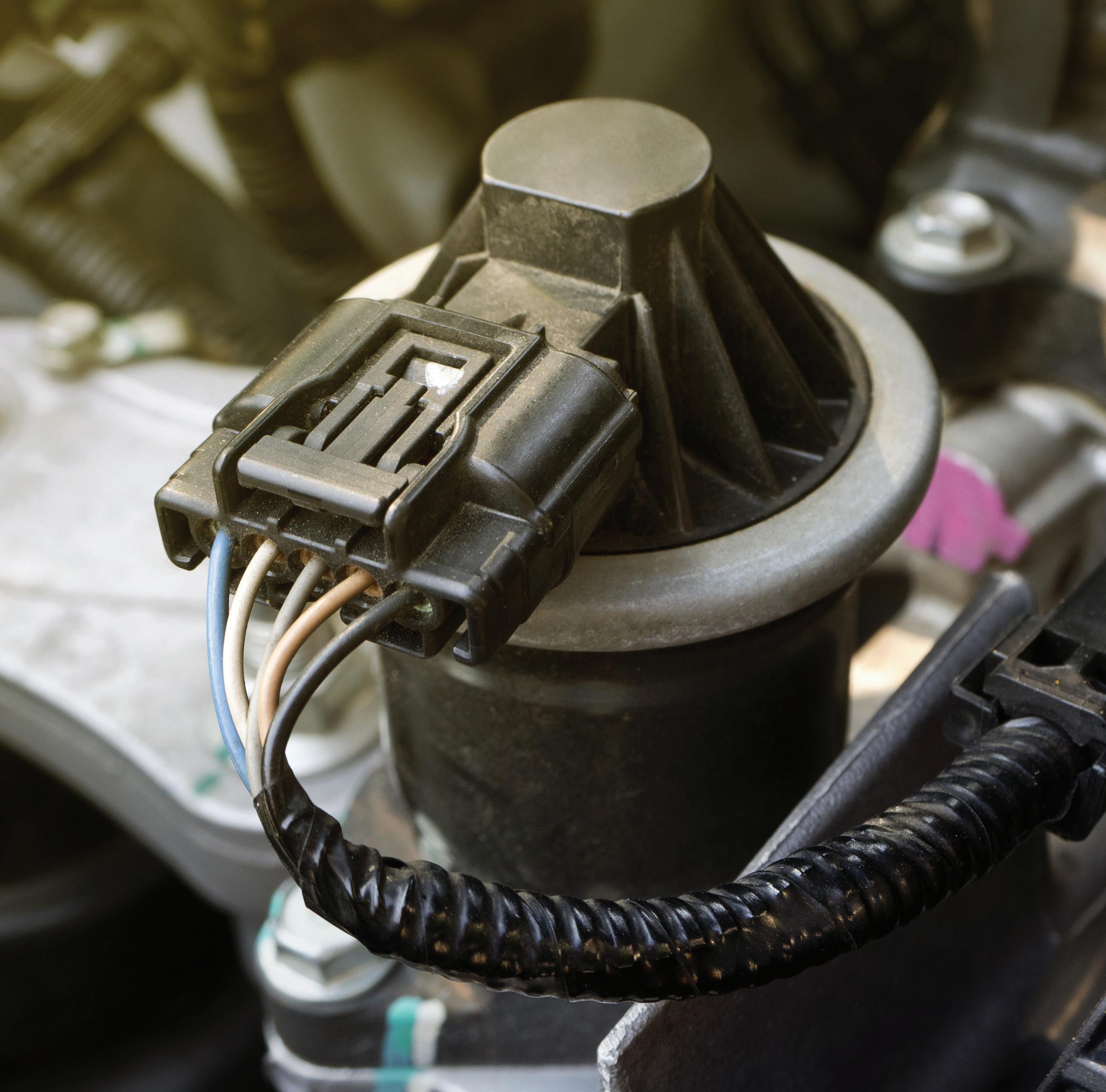
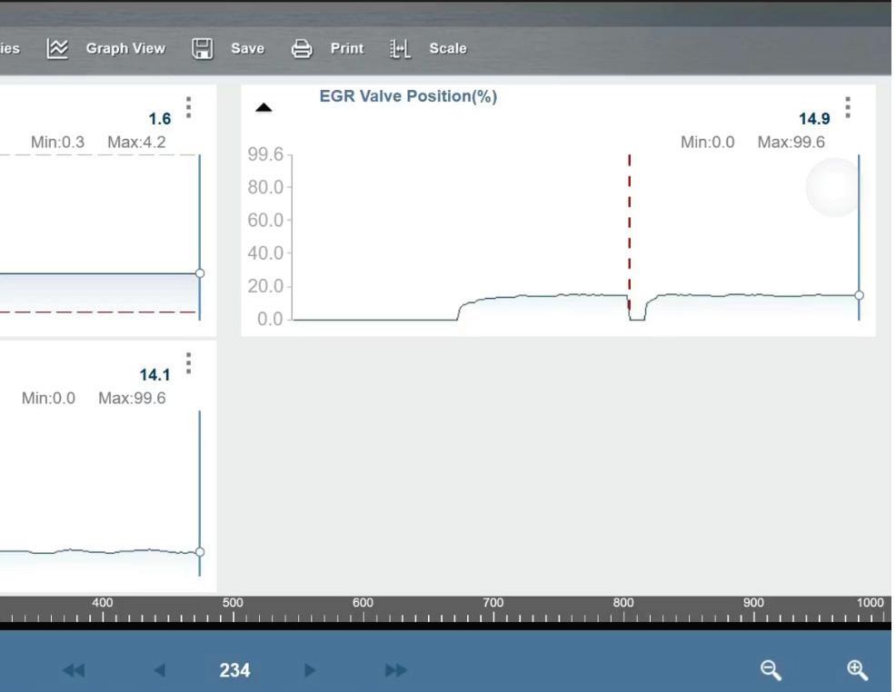
Today, EGR valves are electronically controlled (EEGR) and include position feedback. They no longer rely solely on vacuum; the ECM typically commands the valve directly using duty cycle or stepper motor control. The valve reports its position back to the ECM, allowing for closed-loop control. The ECM will know what it has commanded, and the ECM will know what the valve did. But the ECM needs to determine



if the correct amount of exhaust gas actually flowed back into the intake, because most of the time, EGR flow isn’t directly measured by the vehicle.
When the EGR valve is commanded open, exhaust gas is going to enter the intake stream, which displaces some of the incoming fresh air. The result is a measurable change in engine operating conditions. Many modern electronic EGR systems use feedback from the manifold absolute pressure (MAP) sensor to monitor EGR flow into the system. Intake manifold pressure is higher when EGR is flowing than when it isn’t. Therefore, when exhaust gas is circulated into the intake manifold, MAP sensor readings increase. The detection of EGR flow occurs by monitoring this increase in pressure. If the difference in pressure between EGR command on and off is below a minimum threshold, then a concern with the EGR valve has occurred.
EGR, OBD Readiness, and a Diagnostic Approach
EGR plays a direct role in OBD readiness monitors and emissions testing—particularly the EGR monitor itself. Drive cycles and strategy vary by manufacturer, but in general, to complete the monitor, the ECM must:
• Command EGR operation when conditions are met.
• Observe the expected change in airflow or combustion response.
• Verify that the system reacted, and did so within calibrated limits.
If those markers aren’t hit, the monitor won’t complete. While the EGR monitor with most manufacturers is fairly straightforward to reset, some manufacturers, such as Toyota, can be finicky and require involved drive cycles to get the I/M monitors to reset.







































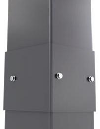




































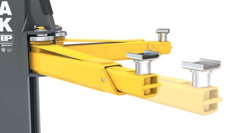



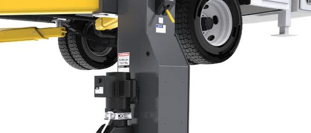









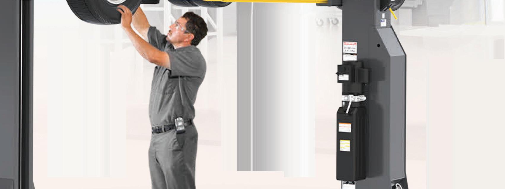
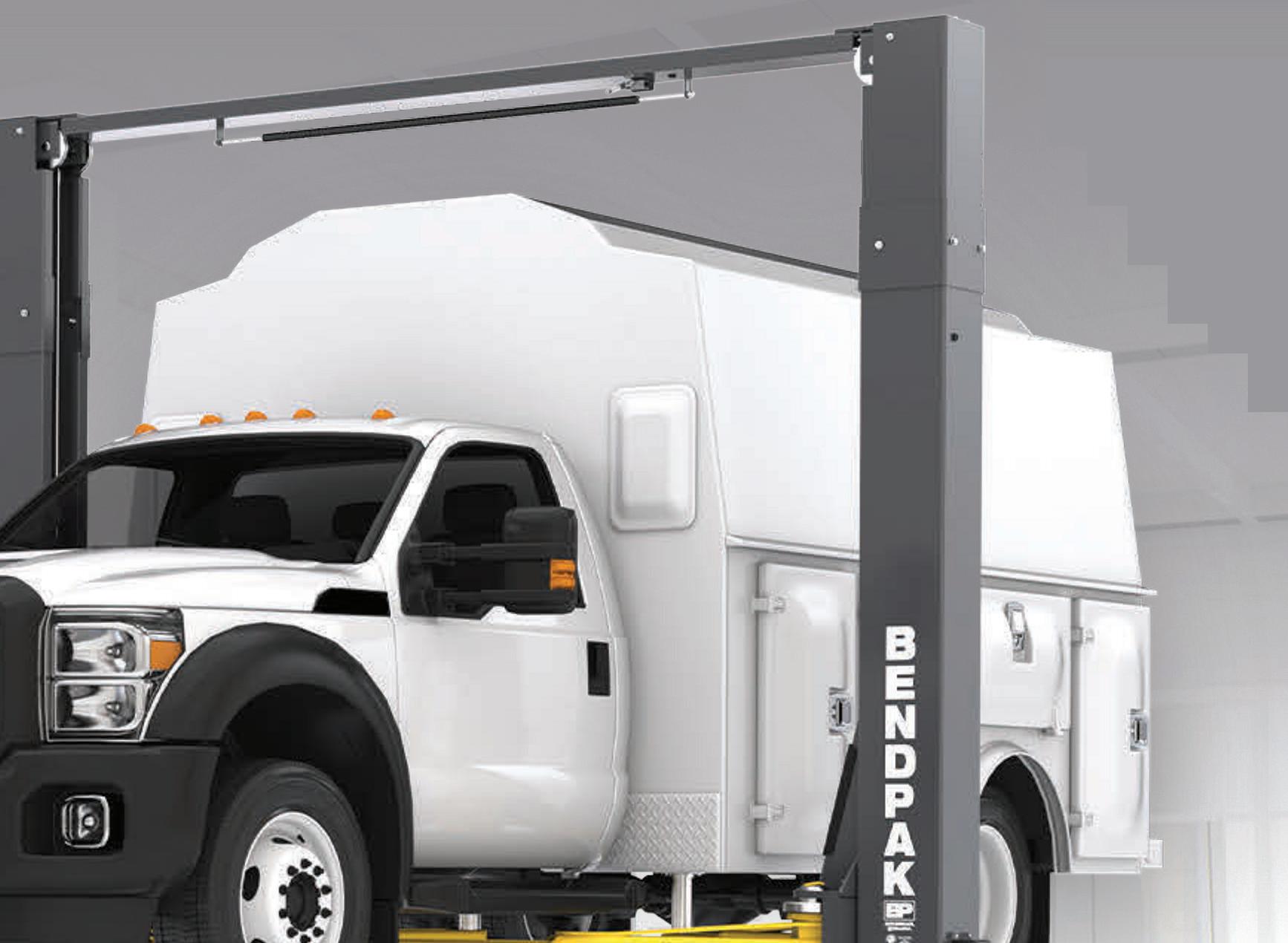
























































versatile choice for mixed fleets, BendPak’s new 16AP and 20AP Series heavy-duty two-post lifts easily take on Class 1 through 5 vehicles, from passenger cars to commercial trucks and vans. They reach further, lift higher and deliver greater stability than other lifts, all while protecting technicians with unmatched safety systems and ergonomics. With fewer moving parts, they’re easier to maintain, less prone to wear, and more cost-effective to operate. Maximize your uptime and efficiency with BendPak’s heavy-duty lifts — delivering superior performance and unmatched value. To learn more or to shop now, visit bendpak.com or call us at 1-800-253-2363







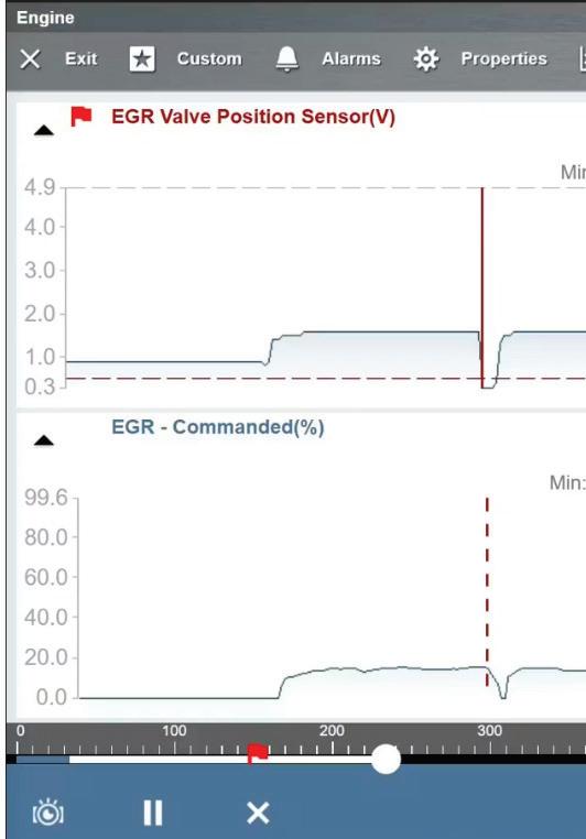
To effectively diagnose modern EGR systems, the technician is best to think past code-based diagnostics and focus more on system behavior. Start by confirming not only circuit integrity and that the valve is responding, but that the ECM is commanding EGR under the right conditions. Remember the old saying “garbage in, garbage out.” By reviewing system inputs in service information and then viewing live data—ideally in the conditions where EGR will be commanded—the technician can quickly gain a clear picture of whether the system has based its strategy on accurate information. Next, by understanding how the system monitors flow for that vehicle, the tech can verify things like: When EGR is introduced, how does MAP react? How does the MAF respond? Use bidirectional controls to observe these PIDs, and use your senses to verify that commanding the EGR open at idle produces a rough idle, a stumble, or even a stall. If there’s little change with a fully commanded EGR at idle, the system is probably not flowing as expected.
eXtra is a FREE, easy-to-use loyalty program for shop owners. Kind of like airline miles, but for the parts you’re already buying. You buy the parts, you earn rewards!




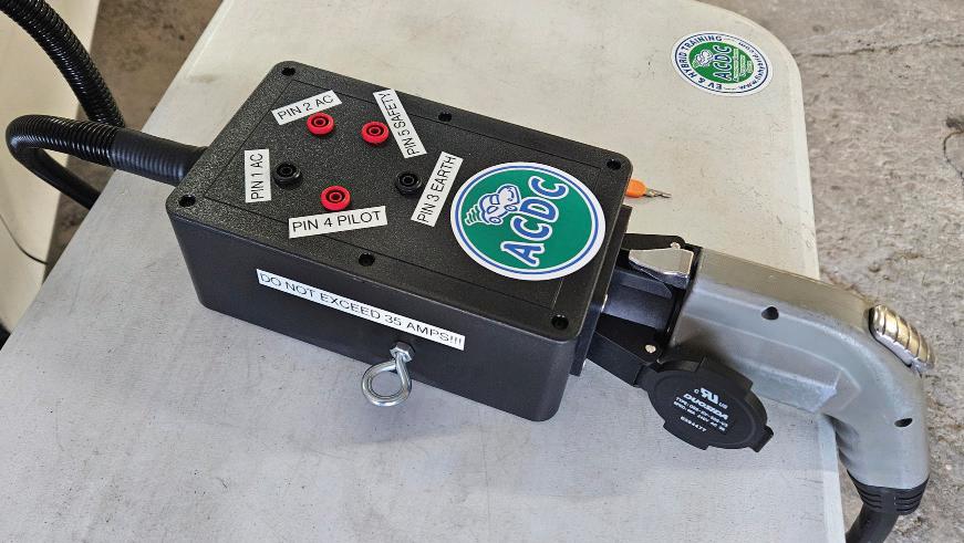
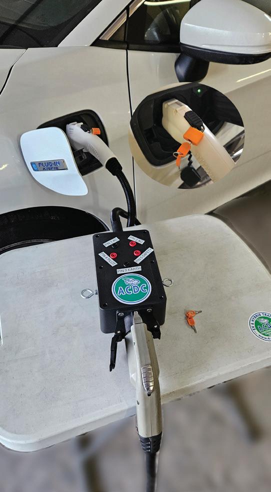
• Can you easily scope the J1772 connector?
• Is the problem the car or the EVSE?
• We have a break-out box designed by ACDC
• Complete with safety lockout, and a manual
• Works on Tesla’s with an adapter
OFFICE: 508-826-4546
EMAIL: CRAIG@FIXHYBRID.COM
WEB: WWW.FIXHYBRID.COM
Remember, because EGR monitoring is model-based, anything affecting airflow can influence diagnostics—things like dirty or biased MAF sensors, intake restrictions, vacuum leaks, and exhaust restrictions. A skewed input can lead to a skewed conclusion. Garbage in, garbage out.
EGR Leaves the Chat … Kind Of Variable valve timing has added another layer to EGR strategy. By adjusting valve overlap, engines can retain a portion of exhaust gases in the cylinder, creating an internal EGR effect. Common engine families, such as later-generation GM LS/LT variants, were able to do away with EGR valves altogether. You’ve probably noticed the shift in the OBD II non-continuous monitors from simply “EGR” listed to “EGR and/or VVT” listed; that’s exactly why.
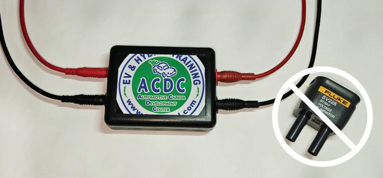
• Ghost Voltage will give you misleading DVOM readings on High Voltage systems
• How do you eliminate them?
$99 50 Plus S/H
• ACDC has engineered a solution, after Fluke stopped production of the SV225
“Internal EGR,” or using VVT to control NOx emissions in modern engines, allows for faster, more precise, and more efficient control over internal gas retention. Traditional EGR uses external valving and plumbing that can clog and react slowly. VVT manages NOx by optimizing valve overlap to retain exhaust gas.
Even without VVT, some manufacturers circumvented the need for an external EGR system. Starting halfway through the 2004 model year, the 5.9-liter Cummins found in the 2500 and 3500 series Dodge trucks underwent a “refresh” to meet stricter emissions standards. The 2004.5 trucks had several changes, but most notable for this story were the
change in cam profile, the addition of a catalytic converter, and injector event timing changes that allowed the truck to be 50-state legal without the use of an external EGR valve on the pickups (many medium-duty trucks retained a traditional external valve). Though the sum of the changes increased the power output of these engines north of 600 lb.-ft. of torque, many owners complained of fuel mileage reduction, a loss of idle quality, and significantly dirtier engine oil.
Low-pressure EGR has become an increasingly popular addition to NOx
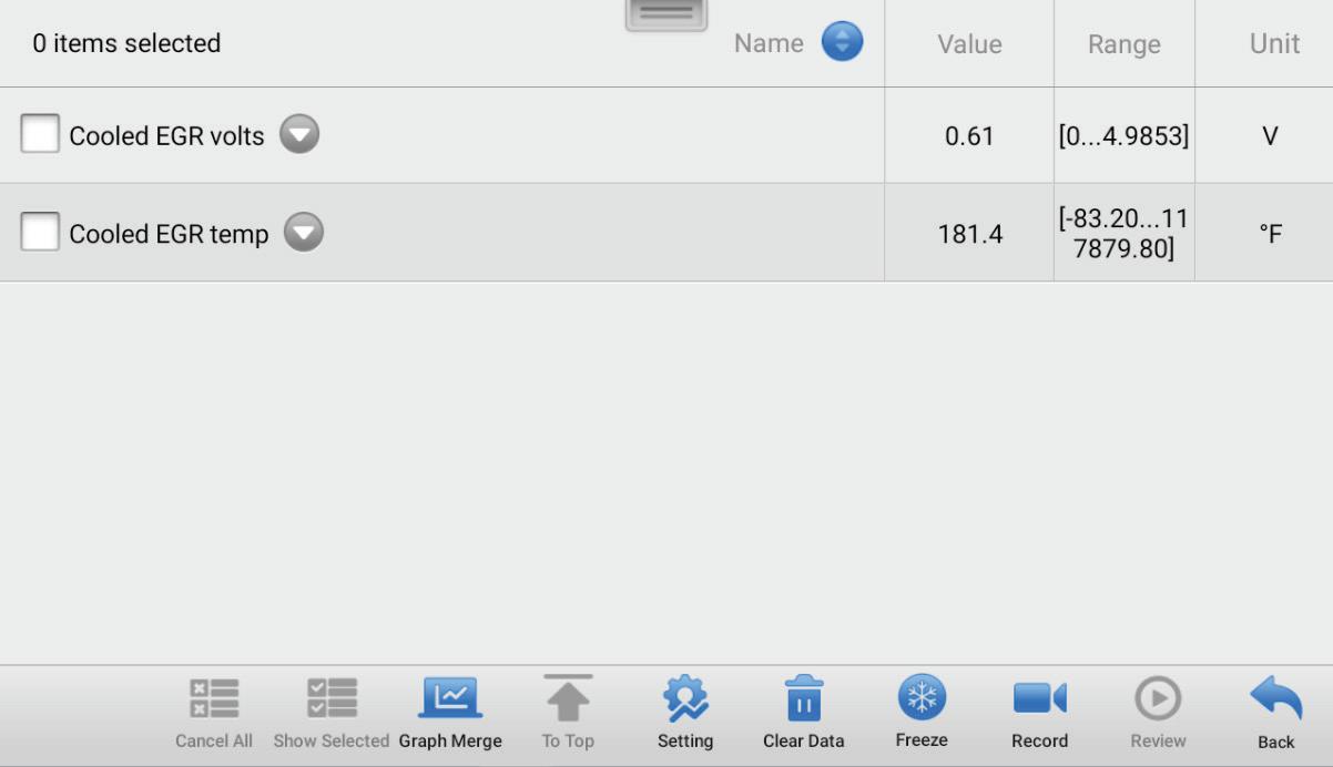
PHOTO BY NOAH NELSON
mitigation strategy for some vehicle manufacturers. While traditional “high-pressure” systems pull exhaust gas directly from, or relatively close to, the exhaust manifold to recirculate back into the intake stream, low-pressure systems—which are becoming popular, especially with diesel applications—draw exhaust gas after the aftertreatment system, downstream of the diesel particulate filter, and route it back into the intake.
This approach offers several advantages: cleaner exhaust gas with less soot, improved durability of EGR components, better control under high-load conditions, and enhanced compatibility with turbocharging. But low-pressure EGR isn’t without its challenges. The nature of what it is introduces complexity. You have longer routing paths, additional valves and coolers, and lower pressure differentials. All of this makes them more sensitive to restrictions, leaks, and cooler efficiency issues. And these, too, rely on modeled airflow rather than direct measurement.
EGR has been a hot topic with diesel owners for a couple of decades now. In the early 2000s, truck manufacturers were tasked with hitting more stringent emissions standards. While some NOx mitigation strategies—such as the addition of intercoolers to turbocharged applications—were popular because of
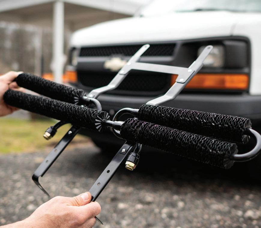
Whether you’re looking for a direct replacement for a corroded or damaged cooler, or an upgraded repair solution not offered by the OEM, Dorman has the product you need.

their performance enhancements, others, like EGR and EGR coolers, weren’t.
Exhaust gas entering a combustion chamber has a couple of effects: it reduces available O₂ in the cylinder, and it reduces combustion temperature. That reduced combustion temperature leads to a lower combustion rate and higher heat capacity. Simply put, EGR makes the diesel burn slower. A diesel combustion event almost always has significantly more oxygen than it needs for combustion, so when the diesel molecules are introduced into the combustion chamber, all that oxygen ensures that combustion happens quickly, and that intense combustion event leads to very high combustion temperatures. So if you introduce inert exhaust gas into the cylinder, you reduce the available oxygen. If you reduce the available oxygen, you reduce the combustion temperature because the diesel burns more slowly, and if you do that, you reduce the creation of NOx emissions. Where some of the unpopularity comes in: lower combustion temperatures also equate to lower power output and lower efficiency.
There are also other arguments that some diesel owners will use to justify deleting EGR valving and coolers, such as that it increases soot production and reduces engine life. And while EGR on a diesel engine will absolutely increase soot production—and when you mix that soot with oily crankcase vapors, it can create an absolutely unholy buildup that can lower performance and damage variable-geometry turbochargers—EGR itself, through numerous studies, hasn’t been shown to significantly increase wear in diesel engines under normal driving conditions. While many parts of the country don’t actively enforce emissions regulations, tampering with emissions components can land shop owners, management, and technicians in
significant trouble. As a technician who worked in the performance industry, I encourage others to research their exposure to liability when performing modifications on behalf of their employer, so at least they’re informed of what their potential personal culpability could be before they go and break federal law.
EGR is no longer just a simple emissions add-on; it’s a fully integrated strategy that touches nearly every aspect of modern engine operation. From early vacuum-operated valves to today’s electronically controlled and even “internal” EGR through VVT or camshaft profile, the goal remains the same: control combustion temperatures and manage NOx while limiting effects on performance or efficiency as much as possible. For technicians, that evolution means diagnostics must evolve as well. Understanding how the ECM commands, models, and verifies EGR flow, along with how other systems influence it, is critical to making accurate, efficient repairs. Whether it’s a traditional valve, a cam-driven internal strategy, or a low-pressure setup, the goal remains the same. And while EGR may look different than it used to, its impact on engine performance, emissions, and diagnostics has never been greater.

ERIK SCREEDEN serves as technical and multimedia content director for Motor Age. An ASE Master Technician with L1 and L4 credentials, he brings more than 25 years of industry experience. Screeden began his career as a Ford dealership technician, later working at independent repair facilities and a GM-specific performance shop. He transitioned to diagnostic and J2534 tool support before finally leveraging his expertise in technical sales.
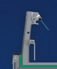




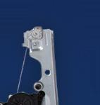

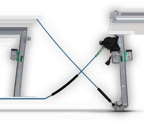
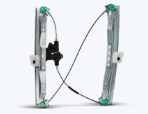
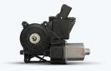
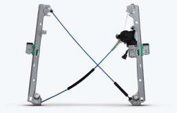
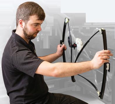
Motor and regulator are pre-aligned to deliver consistent, smooth window movement from the first use.
Engineered to OE-matching specs, our complete assembly installs easily without drilling or modification.
Each unit is tested as a complete system to ensure quiet, reliable operation under real-world conditions.




From rod chamfers and bearing tangs to asymmetric skirts and offset wrist pins, here’s what every engine assembler should verify before torquing the cap
BY MIKE MAVRIGIAN
DEPENDING ON THE ENGINE APPLICATION, it isn’t uncommon for an engine assembler to question the correct orientation of pistons to connecting rods. Ignoring this can result in problems.
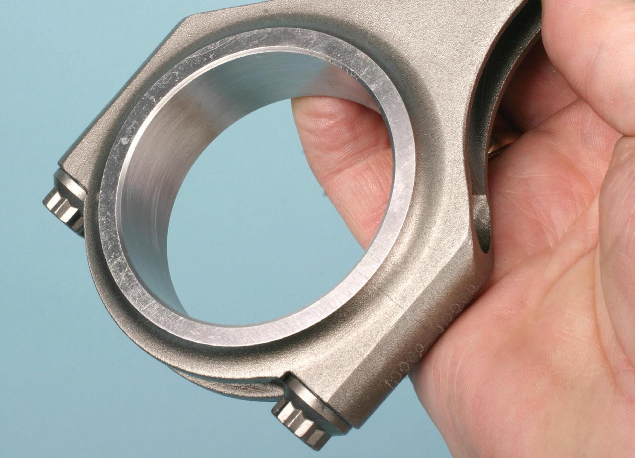
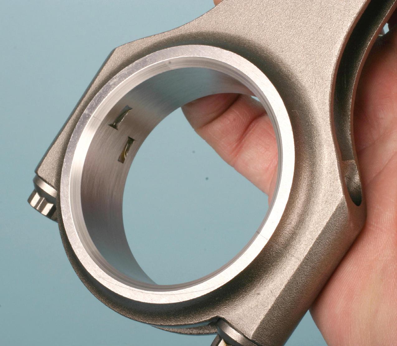
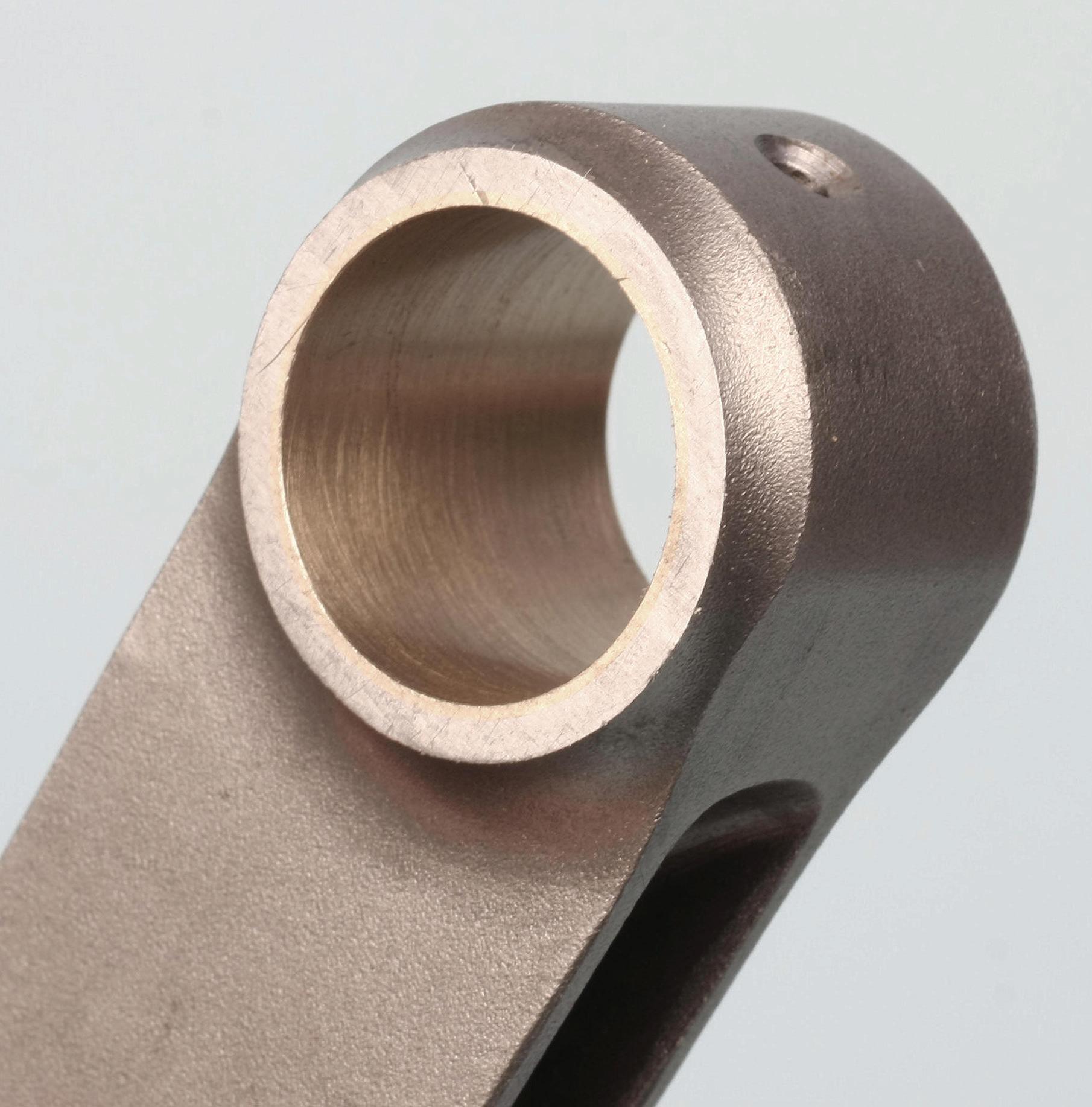
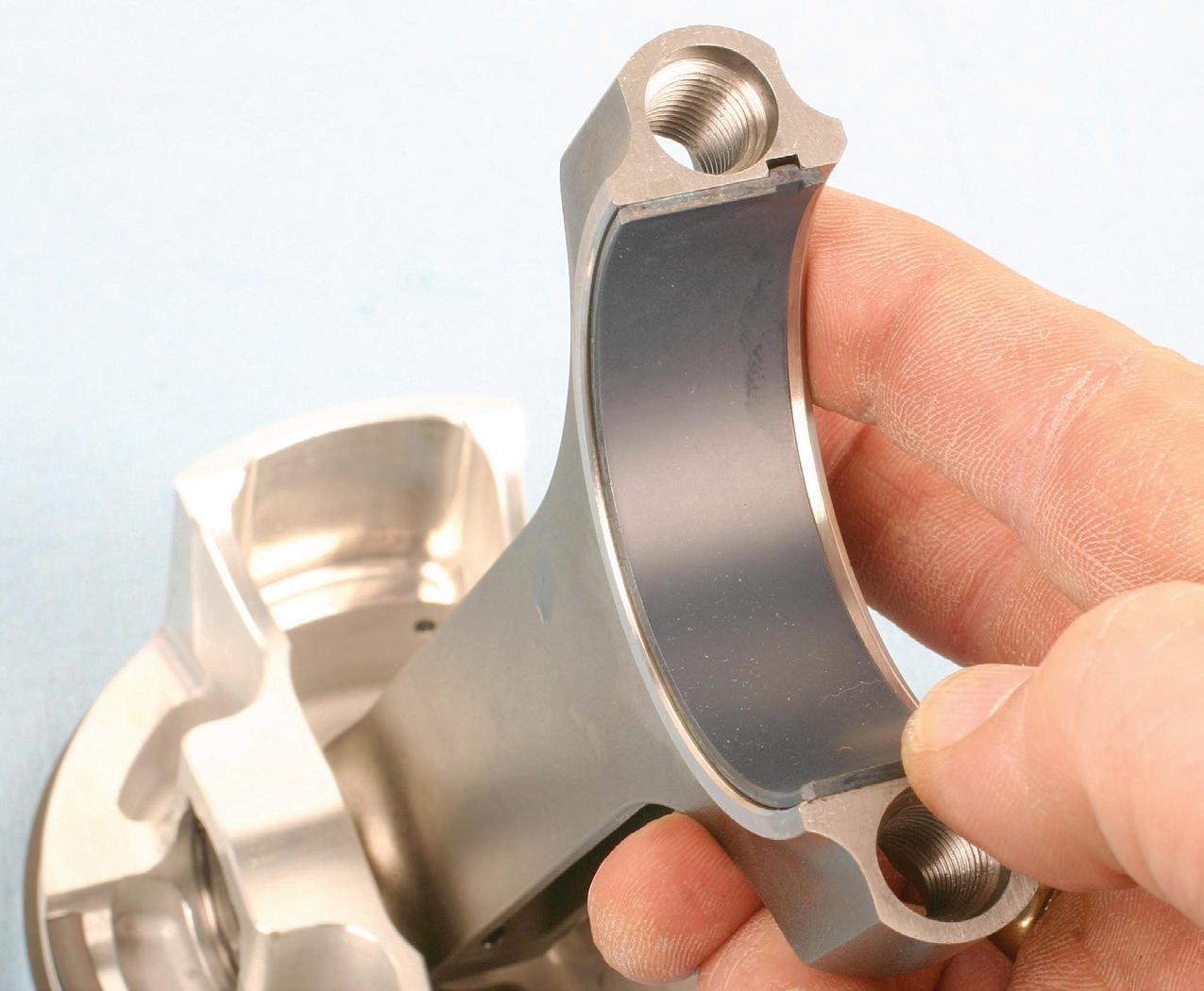
Let’s start with connecting rods relative to placement on the crankshaft. The rod’s big end may feature a slight chamfer on one side of the rod, with the opposite side featuring no chamfer at all. Always place the side that features a chamfer next to the crankshaft rod journal, which features a slight radius. This allows the chamfered side of the rod to clear the journal’s radius. If the rods are designed for use on a crank that doesn’t feature a radiused fillet, the rods might not feature a large chamfer on one side. In this case, orient the rod so that the rod bearing tang grooves face outward toward the oil pan rail or face inboard. In either case, orient all rods in the same manner. Some engine designs may specify this orientation.
The upper saddle of the rod’s big end and the rod cap feature short grooves at the parting line area. Contrary to popular belief, these grooves aren’t intended to prevent rod bearing “spin” or rotation. In reality, the grooves (and male protrusions on the back of the bearings) simply exist to provide ease of properly aligning and locating the bearings. The bearings are locked in place once the rod cap is fully tightened to the specified clamping load, creating the critical upper-to-lower rod bearing radial crush.
(Note: Some OEM engine designs may use rod bearings that don’t feature locating tangs, one example is the Chrysler 3.7L and 4.7L engine family. This is done merely to reduce manufacturing costs. When installing tangless rod bearings, it’s up to the assembler to pay attention to properly centering the rod bearings in their respective saddles.)
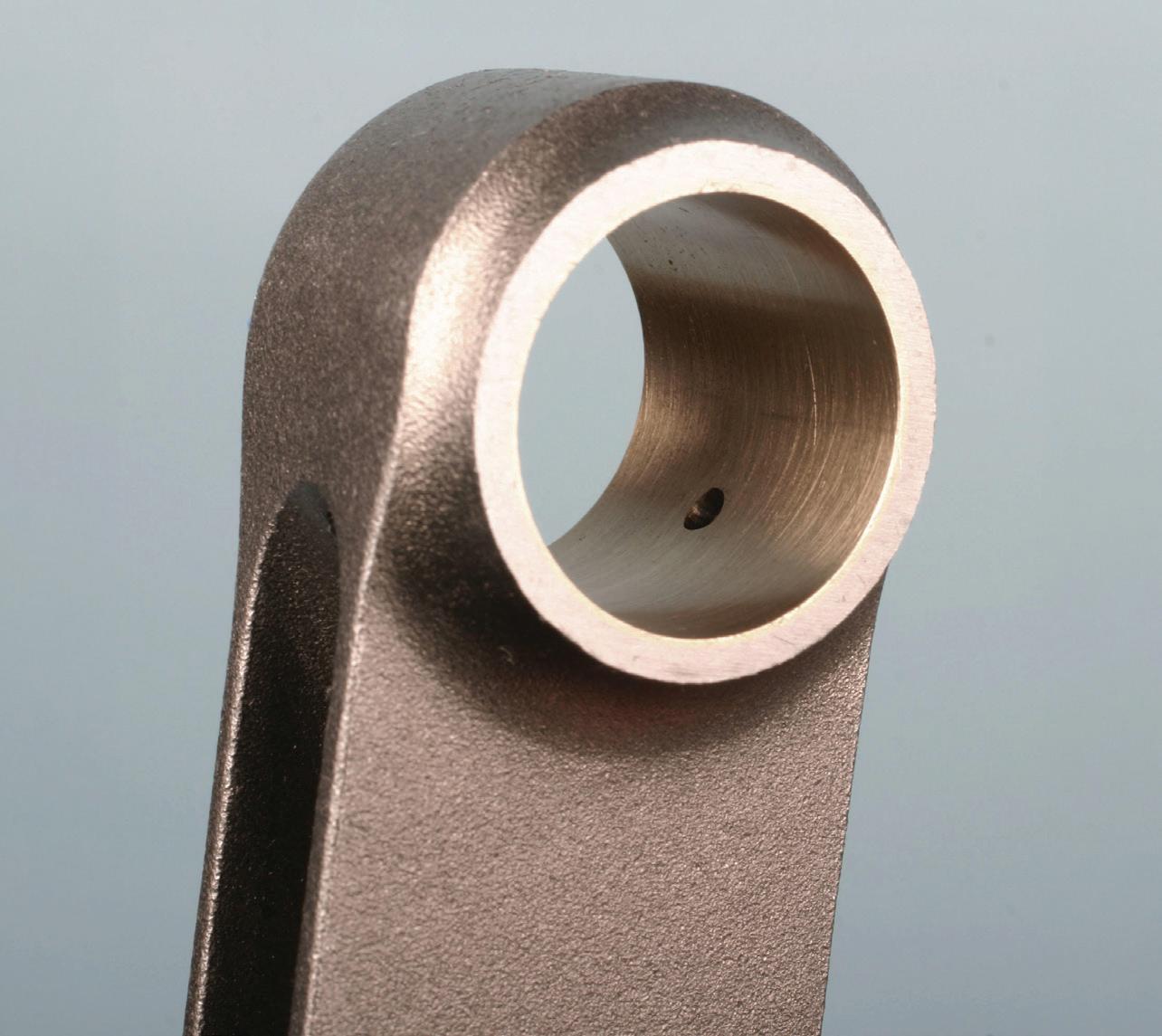
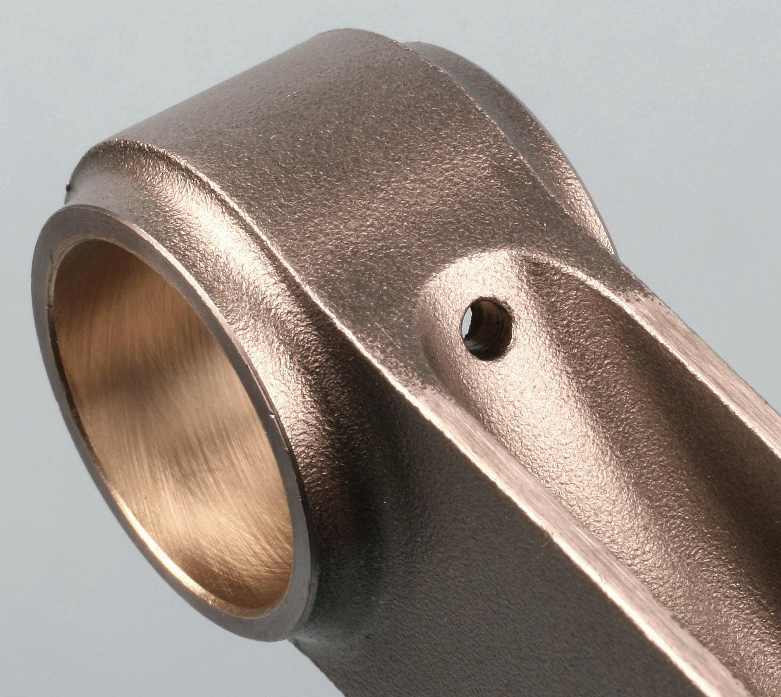
Be aware that some connecting rods may feature an offset design. This refers to either the large or small end being slightly offset relative to the centerline of the rod beam. This is done to accommodate engine designs where the centerline of the cylinder bore is slightly offset relative to the rod bearing radial centerline. This offset may be as much as 0.100” or so. During test fitting, it’s important to verify that the small end of the rod is centered on the wrist pin
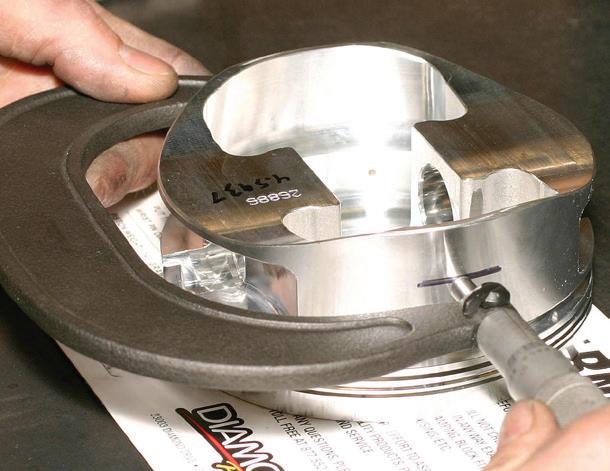
(there should be equal spacing between the rod’s small end and each of the piston’s pin bosses).
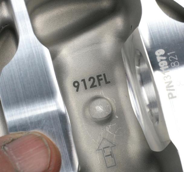
Some connecting rod big ends may feature a small oil “squirt” hole in one side of the rod’s big end. The purpose of this hole is to allow oil to be squirted toward opposing pistons. If the rod’s big end has an oil hole, the big end of the rod with the oil hole should be oriented to face toward the camshaft (in a single-cam V
engine). Some rod small ends may feature a small oil hole. This is intended to provide additional “splash” oil to the wrist pin.
It should be obvious, but when a piston features valve reliefs, the side of the piston that has these reliefs must align with the location of the intake and exhaust valves. For instance, on a V-platform engine, the reliefs are biased toward the intake manifold. If you’re in doubt, pay attention to the piston dome’s valve pockets.






by BendPak
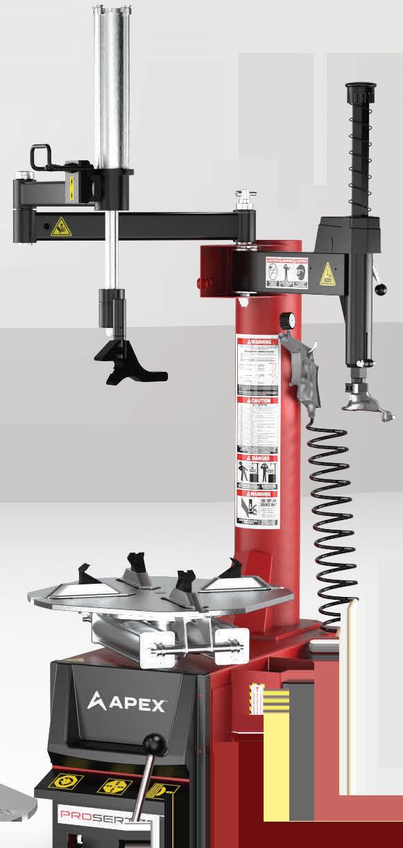
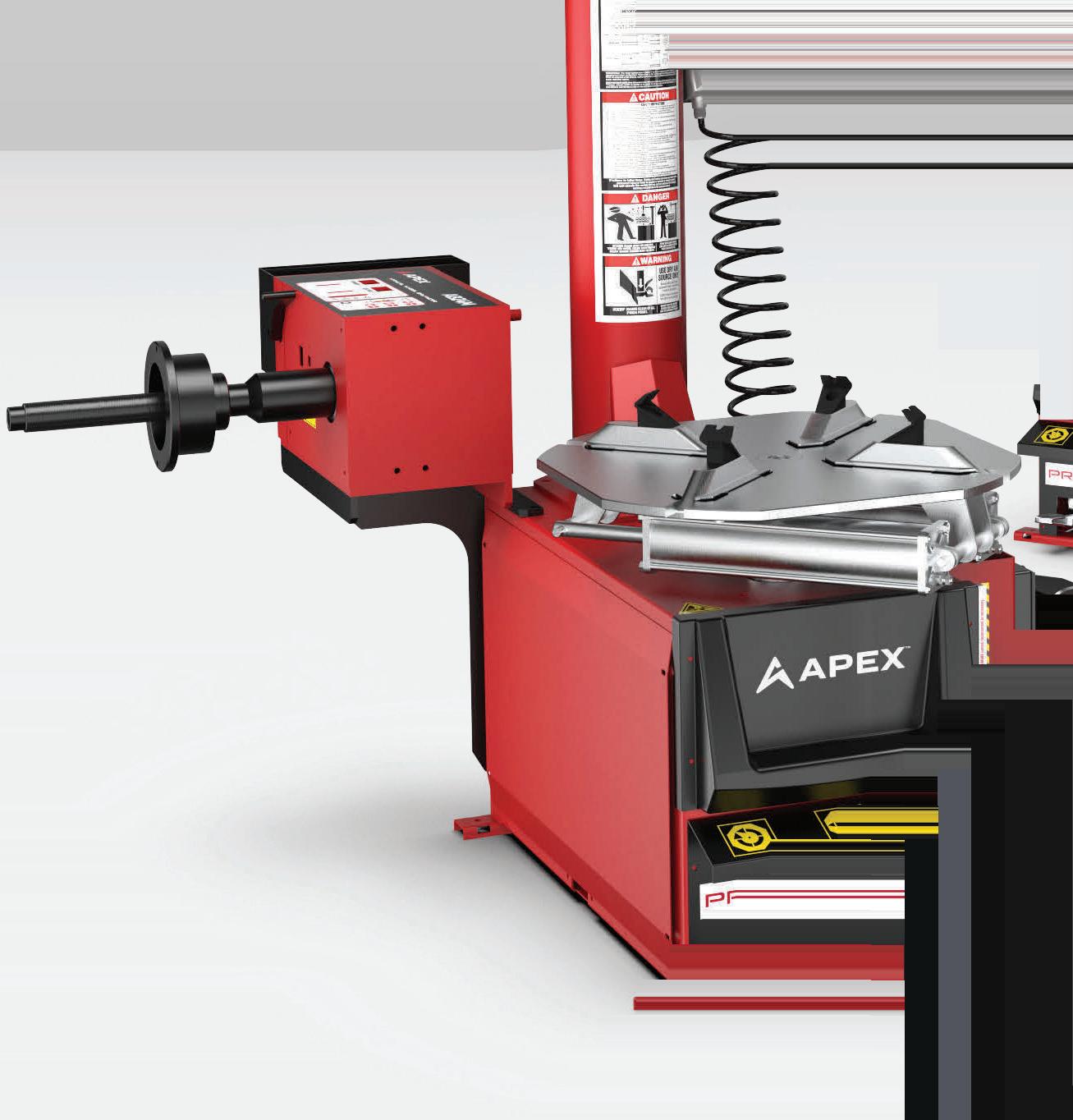
APEX by BendPak delivers dependable wheel service performance built for daily shop use, with tire changers that provide consistent clamping, smooth bead breaking, and controlled operation, paired with wheel balancers engineered for accurate, repeatable measurements and fast cycle times. Every APEX wheel service machine is designed for stability, precision, and durability, giving technicians reliable results vehicle after vehicle without unnecessary complexity or wasted features.















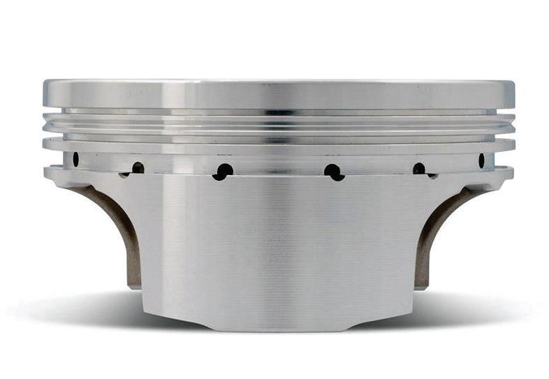
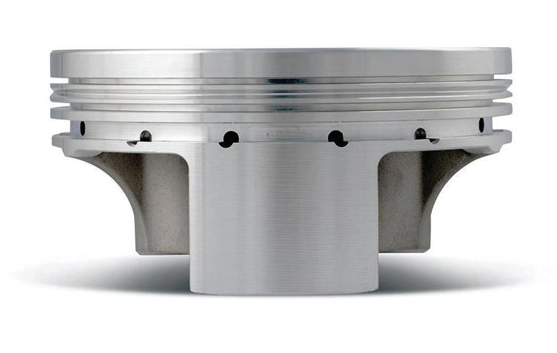
It may be surprising to some, but piston skirts aren’t perfectly round. Each inboard and outboard side of the piston experiences different levels of loading during operation. Actually, the piston skirt area is slightly “barrel” shaped to provide an adequate surface load against the cylinder wall while reducing friction. This surface area is responsible for providing piston stability to minimize rocking relative to the pin axis as the piston moves down from TDC and back up from BDC.
The major thrust face is the side of the piston that receives the thrust on the power stroke. As viewed facing the front of the engine, if the crankshaft is rotating clockwise, the major thrust face is on the left side of the cylinder. On the driver-side bank, major thrust is experienced on the intake side; on the passenger side, major thrust is on the exhaust side. The opposite side of the piston—the minor thrust side—experiences loading force on the compression stroke. The major thrust side is the side of the piston skirt that experiences the majority of thrust loading. To put this into perspective, during the firing cycle, the load experienced on the major thrust side skirt can be as much as 10 times greater than the load experienced on the minor thrust side skirt. The difference in skirt loading will vary depending on variables such as crankshaft stroke, connecting rod length, and peak cylinder pressures. When the piston is pushed down during the power stroke, it experiences resistance as it attempts to turn the crankshaft. As load increases, the amount of resistance increases. During this resistance, the piston side load is forced to one side—the major thrust side—which places more force (with subsequently increased friction and potential wear) on the thrust side of the cylinder wall. If the piston dome features a reference dot or other mark,








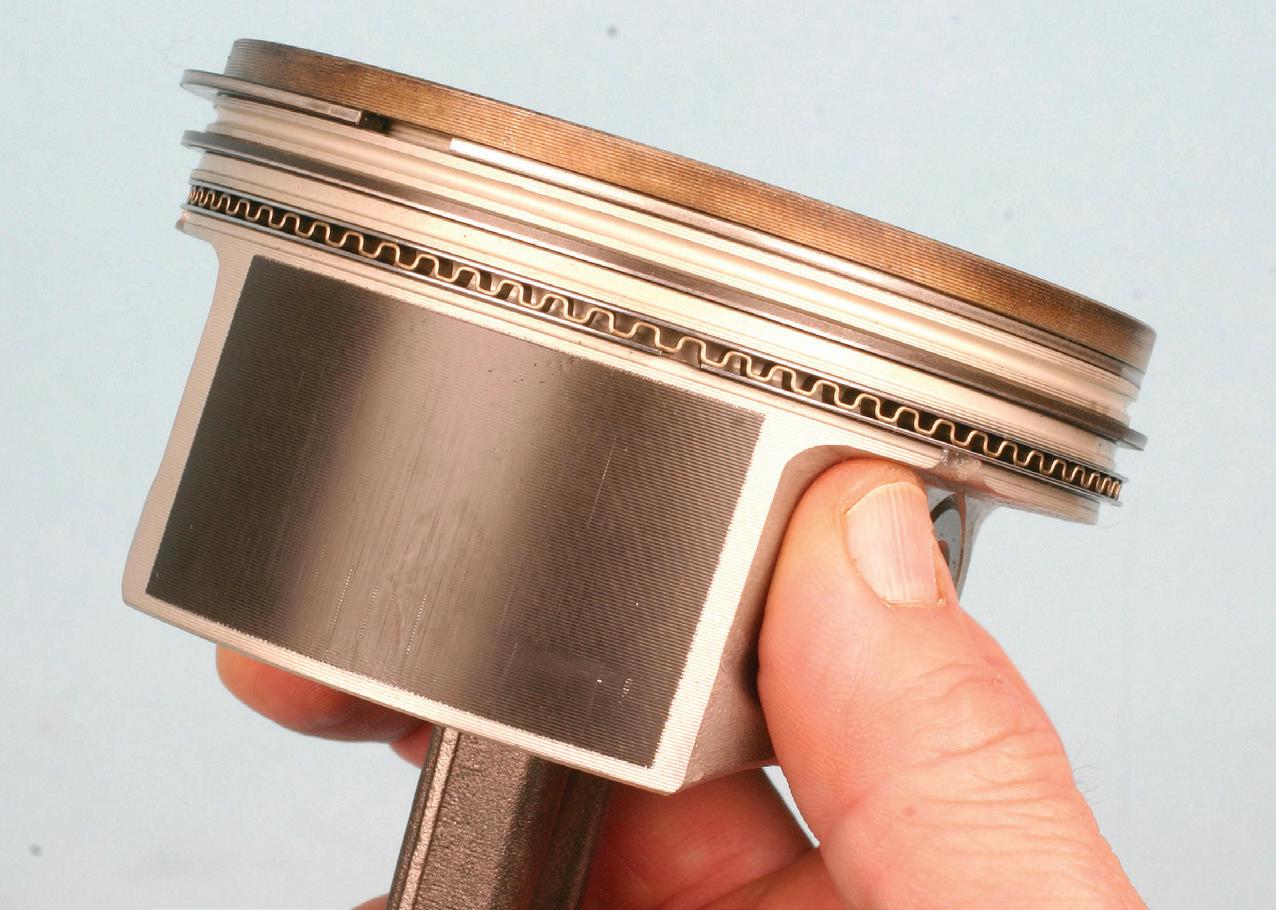
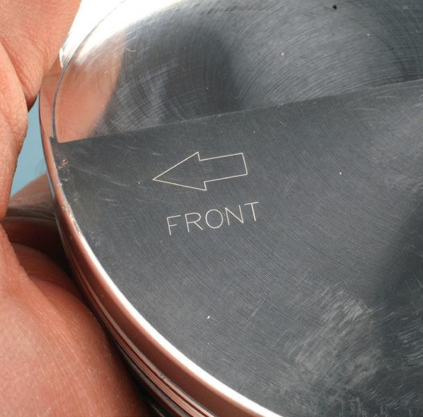
it’s critical to install the piston with this mark facing the appropriate direction. The mark indicates which side of the piston is intended to face forward.
As noted earlier, the minor thrust side is forced to the opposite side of the cylinder wall as it moves up on the compression stroke, due to the resistance generated by meeting the air/fuel mixture. The role of the minor thrust side is basically to provide piston stability, with the major thrust side taking the brunt of the cylinder wall contact. As a result, the minor thrust side skirt can be made narrower. This reduces piston weight without sacrificing strength and reduces friction within the bore.
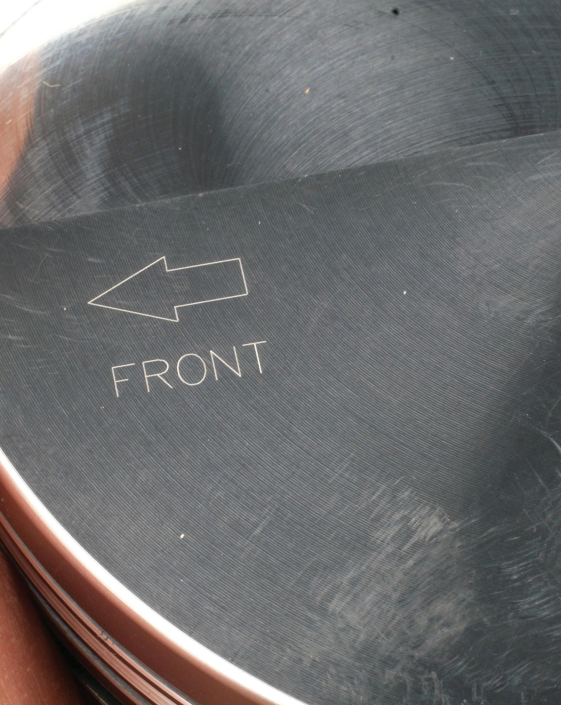
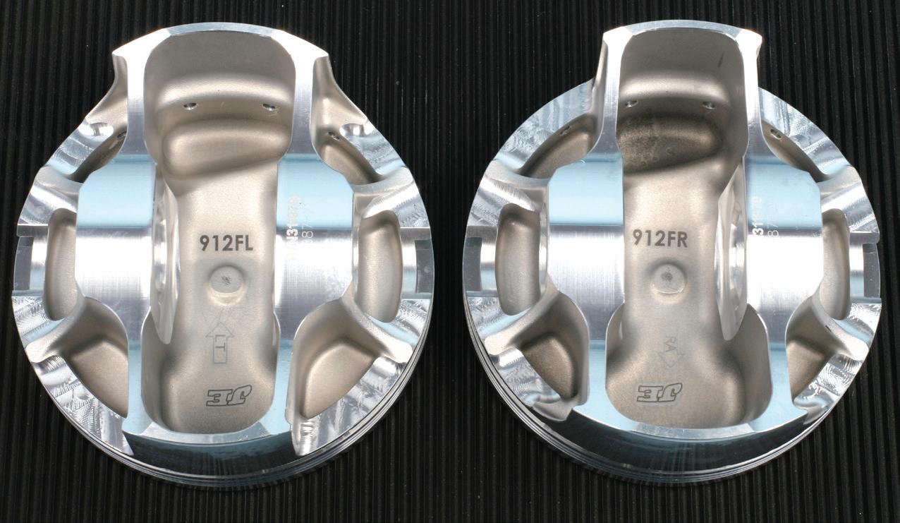
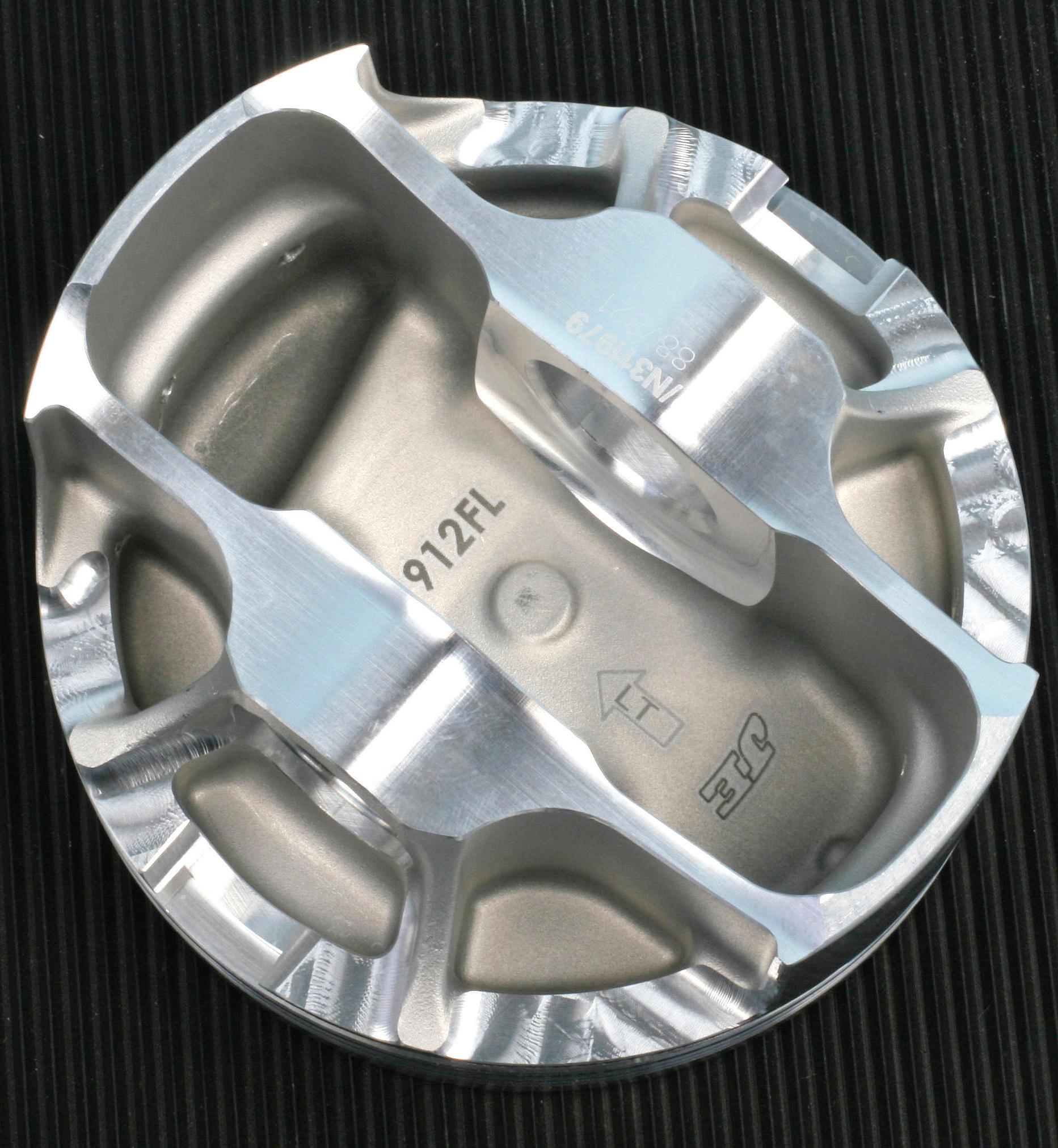
Some pistons feature an asymmetric design, where the major thrust side features a larger skirt, and the minor thrust side features a smaller skirt. Since asymmetric pistons are bank specific, each piston will be labeled for right or left bank position. The dome may also feature a laser-etched arrow that indicates piston orientation toward the front of the engine. The concept of asymmetric pistons was actually developed back in the 1960s by GM engineers. The design approach is now used by some aftermarket piston manufacturers, primarily targeted at the performance market.
The asymmetric approach provides an additional benefit: increasing piston ring sealing and ring stability. The dedicated major and minor thrust skirt design, coupled with a slightly offset wrist pin, directly addresses ring performance in addition to reduced wall friction.
It’s important to note that asymmetric pistons will also feature an offset wrist pin, with the pin centerline biased from zero toward the major thrust side by 0.020”. This slight offset tends to balance the piston to accommodate the difference in skirt mass and to compensate for and alter the effect of rod angle,





Motor Age Training offers the most complete and extensive ASE Training Series available anywhere
• Study guides
• Practice tests
• Detailed illustrations
• Available in your favorite format









transferring a bit of force away from the major thrust side. This allows the use of shorter, stiffer, and lighter wrist pins.
Some engines (some marine applications, for example) feature a reverse-rotation design where the crank rotates counterclockwise when viewed from the front of the engine. In those applications, the connecting rods are installed similar to a clockwise-rotation engine, maintaining the chamfered side of the rod big end facing the journal’s radiused fillet. However, if the pistons feature an offset pin, the piston must be installed “backwards” relative to installation in a clockwise engine. The pin offset is still biased toward the major thrust side of the piston. In a clockwise-rotating engine, the major thrust side is at the intake side on the left (driver) bank and the exhaust side on the right (passenger) bank. In a reverse-rotation engine, the thrust sides are opposite: the major thrust side will now be at the exhaust side of the left bank and the intake side of the right bank. If the pistons are symmetric (not asymmetric) and don’t feature an offset pin location, piston orientation won’t matter, as long as the valve pockets (if any) are located appropriately to the valve locations.

MIKE MAVRIGIAN has written thousands of automotive technical magazine articles involving a variety of specialties, from engine building to wheel alignment, and has authored more than a dozen books that crisscross the automotive spectrum. Mike operates Birchwood Automotive, an Ohio shop that builds custom engines and performs vintage vehicle restorations. The shop also features a professional photo studio to document projects and to create images for articles and books.
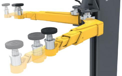
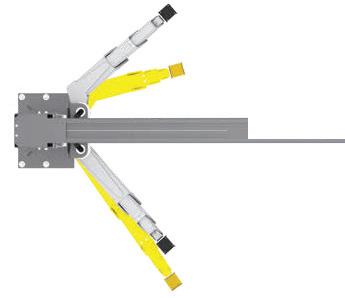
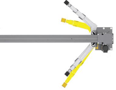
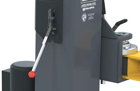
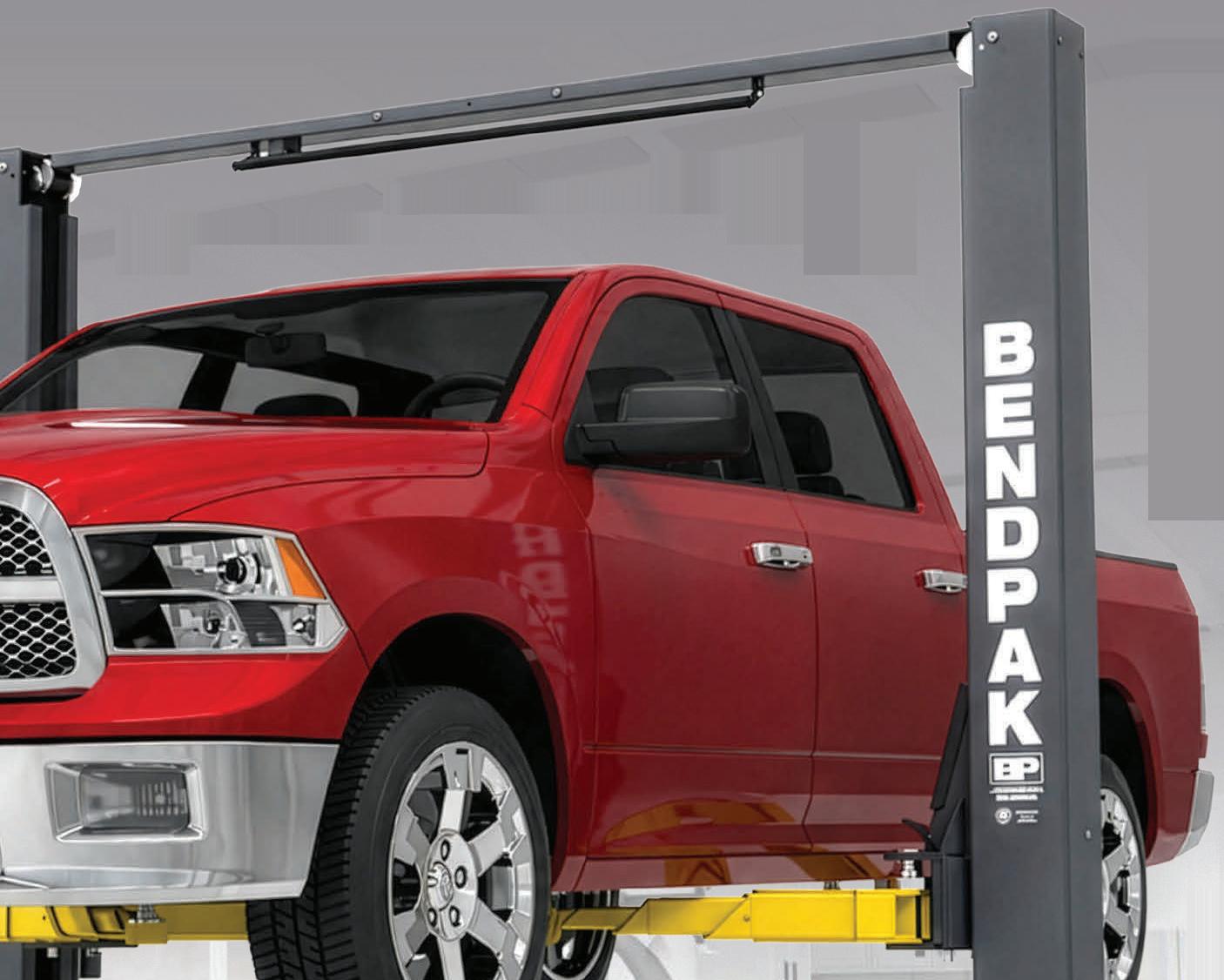
Two-post lifts are the most popular car lift type thanks to their versatility, affordability and ease of use. As a result, they come in a wide range of sizes and configurations. Let’s look at some size-related options using the BendPak AP Series as examples.
The most obvious difference among two-post lifts is how the posts are connected. In floorplate or “opentop” lifts like the BendPak 9APF, the cables and hoses run across the floor, usually under a cover plate. This design provides obstruction-free overhead lifting that’s great for low ceilings and tall vehicles. The columns in clearfloor lifts like the BendPak 10AP are connected across the top, usually with a top beam housing the cables and hoses that often includes an automatic lift shutoff if the vehicle contacts it. This design offers an obstruction-free work area under the vehicle.

Another visually obvious difference is overall (lift) height. This choice is usually dictated by shop ceiling height, the vehicles to be serviced, and the work to be performed. The BendPak 10AP stands a relatively compact 145 inches tall, but for shops with sufficient overhead clearance and the need to accommodate tall vans and work trucks, additional options can move the top bar up to three feet higher (10APX-181).
“Rise” is how high the lift carriage can go, while lifting height is the distance from the floor to the underside of the vehicle.
Short-rise lifts like the BendPak 10AP-SRT quickly position vehicles at about 46 inches high for tire service and detailing. A standard rise 10AP offers a max rise of 69 inches and 82.5-inch max lifting height. High-rise models like the 10APX with a max lifting height of 89 inches offer more vehicle flexibility and more workspace underneath for taller technicians.
The maximum capacity a lift is designed to raise and support should be clearly shown on its nameplate. Because it is
dangerous to overload a lift, be sure to choose one that has sufficient rated capacity for whatever vehicles will be serviced in the shop. While 10,000 lbs. capacity is generally plenty for passenger vehicles including cars, pickups and SUVs, shops that handle commercial vehicles may need 12,000 pounds or more of lifting capacity. The heavy-duty BendPak 20AP, for example, is rated for 20,000 lbs. It can take on medium-duty trucks, step vans, motorhomes, day cab tractors, utility trucks and more.
Don’t rush the lift selection process. Take time to make sure a new lift will fit in the space you have and do what you want it to do. Evaluate the latest features and technology. Finally, don’t skimp on safety. Always choose a lift that has been ALI Certified to meet industry safety and performance standards.


How they work, how they fail, and why software, calibration, and tire condition now matter as much as the transfer case itself
BY JEFF TAYLOR
Four-wheel drive and all-wheel drive systems on domestic light trucks and sport utility vehicles have changed a lot over the years. What used to be a mostly mechanical driveline with a transfer case, propeller shafts, differentials, and axle shafts now depends much more on clutch packs, electric motors, hydraulic control, and software strategy. Because of that, diagnosis is no longer as simple as looking at the transfer case or rear differential and blaming those components. On these systems, component layout, control strategy, sensor data, and setup after repair can all affect how the vehicle works.

It helps to start by looking at an older traditional truck-based 4WD system because it shows the basic driveline problem these systems have always had to deal with. In a part-time 4WD system, the transfer case locks the front and rear drivelines together, so both axles are forced to pull at the same time. That works well on snow, mud, gravel, and other loose surfaces because the tires can slip enough to relieve driveline stress. On dry pavement, the problem shows up quickly. The front and rear axles don’t turn at the same speed during normal driving, especially in a turn, so the stress stays in the driveline instead of being released through tire slip. That’s when the technician may hear complaints about binding, crow hop, chatter, or a vehicle that doesn’t want to turn smoothly.
Full-time 4WD, sometimes called permanent 4WD, was one of the first real ways around that problem. These systems still use a transfer case, but they also use a center differential or another method that allows front-to-rear speed difference. That lets the vehicle drive all four wheels continuously without forcing both drivelines to stay locked together on dry pavement. On truck-based sport utility vehicles, this made the system much more road-friendly while keeping the basic truck-style driveline layout of a transfer case, propeller shafts, and axle assemblies.
Just so the difference is clear: truckstyle permanent/full-time 4WD uses a transfer case and usually includes 4-Lo, while AWD is generally on front-wheeldrive SUVs or crossover vehicles and doesn’t have low-range gearing.
That difference in drivetrain design directly affects how the system is diagnosed. On a truck-style system, the technician is usually thinking about transfer case operation, shift motor function, encoder position, front axle engagement, range selection, and mechanical bind. On a FWD-based AWD system, the thinking has to change. Now the vehicle may have
a power transfer unit bolted to a transaxle, a propeller shaft going to the rear, a rear drive unit, a clutch pack, a hydraulic pump, actuator motors, and a control module making decisions from wheel speed, steering angle, throttle position, and vehicle dynamics data.
Differentials still sit in the middle of every 4WD and AWD system, and they matter more than many people give them credit for. A basic differential allows the left and right wheels on an axle to turn at different speeds in a corner. In newer systems, the rear differential assembly may also be part of the torque management strategy or torque vectoring system, with clutch packs, hydraulic control, and its own electronic logic. The rear axle in torque vectoring systems does more than just send power to both rear wheels. The system can change the torque from side to side based on things like wheel speed, steering angle, and yaw. This lets it send more drive force to the wheel that can use it best. That usually means sending more torque to the rear wheel on the outside to help the car turn more naturally and stop it from understeering. Some systems use clutch control inside the rear drive unit to do this, while others use a brake-based strategy to change the transfer of torque. The goal is the same in either case: to use rear axle torque as part of the vehicle’s handling strategy to make it easier to grip the road, stay stable, and feel good when turning.
That means a rear differential complaint isn’t always a simple gear or bearing problem anymore. It can also be a clutch apply problem, a hydraulic issue, a programming problem, or a control problem.
Modern FWD-based AWD systems now make up a large part of the domestic crossover and sport utility market. Under normal conditions, many of these vehicles operate mainly as front-wheel drive. When rear torque is needed, the PTU redirects torque from the transaxle to a propeller
shaft, and the RDU applies that torque at the rear axle. That sounds simple until you get into how different these systems really are. Some use a single clutch pack to bring the rear axle online. Others use more advanced rear units that can control torque more precisely, including side-to-side control. Many are also predictive rather than purely reactive. In other words, the module may already be watching conditions and preparing the driveline before the driver ever feels wheel slip.
General Motors is a good example of how far these systems have gone. In the FWDbased layout, the PTU changes the direction of power flow from the transverse transmission to the propeller shaft, but the rear side is where the system gets much more involved. The rear differential clutch control module isn’t just turning the rear axle on and off. It’s watching the driving situation and deciding how much clutch application is needed to move torque to the rear wheels. That means the rear axle assembly is no longer just receiving torque. It becomes part of the vehicle’s traction and handling strategy. When a system like this has a problem, the complaint may not sound like a driveline problem at all. It may show up as chatter, bind, poor traction, odd engagement feel, or even something that sounds more like a handling issue.
The rear drive side on these GM systems also shows why technicians now must think about both electrical control and hydraulic operation. Rear axle engagement isn’t just an electrical command. The clutch control system uses a motor, pump, and solenoid to build hydraulic pressure so the clutch pack can apply correctly. Because of that, a weak or missing rear engagement complaint can be caused by many things besides the clutch pack itself. A pump problem, a motor fault, trapped air, a hydraulic issue, or a control problem can all create similar symptoms. This is where scan tool work matters. Looking at clutch motor data,
clutch engagement data, and system commands can save a lot of guessing.
as Much as the Parts Service procedures matter just as much as the actual components on these units. If the hydraulic circuit has been opened or air has entered the system during differential service, the bleed procedure must be performed. On some units, clutch correction factors or classification values also must be programmed into the module after repair. The job isn’t finished just because the unit is bolted back in and filled with the correct fresh fluid. If the special scan tool bleed is skipped, or the module isn’t matched correctly to the hardware, the system can still set faults or operate poorly even when the mechanisms are fine.
That same shift away from purely mechanical thinking also helps explain why rear axle diagnosis on newer GM systems has become more complicated than it used to be. Rear axle faults can be misdiagnosed as a failed control module when the real problem is in the rear differential clutch valve or related clutch control hardware. There have also been cases where a highway-speed rear axle squeal or whine was corrected with a calibration update instead of hard parts replacement. On early Cadillac XT5 and GMC Acadia applications, rear clutch control strategy could even lead to excessive rear torque under the right conditions, enough to damage the rear propeller shaft. Those are good reminders that rear axle complaints on modern AWD systems aren’t always caused by gears, bearings, or a worn clutch pack.
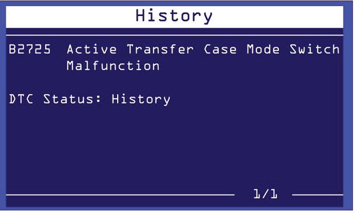
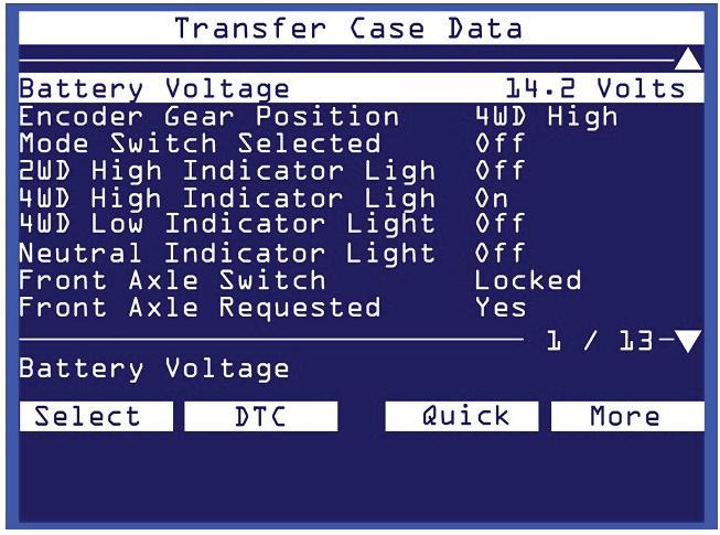
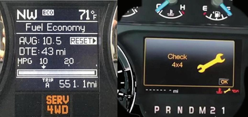
GM’s active transfer case systems on its newer trucks are a good example of how much 4WD operation has changed. In Auto 4WD, the transfer case isn’t acting like a simple locked system. The vehicle control systems are watching driving conditions and varying clutch torque to the front propeller shaft as needed. At low speed and light load, clutch apply stays lower, so the truck doesn’t bind or crow hop in tight turns. At higher speeds, more clutch torque can be commanded to improve traction and stability. That’s why Auto 4WD operation shouldn’t feel the same as a traditional 4HI mode.
Ford FWD-based AWD systems use the same basic PTU, propeller shaft, and RDU layout, but the strategy is worth understanding because it explains a lot of the complaints technicians see. On vehicles such as the Edge and similar platforms, the PTU can work in connected and disconnected modes to reduce drag when AWD isn’t needed. When rear torque is needed, the rear side is brought in first so the propeller shaft speed can be brought close to a match before the PTU dog clutch engages. That helps smooth the transition and reduce driveline shock. It also helps explain delayed or harsh engagement complaints, because if the rear side isn’t doing its part first, the final engagement isn’t going to feel right. On systems like this, it helps to stop thinking of the PTU and RDU as separate parts and start looking at them as one strategy.
Ford PTU service issues are also well known, especially on earlier units with no drain plug. Limited serviceability, high operating temperature, and fluid breakdown led to overheating, vent leakage, and strong odor complaints. By the time fluid is pushing out of the vent and the unit has been running on badly deteriorated lubricant, internal damage may already be there. That’s why service history matters. What looks like a sudden PTU failure
may be the result of long-term heat and fluid breakdown.
Ford also reinforces the point that the setup after repair matters. On some AWD systems, barcode entry, module setup, and required drive cycles are part of the repair. If those steps are skipped, the system may not respond properly even though the replacement work itself was done correctly. This is another area where modern driveline repair is no longer just mechanical work. Programming, calibration, and relearn procedures belong in the
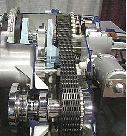
same conversation as gears, bearings, and clutch packs.
Jeep and FCA/RAM: Predictive
AWD Meets True Low Range
Jeep and other FCA/RAM systems add another mix because some of them combine AWD-type operation with a true low range. A Jeep system with an active twospeed transfer case can run in a 4WD Auto mode during normal driving, but it can also shift into a real low range for steep grades and off-road situations. That separates it
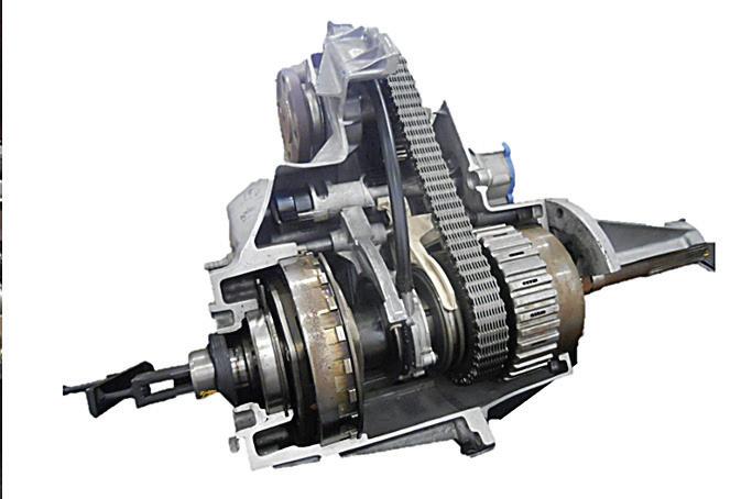
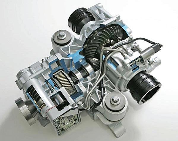
from many single-speed AWD systems. It also means the technician has to keep driver use in mind, because low range is still a specialized mode, and misuse can create complaints that aren’t being caused by failed parts.
Jeep drivetrain strategy is also a good example of how predictive these systems have become. Multiple driveline modules can watch wheel speed, steering behavior, load, and other inputs, then decide when the rear driveline should be brought in. In systems such as the Renegade, the rear driveline module can begin clutch apply in a controlled way, so the driveline is already spun up before full engagement occurs. The system also watches temperature closely. If clutch or motor temperature gets too high, the module may reduce AWD operation or shut it down completely to protect the hardware. That gives the technician a much better explanation for intermittent AWD loss after hard use. Sometimes the system is protecting itself, not actually failing.
Jeep also shows that hard-part failures still matter. Certain Cherokee applications developed known PTU spline failures, which is a good reminder that not every driveline complaint is software, calibration, or bad input data. At the same time, Jeep systems can also set service messages because of actuator or control faults that make the problem sound worse than it really is. That’s why it still makes sense to verify what the module is commanding before condemning the whole unit.
Don’t Overlook the Outside-the-Box Causes
One thing that keeps showing up across GM, Ford, and Jeep/RAM systems is that many 4WD and AWD complaints are caused by something outside the transfer case, PTU, or RDU itself. Wheel speed sensor problems are a good example. If the system depends on wheel speed data to decide when slip is present, an Anti-lock Brake System (ABS) fault can create what feels like a transfer case or rear drive problem. Tire circumference is another major
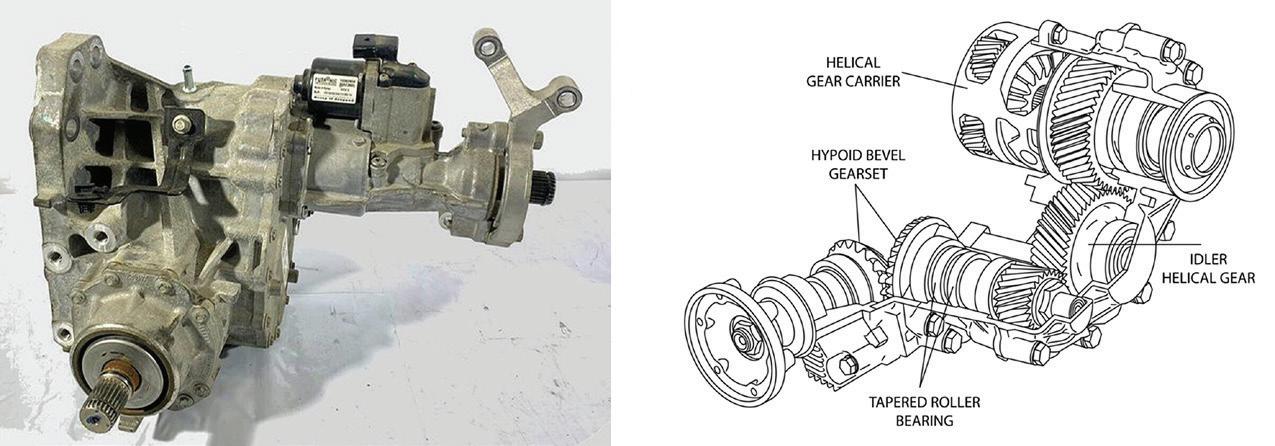
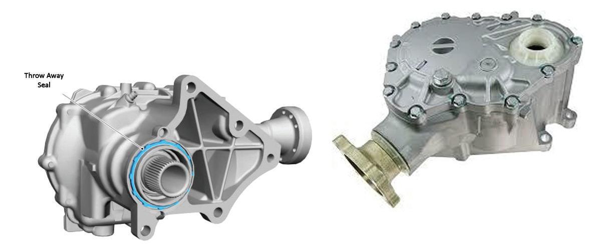
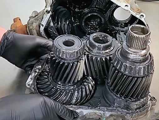
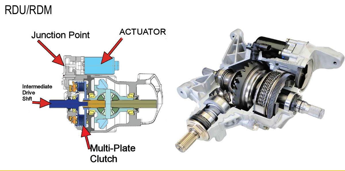
JEEP RENEGADE FWD-based AWD rear drive module (RDM) operation depends on actuator motor position feedback, internal temperature monitoring, and correct module programming. On these systems, the actuator motor and clutch assembly are a matched set, and clutch classification and energy specification values must be programmed into the Differential Transfer Case Module (DTCM) after RDM or module replacement.
TAYLOR
PHOTO CONTRIBUTED BY JEFF
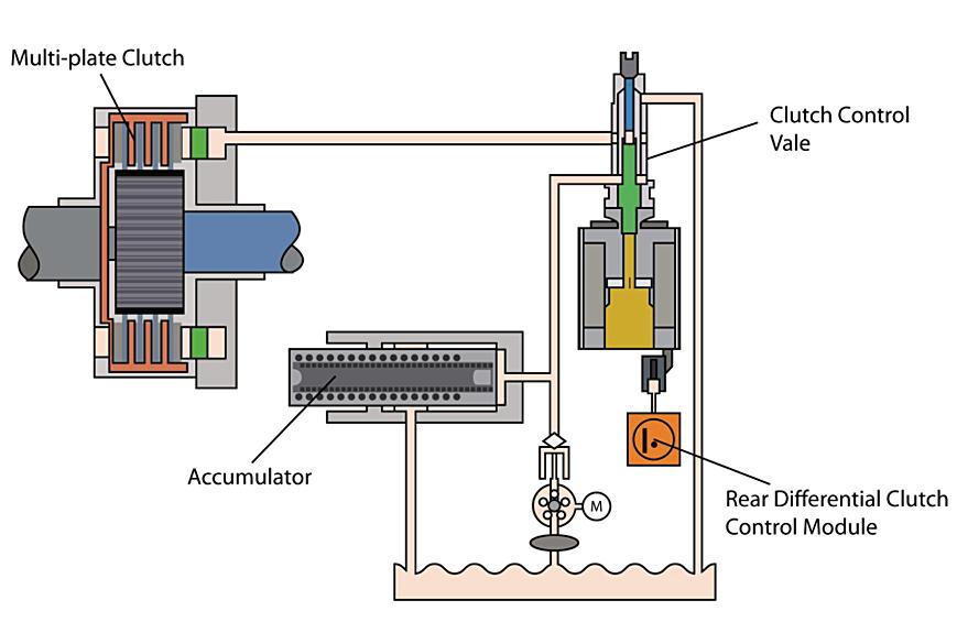
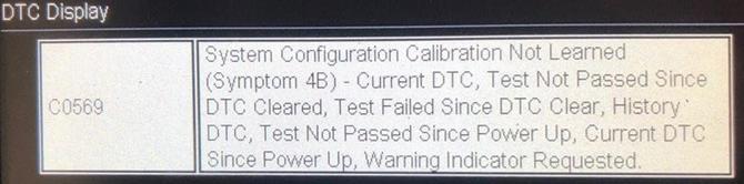
one. Even a small difference in tire size or tire wear can create the speed difference the module interprets as slip. Once that happens, the system may keep trying to correct a problem that isn’t really a traction problem at all. That can lead to overheating, bind, chatter, warning messages, and premature part wear.
Fluid condition is just as important. Wrong fluid, contaminated fluid, or fluid left in service too long can cause chatter, bind, noise, overheating, and eventually hard-part damage. That applies whether the unit is a Ford PTU, a Jeep rear driveline module, a GM rear clutch system, or a truck transfer case. Modern systems may be controlled by software, but the mechanical side still depends on clean and correct lubricant if it’s going to survive.
Diagnosing today’s 4WD and AWD systems takes more than knowing the major components. Transfer cases, differentials, PTUs, RDUs, and rear axle clutch systems still matter, but they’re only part of the operational picture. The real challenge is understanding system operation well enough to separate a mechanical fault from a control issue, a setup problem, bad input data, fluid trouble, or something as simple as mismatched tires. The basic driveline principles are still the same, but solving these problems now requires a full driveline-system diagnostic approach.

TAYLOR is a seasoned professional at CARS Inc. in Oshawa with 40 years in the automotive industry. As a skilled technical writer and training developer, he holds licenses in both automotive and heavy-duty vehicle repair. Jeff excels in TAC support, technical training, troubleshooting, and shaping the future of automotive expertise.
Customers walk in with a box, set it on the counter, and ask you to install it. Here’s how that one decision can quietly drain your margins—and what well-run shops do differently
BY NOAH NELSON
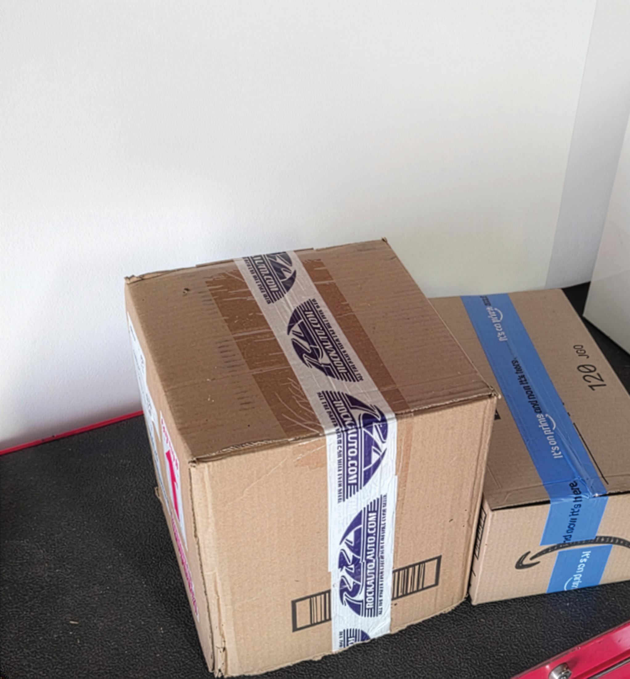
YOU ALREADY KNOW HOW THIS ONE ENDS.
A customer walks in with a cardboard box, sets it on the counter, and says the words every service writer dreads: “I already got the parts. I just need you to put them in.” A wheel bearing bought online for $42 with free shipping came in a plain white box with no brand name, and the seller’s address is somewhere overseas. Your tech installs it. Three weeks later, the car is back, the bearing is grinding, and the customer wants the repair done free of charge. He’s talking about leaving a review. And you can tell by the way he’s standing that the word “lawyer” is somewhere in the conversation, whether he says it out loud or not. Your shop never made a dime on that part. And now you’re looking at losing labor, time, and maybe a whole lot more. This is the customer-supplied parts dilemma, and if you work in automotive repair at any level, you’ve been here. The question isn’t whether it’ll happen again. It’s whether your shop is ready when it does.
Before we dig into everything that can go wrong, it’s worth taking a breath and acknowledging where the customer is coming from because most of them aren’t trying to be difficult. They’re trying to pay their bills.
When someone can pull up their phone and find a wheel bearing for $42 that your shop quoted at $120, that looks like a ripoff. It doesn’t matter that your price includes a quality part, a supplier warranty, and the ability to make it right if something goes wrong. From the outside, it looks like a $78 markup on a part, and that’s a hard sell in any economy. Add to that the general public distrust of repair shops, and you’ve got a customer who’s already skeptical before they walk in the door. Some of them have had good experiences with this. They bought a part, a shop installed it, it worked fine, and they saved $60. From where they’re standing, there’s no problem to solve.
Others are genuinely brand loyal. They want OEM, or they’ve used a specific brand for years, and they don’t trust that your shop will source the same thing. That’s a reasonable concern, even if it isn’t always accurate.
The point is that the customer’s motivation is understandable. What they don’t see is the risk they’re handing you along with that box. And that’s the conversation many shops avoid or handle poorly.
The numbers don’t work
Parts markup isn’t padding. That revenue funds the time your parts staff spends sourcing and receiving components, managing supplier relationships, handling returns when something’s wrong, and administering warranty claims when a part fails. Strip that out, and you’ve got a labor-only job with full exposure and compressed margins.
And that’s before the hidden costs kick in: time spent inspecting a part you didn’t order; time tracking down the missing hardware the customer didn’t know was sold separately; time figuring out, while the car is already disassembled and the old part is sitting on the bench, that the customer ordered the wrong application. That time isn’t free. You’re just not getting paid for it.
You don’t know what you’re installing When your shop sources a part, there’s a chain of accountability behind it. You know the supplier, you know the quality tier, and you stand behind what you sell. When a customer hands you a box they bought from an online marketplace, that chain doesn’t exist. Counterfeit and substandard parts are genuinely common in the online retail space. Convincing knockoffs of name brands fail at dramatically higher rates than the real thing. Parts that are technically the right part number but
manufactured to a standard that wouldn’t pass your supplier’s incoming inspection. And fitment problems are rampant. Customers order by year, make, and model without knowing about mid-year running changes, VIN-specific variations, or trimlevel differences that affect which part actually fits their car.
The tech finds this out while the car is apart. The job stops. The bay is tied up. The customer gets a call they weren’t expecting. And the whole afternoon evaporates while nothing billable is happening. A real example that happens every week: customer supplies a reman caliper. Tech unboxes it, gets it mounted, starts bleeding the brakes, and finds the bleeder screw threads are damaged. The caliper is junk. The car is apart. Reschedule. No charge for any of the time spent getting to that point.
Legal Side of This Is Serious
Who’s actually responsible when it fails?
This is the part that should keep shop owners and service managers up at night. When your shop installs a customer-supplied part, and that part fails, the liability question gets murky fast. The labor and the part are physically connected. In most failure scenarios, you can’t cleanly separate the two. Plaintiff’s attorneys know this, and they aren’t shy about it.
A signed waiver helps. It isn’t a guarantee. Depending on your state and the specific circumstances, a waiver may offer limited protection, especially if the claim involves professional negligence rather than simple product failure.
The duty of care problem
Here’s the part that surprises a lot of shop owners: courts have found that repair shops have a professional obligation to refuse parts they knew or should have known were unsafe or defective. That standard of care doesn’t disappear because the customer brought the part in. In some situations, it actually creates
more exposure, because the professional in the room is expected to know better. Work through the scenario: customer supplies a used rotor of unknown origin. The shop installs it. Six months later, it cracks at highway speed. Accident. The shop has a CSP waiver on file. The plaintiff’s attorney argues the shop had a professional duty to refuse to install an unverifiable safety component on a vehicle’s braking system. Whether that argument wins or loses, defending against it costs real money and takes real time.
Get your waiver right and know your policy limits
If your shop accepts CSP jobs, your waiver needs to be clear, specific, and signed before anything is touched—not buried in the back of a repair order, not mentioned verbally at pickup. Get it reviewed by a local attorney who knows automotive repair or warranty law. This isn’t expensive relative to the protection it provides. Also—and this one gets overlooked— call your insurer. Ask specifically how your garage liability policy handles customer-supplied parts jobs. Some policies have exclusions or complications in this area that shop owners don’t discover until a claim is filed. That’s a terrible time to find out.
Your labor warranty gets tangled up in a part you didn’t sell A standard shop warranty: 12 months, 12,000 miles on parts and labor. Customer supplies a part with no warranty, or a warranty that only applies to the original purchaser buying direct from the seller. The part fails at eight months. The customer comes back expecting it to be covered.
Now what?
If you didn’t explicitly exclude CSP components from your labor warranty in writing, you may be on the hook for the
part and labor to pull and replace the part—even if the part is clearly defective, even if you can’t recover anything from the supplier, and even if the customer no longer has the receipt to file a claim. Most of the time, the shop eats it.
The comeback will cost you more than you think
When a CSP part fails, and the customer returns, a technician gets pulled off a paying job. The bay is occupied. The scheduler is juggling. The service writer is managing an angry customer. Diagnostic time on a comeback is rarely compensated. The repair itself, if it falls under your warranty, is unbillable.
Budget three to five hours of unbillable time when a CSP comeback happens. That isn’t the worst case. That’s typical, once you count the initial diagnosis, the back-and-forth with the customer, the repair, and the administrative time cleaning up the paperwork.
Three Scenarios That Happen All the Time
These aren’t hypothetical. They’re composites of situations that happen in shops every week.
Scenario 1: The online deal that wasn’t
A regular customer brings in his truck for a hub assembly replacement. Already bought the part ($28)—a white box with no markings from an online marketplace. Tech installs it. Job’s done.
Eleven thousand miles later, the bearing fails. The customer comes back furious and blames the installation. Shop reviews the repair order: CSP notation is there, but no signed waiver, and the shop’s standard labor warranty is printed right at the bottom. The parts supplier’s terms say the warranty is void once a shop installs it rather than the purchaser. The shop is holding the bag. Two and a half hours of labor, a damaged customer relationship, and a hard lesson about getting signatures before starting work.
Scenario 2: Wrong part, car already on the lift
Customer schedules an O₂ sensor replacement. Already has the part. Looked it up herself. Tech gets the car in the air, starts working, and the sensor is the wrong application. Her VIN is the 2.4L. She ordered the 2.0L fitment.
Tech spends 45 minutes confirming the mismatch. The customer gets called, is initially defensive, and then apologetic. The job gets pushed. Bay time is gone. Nothing was charged. The customer comes back three days later when the right part shows up—no hard feelings, but the shop lost the better part of a halfday on a job that never happened.
Scenario 3: When it goes to an attorney
The customer brings in brake pads and rotors that he bought online. “Got a great deal,” he says. They look OK. The shop installs them. No waiver was pulled. Three months later, the customer calls about brake fade and noise. A week after that, a letter arrives from an attorney citing improper brake service and an unsafe vehicle condition.
The shop’s attorney reviews everything. There’s a standard disclaimer on the RO, but no CSP-specific waiver. The argument from the plaintiff’s side is that a professional shop had a duty to refuse to install unverifiable safety components. Whether the claim wins or not—and many of these settle regardless of actual fault—the shop’s insurer opens a file. Premiums go up. The service manager is dealing with this for the next eight months. The original job was billed at $180 in labor.
Pick a policy and stick to it
The shops that handle CSP jobs well have one thing in common: they’ve decided in advance how they’re going to handle it. They don’t wing it at the counter. There are three basic approaches:
• Refuse all CSP jobs. Clean, consistent, some customer friction. You lose a few jobs. The ones you lose are usually the ones that were going to cost you anyway.
• Accept CSP with conditions. Inspection fee, signed waiver, and explicit labor warranty exclusion on the supplied part. This is the most common approach among well-run independent shops, and it works if the policy is consistent.
• Case-by-case discretion. Only works if the criteria are written down and service writers are trained on them. Without documentation, every writer makes their own call, and the shop’s exposure is all over the map.
Have the conversation before the appointment
The CSP conversation needs to happen when the appointment is booked, not when the customer walks in with the box. If a customer calls to schedule and mentions they already have the part, that’s the moment. Service advisors should have a natural, practiced response, something like: “We can definitely take a look at what you’ve got. I do want to let you know that we charge an inspection fee on customer-supplied parts, and we don’t warranty the labor on those components. That protects you as much as us; if the part turns out to be defective, you’re not out the labor cost on top of it.” That framing is honest, it’s professional, and it puts the customer’s interests front and center. Most reasonable customers respond to it well.
Document everything
On any CSP job that moves forward: note the part brand, part number, and packaging condition on the repair order. Photograph the part and the box before installation. If the tech has concerns about quality or fitment, especially on safety-related components, those concerns go on the RO before the first wrench turns, and they get escalated to the service manager.
“I had a bad feeling about it” doesn’t hold up. “I documented my concern, and management made the call,” at least shows a professional process.
Most customers who bring their own parts aren’t trying to take advantage of anyone. They’re trying to get their car fixed without going broke. They looked up a part, found a price that seemed reasonable, hit buy, and they genuinely don’t understand the difference between that and what your shop sources.
That’s actually an opportunity. Shops that take five minutes to explain why professional parts sourcing matters—that the markup covers a real warranty backed by a real supplier relationship, that your tech is trained to spot a bad part before it goes in, that if something goes wrong, you can actually make it right—those shops build a different kind of customer loyalty. Some customers won’t hear it. They’ll go down the street to whoever will install anything without asking questions. You’ll lose the job. You won’t lose the three hours of unbillable comeback time, the waiver argument, or the attorney’s letter six months later.
Build the policy. Train the advisors. Protect your techs. And keep this in mind: the parts you didn’t sell can end up costing you more than the ones you did.

NOAH NELSON serves as technical editor for Motor Age. He started his 20-plus-year career as a lube technician and evolved through the ranks into district management. Now an ASE Master Technician, Noah leverages his diverse background to provide the industry with practical, real-world technical tips, guidance, and insights.
A simple sonic test reveals whether your block is salvageable— and how much material you can safely remove
BY MIKE MAVRIGIAN
IF A CUSTOMER’S ENGINE REQUIRES A REBUILD that may involve a cylinder bore over-sizing (overbore), inspection of existing cylinder wall thickness is always a good idea to determine if oversizing is possible or practical. Depending on the specific engine block design and the extent of cylinder wall damage to be corrected, isolated areas of the cylinder walls may be very close to the water jackets. If enough material is removed, this can weaken the cylinder wall and/or open the cylinder to water.
Since many repair shops may not be equipped to perform engine block reconditioning in-house, such work would likely be farmed out to a local engine machine shop. It’s preferable that the machine shop of choice can measure existing cylinder wall thickness. While this may
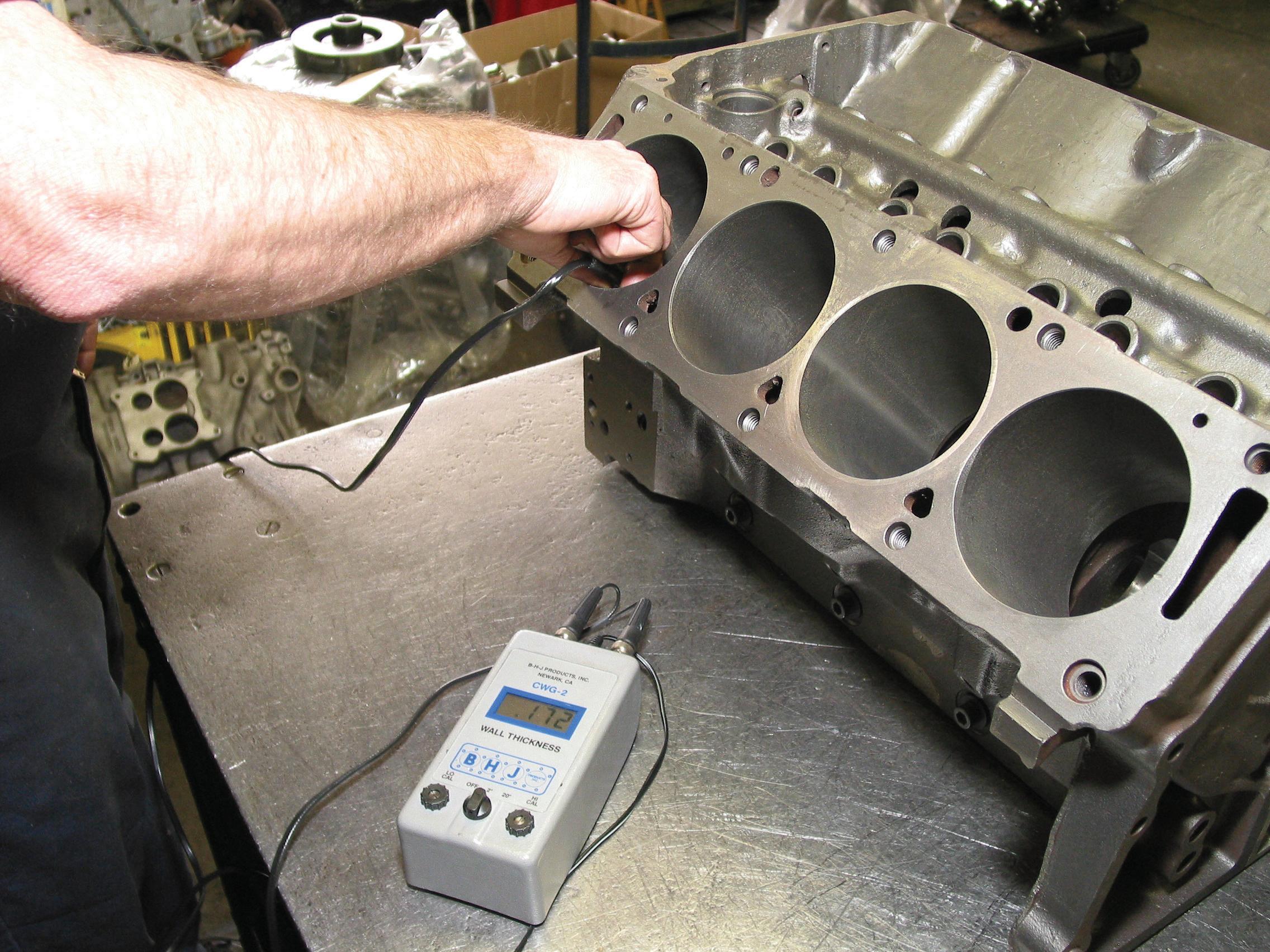
not be necessary with all engine blocks, being able to verify that the amount of material to be removed serves as a safeguard before the work. Knowing how much wall thickness is available up front can determine if the block is salvageable.
Wall thicknesses in newer engines are thinner than in the past, and checking castings before boring oversize or removing major amounts of metal is sometimes advised. Besides basic thickness, castings are subject to variations in manufacturing called “core shifts.” That is, sand cores forming the interior of hollow castings shift in position during the pouring of the casting, resulting in walls that are thick in some spots but thin in others.
Core shifts make themselves known in various ways. First, engine failures result from cracks in thin cylinders. Machinists may break into water jackets while boring. The most common difficulty encountered in obtaining roundness during cylinder honing. In this last instance, cylinders flex and allow the cylinder hone to pass by without removing the normal amount of material. While not all engines have these problems, they’ve become sufficiently common to cause machinists to find ways of inspecting casting thickness.
Ultrasonic testing is the accepted way of precisely measuring wall thicknesses. The tester transmits a sound wave through the casting wall, and the time required to pass through the wall translates into a measurement of thickness. This is possible because the sound waves don’t travel through the air on the other side of the wall. For example, where core shifts are involved, instead of a consistent 0.160” wall thickness, thicknesses may range from as thin as 0.060” to 0.260” (1.5 to 6.6 mm).
A sonic tester is an electronic thickness gauge. The tester (after being calibrated for the type of material being tested) features a remote probe. The

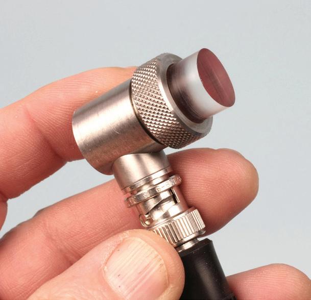
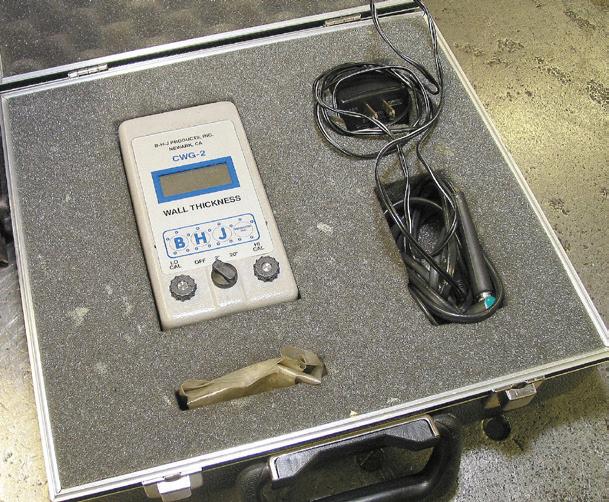
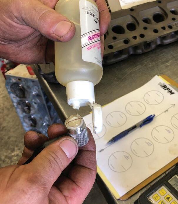
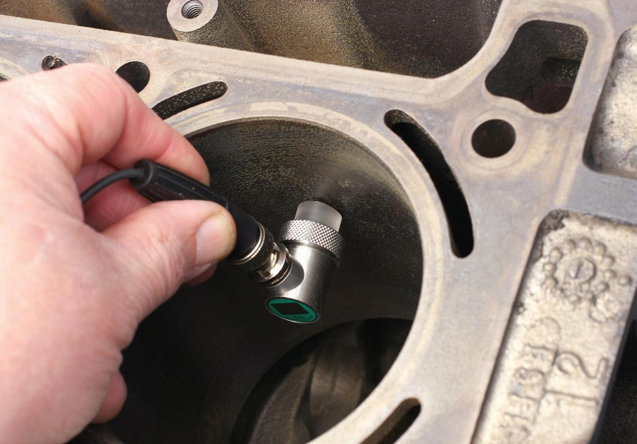
probe is placed against the material to be measured. The probe sends a sonar-type signal through the metal. When the signal reaches the backside of the material, the signal wave bounces back, electronically registering the material thickness. This is the accepted method of accurately measuring the thickness of an engine block’s cylinder walls.
Knowing how thick the cylinder walls are (at all height and radius locations within the bore) gives you an informed picture of how much material can be removed until you get too thin or hit a water jacket. For example, on a Gen V or Gen VI 454 or 502 Chevy block (water jackets run around each cylinder), minimum wall thickness is 0.090” (in the top 1” of the bore area, where thickness is most critical due to cylinder pressures). This 0.090” is a ballpark minimum. To be safe, a minimum of 0.125” in the top 1” of the bore is a much more acceptable minimum. Once you travel lower in the bore, cylinder pressures diminish considerably, and wall thickness becomes slightly less of a concern. Unless the cylinder walls have been cast incorrectly, you should have plenty of material in the upper portion of the bore.
If you plan to overbore the cylinders, using a sonic tester can verify that you have enough material to work with, or it can tell you that you have a thin spot that makes overboring impractical. It’s good to know this beforehand to avoid boring a block that can’t take the necessary wall thickness removal.
Assuming that your shop farms out this level of engine rebuilding, if your local machine shop doesn’t have access to a sonic tester, it’s a really good idea to bring the block to another shop that has a tester just to get the wall thicknesses gauged before you go any further in terms of time and your customer’s money.
Using a Sonic Tester: Step by Step Using a sonic tester is fairly simple.
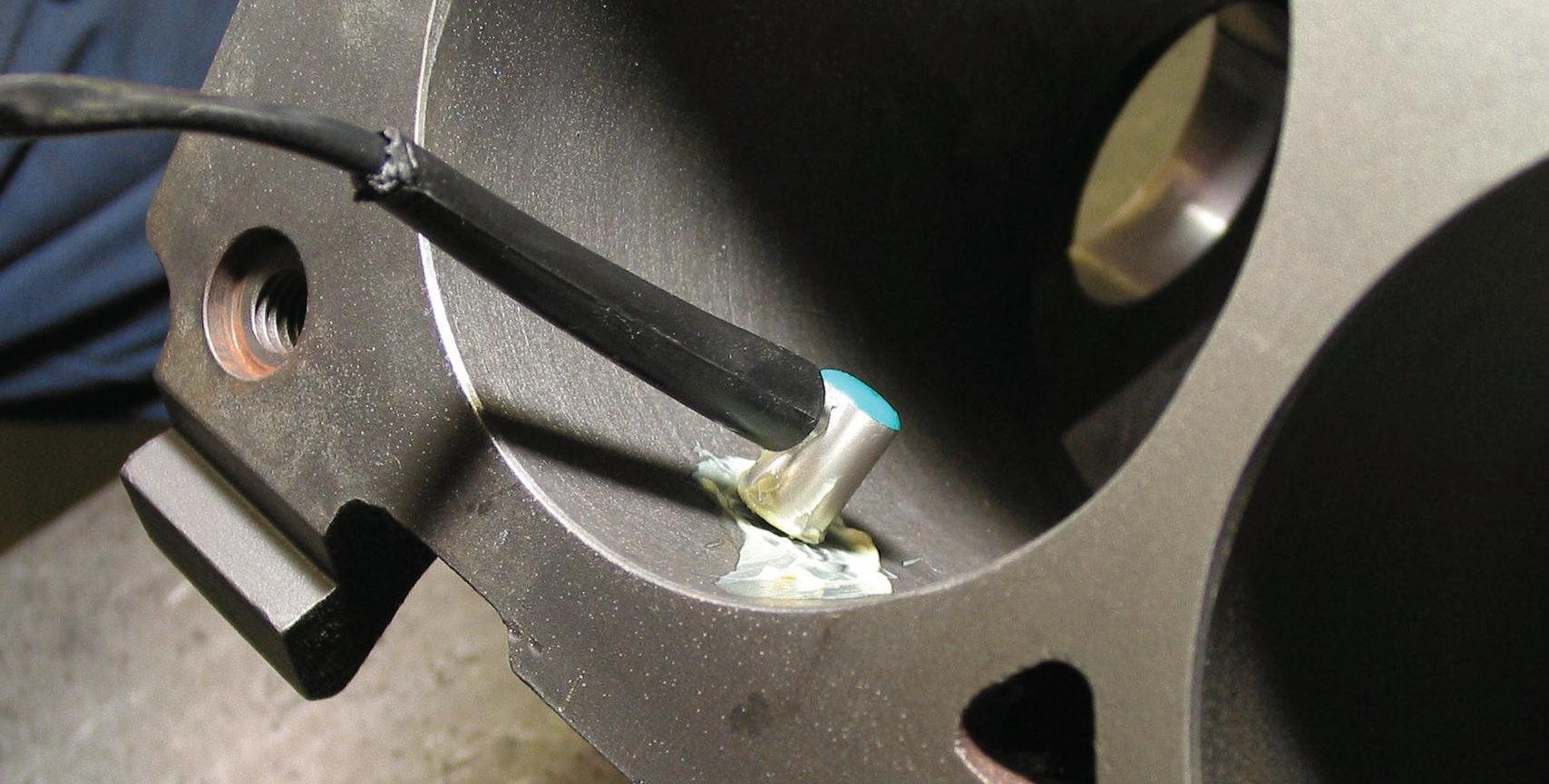
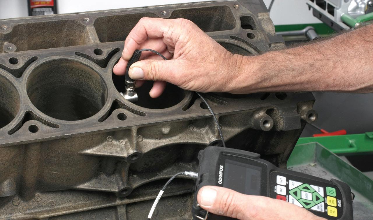
• First, the unit is calibrated using a precision stepped calibration tool (this is a precision-milled piece of steel that has been milled to 0.200”, 0.300”, 0.400”, and 0.500” thicknesses).
• The probe is plugged into the unit, the unit is turned on, and a small dab of lithium grease is applied to the face of the probe (the grease helps to gain better contact for a more accurate reading).
• While applying moderate pressure against the probe (pressing the probe and calibration metal together) at the 0.200” thick area of the calibration piece, adjust
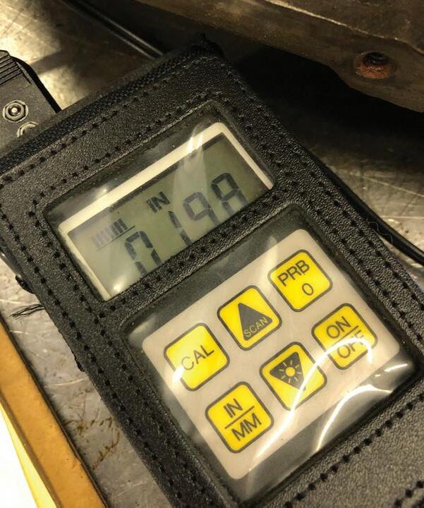
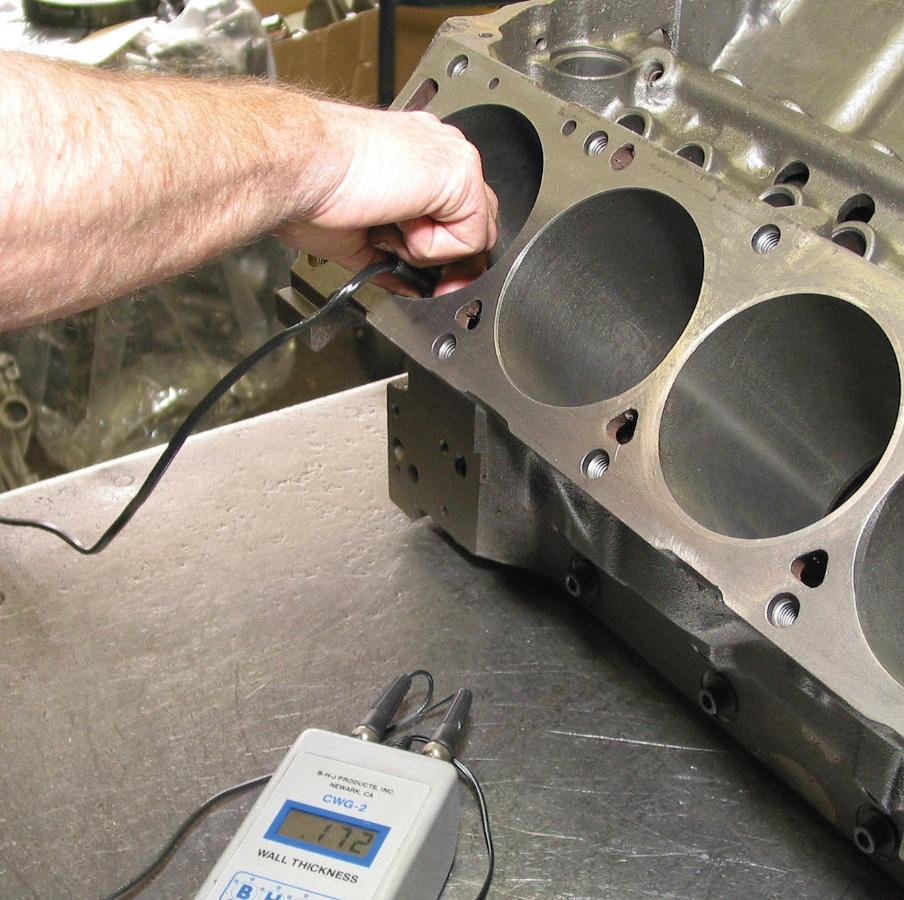
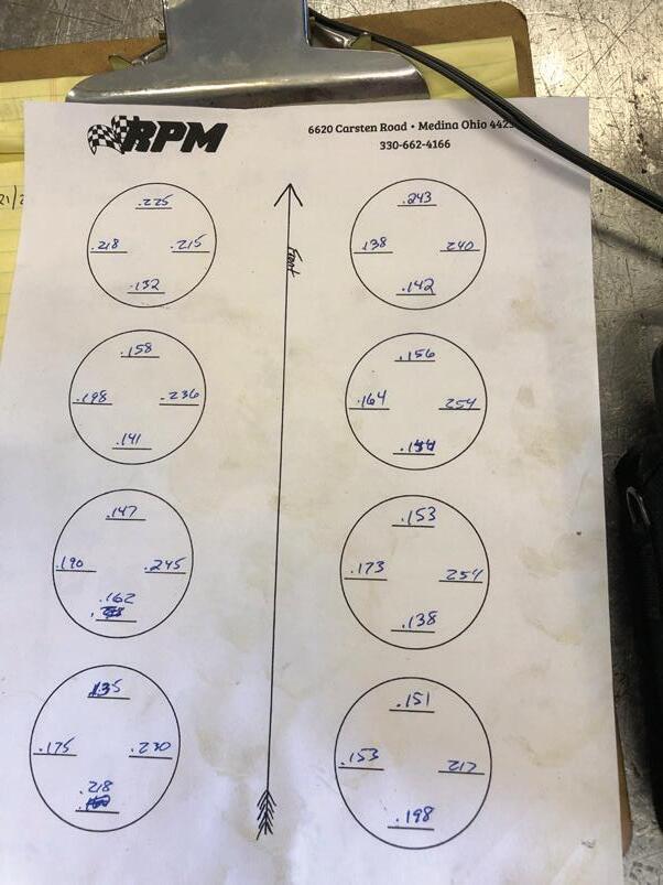
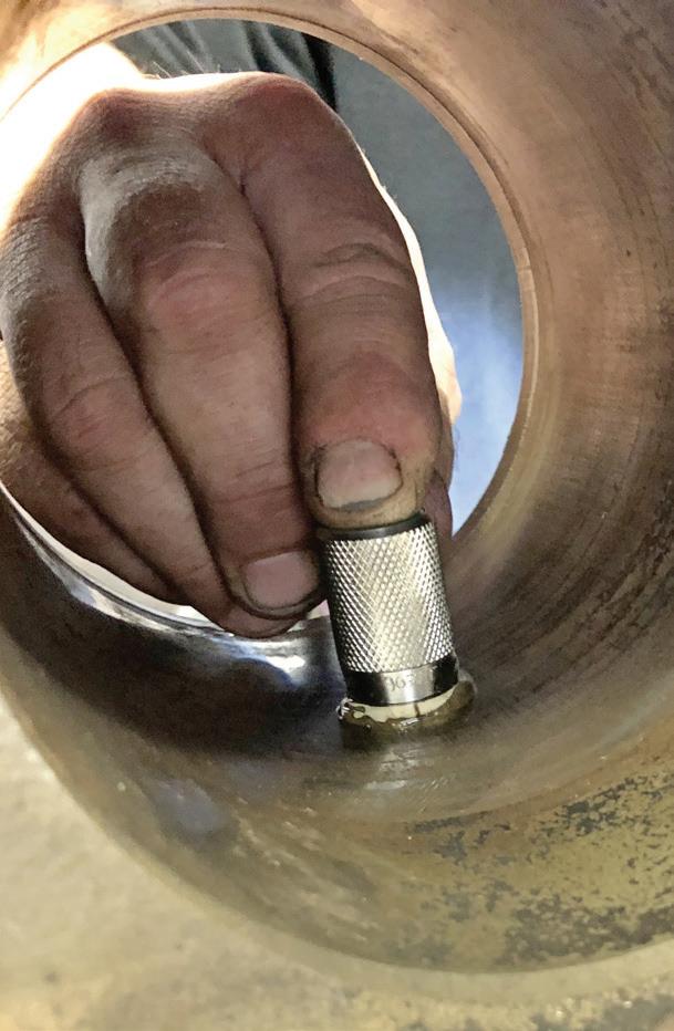
the “low cal” knob until the reading reveals exactly 0.200”.
• Finally, place the probe against the 0.500” thick area of the calibration piece and adjust the “hi-cal” knob until the reading shows exactly 0.500”.
This procedure should be repeated several times until the readings are stable. The sonic tester is then ready for use.
Clean the cylinder bore with a clean rag. Place a fresh dab or smear of lithium grease onto the probe face, and place the probe against the cylinder wall in the area you want to measure (apply moderate pressure against the probe). For best results, the probe should be placed at a 90-degree angle from the length of the cylinder.
Measure all cylinder areas, starting at the top (measure all the way around the bore diameter, in phases from top to bottom), noting and recording the wall thickness as you go. Since castings (especially OE castings) commonly feature some variation from bore to bore (in terms of thickness), it’s best to measure all eight bores. If you find a thin section, it’s better to know this now rather than after performing hours of expensive machining time.
MIKE MAVRIGIAN has written thousands of automotive technical magazine articles involving a variety of specialties, from engine building to wheel alignment, and has authored more than a dozen books that crisscross the automotive spectrum. Mike operates Birchwood Automotive, an Ohio shop that builds custom engines and performs vintage vehicle restorations. The shop also features a professional photo studio to document projects and to create images for articles and books.
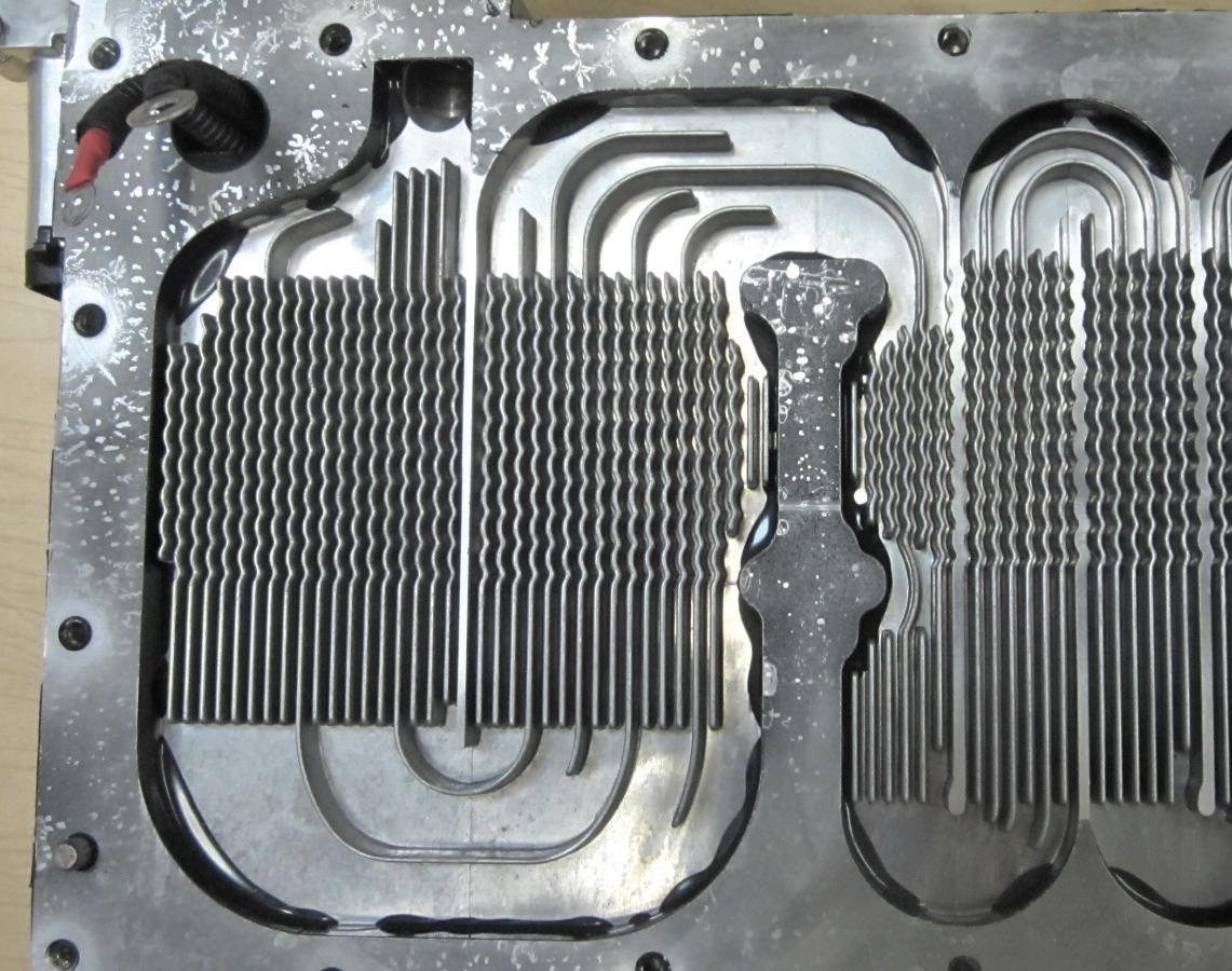
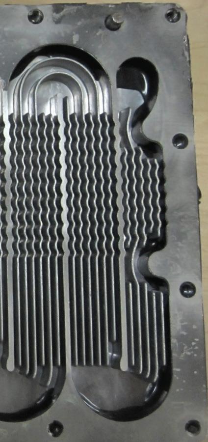
From
battery
cooling
to
cabin insulation, thermal management is becoming one of the most critical technologies shaping the future of electric vehicles
BY CRAIG VAN BATENBURG
THE ELECTRIC VEHICLE MARKET has advanced over the last 15-plus years in America, and the older systems have changed. Many more efficient technologies have found their way into newer designs. I live in Central Massachusetts, and it was a very frigid winter. ACDC, our EV technical training center, added a heat pump system to our 4,000-square-foot training lab a few years ago. The heat pump company that installed the system had only worked on homes. The system could not keep up with last winter’s arctic weather. I learned a lot about heat pumps for buildings, and some of that knowledge can transfer to vehicles, so there is more work to do and lessons to learn.
ACDC started teaching heat pump systems in 2013 when Nissan added a heat pump to the Leaf. Since then, that technology for heating the cabin has come a long way. Humans like to warm up on cool days and cool down on hot days. A high-voltage pack is organic. It is a lot like us.
Vehicle performance and range are the main qualities that continue to drive reinvention. Many technologies compete for development dollars, but few components surpass the battery in importance, with cabin heating in the second spot.
Humans like to warm up on cool days and cool down on hot days. A high-voltage pack is organic.
Keeping an EV’s battery cool is necessary for performance and longevity. This technology has continued to evolve alongside the other sophisticated technologies present in modern electric ve -
hicles. We’ll discuss the importance of thermal management in EV batteries, how it’s currently designed, the limitations of each method, and solutions being developed.
We know that all batteries lose their ability to do work when they are outside in the cold, and electronics don’t like heat. All batteries perform best when they are not subjected to extreme temperatures. The temperature most batteries require for optimal performance is between 65 degrees Farenheit and 80 F. It may seem surprising that the optimal temperature for an advanced electric vehicle battery exists within such a narrow range. Considering how temperatures can vary from one season to the next, it’s tempting to question why anyone would use an electric vehicle in all but the most temperate climates. Fortunately, onboard thermal management systems are used to control EV battery temperatures, thus improving performance and lifespan.
TMS in electric vehicles doesn’t just help lessen the effects of a hot or cold day on the vehicle’s battery; they also play a key role in managing the elevated temperatures generated by the batteries themselves. Lithium-ion cells become unstable and can catch fire when internal cell temperatures exceed 140 F to 190 F Some lithium-ion chemistries can go as high as 194 F. Once ignited, these cells can reach extreme temperatures, often between 2,000 F and 5,000 F Scary stuff.
An EV battery needs to keep cell temperatures below 140 F to 280 F. You have all heard the term “thermal runaway,” a condition in which a battery’s lithium-ion cell enters an uncontrollable self-heating cycle.
Plugging into a fast-charging station will also heat the battery to a point where the thermal management system will need to intervene. The high current generates a considerable amount of heat that needs to be removed from the battery pack to avoid overheating. Thermal management isn’t just about dissipating heat; depending on the time of year, there may be times when an EV’s battery must be warmed up before it can be charged quickly.
Thermal management processes, like anything else, are not perfect. Like any other system within an electric vehicle, thermal management is not without its challenges.
If the TMS uses liquid cooling to keep the battery at the optimal temperature, there is a chance that the liquid coolant can leak as the connections and battery age. While a small coolant leak sounds like a minor issue, if left unchecked, leaked coolant can degrade the battery to the point where its performance and lifespan are greatly reduced.
Corrosion, clogging, and coolant
Corrosion and clogging are two more challenges of a liquid-cooled system. Where liquid glycol is present, as it gets older, it can begin to corrode the cold plates, which are responsible for the transfer of heat from the cells to the coolant. Replacing the glycol as part of the regular maintenance of the vehicle will prevent this from happening.
Clogging the many narrow tubes and connections that transport the coolant is another challenge that could reduce the performance of the battery. It’s therefore important to choose the right coolant for the system and to change it regularly.
For example, pure water as a coolant
works well because its use minimizes corrosion, and it has a high heat capacity and thermal conductivity. Deionized water, on the other hand, removes harmful minerals and salts that could build up, narrowing the many channels, but has higher resistivity than pure water.
Coolant resistivity measures its ability to resist electrical current, with high resistivity indicating pure, nonconductive coolant that protects against electrolysis and corrosion. As corrosion inhibitors deplete and contaminants increase, resistivity drops, and conductivity rises, indicating the need for replacement, particularly in electric vehicles. The higher the resistivity, the greater the likelihood of corrosion.
Dielectric fluids like perfluorinated carbons—perfluorinated compounds are highly stable, water- and oil-repellent chemicals featuring carbon-fluorine bonds—and polyalphaolefin, a
synthetic hydrocarbon base oil, can also be used to cool an EV’s battery, both of which offer several benefits over the other coolant types. Use OEM coolants when servicing EVs.
Climate challenges and battery self-regulation
The climate surrounding the vehicle is another obvious challenge that must be mitigated by the vehicle’s TMS. Depending on where the operator lives, the vehicle may be exposed to extreme heat or cold when it is not running. In these conditions, keeping the vehicle plugged into the grid is the best path to follow.
When that cannot be done, the HV pack will consume its own energy to self-regulate cell temperature. Tesla will send a text message to alert you to plug in your car if the pack is getting low in cold climates.
Aging batteries generate more heat Lastly, the age of the battery itself is a
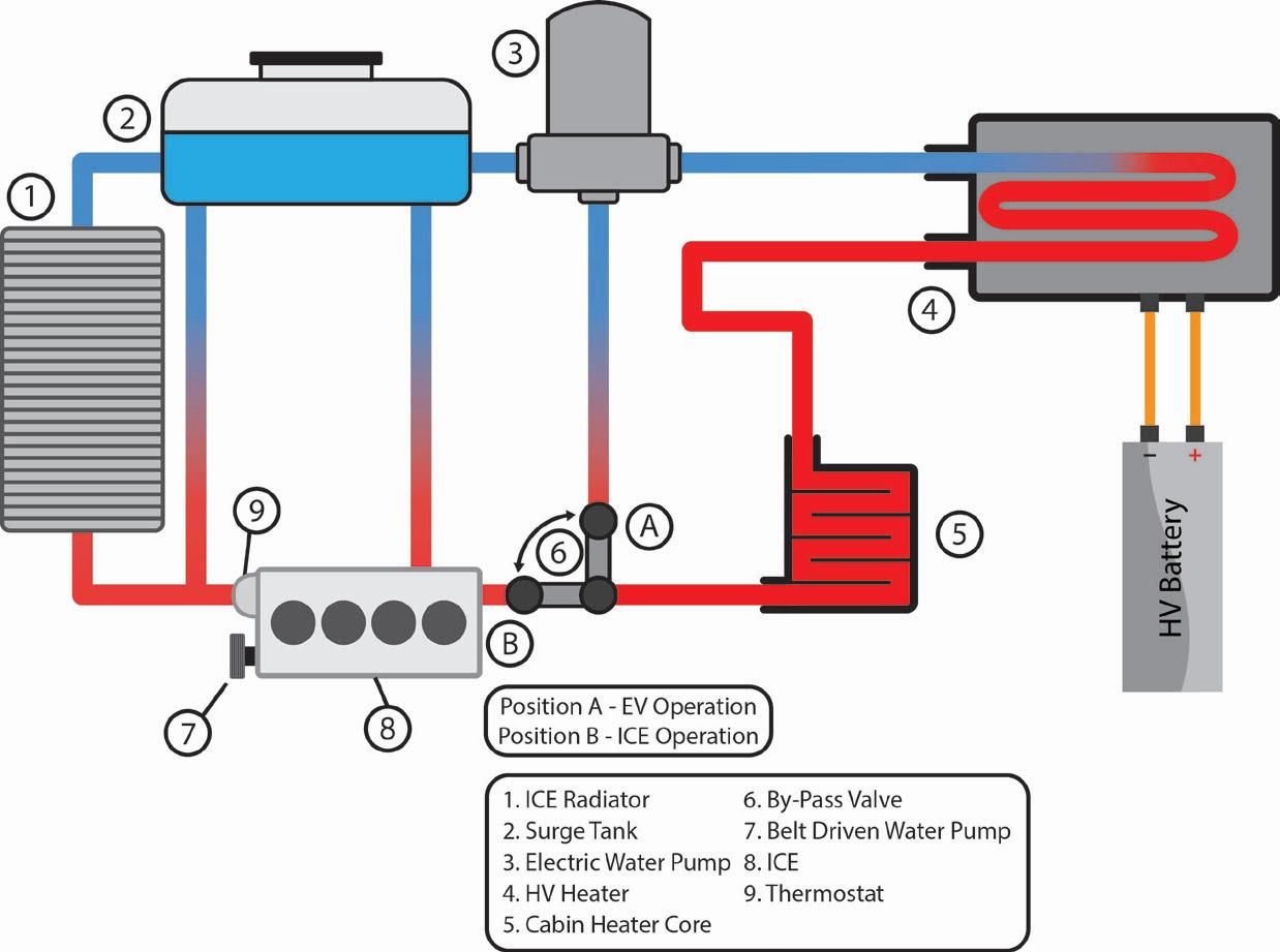

challenge to the thermal management system. The older the battery, the more energy is lost as heat. The system must be able to deal with this excess heat as the battery nears the end of its life.
So, how are EV batteries kept cool? We briefly referenced a liquid-cooled system above, but liquid is by no means the only—or even the best—method to keep an EV’s battery within the acceptable temperature range. Some of these methods are discussed below.
First, there are air-cooling systems, like the early hybrids. Air cooling worked OK, but Ford went with a sealed pack that was air-conditioned in model year 2005. Later on, Ford used cabin air. Depending on whether the battery needs to be warmed or cooled, warm or cool air is passed through the battery. In some air-cooled systems, cabin air is

circulated from the vehicle’s interior to the battery pack, warming or cooling the battery as necessary.
While this does sound like a novel and straightforward way to keep the battery’s temperature within an optimal range, it isn’t the most efficient option.
Liquid cooling systems rely on a series of channels to deliver liquid coolant in and around the battery packs in order to wick excess heat from the system.
Active liquid cooling uses pumps to circulate the coolant and fans and other devices to extract or redirect the heat. The glycol or water coolant does not come into direct contact with the cells.
It should be noted that while other systems within a vehicle may also require cooling, EV battery packs are cooled separately since the battery’s temperature must be kept much lower relative to the other systems. Keeping the cooling systems separate ensures the coolant responsible for managing the temperature of the EV battery is kept as cool as possible.
A battery that is too warm or too cold will negatively affect performance. Since EVs are expected to operate in all types of climates, the continued refinement of thermal management processes is vitally important to the growth of the EV market.
If electric vehicles are truly destined to surpass traditional combustion-engine vehicles, all EV technologies—thermal management included—must continue to evolve.
A lot has been written about heat pumps, but less about insulating the cabin. It can keep the inside warmer
in winter and improve range. Some DIYers have tried to insulate their EVs.
Low-e glass and interior insulation
Some OEMs have played with removable interior polycarbonate panels. Others opt for low-E (low-emissivity) glass. This is a type of energy-efficient glazing coated with a microscopically thin, transparent metal or metal oxide layer used on windows.
It acts as a thermal filter, reflecting heat back to its source. This keeps interiors cool in summer and warm in winter while allowing natural light
to enter. This reduces heat gain and loss by improving thermal insulation. The transparent coating is 500 times thinner than a human hair, keeping the glass nearly colorless and clear. A “hard coat” is fused to the glass during production. A “soft coat” is applied in a vacuum chamber and is more effective. It is much more effective in double- or triple-pane insulated glass units (IGUs).
Low-E glass is widely used in residential and commercial windows to improve insulation and reduce reliance on heating and cooling systems.
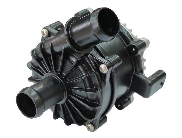
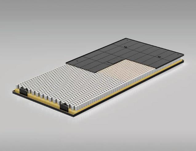
It is possible for Teslas to be retrofitted with this type of glass roof. Using heated seats and steering wheels is more energy-efficient than heating the entire cabin, but you can do more. If you have an EVSE at home or work, you can pre-warm the car’s interior and battery while it is still plugged into the grid.
Insulation and in-cabin modifications help retain heat, allowing for comfortable temperatures with less energy consumption.
In Worcester, Massachusetts, my hometown, a company called Talbert Trading, managed by Bob Mantyla, made shoddy. Bob gave me a tour to see how it was made. Two large French-made 60foot machines started with a hopper. Donated used clothing that did not sell was dropped in the hopper, and out the other end came an under-carpet felt mat commonly referred to as shoddy felt. It’s used for sound insulation and padding under the car’s carpeting. This was then shipped to the OEMs in Michigan in large rolls, three feet in diameter. That was in the ‘80s.
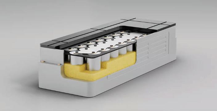
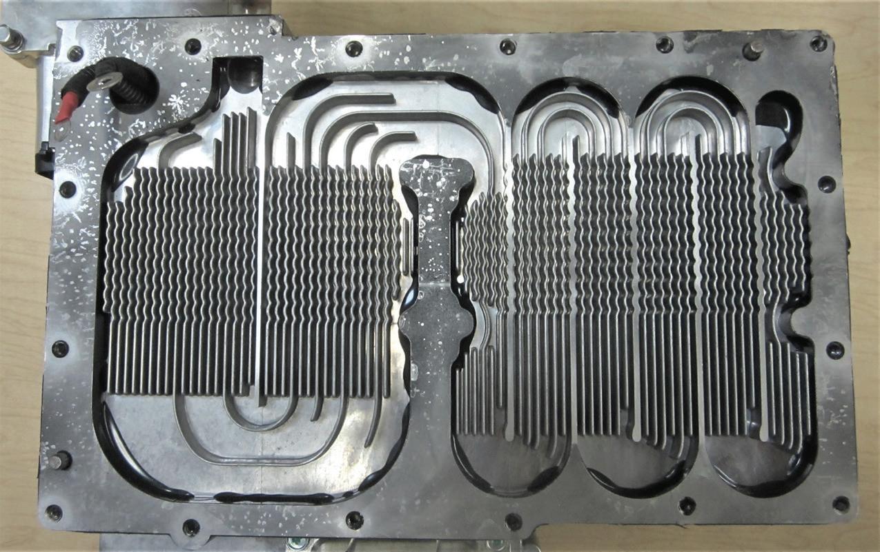
Today, that same concept is making its way into the cabin, but not just under the carpet. Everything that gets cold and is made of metal will be insulated. The firewall, roof, doors, under the rear seat—you name it.
A few years ago, at the SAE Congress in Detroit, Michigan, I had a chance to stop at a trade show booth that was offering a dense, shoddy-type material. It was more high-tech and a bit pricey. They had some statistics that made the case to use it.
Once you preheat the cabin while plugged into the grid, you can drive up to 20 miles before you need to turn on the heat. They did their own testing, but the concept is sound.
I have yet to see it in production cars, but every bit of energy used in freezing weather will reduce range.
If they go there, I sure hope they consider us, the repair techs. As the recent war in Iran has taught all of us, EVs make sense in many ways. Gas is expensive, and electricity is not.
Do not pass on the training you may need by staying away from high-voltage systems. It is your present job when the owner writes up an RO on an EV with your name on it.

CRAIG VAN BATENBURG is the CEO of ACDC, a hybrid and plug-in training company based in Worcester, Mass. ACDC has been offering high voltage classes since 2000, when the Honda Insight came to the USA. When EVs were introduced in 2011, ACDC added them to their classes. Reach Craig via email at Craig@ fixhybrid.com or call him at (508) 826-4546. Find ACDC at www.FIXHYBRID.com.

The TOPDON ONE is a 10.1” automotive diagnostic tool designed for technicians looking for fast, accurate, and reliable diagnostics. It delivers dealer-level capability with clear network mapping, smart repair guidance, and deep coverage across modern vehicle systems. With support for advanced protocols, coding functions, and the speed of dual-Wi-Fi architecture, the ONE aims to keep workflow moving. Additional features include ECU coding, one-click customization with pre-set options, OE-level topology, TopFix AI, 50-plus maintenance functions, J2534 pass-thru programming, support for CAN-FD and DoIP, coverage for mor than 120 brands.
The SUNEX Tools 3/8” Drive 84-pc Master Impact Bit Socket Set, No. 3569, mixes hex, star, external star, tamperproof, and triple square driver coverage with core impact socket service in one assortment. The 3/8” drive with SAE and metric coverage keeps standard socket work and specialty driver coverage together in one set. Designed to help technicians cover common impact socket and specialty driver interfaces.

The Milwaukee Tool 2-pc Comfort Grip Cutting Pliers Set, No. MT550-2, is designed to deliver the easiest cuts, engineered with an optimized pivot point for increased leverage for making cuts through materials such as ACSR, hard wire, and soft wire. The 9” Lineman and 8” Diagonal Cutting Pliers feature laser-hardened edges for extended cut life. The Lineman Pliers include a reaming head for 1/2” to 1” conduit and a fish tape puller for additional versatility. Pliers are tether-ready and offered in both dipped grip with a split-ring hole and comfort grip with a lanyard hole. Made in the USA.

The Snap-on Pass Thru Assistant+ is a J2534 programming device that combines the turn-key remote support offered by the Pass Thru Assistant with the DIY functionality of the Pass Thru Pro. This device offers J2534 flash programming services performed remotely by OE-trained technicians for domestic, Asian, and European vehicles. Users have access to OE-trained brand-specific master technicians to provide remote repair guidance for complex vehicle systems. ADAS support and calibration can be performed remotely by the team of specialists. Functions as a standalone J2534 vehicle communication interface when used with a PC and OE-purchased subscriptions.

The AUTOOL Digital Cylinder Pressure Gauge utilizes digital sensing technology and high-precision chips to display pressure values. Equipped with a one-way valve, it accurately locks the maximum pressure value of the cylinder. Comes with various connectors to support cylinder pressure testing for most engines on the market. Includes a data storage feature that records six sets of pressure measurement data, facilitating comparison and observation to identify fault points. Users can switch between pressure units psi, Bar, and kg/cm and temperature units Celsius and Fahrenheit. One-key data locking prevents accidental changes to readings. The HD 2.8” LCD backlight display ensures readability even in low-light environments. Comes with a toolbox for storage.
The FJC Inverter 400W, No. 53040, is designed to convert DC power into 120V AC power with multiple outlets. The inverter provides portable AC power for cars, trucks, RVs, and boats. Designed to be used with portable handheld tools. Additional features include a low battery alarm, overload protection, and short circuit protection. Connection cables and instructions are included.


Assembled in Conway, Arkansas, the Snap-on PolarTek Pro A/C Recycler, No. EEAC355, is designed to help shops stay productive year-round. The powerful two-stage vacuum pump supports deep, reliable refrigerant and moisture evacuations, while integrated nitrogen leak testing helps identify hard-to-find leaks and reduces customer callbacks. The extra-large filter dryer delivers up to 60% more service time between replacements, reducing downtime. A faster, more responsive touchscreen display and intuitive user interface simplifies operation, and supports consistent, efficient R-1234yf service in every season.
The Tool Aid Cylinder Leak-Down Test Kit, No. 33500, diagnoses internal engine problems like leaking head gaskets, bad rings, and defective valves. This kit comes with a top dead center whistle that can be connected to the testing hose. Dual 2-1/2” gauges with protective rubber boot read to 100 psi/7 bar. Test hose and gauges come with quick connect fittings for easy setup and use. A 0.04” orifice restriction fitting increases testing accuracy. Includes a 241/2” testing hose with 14mm end threads into 10mm, 12mm, and 18mm adapters. Comes packaged in a blow molded case.
The GripEdge Tools 9-pc RPT Long Metric Hex Key Set, No. LKHM9LS, is designed for deep or obstructed metric hex fasteners requiring extended reach and angled access. The patented RPT ball hex geometry allows for superior grip and 20-degree pivot capability. The extra-long bar length gives the user enhanced reach in recessed applications. Constructed from S2 tool steel with black manganese finish. Features a round bar design with knurled section for positive grip in wet or oily conditions. Large laser-etched size markings and Color-Eye-D coding. Locking, folding wallet-style holder with patented C-Grip slot geometry for secure retention and precise removal.
The Carlyle Tools 1/2” Drive Air Impact Wrench, No. CPTIW12PB, delivers up to 1,700 ft-lbs of breakaway torque in a lightweight design. The wrench features a high-performance motor, a durable gearbox, and twin hammer mechanism for smooth power delivery.With variable speed and an ergonomic design, this tool is built for demanding tasks.
The Electronic Specialties Universal Relay Buddy 12V/24V is designed to efficiently test both 12V and 24V relays, quickly indicating whether the relay is good or bad. The five test ports accept seven of the most common relays in use. Universal Relay Buddy’s internal circuitry sorts out the difference between SAE standard/ bifurcated/two-branch relays, as well as that special green BMW/Mini relay with two 87 pins and pins 86/30 switched.
The Bosch Diagnostics ADS 10X Plus Diagnostic Scan Tool is designed to perform scan speeds up to 24 times faster, with monthly software updates, and full vehicle scans performed in under 40 seconds with just three clicks. Features 98% coverage of North American vehicles including domestic, European, Asian, EV, and ADASequipped models. Access MOTOR TruSpeed Repair, the Bosch Wiring Diagram Database with over 700,000 diagrams, and OEM repair information directly on the tool or from any internet-connected device with an enhanced subscription. Its modular design supports evolving vehicle technologies and secure gateway access. Featuring improved connectivity, an 11” 2.5K display, 8GB RAM, and an octa-core processor.

The FLEX Power Tools STACK PACK 2.5 Gallon Wet/Dry Vacuum, No. FX5231-Z, cleans up spills, dust, and debris with up to 63 CFM and 82” of water lift. The wet/dry vacuum cleaner features a HEPA filter that filters 99.97% of particles .03” or larger, plus a push-button filter cleaning function that clears filter debris buildup. The wet/ dry vac is compatible with a hose- or tool-mountable wireless remote for quick, accessible control. Onboard storage for the included nozzles and attachments like the utility nozzle, crevice tool, utility nozzle brush, and 1-1/4” hose adapter. It attaches select STACK PACK storage solutions for easy transport to and from the jobsite.
The blueION Foldable/Twist Worklight, CBI2028, from Cornwell Quality Tools is designed for automotive maintenance and shop applications that require compact, adjustable lighting. The worklight features a foldable design for easier storage and doubles as a flashlight when folded. A 180-degree twist from the axle allows technicians to direct light where needed, while front and rear panels provide two light sources that can be used individually or together. Brightness is adjustable during use, and a magnetic base allows handsfree mounting to metal surfaces. The light measures 10.7” overall, 5.9” folded, and recharges via a USB-C cable.

The Hobart Square Soft Toe Chelsea Boot, No. 810941, from Steel Blue Work Boots features a 6” Chelsea Square Toe and is made from premium leather with double stitched in nylon thread and full water resistant leather. A full length footbed inserted into the footwear offers additional support and comfort. The footbed is made from soft polyurethane that will retain its shape and thickness throughout the life of the boot. The insole is antibacterial, while the outsole features non-conductive Thermoplastic Urethane (TPU) and is heat-resistant to 266 degrees Farenheit. The boot is built on Steel Blue’s multi-density soling system (TCT) that offers a high level of comfort, shock absorbency and energy return with PORON pads placed at the key foot impact areas.
The Tread Master 2.0 from Launch Tech USA is a handheld tire depth examiner that uses laser scanning with 1/32nd accuracy. With options to scan both the full tread or a single groove and provide detailed wear data with inspection reports, it’s ideal for workshops and fleet maintenance. Inspection reports include wear analysis, braking distance estimates, and service recommendations such as rotation, replacement, and alignment. Take high-quality photos to include in inspection reports.
The TOPDON Handheld Thermal Imaging Camera, No. TC005, is a professional thermal camera built for precise, measurable inspections. It features 256x102 IR resolution with TISR-supported image processing, bumping it to an effective 512x384. The camera is designed to deliver clear thermal detail for electrical, industrial, and technical work. An integrated visible-light camera and built-in laser distance measurement provide added context and accuracy during inspections.
The NEBO COLUMBO 400+ Penlight, No. NEB-POC-0025, is a rechargeable, waterproof penlight and area light. This 400-lm light features Flex-Power Technology which powers the light via a rechargeable battery or two AAA batteries for quick emergency use. This light includes eight modes: four in penlight and four in area light. In penlight mode, the options include a 400-lm Turbo setting with a 30-second run-time; a 250-lm high mode with up to 3.5 hours of run-time; a 25-lm low mode with up to eight hours of run-time; and an emergency strobe mode. In area light mode, the options include a 300-lm Turbo mode for up to 30 seconds; a 150-lm high setting for 3.5 hours; a 15-lm low setting for eight hours; and an emergency strobe mode.

This bulletin applies to 2024 BMW 2 Series Coupe, 5 Series Sedan, iX Sports Activity, and X1 Sports Activity vehicles. Customers may complain that the heated steering wheel takes a long time to warm up to the desired temperature. This is due to the design of the steering wheel heating system. In the event of a complaint, work through the “Steering wheel module — ABL” to investigate. Using ISTA, navigate to:
• Vehicle management
• Troubleshooting
• Function structure
• Body
• Operation
• Steering wheel module
no fault with the vehicle or steering wheel. Exchanging the steering wheel won’t provide a solution.
Photo Courtesy BMW
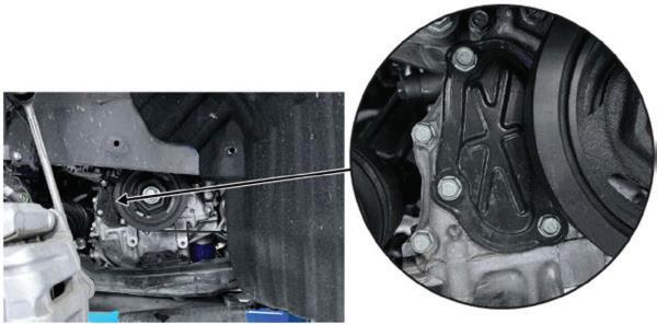
This bulletin applies to 2024–2025 Acura Integra Type S vehicles. An oil leak at the cam chain tensioner inspection cover may be found, caused by insufficient sealant adhesion. If a leak is verified (Acura recommends use of the engine oil leak detection kit P/N 07AAJ-5A2A100), re-seal the cover or replace the cover, as needed. The detection kit uses a compressed air charge (air bubbles confirm a leak). Use sealant P/N 08718-0004.
3. Plug the breather tube using a rubber plug.
4. Remove the engine oil dipstick.
5. Insert the appropriate size fitting into the dipstick hole.
6. Connect one end of the detection kit’s air pump hose to the small end of the fitting and insert the other end into the kit’s air pump.
7. Turn the air pump on.
8. Wait for two minutes, and then confirm the crankcase is holding air pressure by pulling the fitting out of the dipstick hole while listening for a pressure release.
9. Once pressure is confirmed, remove the right front wheel.
10. Remove the clips and pull down the underbody splash shield to access the tensioner inspection cover.
11. Spray the suspected leak area with soapy water.
12. Look for air bubbles to confirm a leak.
13. If a leak is confirmed, turn the pump off and remove the cam chain tensioner inspection cover. Remove the old sealant with a scouring pad (if re-using the cover). Apply a 2.5 mm bead of sealant to the cover. Reinstall the cover within four minutes of applying the sealant and torque bolts to 9 ft-lb. Reinstall the dipstick. Wait at least 30 minutes INFORMATION COURTESY OF MITCHELL 1
If no issues are found, explain to the customer that steering wheel heating is used for comfortable temperature control of the steering wheel rim. The system is working by design, and there’s
1. With the engine off and the engine cover removed, use plastic hose pinching pliers to pinch off the PCV tube.
2. Remove the intake tubing to gain access to the breather tube.
after installing the cover before adding oil to the engine. Don’t run the engine for at least three hours.
Photo Courtesy Acura
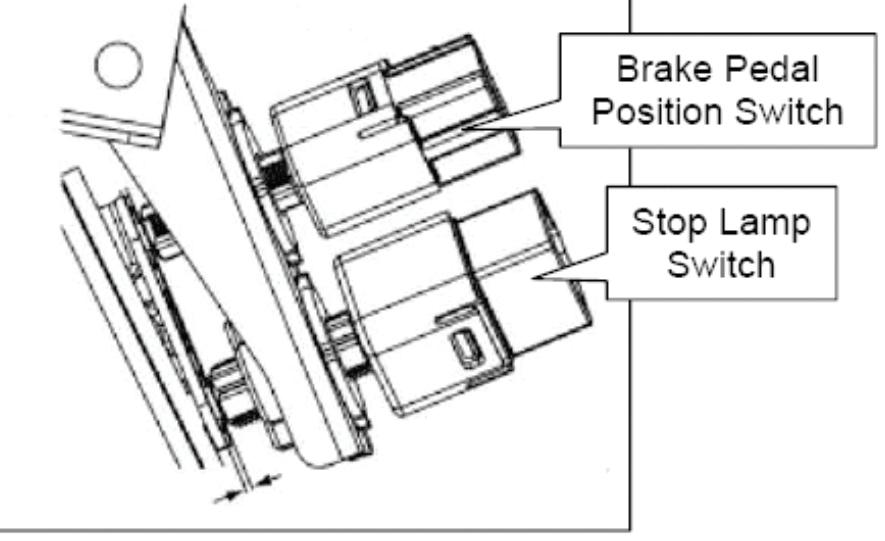
This bulletin applies to 2019–2022 Nissan Altima, 2022 Frontier, 2019–2022 Murano, 2022 Pathfinder, and 2019–2022 Titan/Titan XD vehicles. DTC C1142 (PRESS SEN CIRCUIT) and/ or C1116 (Stop Lamp SW) may be stored if the stop lamp switch and/or brake pedal position switch are out of adjustment. Before replacing any parts for these codes, confirm that the stop lamp switch and the brake pedal position switch are properly adjusted. Refer to the service manual for adjustment procedures.
Photo Courtesy Mitchell 1

This bulletin applies to 2022 Jaguar XF, XE, and I-PACE vehicles. JLR has had reports of no power steering assist at the start of a drive cycle. An advanced driver assistance system warning message appears on the instrument panel, and DTC U0400-81 is set on the driver assistance domain controller. The cause is a software error.
Don’t replace any parts before completing the following steps:
14. Run the network integrity test (NIT) vehicle application.
15. Run the power steering control module (PSCM) data collection module application.
16. Complete the 12V battery reset: disconnect and reconnect the 12V battery.
17. Confirm that the fault is resolved. If not, continue diagnosis using TOPIx support.
Photo Courtesy Jaguar
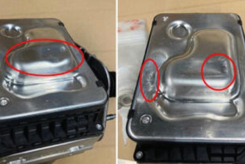
This bulletin applies to 2025 BMW HV vehicles. After programming from the I-Levels between 24-03-505 and lower and 24-03-540 to I-Level 24-11530 or higher, the message CCM-2525: “Brake system—drive at moderate speed” may be displayed. An imminent failure of the integrated braking system (IB) has been detected. Fault code 480B18 (DSC unit— internal position sensor linear actuator, electrical fault) may be logged. Replace the IB module for the fault code 480B18. Be sure to review the full replacement procedure before beginning any work on the IB. Don’t install any part that shows visual damage. Before disconnecting or removing any HV component, the HV system needs to be disabled and secured by means of the HV service disconnect switch and lockout by a properly trained HV technician.
Photo Courtesy BMW

This bulletin applies to 2024–2025 Mazda CX-90 PHEV and 2025 CX-70 PHEV vehicles built before March 1, 2025. Some vehicles may exhibit a check engine light on at engine startup, with DTC P0531:00 (refrigerant pressure sensor No. 1 system, function malfunction) stored in memory. This is caused by improper control logic of the PCM and the dash-electrical supply unit (Dash-ESU).
To eliminate the concern, the control logic has been modified. Reprogram the PCM and Dash-ESU with the Mazda Modular Diagnostic System (M-MDS), using Mazda Diagnostic and Repair Software (MDARS). Photo Courtesy Mazda

This bulletin applies to all 2008 and newer Nissan vehicles except LEAF and Titan XD with V8 diesel. If DTC P0456 (EVAP leak—very small leak) is stored, this code isn’t caused by a loose fuel fill cap. An EVAP leak has been detected where the vent control valve mounts to the canister. The vent control valve O-ring seal is determined to be the cause. Replace the vent control valve as an assembly. The O-ring is no longer available as a service part. Photo Courtesy Nissan

Some Mazda vehicles may exhibit a check engine light with DTC P20F8:00 (swirl control circuit range/performance problem). This includes 2024–2025 CX30, CX-5, CX-50, and Japan-built Mazda3, as well as 2023–2025 Mexico-built Mazda3 vehicles.
The DTC is caused by overheating of the swirl control valve (SCV) motor, which leads to duty limitation, causing poor opening angle response, resulting in a stuck condition. To eliminate the concern, the PCM control software has been modified. Reprogram the PCM with the Mazda modular diagnostic system (M-MDS). Photo Courtesy Mazda
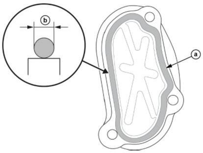
This bulletin applies to 2024–2025 Acura Integra Type S vehicles. An oil leak at the cam chain tensioner inspection cover may be found, caused by insufficient sealant adhesion. If a leak is verified (Acura recommends use of the engine oil leak detection kit P/N 07AAJ-5A2A100), re-seal the cover or replace the cover, as needed. The detection kit uses a compressed air charge (air bubbles confirm a leak). Use sealant P/N 08718-0004.
To verify a leak, with the engine off and engine cover removed, use plastic hose pinching pliers to pinch off the PCV tube. Remove the intake tubing to gain access to the breather tube. Plug the breather tube using a rubber plug. Remove the engine oil dipstick. Insert the appropriate size fitting into the dipstick hole. Connect one end of the detection kit’s air pump hose to the small end of the fitting and insert the other end into the kit’s air pump. Turn the air pump on. Wait for two minutes, then confirm that the crankcase is holding air pressure by pulling the fitting out of the dipstick hole and listening for a pressure release. Once pressure is confirmed, remove the right front wheel, remove the clips, and pull down the underbody splash shield to access the tensioner inspection cover. Spray the suspected leak area with soapy water and look for air bubbles to confirm a leak. If a leak is confirmed, remove the cam chain tensioner inspection cover and the old sealant. Apply a 2.5 mm bead of sealant to the cover, reinstall within 4 minutes, and torque bolts to 9 ft-lb. Wait at least 30 minutes before adding oil, and don’t run the engine for at least 3 hours. Photo Courtesy Acura

This bulletin applies to 2023–2024 Lincoln Corsair vehicles. Some vehicles may exhibit all of the following conditions:
• Inoperative BlueCruise and lane centering
• DTC U2018:51 stored in the CMR
• U0565:86 stored in the IPMA
• U3000:49 isn’t stored in the CMR
This may be due to the software in the CMR. Reprogram the CMR module using the latest software level of the FDRS.
Photo Courtesy Lincoln

This bulletin applies to 2023–2025 Jeep Commander, Compass, and Renegade vehicles. The MIL may be on with DTC C170C-00 (event PBC factory mode), C1436-86 (electric parking brake system fail), and/or C10D0 (electronic park brake system failure). The vehicle may not accelerate properly, and the ABS warning light may be on. The cause is the ABS module. Replace the ABS module.
Photo Courtesy Jeep

FORD MAVERICK HEADLAMP PROBLEM
Some 2024 Ford Maverick vehicles equipped with low-series headlamps and built November 14, 2023, through January 31, 2024, may exhibit one or both headlamp high beams inoperative, with DTC B14E5:01 and/or B14E7:01 stored in the BCM. This may be due to the headlamp assembly.
1. Apply the parking brake. Start the engine and place the gear selector in neutral.
2. With the headlamp switch in the “Auto” position, place a bright lamp over the ambient light sensor that’s located at the top/center of the instrument panel near the windshield, to simulate sunlight. Make sure that the low beams aren’t illuminated and the DRL is on.
3. Pull the turn signal arm toward the driver several times to activate/ flash the headlamp high beams.
4. If one or both high beams are inoperative, perform a self-test of the BCM. If only DTC B14E5:01 and/or B14E7:01 are present, replace the affected headlamp assembly.
• RH headlamp assembly: NZ6Z13008-A
• LH headlamp assembly: NZ6Z13008-C
Photo Courtesy Ford
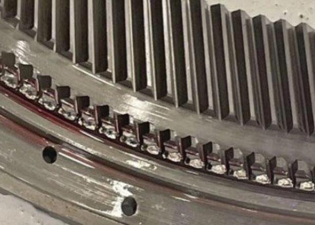
CHEVROLET NO REVERSE GEAR?
This bulletin applies to 2021–2025 Chevy Silverado, Suburban, and Tahoe vehicles equipped with an automatic transmission. The vehicle may experience no reverse engagement and DTC P2714 stored. The cause: the input internal gear may have separated from the direct overdrive sun gear shaft due to the input internal gear retainer ring being dislodged. Perform an internal transmission inspection to determine if the R2S3 retaining ring

is dislodged. If the ring is dislodged, replace the retainer ring with P/N 4356498. Photo Courtesy Mitchell 1
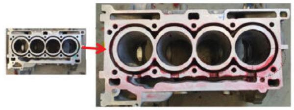
This bulletin applies to 2021–2024 Jeep Wrangler, Compass, and Grand Cherokee vehicles equipped with a 2.0L I4 DOHC turbo or turbo PHEV engine. A rough engine idle during cold starts and low coolant level in the coolant recovery bottle may be observed. The cause may be due to cylinder block porosity.
1. Cold start the engine to verify that the engine runs rough initially and then runs normally after 30 seconds of run time.
2. If so, identify the cylinder(s) having a misfire condition.
3. Set the affected cylinder piston to bottom dead center.
4. Using a cooling system pressure tester, pressurize the cooling system up to 21 psi with the engine at normal operating temperature for 12 minutes.
5. Observe pressure decay on the pressure tester gauge.
6. Using a borescope, inspect for any trace of coolant in the affected cylinder(s) while the system is pressurized. Make sure to inspect the entire bore perimeter.
7. Also check for block cracks by using a dye liquid penetrant on the block deck area.
8. If coolant is detected, and/or if cracks are found on the deck, replace the long block assembly.
Photo Courtesy Jeep