MaxiSYS





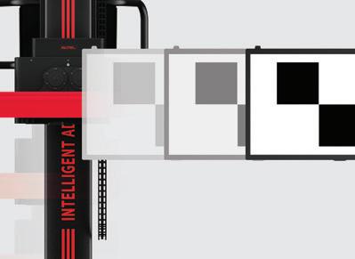










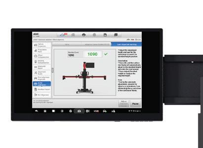











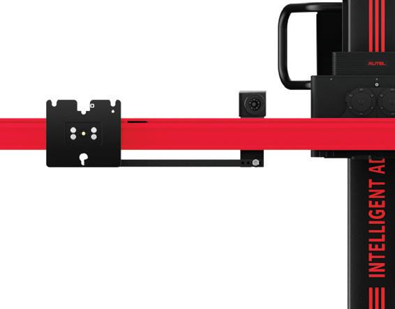

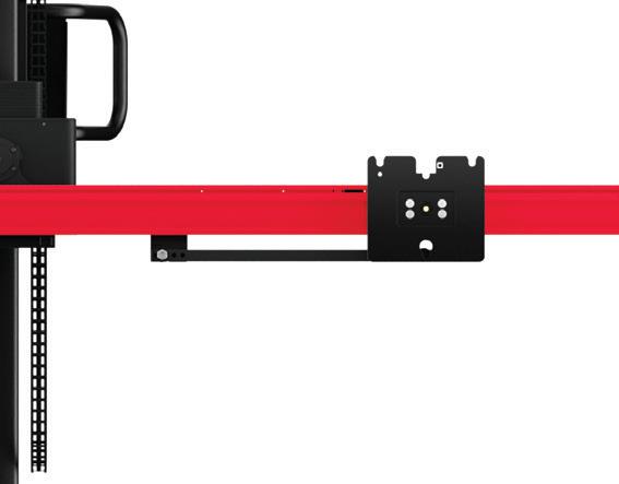




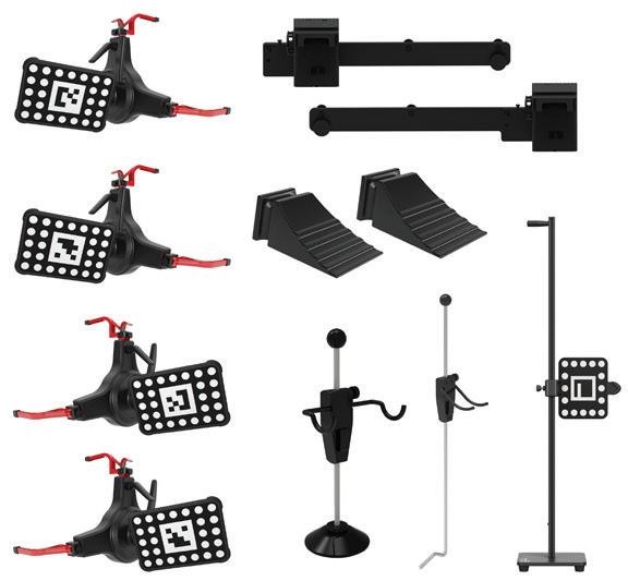
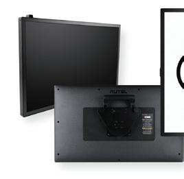
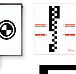

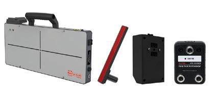
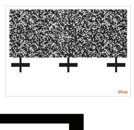




60+PIECESINCLUDED








GET1EXTRAYEARFREEOFADASSOFTWAREUPDATESWITHPURCHASE












60+PIECESINCLUDED
GET1EXTRAYEARFREEOFADASSOFTWAREUPDATESWITHPURCHASE
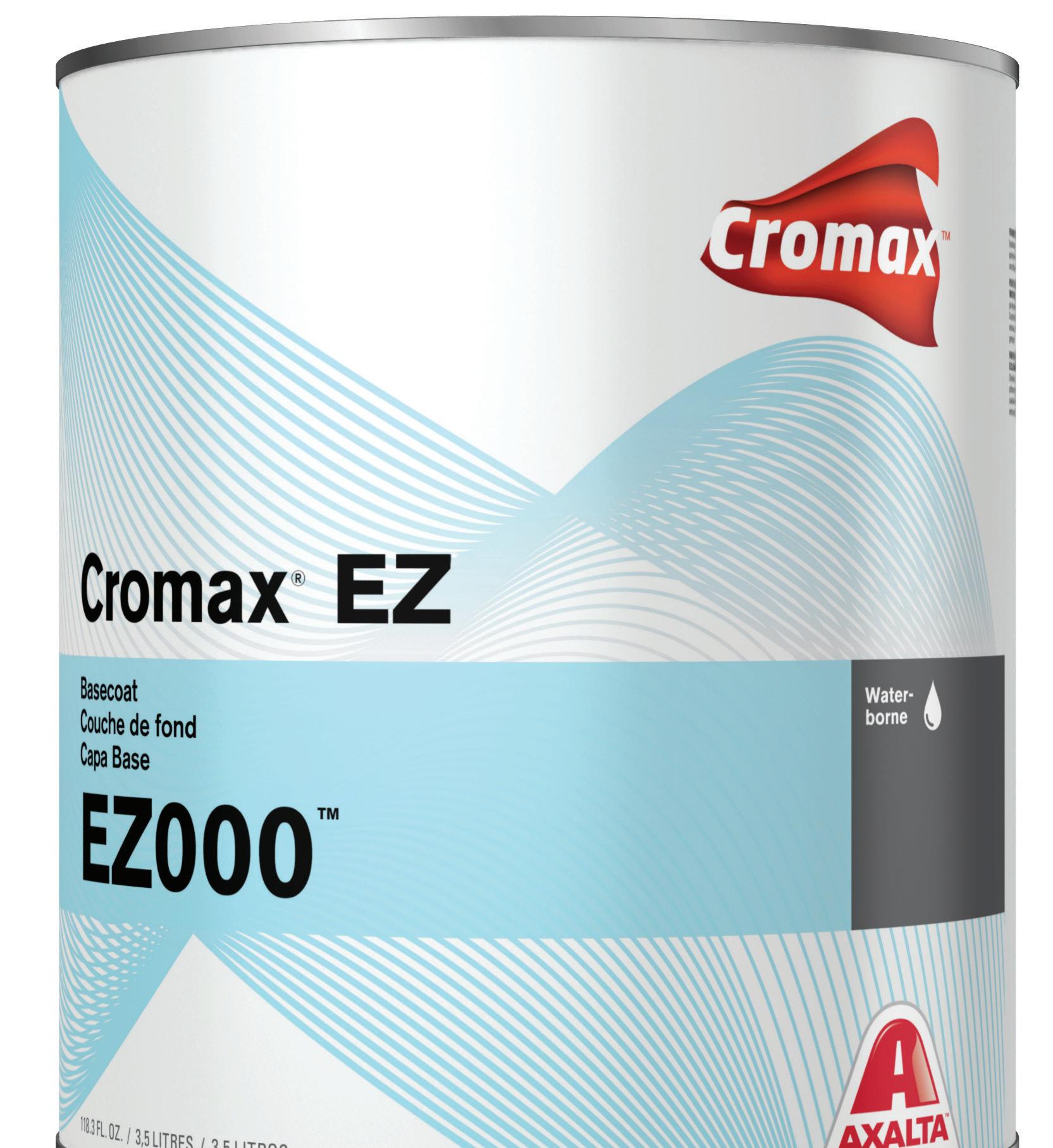
With a waterborne basecoat that’s easy to mix, match and apply and that uses the same coat flash application you’ve already perfected, Cromax® EZ makes an exceptional finish feel effortless. Discover how easy an outstanding finish can be.
axalta.us/ez
Effective diagnostics require discipline, evidence-based decision-making, and a process that adapts to the increasing complexity of vehicle systems, especially in ADAS calibration and repair.
BY PAUL BOSTEL
Meticulous preparation, correct product use, and adherence to repair procedures will help ensure successful outcomes.
BY SHAWN COLLINS
Plastic welding strips and textured coatings enable technicians to efficiently restore damaged parts, maintaining original textures and minimizing environmental impact.
BY ALEJANDRA GALLEGO
Learn the steps needed for success with these complex, vibrant colors.
BY JAY SICHT
Digital tools, proper planning, and communication can help achieve accurate color matches, reducing rework and maximizing shop efficiency when working with complex special-effect finishes.
BY STEVEN MATTHEWS
Learn essential techniques, including surface preparation, spray techniques, and flash times, to achieve invisible repairs and consistent color matches.
BY MICHAEL NELSON





NEW I-CAR PROGRAMS OPEN CAREER PATHWAYS FOR ILLINOIS STUDENTS
DEG SHARES ESTIMATING TIP FOR CCC ON BLENDING TWO-TONES
YOU’RE USING THE WRONG ELECTRODE WIRE BY
JASON BARTANEN
Endeavor Business Media, LLC
30 Burton Hills Blvd, Ste. 185, Nashville, TN 37215 Phone: 800-547-7377
EDITORIAL STAFF
CHRIS JONES
GROUP EDITORIAL DIRECTOR christopherj@endeavorb2b.com
JAY SICHT
EDITOR-IN-CHIEF jsicht@endeavorb2b.com
PETER SPOTTS
ASSOCIATE EDITOR pspotts@endeavorb2b.com
JENNIFER DAKAS ART DIRECTOR
CONTRIBUTORS
JASON BARTANEN, PAUL BOSTEL, SHAWN COLLINS, ALEJANDRA GALLEGO, TROY KNOPIK, STEVEN MATTHEWS, MICHAEL NELSON
ENDEAVOR BUSINESS MEDIA
CEO CHRIS FERRELL
SALES STAFF
ANDREW JOHNSON PUBLISHER ajohnson@endeavorb2b.com
MATTIE GORMAN-GREUEL SALES DIRECTOR mgorman@endeavorb2b.com
CORTNI JONES DIRECTOR OF BUSINESS DEVELOPMENT cjones@endeavorb2b.com
Account Executives:
DIANE JOHNSTON djohnston@endeavorb2b.com
MARIANNE DYAL mdyal@endeavorb2b.com
CHAD HJELLMING chjellming@endeavorb2b.com
LISA MEND lmend@endeavorb2b.com



AUSTIN MILLER austinm@endeavorb2b.com
COO — PATRICK RAINS
CDO JACQUIE NIEMIEC
CALO TRACY KANE
KYLE SHAW kshaw@endeavorb2b.com
CMO AMANDA LANDSAW




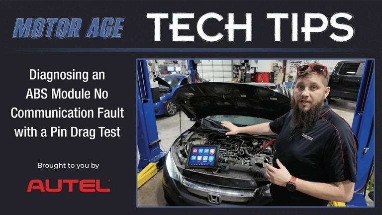
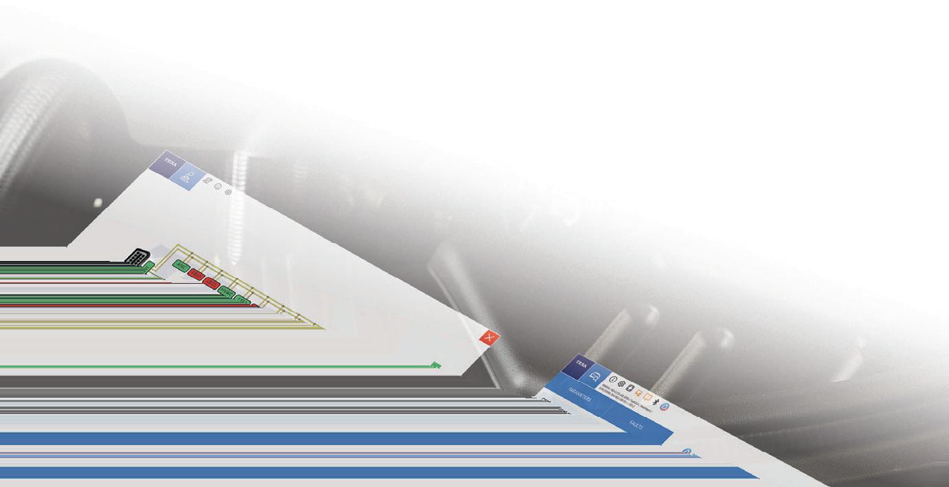
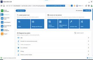
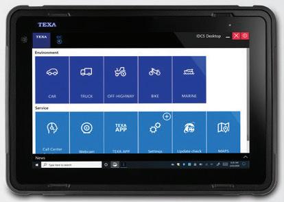
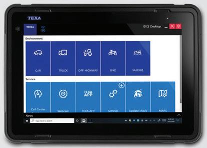
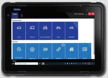
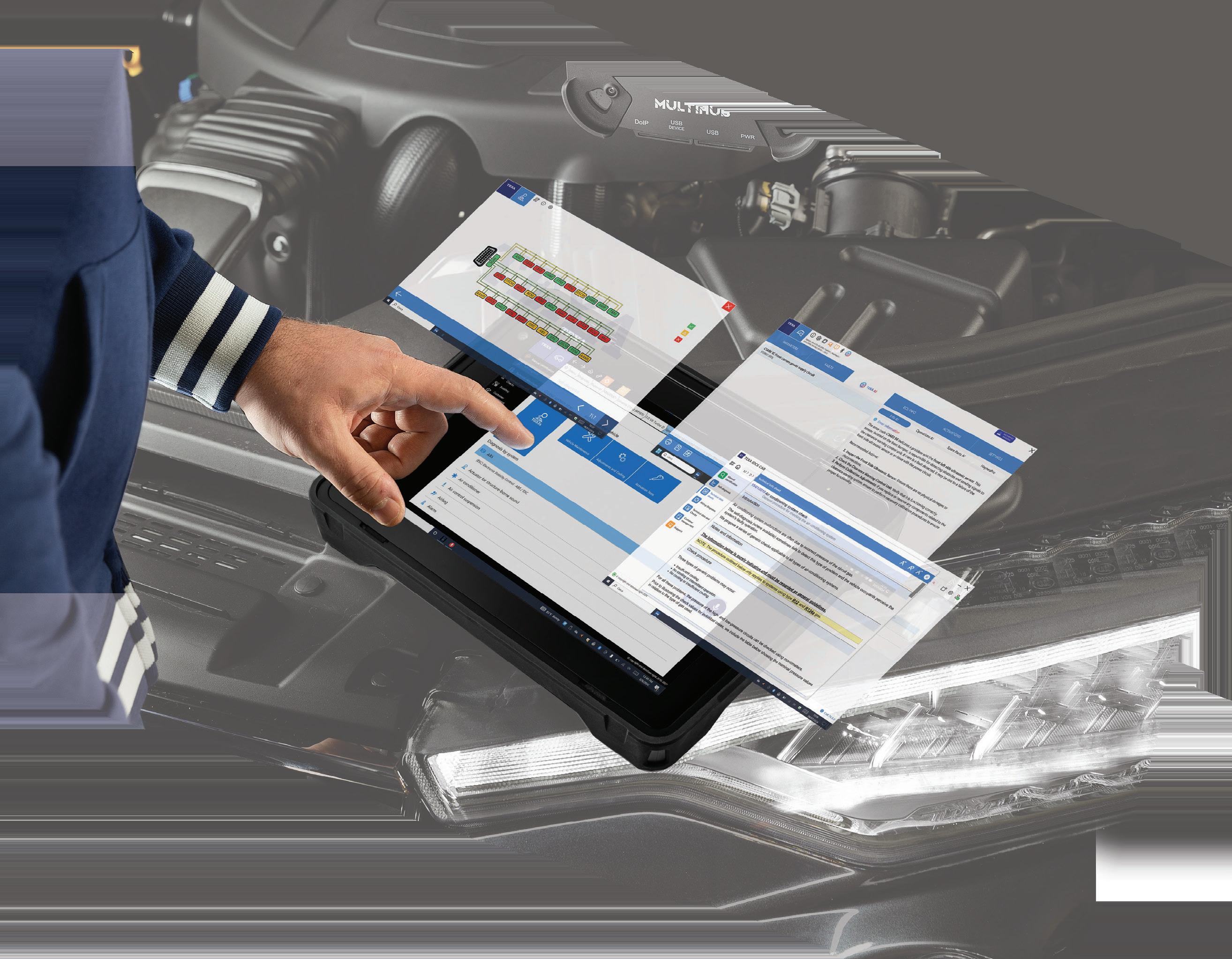
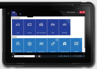
In this hands-on diagnostic walkthrough, Keith Perkins shares with the collision repair audience knowledge he typically provides Motor Age readers for ABS module diagnostics of a 2017 Honda Civic.
Using the Autel MaxiSYS Ultra S2 diagnostics platform, Perkins showcases how advanced scan tools can streamline the entire repair process, from initial vehicle scan and topology mapping to pinpoint testing and final validatiown.
Watch the full video to follow the complete diagnostic process and see how a methodical approach leads to a confirmed fi x.
HTTPS://AUTEL.US/PRODUCT/ MAXISYS-ULTRA-S2/.
EVP TRANSPORTATION GROUP CHRIS MESSER
VP OF CONTENT STRATEGY, TRANSPORTATION GROUP JOSH FISHER
BUSINESS STAFF
MICHAEL WILLINS BUSINESS DEVELOPMENT DIRECTOR, MOTOR AGE TRAINING
MARIAH STRAUB
PRODUCTION MANAGER
JENNIFER GEORGE AD SERVICES MANAGER
TRACY SKALLMAN AUDIENCE DEVELOPMENT MANAGER
JILLENE WILLIAMS SALES COORDINATOR
SEAN THORNTON sthornton@endeavorb2b.com
JAMES HWANG Inside Sales & Brand Manager, ASE Study Guides jhwang@endeavorb2b.com
REPRINT SERVICES reprints@endeavorb2b.com.
CUSTOMER SERVICE Subscription Customer Service 877-382-9187; 847-559-7598
ABRN@omeda.com PO Box 3257 Northbrook IL 60065-3257
ABRN is published 4 times yearly (March, June, October, December) by Endeavor Business Media, LLC. 30 Burton Hills Blvd, Ste. 185, Nashville, TN 37215. Customer service can be reached toll-free at 877-382-9187 or at ABRN@omeda.com for magazine subscription assistance or questions.
Printed in the USA. Copyright 2026 Endeavor Business Media, LLC. All rights reserved. No part of this publication may be reproduced or transmitted in any form or by any means, electronic or mechanical, including photocopies, recordings, or any information storage or retrieval system without permission from the publisher. Endeavor Business Media, LLC does not assume and hereby disclaims any liability to any person or company for any loss or damage caused by errors or omissions in the material herein, regardless of whether such errors result from negligence, accident, or any other cause whatsoever. The views and opinions in the articles herein are not to be taken as official expressions of the publishers, unless so stated. The publishers do not warrant either expressly or by implication, the factual accuracy of the articles herein, nor do they so warrant any views or opinions by the authors of said articles.
Endeavor Business Media provides certain customer contact data (such as customers’ names, addresses, phone numbers, and e-mail addresses) to third parties who wish to promote relevant products, services, and other opportunities that may be of interest to you. If you do not want Endeavor Business Media to make your contact information available to third parties for marketing purposes, simply call toll-free 877-382-9187 or email ABRN@omeda.com and a customer service representative will assist you in removing your name from Endeavor Business Media’s lists. ABRN does not verify any claims or other information appearing in any of the advertisements contained in the publication, and cannot take responsibility for any losses or other damages incurred by readers in reliance of such content. ABRN welcomes unsolicited articles manuscripts, photographs, illustrations and other materials but cannot be held responsible for their safekeeping or return.
With more Illinois students seeking a ordable, technology-forward career paths, I-CAR has launched new statewide programs to introduce high school learners to the engineering, science, and advanced technologies behind modern automotive repair. e initiatives are funded through grants from the Illinois Department of Commerce and Economic Opportunity (DCEO), according to a news release.
Illinois is serving as the launch state for I-CAR’s new high school pre-apprenticeship program, which gives students early, hands-on exposure to diagnostics, electronics, materials science, and repair procedures used in today’s clean-energy and advanced-technology vehicles. A pre-apprenticeship provides foundational skills that prepare students to qualify for a paid, on-the-job apprenticeship leading to an industry credential. This Illinois pilot will serve as the foundation for a planned national rollout in the 2026–27 school year.
Beginning in the 2026–27 school year, students at participating Illinois high schools will be able to earn I-CAR’s Electric and Alternative Energy Vehicle Badge through the I-CAR Academy entry-level technician learning platform. Eligible students who complete the badge will receive professional tool kits, addressing one of the most common barriers to entry into skilled trades and enabling a smoother transition into post-graduation training or apprenticeship programs on I-CAR’s platform.
To strengthen the employer side of the pipeline, I-CAR is also offering incentive packages to Illinois repair centers to
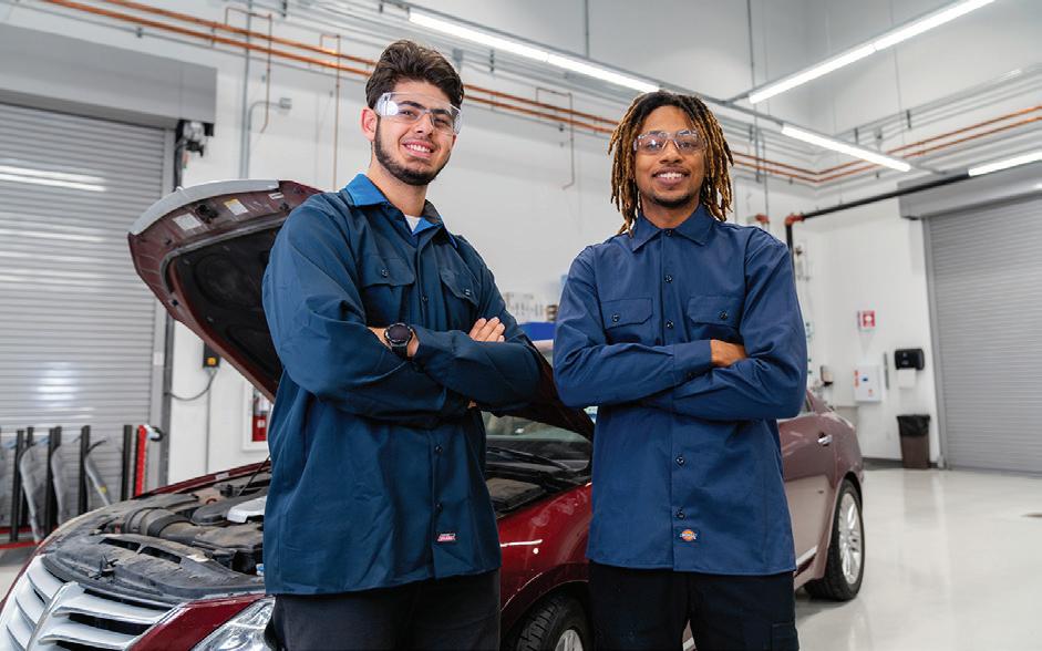
recruit, train, and retain entry-level employees through its U.S. Department of Labor-backed Registered Apprenticeship Program (RAP). Launched in 2025, the RAP established a consistent, nationally recognized pathway for automotive apprentices that aligns collision repair with other highly competitive skilled trades.
“Automotive collision repair has become a high-tech, STEM-based profession,” said Dara Goroff, I-CAR vice president of product management. “Students are working with the same technologies found in engineering labs and advanced manufacturing, creating affordable, sustainable career opportunities tied to real jobs.”
The initiatives aim to build a stronger talent pipeline, reduce student training costs, and give Illinois employers access to more career-ready entry-level technicians.
Society of Collision Repair Specialists shares a tip from DEG Inquiry 40990 (degweb.org/inquiries/40990/), which provides MOTOR feedback regarding blending operations on two-tone re nish panels.
“The Blend calculation is determined from the full refinish time of the component based on the MOTOR GTE Pages. Additional refinish stages are
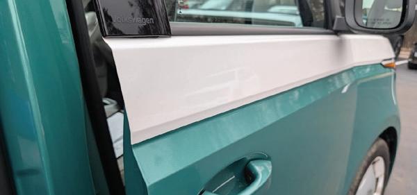
not considered. If additional refinish time is needed to blend a two- tone panel, then a manual estimate change would be required.”
The estimating databases are intended for use as a guide only. The auto body professional performing the repair is in a position to thoroughly inspect, diagnose, and identify the methodology and cost of the vehicle damage repair. View this tip and others on the DEG website at degweb.org/estimating-tips. For more information about SCRS or to become a member, visit scrs.com.
The evolution of vehicle materials necessitates a shift in welding habits, particularly in choosing electrode wire diameters.
BY JASON BARTANEN
at title is intentionally painted with a broad brush, and to be fair, many technicians are using the correct electrode wire. In other cases, the wire being used may not be technically “wrong,” but it is not be the best choice from a usability and weld-quality standpoint on the thin, lightweight steels we’re welding today.
This month’s topic also is not based on one specific inquiry. Instead, it comes from patterns we’ve seen through questions submitted over the last several years and another Collision ProAssist service, our OEM welding training and validation program, where first-hand observations played a key role in prompting this article.
Most of the industry is still using ER70S-6 solid wire for automotive gas metal arc welding, and that remains the most common recommendation, with an occasional OEM specifying (or allowing) ER70S-3 instead. We’re
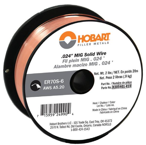
good there. Technicians generally follow those wire-type directives when they are provided. But what is often missing is any clear instruction on electrode wire diameter. In fact, most OEM procedures that call for steel GMAW and name the wire classification, say little or nothing about the size of the electrode wire. This is a critical gap, given the thickness of most of today’s steel panels that allow GMAW welding.
A common issue I continue to see is technicians defaulting to 0.030” (0.8 mm) electrode wire when 0.023”, 0.024”, or 0.025” (0.6 mm) wire is usually the better option.
That is especially true on the thinner steels that now make up much of today’s exterior body structures, where controlling heat input matters just as much as achieving fusion.
Many of us learned to weld years ago on thicker, milder steel. Back then, the mindset was simple: burn the weld in, get more penetration, and assume more heat meant improved fusion and a better weld. On older, thicker, mild steel materials, that worked. On today’s thinner, higher strength steels, it can create problems.
Modern vehicles use much thinner
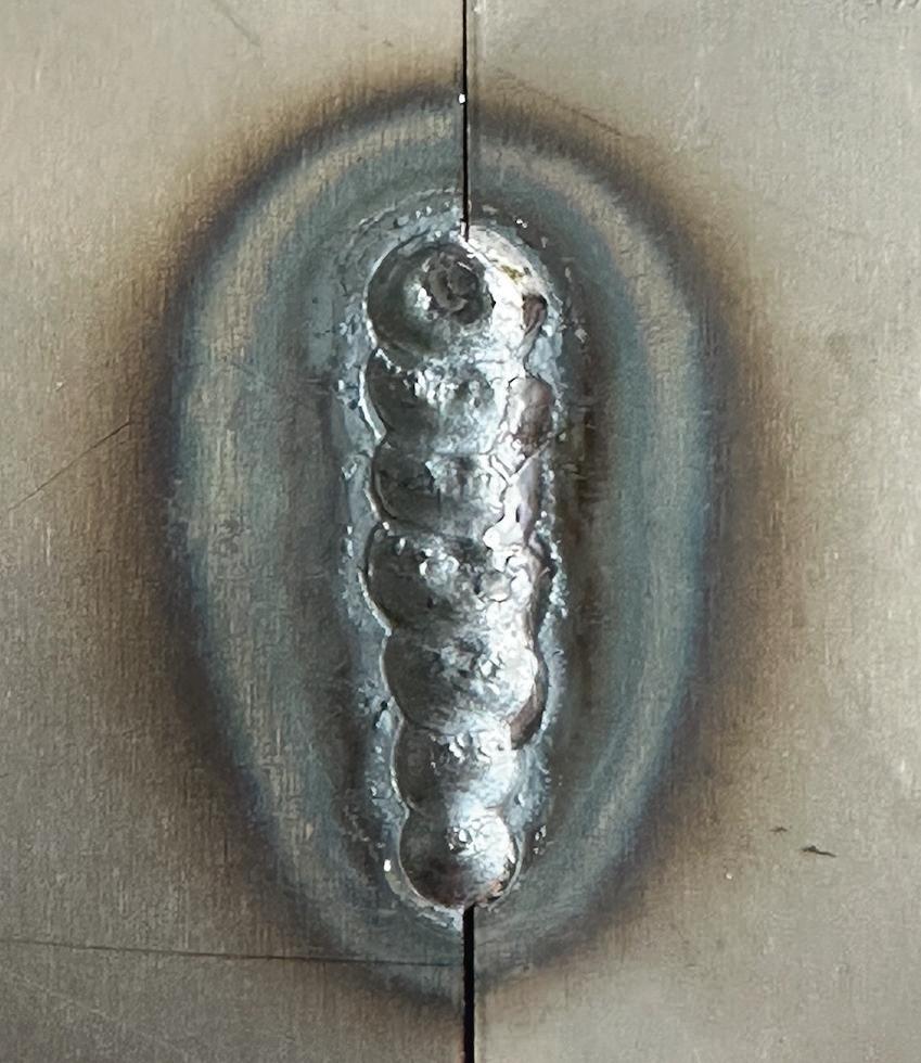
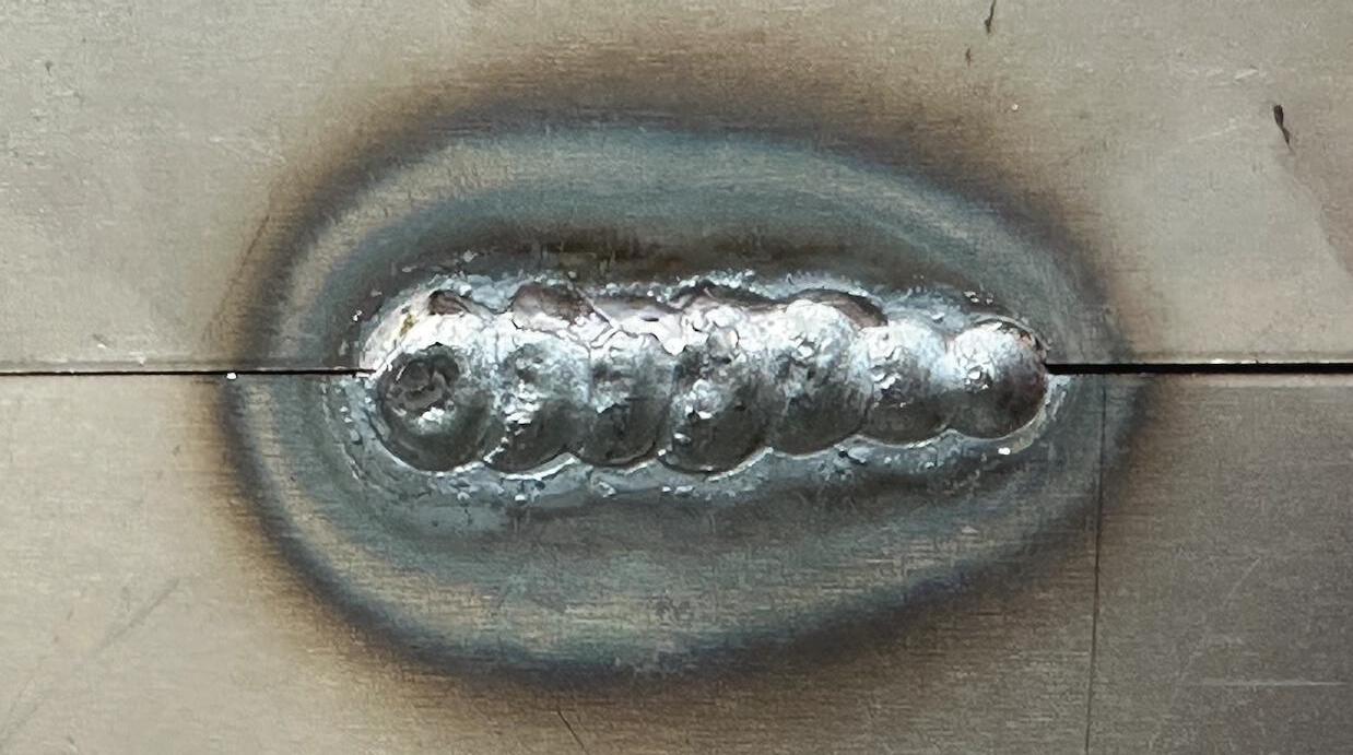
THE BACKSIDE (yes, this is the backside) of this weld made with 0.030” has excessive penetration and a sizable heat-affected zone.
material, and the extra heat required to run 0.030” electrode wire can do more harm than good. Too much heat can cause excessive penetration (and potentially burnthrough), enlarge the heat-affected zone (HAZ), increase the likelihood of panel distortion, and make it harder to make a good weld.
That is where electrode wire diameter becomes more than just a preference issue. Smaller diameter wire generally gives the technician a more usable setup for thin automotive steel. It can help control heat, while achieving appropriate penetration.
One electrode wire maker notes that both 0.024” and 0.030” solid wire could be used to weld materials as thin as 22 gauge (0.78 mm) and as thick as 18 gauge (1.27 mm).
When we compare this chart with an OEM material thicknesses illustra-
tion, 0.030” wouldn’t be appropriate for any of the mild steel panels on this vehicle; 0.024” electrode wire would be the correct option.
That matters because when we compare those recommendations to the material thicknesses shown for late-model vehicles, including the GM example, much of what technicians are welding falls squarely in that lighter range. When you start looking at material thicknesses in that 0.6 – 0.7 mm range, it becomes clear that we are often dealing with material that does not need the added heat burden that commonly comes with 0.030” wire.
There is also a practical side to this conversation. Frankly, it’s easier to weld
thinner material with 0.024” electrode wire. I find myself making a lot fewer adjustments (at the machine and in technique), and producing better welds, when I’m welding thinner material with 0.024” vs. 0.030”.
An important note: when you decide to move to the smaller electrode wire, the rest of the system must match as well. That means using the proper drive rolls, the correct contact tips, and the right liner for the smaller wire size.
None of this is meant to suggest that 0.030” wire never has a place; use it when the material thickness warrants it or when the OEM calls for it. The point is that too many technicians appear to be using it as the default, even in situa-
tions where a smaller wire would offer better usability and better weld quality. For much of today’s automotive steel, 0.023” to 0.025” electrode wire should be your default.
As vehicle materials continue to evolve, our welding habits must evolve with them. The procedures, the settings, the material thickness, and the consumables all need to work together. If we are still applying thick-steel logic to thin, modern automotive steels, we may be creating excessive HAZ, unnecessary distortion, and lower quality welds.
The takeaway is simple: if you’re using 0.030” electrode wire for thin mild steel panels, give 0.024” electrode wire a try; I think you’ll find it makes a noticeable difference.

BARTANEN is the founder and chief technician advocate of Collision ProAssist, where he guides technicians through technical support and tailored education. He has been in the collision repair industry for nearly 30 years, including more than 23 years serving in various roles for I-CAR, the Inter-Industry Conference on Auto Collision Repair. He was most recently the director of industry relations at Collision Hub for nearly six years
Automated
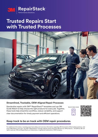
In collision repair, doing a job well extends before and after the actual work. And planning that work well—which includes tracking the use of consumable supplies, has a direct impact on pro tability. Knowing what adhesives, sealers and abrasives a job calls for keeps waste to a minimum, and accurate invoicing helps a shop recover the cost of what it uses. Later, performance analytics that track the whole shop’s work can help boost e ciency throughout the process.
says that compared to the open-shelf system his shop used to use, RepairStack has helped invoice and recoup over three times as much as before for materials like seam sealers, panel bonders and abrasives. Before this approach, a shop might buy supplies based on price or availability without reference to OEM-approved specs. Techs might take them from the shelves a box at a time, without tracking what they used on each job. Or they might start a job only to find the shop had run
One important factor is to ensure as many inputs as possible are tracked for billing and accepted for payment by the customer’s insurance. Knowing and applying OEM recommendations is a big part of meeting that challenge.
Consider the differences: Are the right supplies available when techs need them? Do they know ahead of time if they’re using a brand or specification that insurance will approve? Does the shop need to accept its use of consumables as a cost— or does it have the data to bill for every pad, tube and roll?
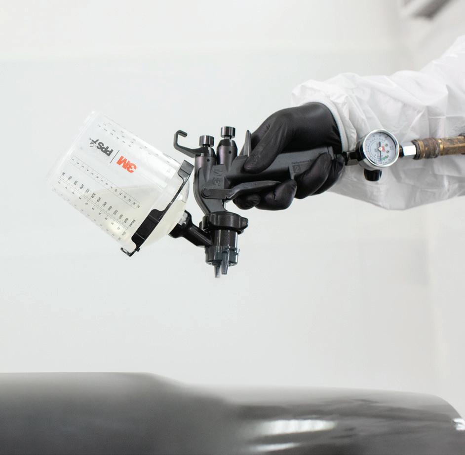
All of these considerations can help shops capture and retain value. They also represent extra work. One system that can help bridge that gap, by streamlining that effort and amplifying the benefits, is 3M™ RepairStack™ Performance Solutions.
Joe Hershey, Body Shop Manager at Bill Brown Ford in Livonia, Michigan,
out of an item they needed. When it came time to assemble an invoice, there wasn’t enough information to include the consumables for reimbursement. Shops knew they needed to exert some control, but the technology wasn’t there—some collision centers actually experimented with having techs “buy” supplies from internal vending machines.
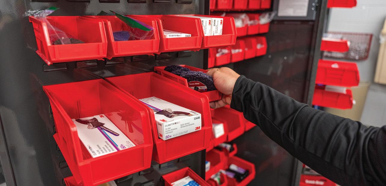
Now, systems like RepairStack™ help automate reordering based on actual use and OEM specs. Technicians have handheld scanners to open electronically controlled cabinets and register the products they use, creating an instant record of what’s used for each job. With this information, the shop can generate a real-time
record of materials used to include on each job’s invoice. That allows the shop to document the use of approved products and recoup the cost from insurers. Over time, RepairStack™ also compiles information that adds up to actionable business insights for greater efficiency.
The key benefits of this approach include:
• More reliable application of OEMapproved materials, which promotes job quality and eases insurance reimbursement
• Reduction of waste and overuse by dispensing needed products only in the needed amounts
• Automated inclusion of consumable material costs in job invoices, which transforms a cost of doing business into a revenue line
Like many experienced professionals, Hershey says his shop used to stock consumable products on open shelves without tracking. But no longer. “Materials such as abrasives that we would normally have issued by the box are now used individually,” Hershey says. Not only is that use metered and tracked, he adds, but there’s a record of which technician or painter used it, when, and on which job. Knowing that also helps make those team members more mindful of their own use of materials.
Shops that use the RepairStack™ system don’t have to stock their cabinets exclusively with 3M products. In addition, they have the option of expanding the system’s use into training, inventory management, and integration with the shop’s other information systems.
“I can tell you for a fact we’re recouping for materials we would once have written off as a cost of doing business,” Hershey says. “It’s the best system out there.”




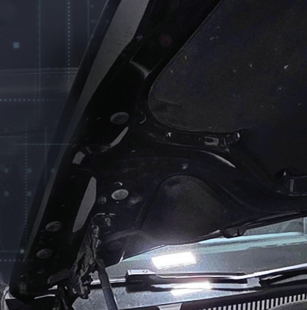
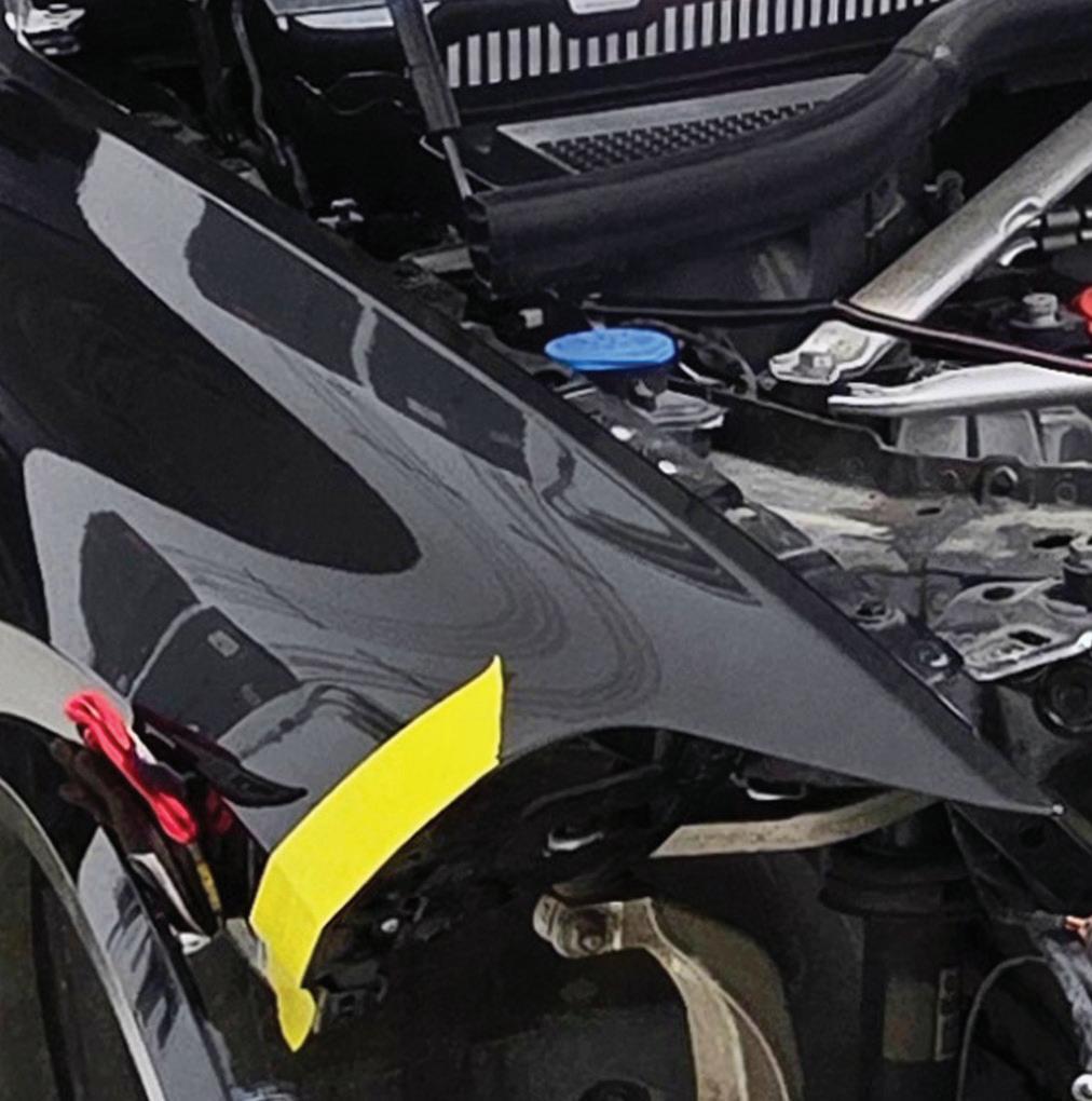
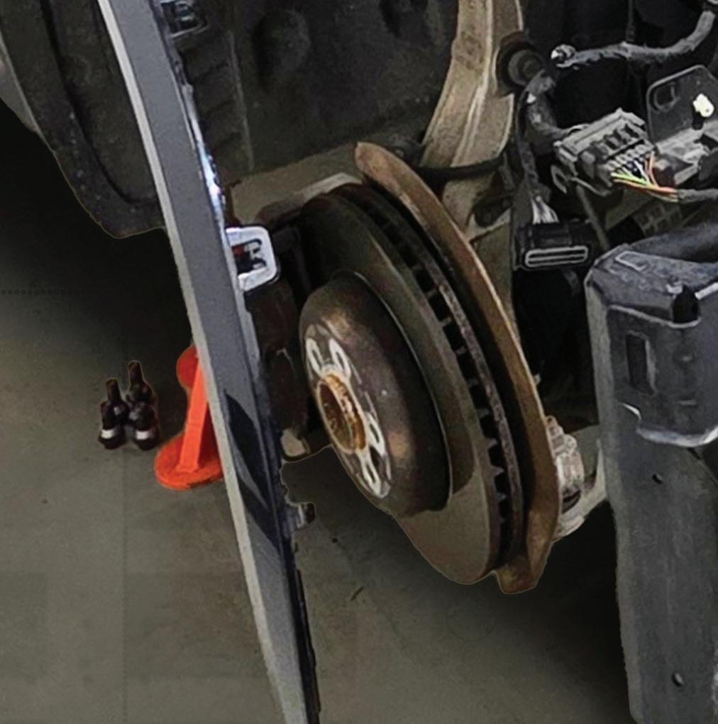
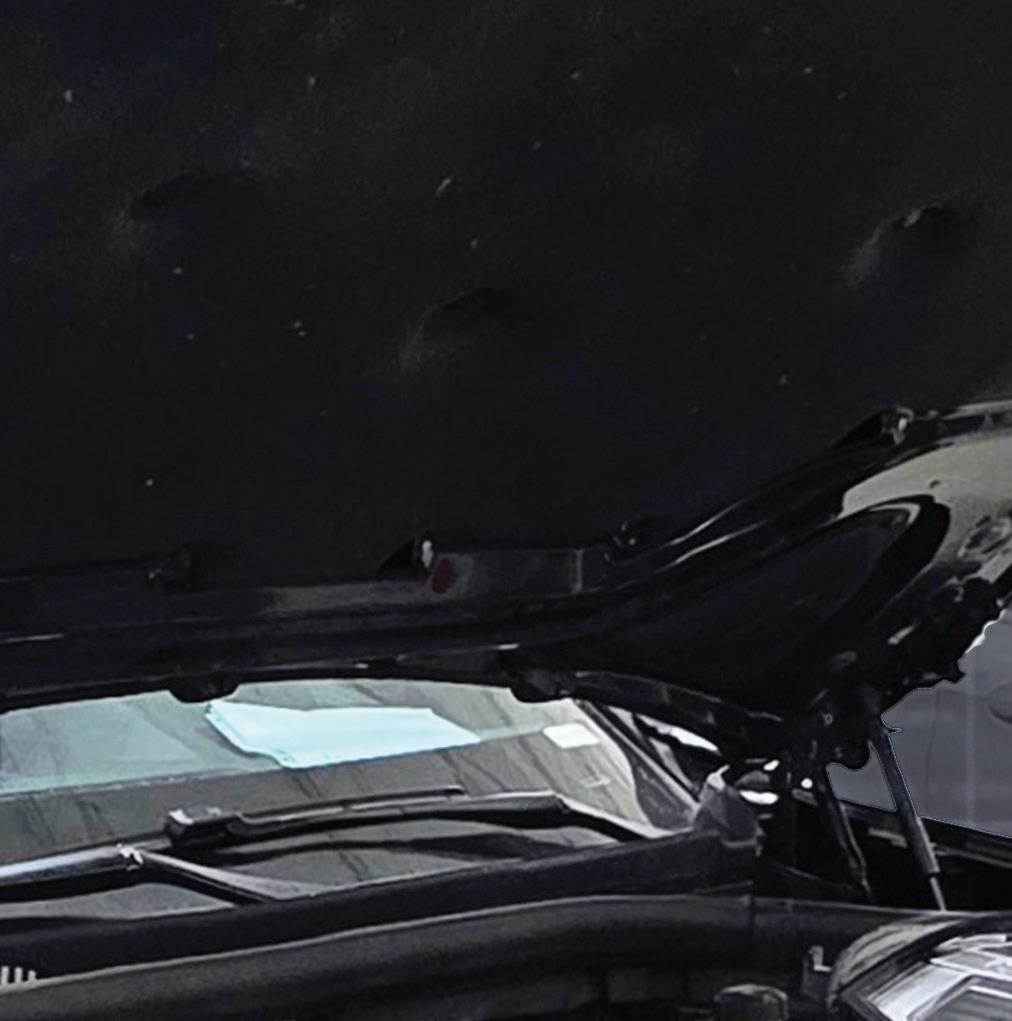
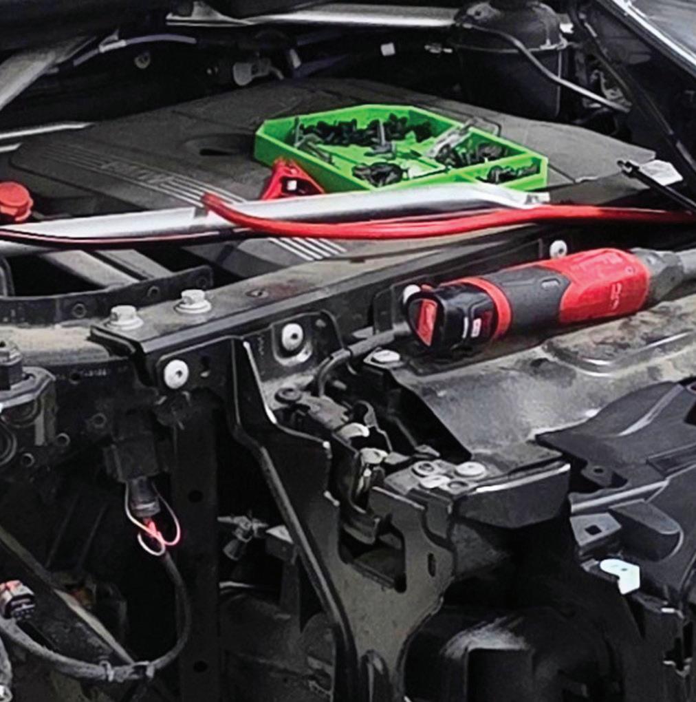
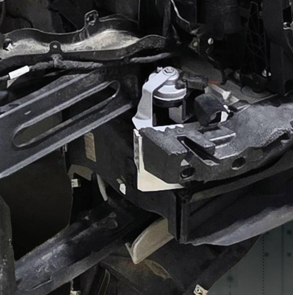
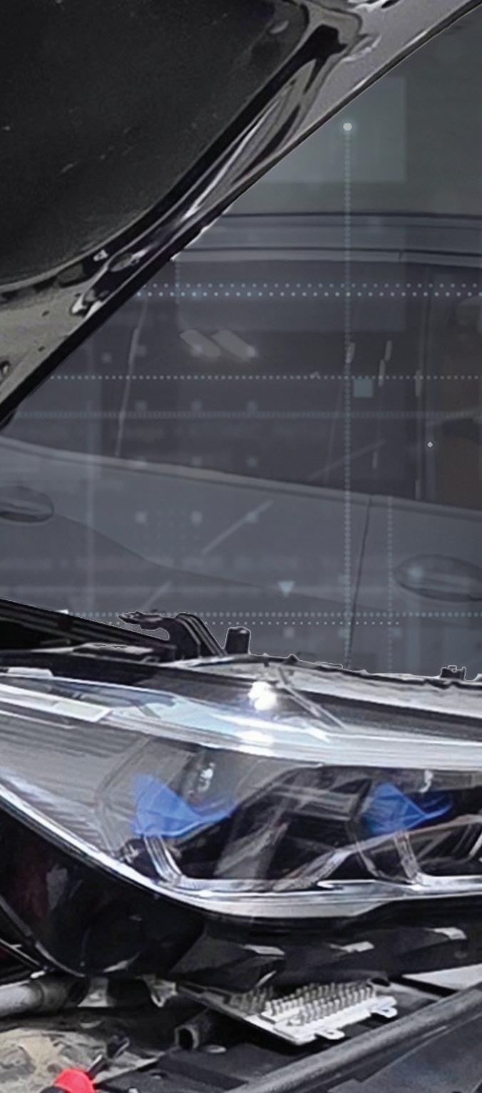
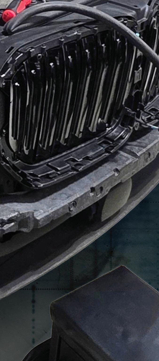

IF THE SPACE IS AVAILABLE , dedicated diagnostic stalls can be helpful in minimizing shop workflow disruptions where faster, higher volume work occurs.
PHOTOTS BY PAUL













EFFECTIVE DIAGNOSTICS REQUIRE DISCIPLINE, EVIDENCE-BASED DECISION-MAKING, AND A PROCESS THAT ADAPTS TO THE INCREASING COMPLEXITY OF VEHICLE




BY PAUL BOSTEL

hen it comes to diagnostics, my goal is simple: take the path most likely to repair the vehicle correctly the rst time. That sounds obvious, but it is where a lot of technicians still get sideways. Too many people are looking for a silver bullet. They want the one common fix, the one bad module, the one known issue that gets the vehicle out the door fast. Sometimes that works. More often it burns time, parts, and confidence. That problem gets worse as vehicle systems get more complex. Advanced driver assistance systems are one of the clearest examples of why diagnostic strategy matters.
ADAS calibrations themselves usually are not the hard part. The hard part is what happens when the calibration does not go through, the system does not behave like service information says it should, or the fault path is not obvious. This is where the gap shows between a diagnostician and a parts changer.
A diagnostician wants to know what the problem is, how the system is supposed to operate, what inputs it needs, what outputs it should produce, and what tests can confirm or deny a working theory. If the first round of tests does not produce anything conclusive, the diagnostician adjusts the hypothesis and keeps working.
A parts changer does something different. They go looking for the most likely answer before they fully

understand the problem. They jump on forums, search groups, or pull up a product that shows top fixes. They want someone else to hand them the answer. That is not diagnostic strategy. That is outsourced guesswork.
What made ADAS different was not just the sensors or targets. It was the number of ways a system could fail and still not give the technician a clean path to the answer.
A lot of technicians grew up with the idea that if you had a diagnostic trouble code and service information, you could work the problem from there. ADAS showed quickly that was not always true. You could have failure states with little to no useful DTC direction. You could have service information that only gave generic checks and sent the technician in circles. You could confirm that a module was mounted correctly and still have the problem be firmware, coding, version mismatch, or even whether the factory tool completed programming correctly.
As complexity has gone up, there are more ways for systems to fail. If a technician attacks a modern problem with old habits and assumes the path is linear, the odds of getting to the right answer go down.


One of the biggest mistakes technicians can make is treating the DTC as the problem. A DTC must be associated with some failure or error state in the vehicle, but that does not mean the system always failed in the exact way the flow chart assumes. Sometimes a system fails in a way that mimics a certain DTC path. The code is real. The symptom is real.
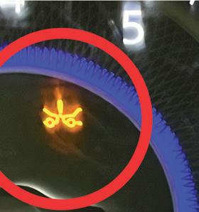
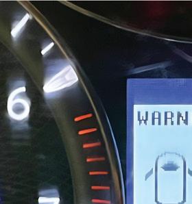
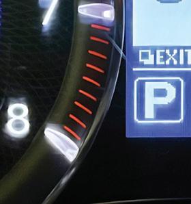

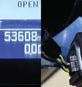


But the service information tied to that code may not be correct for the actual problem sitting in front of the technician.
That is where technicians get trapped. They trust the code too much. They skip checking TSBs and recalls. They do not verify firmware level. They jump to the bottom of the flow chart because they think they already know the answer. Or they replace a control
module too early without ruling out everything around it first.
When I start to suspect a module like a PCM, TCM, or BCM, I proceed with caution. Those modules are built to do a job at a high duty cycle. That does not mean they never fail. It means I want to be sure I have ruled out every other reasonable cause before I condemn one.
Technicians use judgment heuristics every day. There is nothing wrong with pattern recognition; a technician’s experience matters. The problem starts when probability gets treated like certainty.
When a vehicle presents a problem similar to something the technician has seen before, the urge is to apply the same repair now. That may work. It may also be wrong because the root cause is different even though the symptom looks familiar.
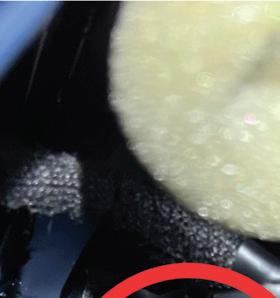
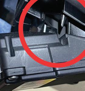
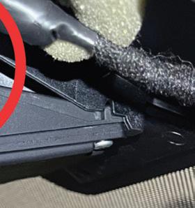
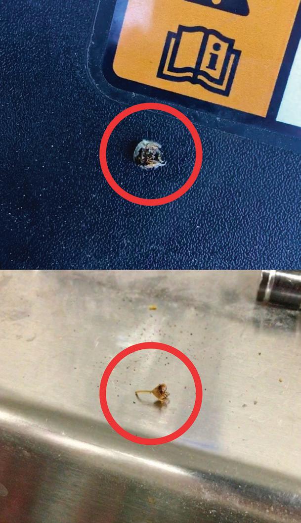
TWO 5TH GEN FORD EXPLORERS mere weeks apart mysteriously become no-starts after being worked on in the collision repair shop. The root cause ended up being debris that through the physics of the collision or work performed by a technician allowed debris to get around the air filter and become lodged in the mass air flow (MAF) sensor.
The industry structure makes this worse. Flat rate pushes a turn-andburn mindset. Diagnostics often does not pay in a way that rewards deep work. Advisors do not always want to sell every hour of diagnostic time because they feel pressure from the customer. Production flow pushes for fast answers so the next vehicle can get moving. Managers want updates. Phones ring. People interrupt the process in the middle of a line of thought.
Fast thinking is useful when it helps narrow what to test first. It becomes a problem when it causes the technician to decide what the fix is before the testing is done.
starts with the customer’s concern in detail.
What is the customer actually experiencing? When did it start? Under what conditions does it happen? Has the customer tried to fix it? If the vehicle came from another shop, what did that shop already do? What were their findings? If it came from a collision repair shop, I want to know the repair scope, what was replaced, and whether the parts used were new, used, or aftermarket.
From there, I scan the vehicle and look at the full picture. If there are a lot of DTCs, I do not lock onto one. I look for a possible correlation and ask whether multiple codes may point back to one failure. Then, I pull up system operation information. I want to understand how the system is supposed to work before I start deciding how it failed.
Next, I verify the condition and monitor the data points that look relevant. I do not want the flow chart biasing me too early if the live data is telling me something else.
After that, I work through the DTC information and rank possible causes from most likely to least likely or group the codes in a way that points to a common problem. Then I build a
round might be connections, corrosion, harness issues, aftermarket accessories, or obvious physical faults.
If I find the problem, I repair it and verify it. If I do not, I revise the hypothesis and start the next pass. That second run may go beyond the flow chart and move more into tests tied to how the system should operate. If I get deep enough into a problem and still do not have a clear answer, I bring in another technician for differential diagnosis.
That process is slower than guessing, but it is far more repeatable.
One thing ADAS teaches quickly is that not every electronic-looking problem is really electronic.
Early in my ADAS calibration work, I had a late-model Mazda Miata that
was having trouble passing blind spot monitor calibration with the Doppler box. My initial thinking was that the BSM module may have been damaged in the collision and was not receiving the Doppler generator signal at full strength.
I removed the rear bumper to verify module installation and check for unrepaired damage. I did not find any. Then I ran the calibration again with the bumper removed. This time it passed.
That changed the direction of the diagnosis immediately. I talked with the collision shop and found out the rear bumper cover had been repaired in the area of the BSM module instead of being replaced. A new bumper cover went on the car, and the calibration was completed without an issue.





That problem looked electronic. It was not. The system was affected by a physical repair condition.
I had another case on a 2020 Audi Q8 that drove this point even harder. The vehicle had a laser distance scanner replaced after a collision. I programmed the new module as required and then moved to calibration. The calibration failed. I adjusted the sensor. No change. I moved the target. No change. I ran the programming again. No change.
At that point, against my better judgment, I called the module bad out of the box. We all know the joke that “new” sometimes means “never ever worked.” I got another module, repeated the process, and got the exact same result.
Now, I was thinking firmware or programming path. I reached out for factory support. Their first response was to point at setup and environment. I knew that was not the issue, but I still documented everything: shop setup, photos, lighting measurements, and target specs.
That is when support came back and confirmed that the factory diagnostic software was not actually completing the programming routine
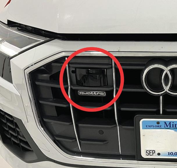
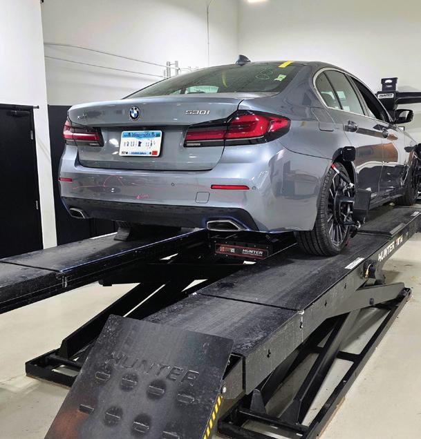
correctly on its own. An SVM code had to be entered for the programming to be applied correctly. Once that was done, the programming took and the calibration completed successfully.
That case stuck with me because it proved something important. Sometimes the diagnostic tool itself has to be questioned.
From there, I scan the vehicle and look at the full picture. If there are a lot of DTCs, I do not lock onto one. I look for a possible correlation and ask whether multiple codes may point back to one failure. Then, I pull up system operation information. I want to understand how the system is supposed to work before I start deciding how it failed.
Next, I verify the condition and monitor the data points that look relevant. I do not want the flow chart biasing me too early if the live data is telling me something else.
After that, I work through the DTC information and rank possible causes from most likely to least likely or group the codes in a way that points to a common problem. Then I build a hypothesis and start testing. The first round might be connections, corrosion, harness issues, aftermarket accessories, or obvious physical faults.
If I find the problem, I repair it and verify it. If I do not, I revise the hypothesis and start the next pass. That second run may go beyond the flow chart and move more into tests tied to how the system should operate. If I get deep enough into a problem and still do not have a clear answer, I bring in another technician for differential diagnosis.
That process is slower than guessing, but it is far more repeatable.
Another thing that gets overlooked is how often diagnostics start with bad information.
Sometimes another technician is trying to cover up something they did not do correctly. Sometimes a body technician accidentally damages a harness or gets weld spatter into a connector. Sometimes service information is incomplete or has misprints. Sometimes the customer tries to fix the car and leaves that part out because they do not want to admit it.
And sometimes the handoff to the technician is just, “Customer states the system does not work.” That is not a diagnostic starting point. That is a guessing contest.
Good leaders have to protect the diagnostic process from constant interruption. Good technicians must resist the urge to fill in missing information with assumptions.
I think the industry still underestimates what strong diagnostics require.
There has been a lot of hiring from outside the automotive field into ADAS work. That can be good. Fresh eyes are valuable. But, when people are trained only on a narrow frame of vehicle repair, they often do not have the foundation to reason across the full vehicle when something goes wrong.
The industry has also not done a
great job encouraging continuing education. On top of that, there is often no clear growth path for technicians who want to become diagnosticians. In some shops, the technician who gets deeper into diagnostics feels punished for it, either by pay structure, workflow, or constant pressure.
The takeaway here is not complicated.
Technicians need a dialed-in process for diagnosis. If they rely on judgment heuristics alone, they will get some lucky wins, but over time the losses will be greater.
Shops need to set customer expectations up front. They need to gather and pass along the right information. Service advisors and managers need to give technicians room to work without constant disruption. That can be handled with clear time marks for progress updates, so the technician knows when communication is expected.
SCAN THE QR CODE TO SHARE THIS ARTICLE AND READ RELATED ARTICLES ONLINE




Leaders also need to build better compensation plans, better cultures, and better work environments. If a shop wants strong diagnostics, it has to support the kind of thinking that strong diagnostics requires.
In modern vehicle repair, especially ADAS, the silver bullet mindset is not enough. The shops and technicians who will win are the ones who build a repeatable process, trust evidence over ego, and stay disciplined long enough to find the real root cause.
PAUL BOSTEL is a seasoned leader with over 20 years in the automotive industry. He is recognized as one of fewer than 2,300 ASE World Class-certified technicians — a distinction that underscores his mastery in diagnosing and repairing complex vehicle systems, with a specialized focus on ADAS. Paul is director of Advanced Vehicle Technology for Quality Collision Group, where he applies his analytical precision and strategic mindset to elevate operational performance and repair standards. In parallel with his automotive career, Paul has proudly served the Apple Valley Fire Department for over nine years and holds the rank of captain.






















METICULOUS PREPARATION, CORRECT PRODUCT USE, AND ADHERENCE TO REPAIR PROCEDURES WILL HELP ENSURE SUCCESSFUL OUTCOMES.
BY SHAWN COLLINS
Before any discussion around plastic bumper repair, it must be mentioned that it’s necessary to refer to the OEM service information to determine if it is recommended to do any repairs at all, if you can only repair in speci c areas, or if you can add to the paint coating’s thickness when re nishing. Some of these cautions related to ADAS sensor functions are safety requirements that must be strictly followed. ere are many other vehicle speci c recommendations that you will need to identify before you begin repairs.
The adhesive products used for plastic repair have never been more user-friendly and have helped to make repairs very simple and reliable. However, the key to successful plastic repair is using the specified adhesives in the exact manner for which they were designed. This is one segment of the repair where following the product maker’s instructions to the letter is directly linked to success. This is no place for replacing the product manufacturers’ information with tribal knowledge, YouTube hacks or benchtop chemistry. One of the main reasons technicians are reluctant to repair plastics is that they may have had a bad experience or failure in the past because they potentially strayed from the official instructions. The drawback to typical instructions or SOPs is that they only instruct technicians what to do, but it may be just as important to tell technicians what not to do. Below is a list of the most common plastic repair errors that technicians make, and avoiding these errors will vastly improve their chances for success.
Always follow the manufacturer’s instructions, but if you’re still having failures, these in-depth “do’s and don’ts” should be helpful. These tips align with the 3M Two-Sided Repair SOP, but they also pertain to the other plastic repair SOPs’ similar steps.
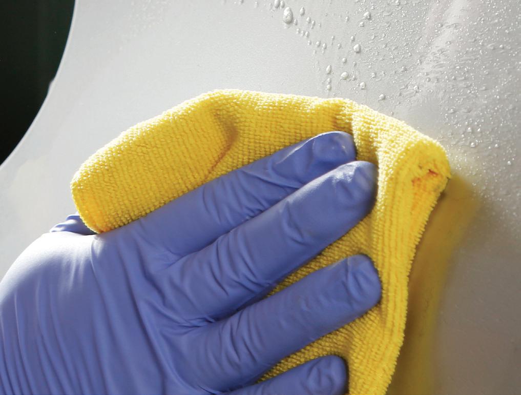
Do: Clean the entire bumper or part, not just the damaged area.
Cleaning the entire bumper will prevent remaining contaminants from being dragged into the clean repair area. More importantly, by cleaning the entire bumper, you may be able to identify additional damage that may not be visible while dirty. Damage like spider cracks, broken or missing tabs, stone chips or paint defects may be exposed after complete cleaning. Discovering unrepairable hidden damage after repairs are made can lead to wasted time on an unrepairable bumper.
Do not: Soak the plastic with liquid cleaners after removing the paint coatings. Using liquid cleaners after the repair area has been sanded to raw plastic creates an unnecessary risk of failure. Solvents can wick into the surface of the raw plastic and may take some time to escape. If adhesives are applied before the solvents can escape, it may cause adhesion failure. It’s best to use clean compressed air only to clean bare plastic areas.
Do: Clean with both soap and water and a VOC- compliant wax and grease remover or plastic cleaner.
Do: Thoroughly clean the back of the bumper. The OEM bumper suppliers coat the injection molds with a non-stick substance to prevent the bumper from sticking to the mold. They typically do not clean the unfinished back of the bumper before shipping.





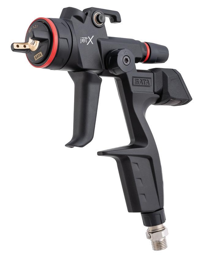
SATA jersey with any jet X purchase!








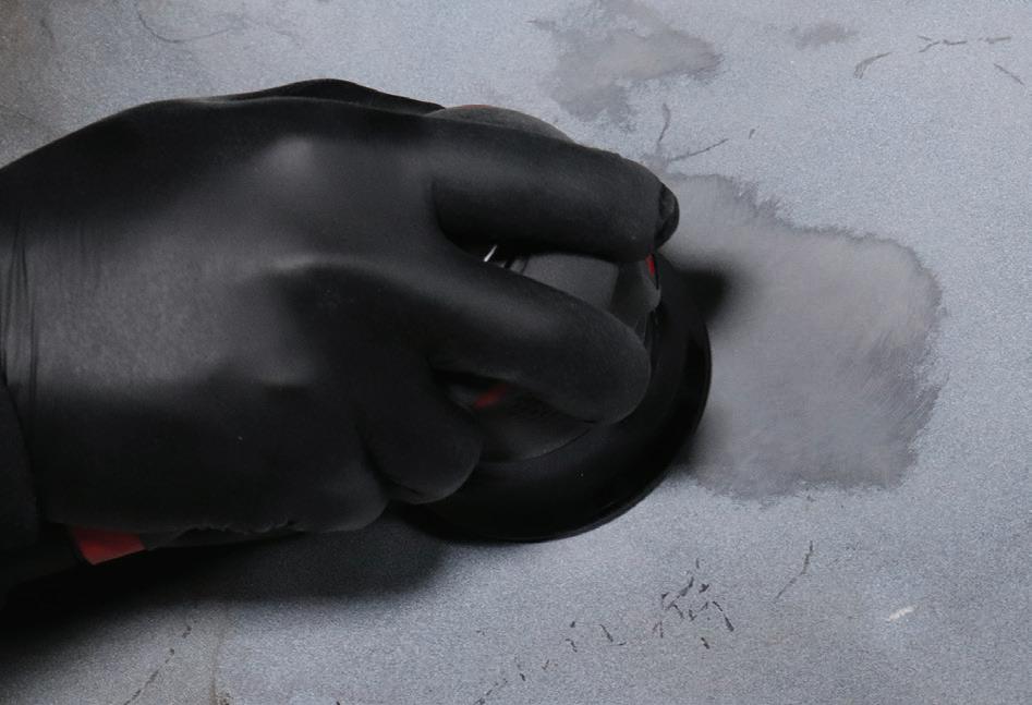
Do: Ensure that the crack or damage is perfectly aligned. An uneven surface will continue to pop up as you shapesand the cosmetic filler - making it difficult to make a smooth, even repair.
Do not: Taper the backside of the bumper. To prepare for back side reinforcement, it is only necessary to sand to rough up the surface thoroughly to create a fuzzy texture to create better adhesion.
Do not: Use a grinder with an aggressive grade grinding disc in place of a DA sander. A grinder is too aggressive and creates smooth melted scratches that do not bond to the adhesive well. Deeper scratches don’t achieve a better bond. Only grade 80 on a DA sander will create the fuzzy surface texture necessary to achieve a strong adhesive bond.
Do not: Use a liquid cleaner on the sanded surface, only clean, dry compressed air.
Do not: Soak the plastic with the adhesion promoter. A medium wet coat is best.
Do not: Rush the flash time for the adhesion promoter, especially in a shop colder than 70 degrees F.
Do: Use the adhesion promoter correctly and read the instructions. It’s critical to follow coat thickness and flash time guidelines to avoid failures. Adhesion promoter contains a chemical that etches or bites into the plastic surface. This creates a chemical bond to the plastic. When adhesive is applied, it will bond onto this etched surface, creating a strong mechanical bond. With both a chemical and mechanical bond, the chances for good adhesion vastly increase. If you are having problems getting a fine featheredge, you may have applied the adhesion promoter too heavily or may not have allowed enough time for it to flash off.
Do not: Mix product systems. Only use the adhesion promoter specifically recommended for that adhesive. Other adhesion promoters may work, but you are unnecessarily introducing another variable for failure.
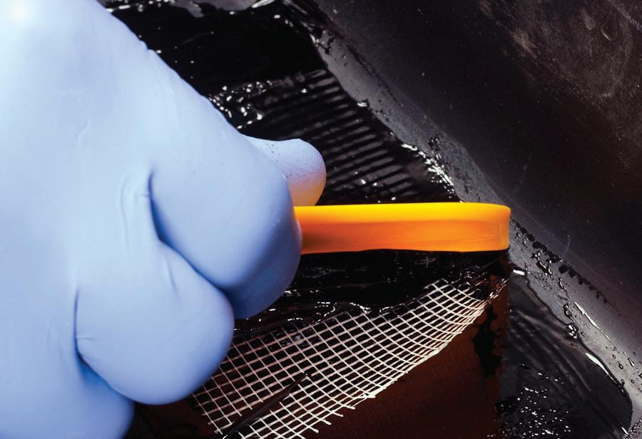
Do not: Apply the reinforcing patch directly to the plastic. Apply it to the wet-bed of adhesive. The cloth reinforcing patch doesn’t bond well to the plastic and decreases the surface area of the adhesive bonding surface.
Do: Immediately after you tamp the cloth into the wet adhesive, apply another layer of adhesive over the reinforcing patch. Work quickly, as the adhesive starts to cure quickly. Add more layers to achieve the desired thickness and strength. One or two layers are typically sufficient.
Do not: make a narrow “V groove” taper. The taper must be approximately 3” wide and have gradual sloped edges. Sharp edges will cause the repair to map or ghost over time.
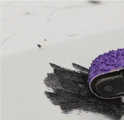
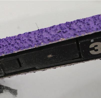


Do not: Grind or sand plastic bumpers at high speeds, which will melt or smear the soft plastic. Adhesives will not adhere to melted or smeared plastic and once the plastic is melted it will be difficult to correct the melted areas. Any melted or smeared plastic areas must be removed by sanding at slower speeds.
Do: Taper deeply enough to begin to expose the adhesive from the back of the bumper. This will allow the adhesive from the back side to bond to the adhesive on the front side and ensure the damage is repaired all the way through the thickness of the plastic.
Do: Make sure the sanded repair area has no grinder scratches or gouges. The surface must have a perfectly uniform, fuzzy texture.
This is a critical step because repair adhesives will not bond to shiny, smooth plastic. These areas may bubble up later, most likely during the bake cycle or in the sun. Meticulously sand low, shiny areas which will be identified by blowing off the repair area.
Do: Follow instructions for sanding the area surround-
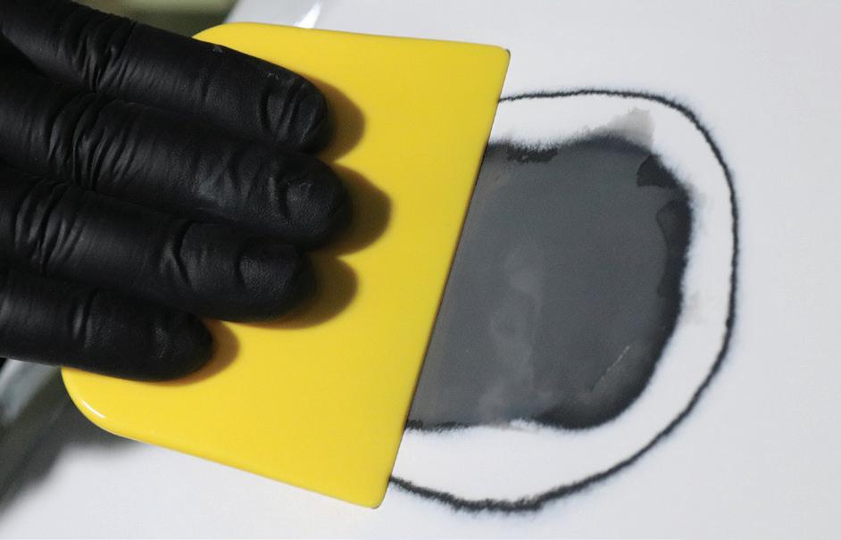
SAND THE SURROUNDING AREA large enough so that your adhesive application does not extend to the painted surface.
ing the dished-out area. Take care not to stray into the dished area where grade 80 is necessary.
Do not: Apply the cosmetic repair adhesive over the paint. To avoid this, be sure to sand the surrounding area large enough so that your adhesive application does not extend to the painted surface. Give yourself plenty of room, as feathering a larger area only takes a minute or so and will ensure that the adhesive featheredge winds up on the



plastic where it belongs and not on the paint where it’s likely to peel. Removing the paint with grade 180 about 3” to 4” all the way around the tapered area is usually sufficient depending on the size of the damage.
Do not: Sand with a grade 180 disc in the tapered area that you have previously sanded with grade 80.
Do: Be sure to equalize the adhesive cartridge and purge some adhesive from the mix nozzle before applying adhesive to the damaged area.
Do: Apply the adhesive to the bumper while keeping the mix nozzle tip submerged in the adhesive. This will avoid pinholes in the cured adhesive.
Do not: Apply the adhesive in a zigzag pattern or drizzle it onto the surface. This will entrap air and create pinholes.
Do: Apply enough adhesive to the damaged area allowing for some slight flowing of the adhesive as it sets up. Cupping the spreader slightly on the last wipe will leave more adhesive in the lowest area of the damage. Taking care to apply the adhesive neatly at this stage will make sanding easier. Clean up the edges with your spreader.
Do not: Rush the sand time especially if the shop temperature is colder than 70 degrees F. A few extra minutes or some gentle heat from a heat gun or lamp will ensure the edges feather well.
Do not: Sand at high speeds. Turn the DA down to an appropriate low speed and sand carefully. Sanding at high
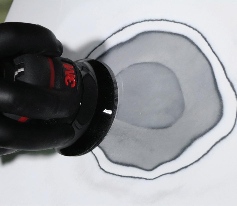
TO SAND FLEXIBLE FILLER , keep the DA sander moving with light to moderate pressure and a low speed.
speeds will create heat and soften the adhesive, especially where it is very thin at the outer featheredge areas.
Do not: Bear down with heavy pressure on the sander or sand continuously in one spot.
Keep the sander moving with light to moderate pressure. Let the sander action do the work. Too much pressure can create heat that can make it difficult to get a fine featheredge. If you’re having difficulties creating a fine featheredge, you are most likely creating heat with your sanding technique, or the adhesive isn’t fully cured for sanding.
Do not: Leave any stray grade 80 scratches in the adhesive or surrounding area. Be sure to thoroughly refine these scratches with at least grade 180, or they will be visible after refinishing.
Do: Use a block to do the final sanding to ensure the repair is straight.
Do: Carefully inspect for scratches or pinholes.
Do not: Fill pinholes with body filler or glaze. These products will fail to bond with the adhesive filler and bubble up later in the repair process or bake cycle.
Do: Only use the same cosmetic flexible filler that you made the repair with. Use the corner of a filler spreader to force the filler into the pinholes. Sand after curing.
Do not: Use the aerosol adhesion promoter that was used for the adhesive to coat the final repair. At this stage of the repair, always use the adhesion promoter recommended by the paint company prior to refinishing plastics.
Carefully following these tips and the product makers’ instructions will help eliminate possible repair failures. Taking a few extra minutes to be meticulous and thoroughly following the steps outlined will go a long way toward a quality repair.
SHAWN COLLINS recently retired as an advanced application engineer for 3M. He was an ASE Certified collision technician for 26 years and has been an I-CAR instructor for 19 years. He teaches more than 50 different training programs and is both a steel and aluminum welding qualification test administrator for collision shops and insurance companies.
SCAN THE QR CODE TO SHARE THIS ARTICLE AND READ RELATED ARTICLES ONLINE

WELDING STRIPS AND TEXTURED COATINGS ENABLE TECHNICIANS TO EFFICIENTLY RESTORE DAMAGED PARTS, MAINTAINING ORIGINAL TEXTURES AND MINIMIZING ENVIRONMENTAL
When you think about the amount of plastic that is on a vehicle today, sadly, most of that ends up in a land ll when a part is in need of repair. Surprisingly, one good change that came out of the COVID pandemic for body shops was the limited availability to obtain new parts, leaving technicians having to repair and re-use instead of simply disposing.
Not only is repairing the sustainable choice, but repairing can also help a shop’s bottom line. Due to supply chain and backorder issues, quickly and easily ordering replacement parts is still not a given. What if that same dented part could be repaired instead – faster, and for less money?
The first step the technician must take is to properly identify whether the OEM allows the plastic to be repaired. In some cases, the technician may be forced to replace it.
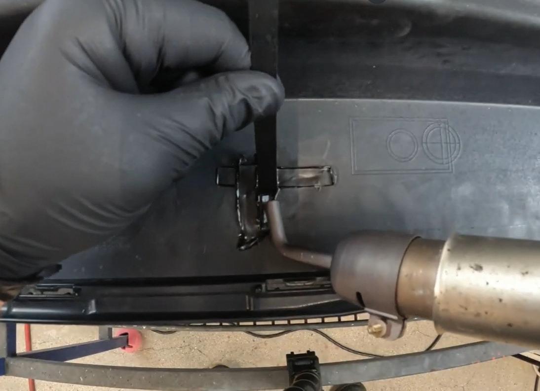
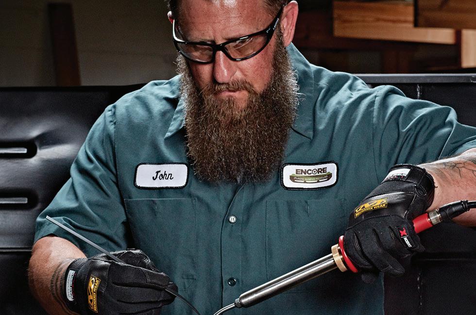
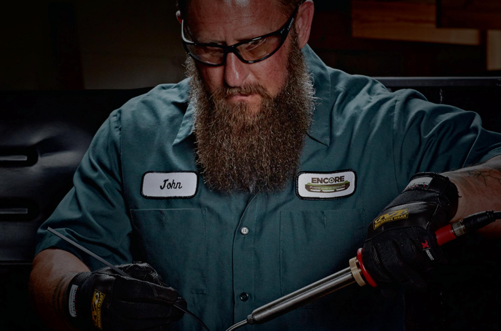
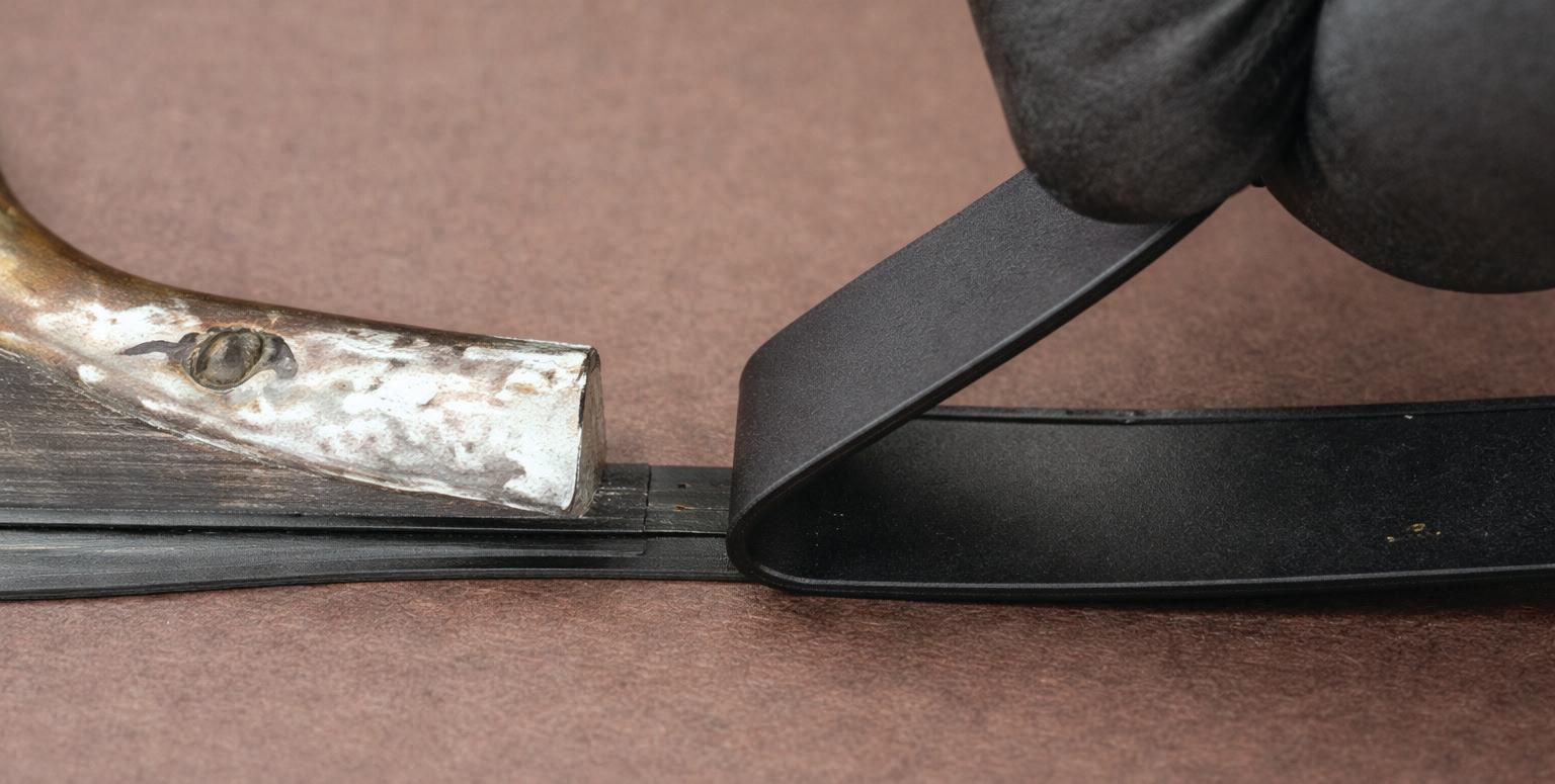
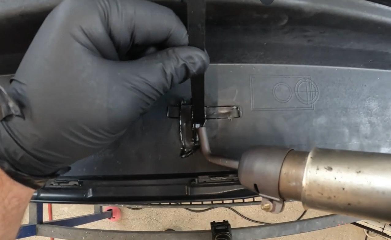
Plastic welding in difficult angles
If restoring plastic is an option, this will save time, money, and the
BY ALEJANDRA GALLEGO
environment. And there are multiple methods/products newer to the market that technicians may not have tried in the past.
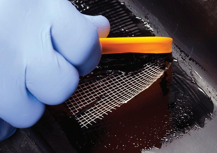
For years, there has been one standard way of repairing plastics. 4Plastic, in collaboration with SEM, developed plastic welding strips for repairing most plastics, including difficult angles. These automotive-grade strips are flexible and absorbent to stress and impact, while still being easy to shape and blend into the original part. Easy Weld Strips produce a strong repair and are easy to file, finish and use.
Industry research has shown that plastic welding demonstrates advantages over some traditional repair methods, particularly with minimal prep and improvements to impact resistance.
Whether restoring bumpers, headlights or tabs, rethink the plastic job: is replacing the only option, or can it be repaired to save money and waste?
Recent trends by OEMs have shown more textured plastics in manufacturing designs, challenging the repair industry as replacement textured components often did not match the existing faded plastic. Restoring those
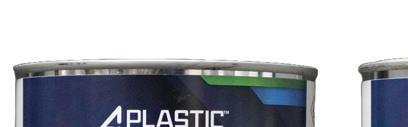
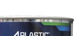
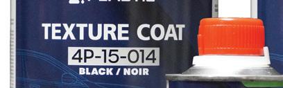
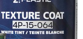
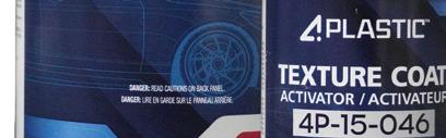
OEM-LEVEL SOLUTIONS allow techs to restore plastic components – such as bumpers, headlights, textured parts, and tabs – to their original strength and appearance.
new textures accurately has become a struggle. Now, new texture products are being developed to address this shortcoming.
Textured parts are often in lower, high-impact positions on the vehicle, making most of the damage minor and highly repairable. If a shop has the ability to restore these parts rather than replace them, it will not only reduce overall costs but create a more sustainable business because of less plastic waste and parts-related emissions.
The newest generation of texture coatings to come to market are specially engineered to address the need created from OEMs’ preference toward non-painted plastic parts.
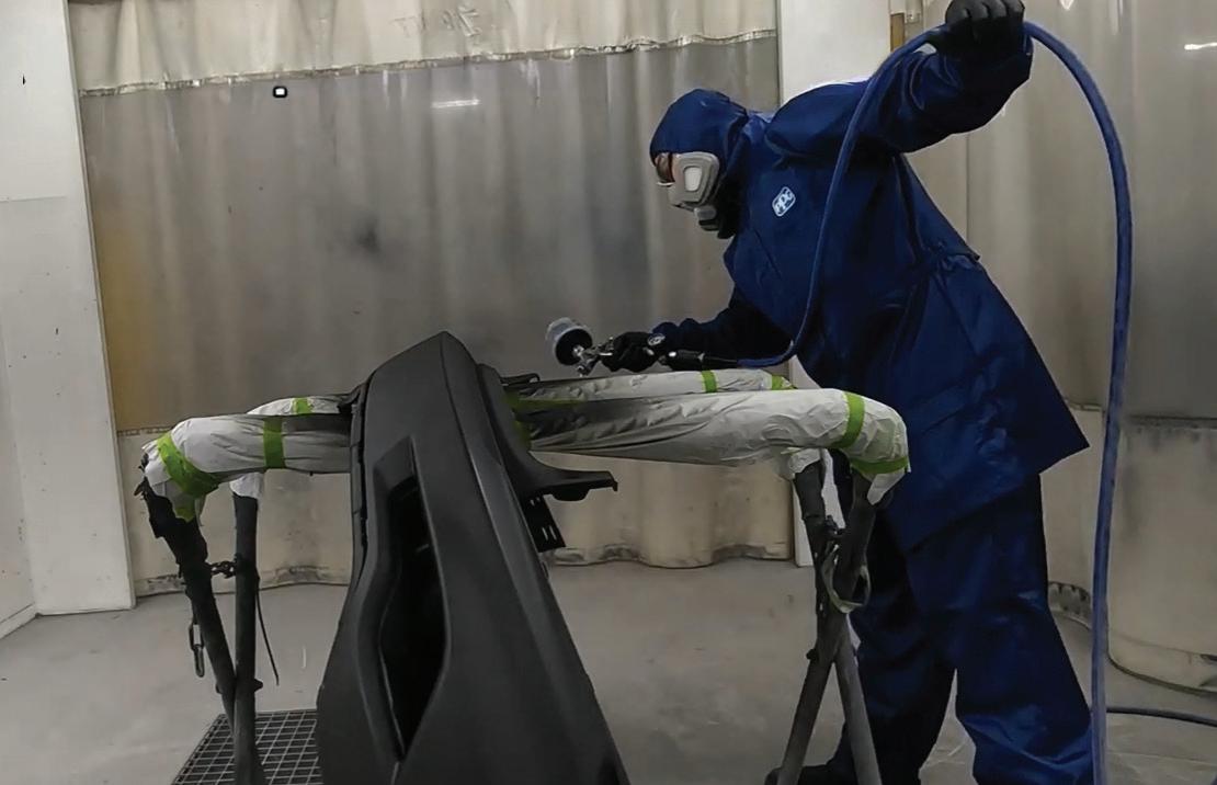
These new advanced coatings are formulated to replicate today’s most common vehicle textures. They have undergone extensive laboratory testing, including UV fade durability, adhesion, gravel impact resistance, and more performance testing. Though they sound complex, these products have also been designed for ease of use, so that even beginner technicians can achieve consistent results.
There are now also new 2K texture solutions on the market to address the growing demand for OEM-grade texture finishes. You can find all texture ranges, whether smooth or heavy grain, which are lab-tested to ensure consistency and durability. Multiple shades of black and gray are also available.
With many of these plastic parts sustaining only minor damage, it has become a true value-add if a technician has the ability to repair and retexture them.

GALLEGO has been with PPG for more than 20 years, contributing across multiple business units, including Refinish, Protective and Marine Coatings, Traffic Solutions, and, most recently, SEM as business director. Her career includes leadership roles in operations, continuous improvement, and cross-functional team development, with a strong focus on operational excellence and customer collaboration.
SCAN THE QR CODE TO SHARE THIS ARTICLE AND READ RELATED ARTICLES ONLINE

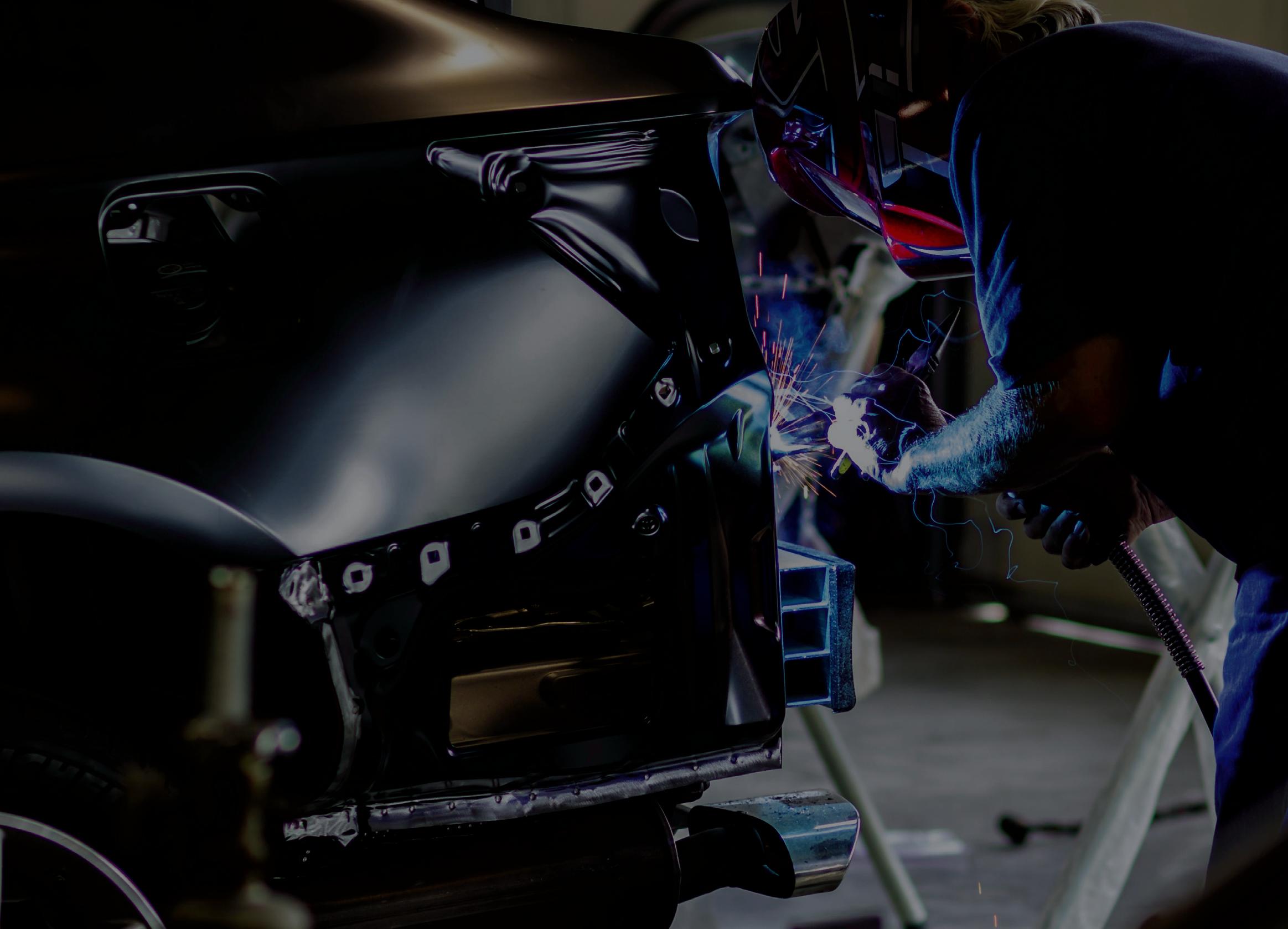
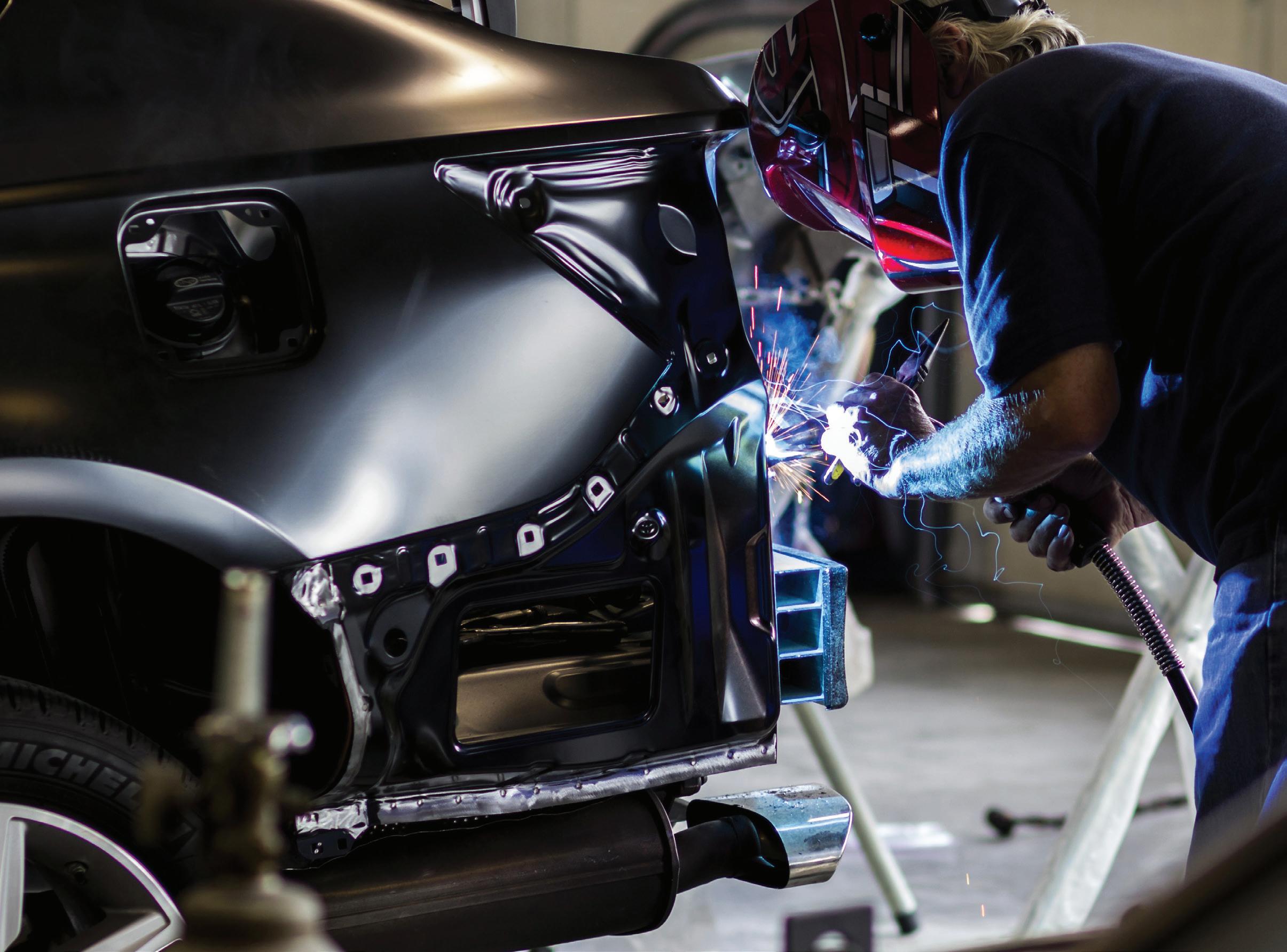














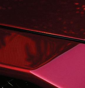
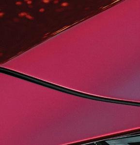
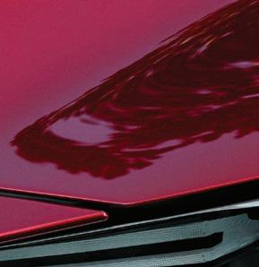
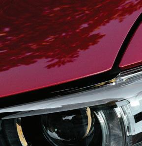
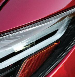
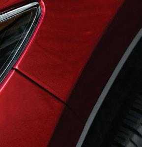
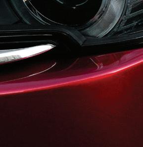
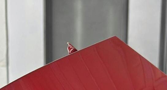
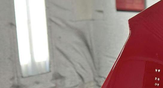
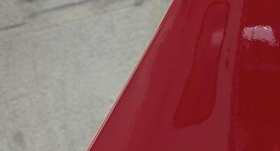
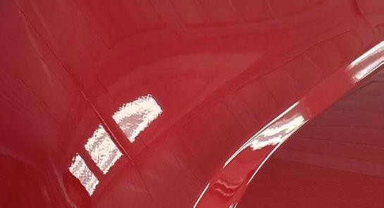
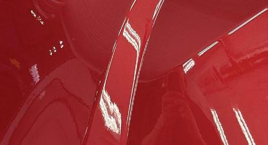
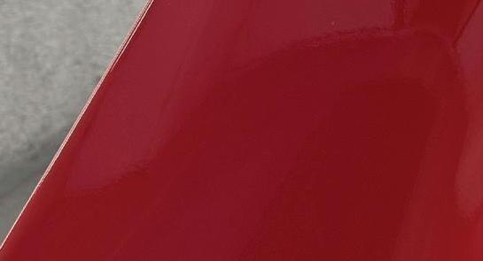
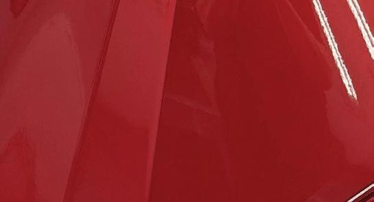
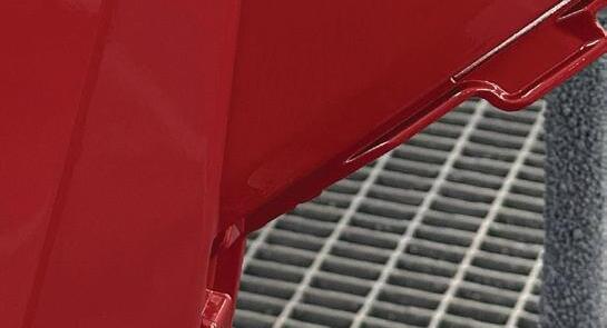
MAZDA’S 46V Soul Red Crystal, as seen on this CX-5, is often a quadcoat finish for multiple paint manufacturers and requires some additional color validation and preparation processes.




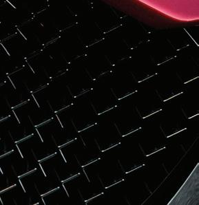

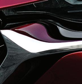


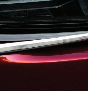







can the parking lot at your child’s or grandchild’s soccer match, and you’re likely to see a sea of monochromatic SUVs in white or various shades of gray. But although these “safe” colors remain the most popular, OEMs continue to introduce vibrant, visually interesting special-e ect colors that often require multiple stages or other unique procedures. Some have been around for more than a decade, but they continue to create challenges for painters not experienced in their application.
reaches the booth to include digital color tools, sprayout cards, and letdown panels, plus often planning to extend the blend area.
WITH THESE ARTICLES, HELP LEARN THE STEPS NEEDED FOR SUCCESS WITH THESE COMPLEX, VIBRANT COLORS.
BY JAY SICHT
For this topic, ABRN called upon the experts at PPG and 3M’s Skills Development Center for their views on what can provide the greatest chances of success in the paint booth. Their articles, which follow, provide some common pointers, but they also differ slightly in their approach.
As PPG’s Steven Matthews notes, preparing for these complex finishes should begin before the vehicle
3M’s Troy Knopik and Michael Nelson agree on the importance of sprayouts and letdown panels, but they also focus on the prepping process. 3M’s instructors teach painting processes using multiple manufacturers’ products, and they note that each manufacturer specifies the grit you should use to finish panels, which can be as fine as 3000 grit on blend areas. They also cover gun selection and flash times.
These multi-stage colors often give painters cause for pause, but with training, repetition, and process discipline, they can grow more confident.
We hope you and your team find these tips to be helpful in your quest to achieve invisible repairs and proper compensation for the additional steps required in their processes.
DIGITAL TOOLS, PROPER PLANNING, AND COMMUNICATION CAN HELP ACHIEVE ACCURATE COLOR MATCHES, REDUCING REWORK, AND MAXIMIZING SHOP EFFICIENCY WHEN WORKING WITH COMPLEX SPECIAL-EFFECT FINISHES.
BY STEVEN MATTHEWS
Automotive color design has changed dramatically in the past decade. Many automotive manufacturers now rely on layered coatings that create depth, movement, and color travel that simple metallic finishes cannot achieve. These finishes attract buyers in the showroom. They also create new challenges in the collision repair shop.
Painters often pause when a vehicle with a special-effect color enters the shop. Hesitation usually comes from uncertainty rather than true difficulty. Multi-layer colors require planning, discipline, and not guesswork. When technicians follow a structured process, these repairs become predictable and profitable. Mazda’s 46V Soul Crystal Red provides a useful example of how modern multi-layer colors work and how technicians can approach them in a repair environment.
A practical approach
Consider Mazda’s 46V Soul Crystal Red as an example. Preparation starts before the vehicle reaches the spray booth. In most repairs, digital color tools provide an accurate starting point and often eliminate the need for traditional multi-step verification. However, for complex special-effect colors, additional
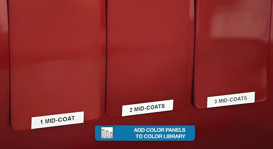
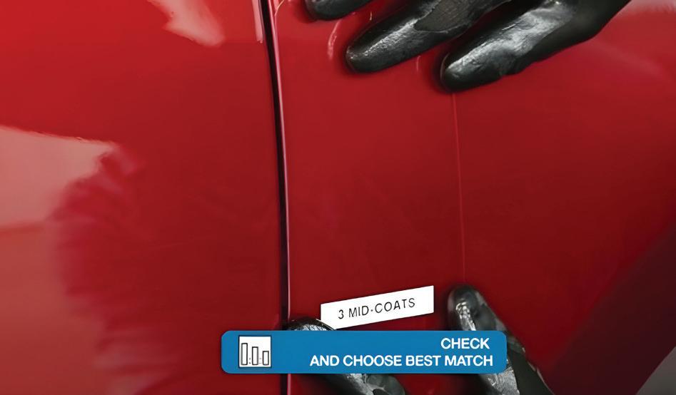
validation steps can still be beneficial. Technicians may begin with a sprayout card using the same spray technique planned for the repair. The sprayout can help confirm the formula selection and establish a baseline for comparison against the vehicle.
Next, the technician should create a mid-coat let-down panel. This panel contains several incremental layers of the translucent mid-coat. One section may receive two passes. Another receives three. The next receives four. This simple step removes guesswork. The painter can place the panel against the vehicle and determine which layer count matches the original finish.
The technician should also evaluate blend space before spraying the vehicle. Multi-layer colors often require blending into adjacent panels to produce a natural transition. The painter should check whether there is enough room to blend the paint smoothly into nearby panels. If there isn’t, the repair plan may need to be changed before painting begins.
These preparation steps take time, but they prevent expensive corrections later.
Technicians sometimes try to match the manufacturer’s exact process. However, collision repair equipment works very differently from factory paint systems.
Automotive manufacturers often use turbo bell atomizers that spin at 35,000 rpm. These systems atomize coatings to an extremely fine level and apply very thin layers. Many systems also rely on an electrostatic application that pulls paint particles toward the panel surface.
The spray pattern from these devices forms a cone shape rather than the fan pattern produced by a conventional spray gun.
In contrast, refinish technicians work with handheld spray guns that produce thicker film builds. Technique and orientation influence coverage much more than in an automated factory system.
This difference becomes easier to understand when compared with a traditional candy finish used in custom painting. Candy finishes rely on a reflective metallic or silver base, followed by multiple layers of a transparent tinted coating. Each additional layer deepens the color and creates the rich “candy” appearance often seen on show cars or custom motorcycles.
Many modern OEM special-effect colors operate on a similar visual principle. They use a reflective basecoat followed by a translucent mid-coat that controls color depth and movement. The difference lies in the need for repeat-
ability and production efficiency.
For that reason, refinish systems often include a dedicated mid-coat layer that helps recreate the depth and color movement seen on the production vehicle.
The goal of collision repair is not to duplicate the factory process. The goal is to reproduce the visual effect.
Many technicians hesitate when they see a multi-stage color on the repair order. The hesitation usually stems from limited experience with the process. Some painters worry that the job will consume excessive booth time. Others worry that the color will not match.
Most of these concerns fade after a few successful repairs. Once painters understand how the layers interact, the process becomes predictable. Preparation and verification replace uncertainty. That’s why training and repetition play an important role in quickly building confidence.
Most issues with special-effect colors result from skipped steps rather than technical limitations.
The first mistake is skipping the sprayouts when additional validation is required. Without that verification, the technician enters the booth without confirming color accuracy. Another common error involves ignoring the midcoat let-down. The painter then guesses how many layers will match the vehicle. Even small variations can produce noticeable differences in color tone.
Panel selection also matters. Repairs that leave little room for blending often create visible color breaks. Technicians should evaluate the repair area early and confirm that adequate blend space exists.
Finally, some painters rush the blend process. A controlled transition across adjacent panels remains the most reliable way to hide minor color differences. Attention to fundamentals prevents most mismatches.
Modern color matching relies on a combination of technology and technician skill.
Digital color tools, such as PPG DigiMatch spectrophotometer, cloud-based digital color software PPG LINQ Color with PPG VisualizID digital color visualization tool, help technicians identify the closest color variant. These systems analyze the existing finish, compare it with thousands of stored formulas and guide the technician to the best starting point for the repair. In most standard repairs, these digi-
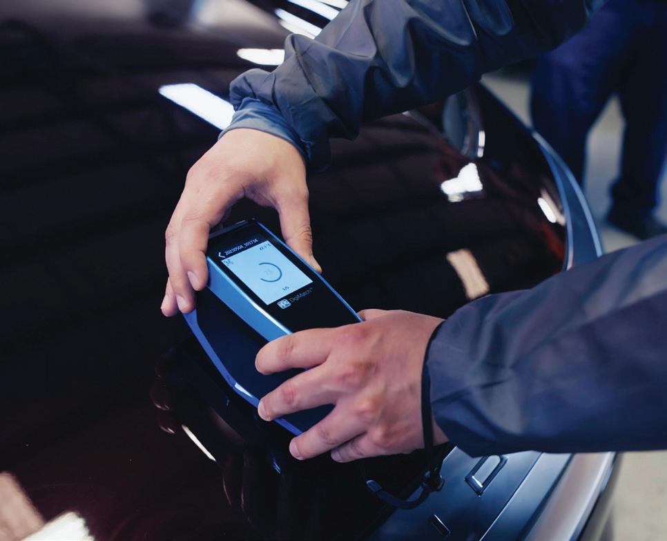
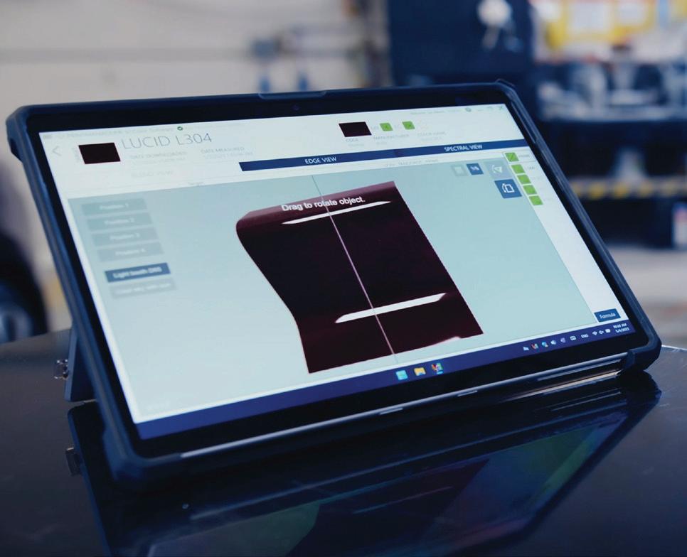
tal tools can replace traditional sprayouts and significantly reduce process time.
For more complex special-effect colors, technicians may still choose to perform targeted verification steps, such as sprayout cards or let-down panels. Adequate blend space also plays a critical role. Blending into adjacent panels allows the painter to transition color gradually rather than forcing a hard-edge match.
Technicians should also review product technical data and application guidelines before spraying. Technical bulletins provide valuable guidance on film build, flash times and recommended techniques.
Special-effect finishes often involve more than a simple basecoat and clearcoat repair.
In some cases, the special-effect finish could require two full processes. This is commonly referred to as a “quad-coat.” In this situation, the technician may sand and seal the repair area then apply clear. After that stage, the surface of the repair area would require additional sanding with finer-grit sandpaper once it has dried, before the technician applies the color layers and final clearcoat. Each step requires labor, booth time and materials.
Shops should document these steps clearly during the estimating process. Mixing room software can help track material usage. Photo documentation can help explain the process when questions arise.
Communication between estimators and painters remains essential. When the estimating team understands the required steps, they can write a repair plan that reflects
the real effort involved. When shops approach these repairs correctly, they can charge appropriately for the skill and time required.
Special-effect finishes will continue to grow in popularity as manufacturers push automotive color design forward. These finishes highlight the craftsmanship of today’s technicians. They also reward shops that focus on preparation and process.
Special-effect finishes require planning, accuracy, patience and communication. While digital tools now handle most color matching needs, technicians who perform extra validation steps when needed remove much of the uncertainty from the repair. With the right preparation, these visually complex colors become routine work rather than high-risk jobs. With proper planning and documentation, shops can deliver exceptional results and charge appropriately for the skill involved.

STEVEN MATTHEWS is a PPG technical and training director, Americas, Automotive Refinish. He brings more than two decades of experience in the coatings industry, including technical, operations and field support roles at PPG. For more on the Automotive Refinish business, visit here.
SCAN THE QR CODE TO SHARE THIS ARTICLE AND READ RELATED ARTICLES ONLINE


















BY MICHAEL NELSON


LEARN ESSENTIAL TECHNIQUES, INCLUDING SURFACE PREPARATION, SPRAY TECHNIQUES, AND FLASH TIMES, TO ACHIEVE INVISIBLE REPAIRS AND CONSISTENT COLOR MATCHES.



CONSISTENT COLOR MATCHES.



ne of the more recent trends in automotive refinishing has been unique and vibrant OEM multi-stage colors. Mazda 46G, 46V, and 51K are some examples of such colors, but they aren’t the only ones giving painters di culty.
These new colors often require new toners, reducers, and equipment. They also require new techniques to achieve an invisible repair. With consideration for prepping, mixing, flash times, sprayouts and application of products, here’s what painters may consider when spraying these challenging colors to achieve successful results.
Prepping
Prepping panels — especially the blend panels — is just as important as spraying them. Many of the new colors have extremely fine metallics in them. This can cause a couple of issues.

Fine metallics will follow the contours of sand scratches if not refined properly, and you will see every scratch. Most specialty colors that include ultra fine metallics, colored metallics or special pearls will have a technical data sheet that cover painting that specific paint code. The paint manufacturer may also have a TDS specific to the toner itself, which would provide rules to follow when any formula includes that toner. Every manufacturer has a specific grit to finish panels, so double check them before you start the job. The grit recommendations, depending on the manufacturer, can go as fine as 3000-grit on blend areas.
Another common issue when dealing with very fine metallic toners is that metallics will generally follow the contours of the texture underneath them - so if you don’t flatten the blend areas or sealer edges out sufficiently, it may show texture under the basecoat.









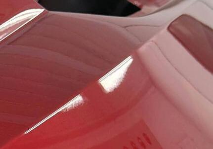






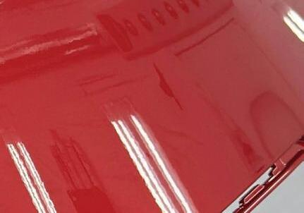
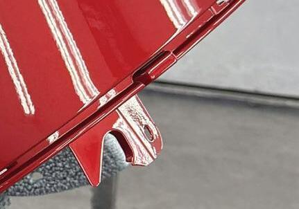


This vibrant tri-coat is Toyota’s 3U5 Supersonic Red, sprayed by veteran painter and social media influencer Josh Sorel, who posts on multiple channels as Josh Refinish.






















One other important tip when prepping these delicate blend panels is to skip the scuff pads. Scuff pads are usually acceptable for prepping blend panel edges, but when you’re dealing with these fine metallics, the inconsistencies in scratches from scuff pads may cause a problem. If you are using a fresh pad with moderate to heavy pressure, you may leave some aggressive scratches (even with a gray pad), so it’s best not to use them. It’s best practice to hand-sand edges with the appropriate grit sandpaper before machine sanding the main part of the panels.


THIS VIBRANT TRI-COAT is Toyota’s 3U5 Supersonic Red, sprayed by veteran painter and social media influencer Josh Sorel, who posts on multiple channels as Josh Refinish.
WHEN A PAINT COMPANY recommends a certain fluid tip size, it’s because it gives you the best chance of success in getting tricky metallics to lay down similarly to how they are laid down from the factory.
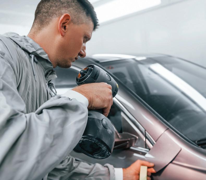


Because of their complexities, many of these new colors can vary significantly from year-to-year and model-to-model. So even if you have an existing sprayout or two, chances are you’ll need to do some work matching the color. Of course, a previous sprayout is the best start, but if you don’t have one that matches, you’ll have to use your camera and/or variant chips if available. If you’re using a camera, make sure to use both compound and polish on the part of the car where you’re doing a camera reading. The better the preparation of the area for a camera read, the better the camera reading will be. Don’t forget to clean off the buffing residue with a cleaner or inspection spray, as that can also cause a poor camera reading.
This is an instance where it may be best to include both the manufacturer and the paint code with the camera read, rather than just doing an open search without parameters. Of course, spraying out the camera-selected color is necessary to verify the color. If you do have variant chips avail-
3M scuff pads. Scuff pads are usually acceptwith the appropriate grit sandpaper before ma-
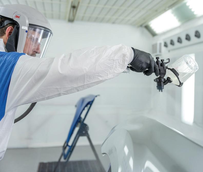
EVEN IF you have an existing sprayout or two, you’ll likely need to do some work to match the color.
able, and one of them looks like an acceptable match, it’s still best practice to conduct a sprayout to verify that the color matches the chip.
When it’s time to make your sprayouts, you will need to make sure you’re doing them properly. Taping a sprayout to a paint stick and holding it at arm’s length isn’t going to cut it. Instead, consider taping it to a large piece of masking paper on the booth wall, or to cardboard on a stand and setting it up vertically for spraying.
Spray an area larger than the card to get an even application of material, which is even more important when spraying mid-coats in three and four stage paint jobs. Each coat of mid-coat will need its own card. Making a letdown panel on a single card doesn’t give you a large enough sample to properly judge the amount of mid-coat needed. When making these cards, it is essential to follow the flash times, mix ratios, and application methods exactly to the letter according to the special TDS. Don’t rush this part, as any cut corners can lead to inaccurate test panels which could cost you later when you have the vehicle in the booth.
When you are selecting a color, try to lean toward newer formulas that have newly released toners if possible. Paint companies are only going to make a new toner if they can’t make it work with existing toners, so get the new toners and use them.
Using the proper equipment to tackle new colors is important too: certain colors have a recom-
mended fluid tip size, and that will vary depending on the paint manufacturer. If a TDS calls for a 1.1 fluid tip, use it. When a paint company recommends a certain size, it’s because it gives you the best chance of success in getting tricky metallics to lay down similarly to the way they are laid down from the factory. Dialing back a spray gun with a larger fluid tip isn’t the same as using the proper size. If you don’t spray these colors often, reach out to your distributor technicians or your paint manufacturer’s technicians and see if they have a loaner gun with the proper tip size.
Now that you have the color chosen and a proper spray gun setup, it’s time to spray the vehicle. The first thing to do is to review the TDS again to make sure you follow the proper procedure during the painting process. Pay special attention to the recommended reduction, as often these tough colors will require a special, more diluted reduction. For example, some 46G formulas require a black basecoat to be applied under the mid coat, while others require a black sealer. If sealer is to be applied, make sure you refine it to the recommended grit after it’s dried to avoid any sand scratch marks that could show after the basecoat is applied.
Many versions of that color will require a smaller fluid tip with over-reduced mid coat and need to be sprayed as a thin mist coat. They are often sprayed in a crisscross pattern to avoid striping. The thin mist coat helps the metallics in that color to lay flat to avoid looking too coarse on the face and the sidetone. Mazda’s 46V is another color that sometimes requires thin mist coats before the tint coat.
It’s extremely important on both of those colors to observe the recommended flash times to keep the flake lying properly. If you spray the next layer before the mist coats are fully dried, you risk moving the metallics and making the mid coat coarse and blotchy. The same goes for the tinted mid coat on 46V.
Mazda’s Rhodium White, or 51K, is generally the easiest of the three. This white tri-coat has a small amount of special metallic and pearl in the mid coat. The ground is sprayed like a traditional three stage ground coat, but the mid has similar flake, so the mid coat application is similar. Again, it’s generally light mist coats of over-reduced mid. If it starts to look blotchy, you’re probably spraying the mid coat too wet. Raising your gun speed and tightening your overlap at the recommended distance will help to keep the flake even across large panels. Make sure to wait the required flash times before applying clear.
Once you spray a few of these colors, they’re not so intimidating. Keep in mind they will usually take much
longer than a traditional paint job, so factor that in when planning your booth schedule for the day. Also, don’t be afraid to ask for more blend room. If it’s even in question, blend the next panel.
Finally, take your time. Follow your TDS for flash times and don’t rush. Having a redo on one of these jobs can be devastating for production, so make sure you get it right the first time. Once you get more familiar with these more challenging colors, it may be easier for you to enter the booth with confidence and feel positive that your paint job will turn out great.
TROY KNOPIK is a lead refinish trainer at 3M Collision’s Skills Development Center. Troy has been in the collision industry for over 35 years. He spent 25 years as a production painter before becoming a paint manufacturer representative for BASF. He trains painters across the country on all aspects of the collision repair process.
MICHAEL NELSON is a refinish trainer at the 3M Skills Development Center. Michael has served the collision industry for 29 years. He previously held production painter and product specialist roles for Finishmaster and Axalta Coating Systems. He trains painters and preppers from across the country on all aspects of the collision repair process.
SCAN THE QR CODE TO SHARE THIS ARTICLE AND READ RELATED ARTICLES ONLINE




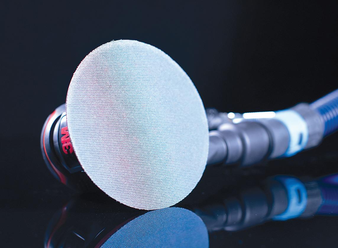
3M Hookit Blue Net Abrasives feature an engineered ceramic and aluminum oxide mineral blend with an increased attachment strength to a net backing that can help provide 95% dust extraction and less abrasive loading from body filler, glaze, primer and other paint coatings, when paired with the 3M Clean Sanding System or similar setups. The new design also provides better hook-and-loop pad attachment, increased edge retention, and excellent resistance to wrinkling, stretching and tearing, including on edges and contoured surfaces. The line includes 8”, 6”, 5”, and 3” net discs as well as 10-meter-long net sheet rolls in either 70-mm or 115-mm widths.
FENDERBENDER.COM /55372227
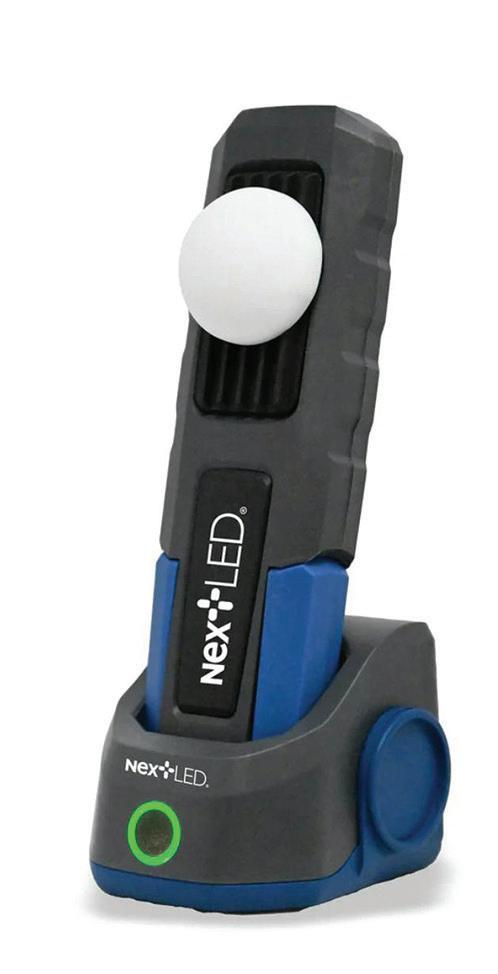
The NextLED Rechargeable ColorMatching Light, No. NT-6692M, is a CRI 96+ rated light with five color temperatures (2,700K, 3,500K, 4,500K, 5,500K, and 6,500K) for critical color-matching and identifying imperfections. The light features a detachable diffuser which eliminates glare and reflections, a multi-mount charging base, a dual light mode for lighting flexibility, and an extended 3-year warranty. The light has a maximum flood brightness of 500 lm and a maximum spot brightness of 200 lm. Powered by a 3.7V, 4,000 mAh rechargeable lithium-ion battery. It charges in 4.5 hours and is IPX6 water-resistant.
FENDERBENDER.COM/55353663
The Diagnostic Scan Tool, No. ET9150, from Mac Tools is an advanced, Android-based device designed for professional vehicle diagnostics. It offers OEM-level coverage for U.S., Asian, and European vehicles (1996 and newer), supporting protocols like CAN, CANFD, DoIP, and standards such as J2534.
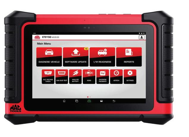
Key features include bi-directional controls, TECH 2 TECH remote diagnostics, Smartlink Remote Diagnosis, and instant VIN auto-detection. The ET9150 provides real-time voltage monitoring, comprehensive vehicle health reports, and professional repair information powered by Identifix. It also supports optional modules for ADAS calibration, immobilizer, and battery services, making it a versatile tool for technicians.
FENDERBENDER.COM/55372062
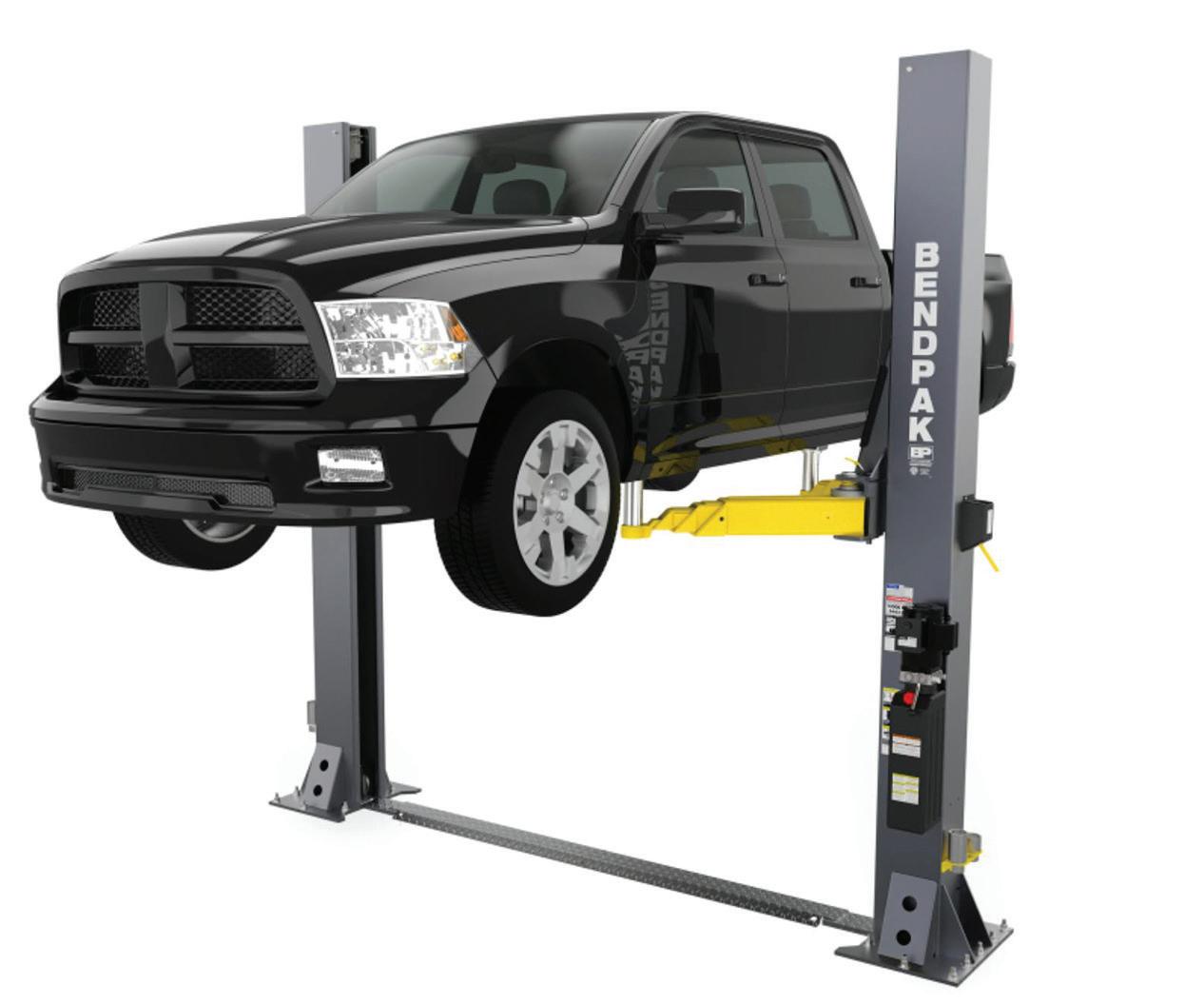
The BendPak 12APF Open-Top Two-Post Lift, No. 5175670, is a heavy duty open-top two-post lift engineered for shops that need maximum vertical clearance and real lifting power in low-ceiling environments. With a full 12,000-lb capacity, an exclusive Bi-Metric arm design, an ultra-durable floorplate with concealed hydraulics, and BendPak’s fortified ASARS automatic arm restraint system, this lift is built for serious daily use.
FENDERBENDER.COM/55372069
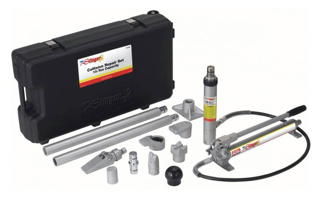
The 10-Ton Collision Repair Set, No. 1515B, from OTC is equipped with a single-speed hydraulic hand pump that features an automatic overload system to prevent equipment damage, a ram with a 6” stroke, and a 1/2-ton hydraulic spreader tool with 2” jaws that spread from 5/8 of an inch to 3- 3/8 of an inch. Included extension tubes are built sturdy to withstand tough situations, and designed to snap together for easy assembly. Industry standard couplers ensure compatibility with existing tools, as well as most OEM units.
FENDERBENDER.COM/55372055
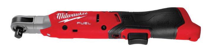
The Milwaukee Tool M12 FUEL 3/8” Ratchet, No. 3053-20, features a brushless outer rotor motor designed to deliver 70 ft-lbs of torque to break away stubborn fasteners, and 400 rpm to remove and install fasteners at higher rates of speed. The ratchet’s compact head and body size allow users full body access in tight spaces, maintaining a 3/4” head profile. It also features a new-to-world modular trigger cap, allowing users to switch between various button or paddle trigger configurations for customizable comfort. Equipped with a targeted LED worklight, battery-isolated system, and optimized forward/reverse shuttle.
FENDERBENDER.COM /55372066
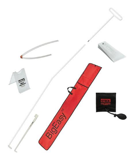
The BigEasy 8-pc Vehicle Access Kit, No. STC32902-KIT, from Steck Manufacturing, is a professional-grade vehicle access solution engineered for speed, control, and versatility. This all-in-one kit combines the proven strength of the BigEasy 8-pc Vehicle Access tool with the Easy Wedge, plus the added advantage of the RodLOCK design. This technology allows technicians to add extensions quickly and securely, maintain control during long-reach applications, prevent separation or slippage under pressure, and adapt to a wide range of vehicle sizes and access challenges. The access tool is built with a high-visibility glow-inthe-dark coating for low-light conditions. The included Easy Wedge creates a safe opening between the vehicle door and frame.
FENDERBENDER.COM/55372064
The Snap-on Pass Thru Assistant+ is a J2534 programming device that combines the turn-key remote support offered by the Pass Thru Assistant (PTA) with the DIY functionality of the Pass Thru Pro. This device offers J2534 flash programming services performed remotely by OEM-trained technicians for domestic, Asian, and European vehicles.
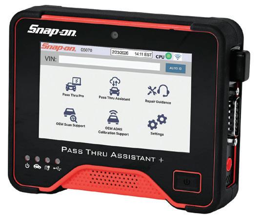
Users have access to OEM-trained brand specifc master technicians to provide remote repair guidance for complex vehicle systems. ADAS support and calibration can be performed remotely by the team of specialists. Functions as a standalone J2534 vehicle communication interface when used with a PC and OEM-purchased subscriptions.
FENDERBENDER.COM/55372070
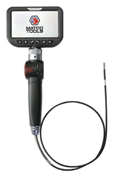
The Articulating Borescope w/ Screen, No. MDSCOPE39SC, from Matco Tools, is an ultrathin 3.9mm inspection camera that articulates 180 degrees in both directions to give technicians access to tight engine bays and confined areas. It delivers precise visual inspections of narrow piping, small engine ports, and other cramped mechanical spaces that larger cameras can’t reach. The 5” highdefinition IPS screen and three adjustable brightness lights provide increased illumination so the user can identify cracks, corrosion, or blockages.
FENDERBENDER.COM /55372075
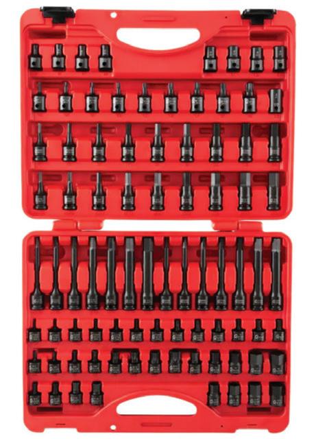
The SUNEX Tools 3/8” Drive
84-pc Master Impact Bit Socket Set, No. 3569, mixes hex, star, external star, tamperproof, and triple square driver coverage with core impact socket service in one assortment. The 3/8” drive with SAE and metric coverage keeps standard sockets and specialty drivers together in one set. Designed to help technicians cover common impact socket and specialty driver interfaces.
FENDERBENDER.COM/55374574
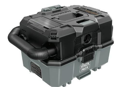
The FLEX Power Tools STACK PACK 2.5 Gallon Wet/Dry Vacuum, No. FX5231-Z, cleans up spills, dust, and debris with up to 63 CFM and 82” of water lift. The wet/dry vacuum cleaner features a HEPA filter that filters 99.97 percent of particles .03 or larger, plus a push-button filter cleaning function that clears filter debris buildup. The wet/dry vac is compatible with a hoseor tool-mountable wireless remote for quick, accessible control. Onboard storage for the included nozzles and attachments like the utility nozzle, crevice tool, utility nozzle brush, and 1-1/4” hose adapter. It attaches select STACK PACK storage solutions for easy transport to and from the jobsite.
FENDERBENDER.COM/55374577
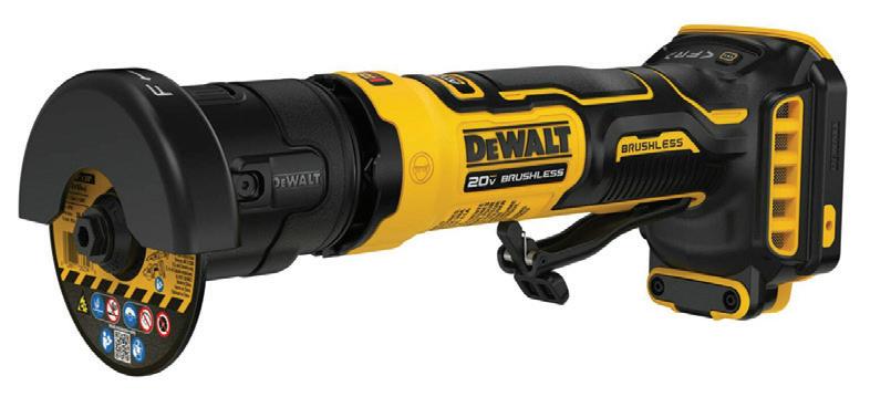
The DeWalt ATOMIC 20V MAX 3” Cut-Off Tool, No. DCG430B, makes straight, clean cuts in tight or narrow spaces. Engineered for tough metalworking applications, this tool is equipped with the DeWalt Anti-Rotation System to help maximize control. According to DeWalt, this tool delivers 78 percent more power than 0.5 hp-rated pneumatic 3” cut-off tools.
FENDERBENDER.COM /55372061
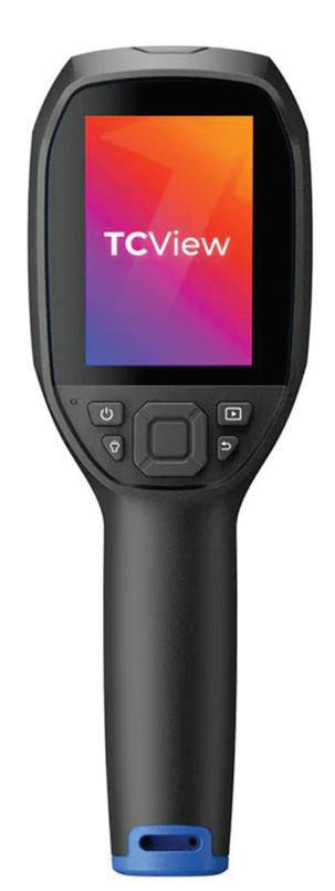
The TOPDON Handheld Thermal Imaging Camera, No. TC005, is a professional thermal camera built for precise, measurable inspections. It features 256x102 IR resolution with TISR-supported image processing, bumping it to an effective 512x384. The camera is designed to deliver clear thermal detail for electrical, industrial, and technical work. An integrated visible-light camera and built-in laser distance measurement provide added context and accuracy during inspections.
FENDERBENDER.COM/55372073
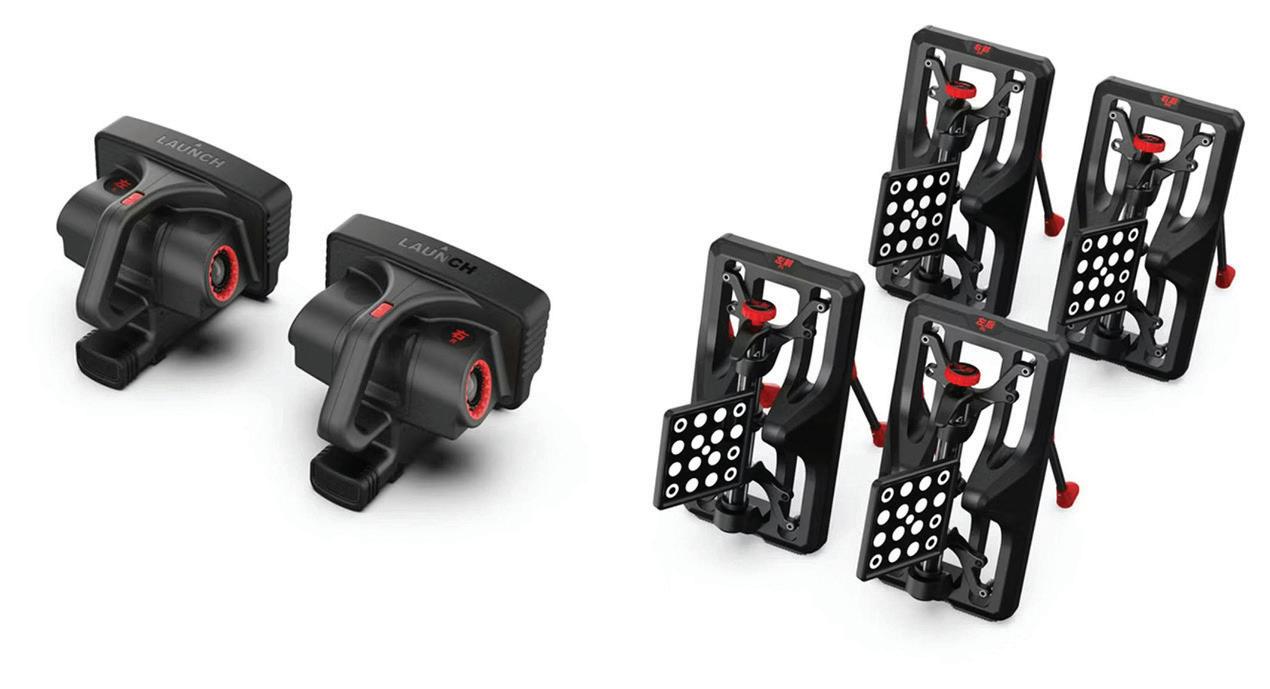
The Launch Tech X-613 Portable 3D Wheel Aligner is a wireless 3D wheel aligner designed with a streamlined industrial structure. It eliminates the traditional beam and cabinet setup, utilizing two magnetic measurement units and four-wheel clamp targets. These components enable four-wheel alignment detection through wireless networking communication. The design prioritizes functionality and portability, allowing the X-613 to be deployed in various workshop settings. Its setup does not require installation, wiring, or calibration, making it suitable for both fixed workshop use and mobile service operations.
FENDERBENDER.COM /55374575
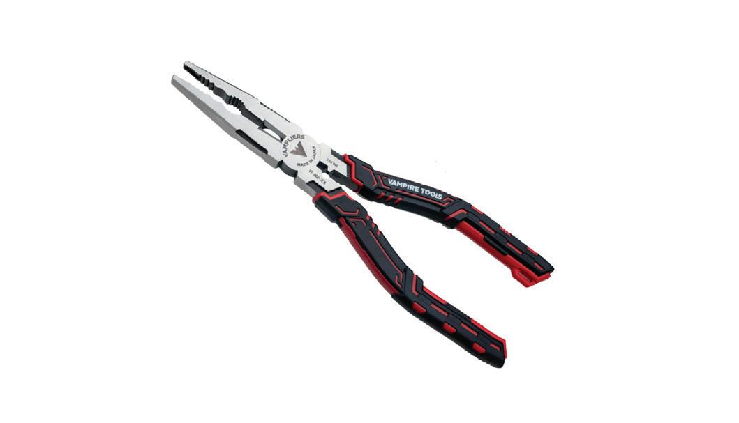
The Vampire Tools VAMPLIERS CAIMAN 7.5” Multi-Purpose Screw Extractor Long Nose Pliers, VT-002-7LN, are designed to be a versatile, all-in-one solution for professionals. Combining screw extraction, crimping, cutting, and wire work, its precision jaws remove stripped or rusted screws and handle hard-to-reach fasteners, accommodating 2-5.5mm heads. Intermeshed teeth provide superior grip, according to the company, for twisting and bending wires, while the built-in crimper fits 1.25-2.5mm wires. Crafted from high-carbon Japanese steel (HRC60 ±2) with ergonomic TPR handles.
FENDERBENDER.COM/55372071
The Carlyle Tools Magnetic Tool Tray features a magnetic socket extension holder with a non-marring design to protect surfaces while keeping sockets organized and within reach. Its low-profile, flexible construction bends easily to fit in tight spots or curls up for compact storage. Designed to magnetically cling to toolboxes, lifts, and even curved or ferrous surfaces. Available in a 4” or 10” option.
FENDERBENDER.COM/55374571
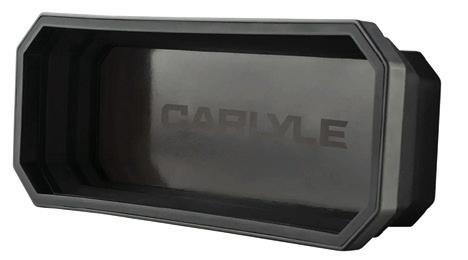
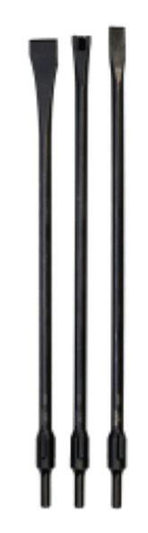
The Mayhew Tools 3-pc Long Non-Turning Pneumatic Set, No. 32215, is engineered with an extended length to provide professionals with easy access to hard-to-reach areas. Each tool in the set features four grooves that lock securely into the retaining balls of a quick-release chuck, This design ensures maximum stability and a firm hold, allowing the tool to move back and forth on a single plane with the c-axis locked in place. Crafted from high strength steel alloy, this set features a black oxide finish for corrosion resistance.
FENDERBENDER.COM/55374564
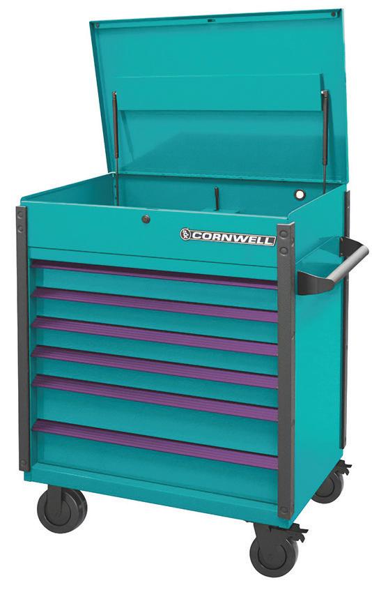
The Cornwell Quality Tools 40” ARCA Tool Cart - Riptide, Nos. CTSASF406URT and CTSASFP405ORT, is offered in five- and six-drawer configurations, featuring a cage frame construction with fully enclosed side panels. It rides on four 6” by 2” heavy duty polyurethane crowned casters. Drawers utilize Accuride ballbearing slides with the TLC+ retention system and include non-slip liners and full-length pulls with decorative end caps. The till includes an embossed floor mat with openings for long tool storage. A tubular keyed lock secures contents, and the cart is powder-coated inside and out.
FENDERBENDER.COM /55374583
The Cal-Van Tools Extra Long Ratcheting Chain Wrench, No. 87000CV, combines a heavy duty 24” chain to grip nearly any shape, round, square, or otherwise. Features a 20” chrome-plated, knurled handle for additional leverage to loosen stubborn items in tight working spaces. Allows the user to quickly adjust for another turn without removing the tool or resetting the chain.
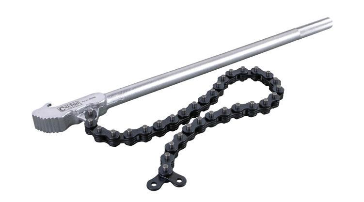
FENDERBENDER.COM /55374565