


A dverti $ er Component manufaCturing Serving the Structural Building componentS induStry S The

Anna Stamm – Advertiser Forum: Rationalizing Our Habits
Joe Kannapell: The Development of the Truss Plate, Part IX: The Case of the Century
Tony McCoy – Spida Machinery: Spida Machinery’s Automated Apollo Saw—Evolution
Todd Drummond Consulting, LLC: A Message of Caution to New Component Manufacturers
Glenn Traylor: Should We Consider “Delivery” Load Cases?
Edmond Lim, P.Eng. –LimTek Solutions: A Tailor-Made Lean Lumber Picking Solution
Rob Bellian – Vekta: Backwards Compatibility: Unlocking the Full Potential of Your Investment
65
72 78 84
Carl Villella – Acceptance Leasing: How High Will Interest Rates Go?
Thomas McAnally – The JobLine: Building Your Own Home – Part II: One Home, Two Loans
Geordie Secord – Design Connections: The Designer Shortage—Where Can We Find Them
David Conner – Timber Products Insp: Truss Design Value Comparison Tables
Tuomo Poutanen: Glued Roof Trusses
MiTek Staff: Bracing on Truss Design Drawings
Simpson Strong-Tie Staff: How to Accommodate Misplaced Shearwall Anchorage
Joe Kannapell – The Last Word LBMs and
$ er Component manufaCturing Serving the Structural Building componentS induStry S The Inside Articles 6 10 17 25 35 47
A dverti
54
the
Component Business
94 104 108 136


BEFORE YOU MAKE THE BIG LEAP INTO AUTOMATION, IT IS VITAL TO EVALUATE YOUR CURRENT FACILITY TO ENSURE YOUR MONEY IS WELL SPENT. 4W Tomasz Cwik Automation & Robotics Specialist tomasz@4wardconsult.com 313.513.1630 Mike Ruede Jr. Automation & Robotics Specialist mike@4wardconsult.com 951.297.0085 CONNECT WITH OUR EXPERTS 4WARDSOLUTIONSGROUP.COM WHAT WOULD -AUTOMATIONLOOK LIKE IN YOUR FACILITY? PLAN SMARTER WITH A 4WARD AUTOMATION ASSESSMENT.
Publisher Thomas McAnally twm@componentadvertiser.org
Editor Anna L. Stamm 800-289-5627 x 3 anna@componentadvertiser.org
Distributed FREE Via e-mail subscription Download PDF or Read on line at www.componentadvertiser.com
News of Interest and Advertising inquiries can be submitted to: anna@componentadvertiser.org An Open Forum for many sources. Deadline 20th of each month. Articles, Trade Names, and Logos are the property of their respective owner or creator unless otherwise noted
Disclaimer: We reserve the right to refuse any advertisement or material that we deem not in the interest of the industry or the Advertiser. Permission to use content is the responsibility of the contributor including permissions to use any likeness of persons.
The Advertiser is provided “As Is” including typographical errors, omissions, and mistakes both intentional and unintentional.
Advertisers Sections 4Ward Solutions Group Acceptance Leasing & Financing Acer, Inc All Points Technical Alpine Clark Industries, Inc. Eagle Metal Products Eide Integrated Systems, LLC | ProCut, LLC EstiFrame Technologies Fitzgerald Group HOLTEC USA Hundegger USA LimTek Solutions MiTek Panels Plus ROGworx Automation Simpson Strong-Tie Spida USA The Hain Company TheJobLine Timber Products Inspection Todd Drummond Consulting, LLC Triad | RUVO | Merrick Machine Vekta Automation Wasserman & Associates Wolf X Machina Wood Tech Systems ........................................................................ 4,115 .................................................. 13,51,65 ............................................................................................ 42,110 ............................................................................ 19,31 .................................................................................................. 22,74 ............................................................................. 8,60 .......................................................................... 14,68 .................................... 32,62 ................................................................... 38,118 .................................................................................. 19,59 ...................................................................................... 2,66 .......................................................................... 9,33,41,93 ......................................................................... 30,46,47 ........................................................................................ 12,104,135 .......................................................................................... 64,77 ........................................................................ 44,45 ............................................................... 20,58,108,126 ............................................................................ 16,17,52,76,82 ............................................................... 9,13,39,93,106 ................................................................. 33,51,59,61,72,78,119 .......................................................... 34,84,112 ...................................................... 24,25 ............................................... 81,116,138 ........................................................................... 28,54,56 ......................... 7,15,31,43,61,63,67,69,71,77,80, 83,92,101,107,111,117 ................................................................................ 57,63 .................................... 15,19,21,23,29,31,40,41,50,53, 57,63,67,69,70,71,73,75,77,102,111,117 New & Used Equipment Saws Truss Equipment Panel Equipment Trucks & Trailers Misc. Equipment Modular Manufacturing Door | Stair | Window Equipment Giggles Safety First Calendar of Events Industry News Directory Hiring Zone Published Monthly
Believe it at your own risk! 30,55,64,72
Component Manufacturing Advertiser The Advertiser 411 Walnut Street
Cove Springs, FL. 32043 no reproduction in whole or in part without permission from the component manufacturing advertiser Archive Copies Available On Line www.componentadvertiser.com Inside A dverti
er Component manufaCturing Serving the Structural Building componentS induStry S The ................................................................................................ 7 .............................................................................60 .............................................................................64 ............................................................................83 ...........................................................................83 ...............................................................107 ................................................111 .................................................................................111 ............................................................................................113 ...............................................................................114 .........................................................................................122 .................................................................................................132 ............................................................................................134
Copyright 2008-2023
#12250 Green
$
Advertiser F Forum

Rationalizing Our Habits
Anna L. Stamm Director of Communications and Marketing Component Manufacturing Advertiser.

To some degree, we are all creatures of habit. We all have routines that we repeat on a regular basis. What differs between us is how many routines, how much repetition, and how much they do or don’t matter to us. So occasionally, it’s good to step back and evaluate whether our habits are really helping us.
Habits with a Good Reason
Sometimes, our habits evolve for reasons that are justifiable, even though to an outsider it looks silly. For example, how many of us have ever had a “favorite pump” at the gas station? I don’t have one now, because here in Oklahoma there is practically a gas station on every corner (attributable to cheap gas and a preponderance of pick-up trucks). In Wisconsin, however, I always went to one particular pump at a Shell station. Why? Because it was the second-most convenient pump for pulling into the station from the main road and exiting the station on the side road. Why not use the “most” convenient pump? Because the nozzle dripped! People may have thought it was a kooky habit, but I had my reasons.

Habits Based on Comfort
So, what if I hadn’t had those two very good reasons to visit that particular pump – would it have been a crazy habit? Suppose the traffic patterns played no role, and suppose that all of the pumps were in perfect working order. In that case, would my idiosyncratic repetition been reasonable? When do we know if our comfort level in doing something has risen to the status of being a good reason?
Staying Open to the Possibilities
At work and at home, we have hundreds of small and large habits that have developed over the years. Sometimes the need for our habits is obvious. But sometimes, the rationale for our habits has faded and we’re left with routines that may or may not be efficient, effective, or even relevant. In that case, we may not replace an old habit with a new approach, but it’s still worthwhile to consider the alternatives.
PHONE: 800-289-5627 FAX: 800-524-4982 Read/Subscribe online at www.componentadvertiser.com Don’t Forget! You Saw it in the Adverti$$er April 2023 #15285 Page #6 A dverti $ er Component manufaCturing m The
Monet DeSauw FWA 500 Floor Web Cutter
• Push Button Powered Blade Angulations
• Single Push Button Setting for 2 Blades per Side
• Electronic Digital Readouts
• Backup Mechanical Indicators
• Cuts 4 Angle Webs, Cantilever Webs (2 piece webs) & Square Blocks
• Magazine Lumber Feed for 3x2, 4x2 and 6x2 Lumber 12 1/2” to 48 1/2” Length Capacity (7” Minimum on Square Blocks)
• 60 Pieces per Minute
• (4) Internal 16” Blades & (1) External 16” Cut-Off Blade
• Pneumatic Blade Brake on External Blade
• Dust Hoods
• Belt Waste Conveyor (under saw)
• Add $4,200 for 12’ Incline Waste Conveyor (adjacent to saw)


• Add $1,900 for Extra Set of Blades
• 480 Volt / 3 Phase FOBMO
Call For Pricing
Monet DeSauw DeRobo
Linear Saw
• Automated (Truss Design Software Download) or SemiAutomated (Touch Screen Entry) Operation
• All Movements are Computer & PLC Controlled
• Comprehensive Setup Screens Display Each Piece with Setup
Data
• 22” x 40 Tooth Blade on PAE Cut 1 or 2 Boards up to 20’ (2 Second Plunge Cut)
• Cut Chords, Webs, Rafters, Wedges & Stair Stringers
• Cut Long Scarfs by MultiPlunging
• Servo Positioning on Infeed, Angle & Outfeed Pusher
• Over Travel Protection
• Ink Jet Printer
• Lumber Optimization Program
• Belt Waste Conveyor
• 480 Volt / 3 Phase / 60 Amp
• Includes 5 Day Onsite Installation & Training
• Optional Monet DeSauw Live Deck, Bunk Feeder & Incline Belt Waste Conveyor FOB MO Call For Pricing

Monet DeSauw DeSawyer
2000 Automated Saw
• Touch Screen User Interface with Backup Mechanical Controls
• 3 Operating Modes: Auto, SemiAuto & Manual
• All 20 Axes of Movements are Computer & PLC Controlled
• Comprehensive Setup Screens Display Each Piece with Setup Data
• Anti-Collision & Optimizing Programming

• Auto Calibration Productivity & Time Tracking
• Maintenance Diagnostics
• Variable Speed Conveyor (0-50 Flights per Minute)with Powered Hold Downs
• (1) 30” x 80 Tooth Blade (27 3/4”
Scarf on PAE)
• (4) 16” x 40 Tooth Blades (13 1/2”
Scarf on Centerline)
• Pneumatic Blade Brakes on all 5 Blades
• 16 1/2” to 20’ Length Capacity (11” Minimum on Square End Blocks)
• Vibrating Waste Conveyor Under Saw
• 480 Volt / 3 Phase
• Includes 4 Day Onsite Installation & Training
• Add $2,900 for Extra Set of Blades
• Optional Live Deck, Label Printer, Ink Jet Printer, Catcher Display & Incline Belt Waste Conveyor.
Call For Pricing FOB MO
Buy Factory Direct From Wasserman & Associates at the same price as the Manufacturer, and get the added support and care you need to be up and running FAST! WE’LL EVEN HELP SELL YOUR USED EQUIPMENT TOO!
PHONE: 800-289-5627 FAX: 800-524-4982 Read/Subscribe online at www.componentadvertiser.com Don’t Forget! You Saw it in the Adverti$$er April 2023 #15285 Page #7 A dverti $ er Component manufaCturing m The 800-382-0329 | www.wasserman-associates.com
NEW! NEW! NEW! NEW SAWS!
CONSIDERING EQUIPMENT? CONSIDER CLARK.
EZ-SET AUTO JIGGING EXCLUSIVE & PATENTED DESIGN
Automatic Truss Jigging System to drastically reduce setup times. Allows for 100% embedment on the table, with top & bottom chord pucks in the same slot. TopSider or standard configurations available for conventional kick-leg, walk-thru, or our new trackless 8' and 10' continuous table systems. Systems for other roller & hydraulic gantries are coming soon. Available in new machine installations or for retro-fitting your existing table. The TopSider is exclusively applicable for “kick or flip leg” style truss presses such as the Tri-Axis & Lumbermater®


FEATURES / APPLICATIONS
• Capable of 100% On-Table Nail Plate Embedment
• Two Pucks Per Slot
• 24", 26", and/or 30" Spacing
• Compatible with all current major design software
• Multiple Simultaneous Layouts
Lumbermater® is a registered trademark of Illinois Tool Works, Inc., or ITW.
EQUIPMENT FOR TRUSS & COMPONENT MANUFACTURERS WWW.CLARK-IND.COM / GENERAL@CLARK-IND.COM LOCAL 417-235-7182 • US TOLL FREE 800-743-9737
2Seconds
That'sallthetimeittakes
todrillstudsforrunningRomexorotherelectricalwireinthewallpanels
Motor: HeavyDuty5HP-3phase-220vor440v(Pleasespecifywhenordering)
MotorcarriagebearingandspindleassemblymountedonBlanchardgroundsteelplate
LinealmotionishardenedandgroundVbearingsandrails

BlockSizes: 2x4through2x12infiniteheightsettingtocenter
AirSupply: 100psi10CFM

Drills: 2wing3/4'”CarbideTippedcanaccommodatesmallerorlarger
Spindles: AlloySteelpolishedandgroundprecisionshafting
Frame: 2"SteelWithPowderCoatFinish
Covers: 10Gauge(1/8"Thick)Aluminumremovable

Dimensions: Height-60inches,Width-33inches,Depth-33inches
Shippingweight: 750lbs.-(Includingcrate)
MADEINAMERICABYAMERICANS
PHONE: 800-289-5627 FAX: 800-524-4982 Read/Subscribe online at www.componentadvertiser.com Don’t Forget! You Saw it in the Adverti$$er April 2023 #15285 Page #9 A dverti $ er Component manufaCturing m The 916-508-3558• ww w.thehaincompany.com SeetheStudDrillerinaction! Goto https://youtu.be/AnODX5vPesE forademonstration
Work Smar ter
The Development of the Truss Plate, Part IX: The Case of the Century
By Joe Kannapell
Among our industry’s unsung heroes, Walter Moehlenpah takes a close second place behind Cal Jureit. Both built pivotal, pioneering businesses, Jureit through his truss plate and Moehlenpah through his truss machine. Yet Jureit was bound to have the upper hand, as he was the truss plate’s inventor and owner of the patent, and he had already put together a nationwide franchise and had won lawsuits against Bill Black’s truss plate twice. Now Moehlenpah had the audacity to challenge Jureit with a very similar plate, and the outcome of this challenge would change the landscape of the truss industry permanently.


Moehlenpah was as fine a mechanical engineer as Jureit was a structural engineer, but most crucially, he attracted some of the finest talent. One of the first was a McDonnell Aircraft engineer, George Pallme, who designed the most prolific truss machine, the Mono Press, with the skills he had honed working on the most prolific fighter-bomber, the F-4 Phantom. Not long after, Moehlenpah hired William Webster as his attorney, who would later serve as Director of both the FBI and the CIA. Recently, Director Webster recounted his fond memories of working with Moehlenpah in the days before his ascent to the highest ranks in government. But Moehlenpah’s most consequential hire was Stuart Senniger, his patent attorney and ultimate defense counsel. Senniger was a Principal of a St. Louis specialty firm, Senniger, Powers and Leavitt, and was a celebrated patent litigator.
In August 1960, Moehlenpah applied for a patent on a connector similar to the Atkins plate and began marketing it. (For details on the Atkins plate, see The Development of the Truss Plate, Part VIII: Patent Skirmishes.) By May 1961, Jureit became aware of this and brought suit. Because patent law derives from a federal statute, infringement claims are adjudicated in the federal court with jurisdiction over the location of the alleged offense. In the present case, the District Court in the Eastern District of Missouri would hear the case in St. Louis, about 4 miles from Hydro-Air’s headquarters. Coincidentally, a few years later, William Webster would preside over this court.
Jureit was represented by two eminently qualified firms with distinguished principals. His counsel in drafting the patent and litigating it was D.C.-based Robert E. LeBlanc, who was said to be one of the top litigation patent attorneys in the United States. His local counsel was Kingsland et. al., whose senior partner had served as the head of the U.S. Patent Office. Each of these participating attorneys was registered with the U.S. Patent Office as having demonstrated their

PHONE: 800-289-5627 FAX: 800-524-4982 Read/Subscribe online at www.componentadvertiser.com Don’t Forget! You Saw it in the Adverti$$er April 2023 #15285 Page #10 A dverti $ er Component manufaCturing m The Continued next page
qualifications to practice patent law, a highly specialized field requiring mastery of Patent Office practice, and usually necessitating both engineering and law degrees. Obviously, these high-level attorneys earned generous retainers, rendering patent work a very expensive business. In turn, the patents often were worth the cost and effort.
The patent on Xerography, for example, enabled Xerox to discourage competitive offerings, facilitated recovery of development costs, and encouraged development of new products. And the first Xerox machines proved themselves in the truss business by lowering the cost of providing multiple sets of drawings and reducing engineering turnaround time. The same could be said about Jureit’s Gang-Nail plate in reducing the cost of building roof trusses and improving delivery times. Both inventions quickly proved themselves, attracting droves of customers. Yet their obvious success, and the high prices they commanded, also made them worth challenging.
The challenge mounted by Moehlenpah could make or break his business, and it was gutsy, selling a plate that was very similar to one that had been twice forced off the market. Likewise, the defense mounted by Jureit was crucial in assuring that he would continue to harvest the fruits of his invention and forestall pricebusting competition. With all that was at stake, and the legal horsepower lined up on opposing sides, this trial would prove to be the case of the century for the truss business.

Senniger put together a formidable two-pronged attack on the validity of Jureit’s patent. First, Senniger used a courtroom demonstration acted out by his expert witness, Washington University’s Dean of Engineering, that proved the Hydro-Air tooth was stronger than the Gang-Nail tooth. Second, he found a British patent from 1893 and a French patent from 1947 that constituted “prior art,” which in the words of the judge:
“… it certainly does not take inventive genius to make joints with plates differing from the French connector plates only in that the Jureit plates have nails struck out from the plate instead of being welded to the plate.”
Accomplishing what the verdicts in the previous lawsuits had not, this decision effectively invalidated the Jureit patent and allowed Moehlenpah to continue unimpeded. Although Jureit appealed the decision, the appellate court found no reason to overturn it. From this point forward, the connector plate industry was “open for business.”
Next Month: The Housing Market Takes Off
Since 1970, Joe Kannapell has worked as programmer, Chief Engineer, Marketing Manager, and Sales VP for MiTek, plus 7 years at truss plants, retiring at the end of 2020.
PHONE: 800-289-5627 FAX: 800-524-4982 Read/Subscribe online at www.componentadvertiser.com Don’t Forget! You Saw it in the Adverti$$er April 2023 #15285 Page #11 A dverti $ er Component manufaCturing m The
Maximize production with integrated off-site technologies


Increase the productivity of your component manufacturing operation with the latest off-site solutions and prefabrication technology. From software that manages many aspects of your business to machinery that maximizes your output, MiTek is committed to the growth of your business and the industry. Together, we’re unlocking the power of off-site construction. Together, we are innovating to meet the needs of an evolving market.
Are you ready to maximize productivity of your operation? Talk to a MiTek Representative to get started.
MII.COM/CM
Used Razer S5 Linear Saw
S5 Razer saw modules configured for either left-to-right cutting and/or “Z” shaped layout. AIT auto infeed tables. Vekta user interface software complete with the full version of the optimization algorithms. Stack cutting and side by side cutting
Contact for Pricing
Eide Integrated Systems, LLC 612-521-9193
www.eidemachinery.com

Safety Speed Manufacturing Model

7400 XL Panel Saw
Safety Speed Manufacturing, model 7400 XL*, vertical panel saw, 3 HP induction motor, 64 inch crosscut, 2 1/8" maximum thickness, accuracy within 0.005 inches, 13 foot long welded steel frame with integrated stand and linear V-guides, enclosed counterweight system, adjustable vertical and horizontal rules. Quick changes from vertical to horizontal cutting. Includes machined aluminum material rollers, hold down bar, wheels, quick stop gauges and material hold downs. Dust collection ready. Options available include digital readouts for vertical cuts, automated length measuring, laser guide, stop bar, vacuum and midway fence. 208-230/460 volt, 3 phase electrical (208-230 single phase, 2 HP power optional +$100.00).

$13,149 Base, FOB MN. Wood Tech Systems 765-751-9990
www.woodtechsystems.com

HSF Hain Systems Framer

Electrical Supply: 110 VAC
Motor: 1/4 HP, 110 VAC, Linear Actuator
Highly Accurate: +/- .010 Inches
Stop Rail: 2 x 4 x 1/4 Aluminum Extrusion

The Hain Systems Framer (HSF) will help you build square and accurate wall panels for residential or commercial construction applications. It will help you cut building costs by saving time and improving your quality. It’s a reliable, efficient and proven system that features a ruggedly simple design. The HSF is based on a proven design with over 20 years of actual production use and maintenance experience. It comes fully assembled and is designed for portable job site framing or in-plant permanent installation. The table has many optional attachments and will support Mylar Tape wall layout or any other type of layout. The optional gun rails can also be retro-fit to any table.
Stops: Jig Bored Steel
Stop Blocks: Machine Billet Aluminum
Details:
Internal Components: Hardened, Ground and Polished Steel and Billet Aluminum
Dimensions:
Length: 5 feet (60”) to 60 feet (720”)
Table Construction: Thick-wall Structural Steel Tubing, Jig Welded for Accuracy
Height: 12 inches
Depth: 12 inches
Air Supply: 90 psi (10 CFM Air Flow Recommended)
Electrical Supply: 120 VAC
Powder Coat: Industrial Gray
Dimensions: Height: 43”
Length: 16’ or 20’
Width: Adjustable 8’ to 10’ or 8’ to 12’
Shipping Weight: 3000 lbs
If you are looking for the fastest, most consistent way to measure and cut your product, then the Hain Measuring System (MEA) is your answer. The MEA changes from one length t any length instantly, up to 60’, without changing the operator’s position on the line. It is also highly accurate (+/- .010) and quickly moves from one length to the next in seconds. The MEA is designed for quick and easy setup and is simple to use. Even a first time user will be productive with little or no training required. It can adapt to any saw and can be mounted to any surface so that you can integrate the MEA with your existing setup. The MEA is versatile allowing “left” or “right” handed operation and measurement in “feet and inches” or “inches” depending on your preference. The MEA is also available in a “Skid Mounted” version.
theHAINCOMPANY

6125 Enterprise Drive, Unit 9 | Diamond Springs, CA 95619 530.295.8068 | sales@thehaincompany.com
PHONE: 800-289-5627 FAX: 800-524-4982 Read/Subscribe online at www.componentadvertiser.com Don’t Forget! You Saw it in the Adverti$$er April 2023 #15285 Page #13 A dverti $ er Component manufaCturing m The SAWS
NEW! A dverti$er Component manufaCturing S erving the S tructural B uilding c omponent S i ndu S try The
Start smarter... Grow faster... Achieve more... cvillella@acceptlease.com | www.acceptlease.com 894 Beaver Grade Road, Suite #304 - Moon Township, PA. 15108 Phone: 412-262-3225 Fax: 412-262-1154 Keep More of Your CASH Eliminate Yearly Financial Reporting Low Fees Fixed Payment Programs No Additional Collateral Now offering short term Working Capital Loans “Serving the Component Industry Since 1996” Start smarter... Grow faster... Achieve more...
Electrical Supply: 110 VAC Motor: 1/4 HP, 110 VAC, Linear Actuator Highly Accurate: +/- .010 Inches Stop Rail: 2 x 4 x 1/4 Aluminum Extrusion Stops: Jig Bored Steel Stop Blocks: Machine Billet Aluminum Internal Components: Hardened, Ground and Polished Steel and Billet Aluminum Dimensions: Length: 5 feet (60”) to 60 feet (720”) Height: 12 inches Depth: 12 inches If you are looking for the fastest, most consistent way to measure and cut your product, then the Hain Measuring System (MEA) is your answer. The MEA changes from one length t any length instantly, up to 60’, without changing the operator’s position on the line. It is also highly accurate (+/- .010) and quickly moves from one length to the next in seconds. The MEA is designed for quick and easy setup and is simple to use. Even a first time user will be productive with little or no training required. It can adapt to any saw and can be mounted to any surface so that you can integrate the MEA with your existing
Design and build faster than ever. Learn

From plans, to walls, to panels, and everything above. Introducing a new level of design tools, built from the ground up.

more a t EagleMetal.com
Equipment Wanted!
Saws
• Automated Component & Linear Saws (2010 & Newer)
• Monet DeSauw or TimberMill
Manual Component Saws
• Floor Web Saws
• Spida (Apollo) Saws with Truss Automation
• Bunk Cutters
Truss Equipment
• Roller Gantry & Hydraulic Press Systems
• Finish Rollers
• Truss Stackers
• Floor Truss Machines
• Lumber Splicers
• Jack Tables
• C-Clamp Presses
Trucks & Trailers
• Stretch Roll-Off Trailers
• Go oseneck Roll-Off Trailers

Modular Equipment
• Pacific Automation or MiTek Mobile Home Press
Contact Wasserman & Associates for a Fair Market Value Assessment of your Used Equipment Operational, Needs Work, and Parts Only equipment will be considered!
800-382-0329 | www.wasserman-associates.com
Terminailer XP
Price: $224,000
FOB: MN
Don’t just do it, nail it. It’s a brand new day in wall-panel production, with a whole new way of doing things better.
Terminailer®, a revolutionary, event-driven, nailing machine that completely defies any preconceived notions about sub-component assembly.
1988 Clary Master 5-Blade Component Saw
1988 Clary Master, 5-blade component saw, rebuilt by seller in 2013. Cuts dimensional lumber from 1′-6″ at 90/90, to 20 ft lengths, 2×2″ through 2×12″. Includes analog displays for angles and length, powered angulation and length, shaker pan undersaw waste conveyor, (1) 32″ blade, (1) 22″ blade & (2) 18″ blades & (1) 16″ blade. Cuts 4-angle floor webs at 3′-0″ minimum. In working order when decommissioned in October of 2022. Includes belt incline, schematic drawing and all available spare blades. 480 volt, 3 phase electrical required.
$8,497 FOB ID
Wood Tech Systems

765-751-9990
www.woodtechsystems.com


Whirlwind Model 1000 Cut-Off Saw
• 5 HP Motor with 14" Blade
• 2 3/16" x 8 1/4" Capacity
• Pneumatic Blade Guard/Lumber Clamp
• Foot Pedal Control
• Dust Collection Outlet
• 460 Volt / 3 Phase
• 1 Left Hand & 1 Right Hand Model
Available $3,500 Each FOB NC
Wasserman & Associates 800-382-0329
www.wasserman-associates.com
Terminailer all but shatters the stereotypical myth that subcomponent equipment is essentially peripheral – unimportant. And it does so by quickly and accurately driving far more framing nails in your wall panel jobs than ever before. Whether in your shop or in the field, one operator sets the pace for production and quality. And that reduces labor costs and other aspects of overhead.
Terminailer is an event-driven, sub-component assembler that will quickly and accurately drive 30% to 70% of the framing nails in any wall panel job. In your shop or in the field, one operator sets the pace for production and quality. The Terminailer functions independent of design software, requires zero set-up time when switching between any configuration, and requires no special operator training.
The Terminailer is easy to move around the shop so it’s location can evolve as your shop evolves. With all of the nailing occurring in the closed main chamber, nail injuries and nail location miss-fires are eliminated, making your plant that much safer.

With nearly ten years of development from people that know machinery it is assembled to exacting standards, well supported, and it is easily maintained with shelf-item parts. Terminailer: vetted, tested, and ready to drive maximum productivity for you. Be sure to check out our videos below for a quick review of this revolutionary machine!

PHONE: 800-289-5627 FAX: 800-524-4982 Read/Subscribe online at www.componentadvertiser.com Don’t Forget! You Saw it in the Adverti$$er April 2023 #15285 Page #15 A dverti$er Component manufaCturing S erving the S tructural B uilding c omponent S i ndu S try The 765-751-9990 www.woodtechsystems.com NEW!
SAWS


Spida Machinery’s Automated Apollo Saw—Evolution
By Tony McCoy
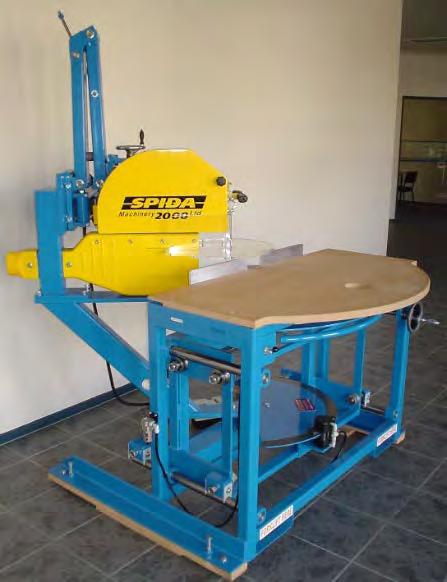
Back in the fall of 2001, when I was a component manufacturer, Bevan Lines, Director of Spida Machinery, came to a sales meeting in Southaven, MS, to introduce our sales team to the first automated pull saw in the truss industry — the Computerized Spida Saw, better known as the CSS. The CSS is the great-great-great grandfather of today’s incredible Apollo Saw. Bevan showed our sales team a video of the CSS in action and explained its many operational features and benefits. After listening to Bevan’s presentation and seeing the abilities of the CSS in the video, I knew this saw would have a big impact in the truss industry. After this most important meeting, my truss company worked together with Spida Machinery and in the following 12–18 months we supplied more than a dozen CSS saws to our various truss plants.


The CSS was one of the most reliable and durable saws on the market then, and now the Automated Apollo Saw is carrying on this tradition.
Just as big linear saws and component saws will always be a staple in the industry, so too is the Automated Apollo Saw — it complements any plant situation, large or small. Its multiple uses means it can cut roof truss members, wall panel parts, and floor truss members. For smaller plants, this saw is a perfect addition as a primary production saw or a supplemental saw cutting odd pieces. The Automated Apollo Saw works with all plate supplier software, including wall panel software.
The Apollo can cut most truss members, including short wedges and sliders, in a flat 2x4 orientation, chords and webs single or double stacked, floor truss webs in a 4x2 orientation, and even material for wall panels — and then it can label the parts with an optional ink jet printer. The Automated Apollo Saw can be set up in a left-to-right or right-to-left
PHONE: 800-289-5627 FAX: 800-524-4982 Read/Subscribe online at www.componentadvertiser.com Don’t Forget! You Saw it in the Adverti$$er April 2023 #15285 Page #17 A dverti $ er Component manufaCturing m The Continued next page
CXM Spida Saw at BCMC 2005
BCMC 2007
orientation for the best material flow in your facility. The saw has a moving stop/trolley that positions truss members for precision centerline or off-center cuts. Whether cutting centerline webs or offset scissor bottom chords, this saw takes away all of the guess-work. It does not make mistakes, so recuts are never a problem. Training is straight-forward, and the software UI is intuitive and easy to learn. The Automated Apollo Saw will be the most reliable piece of equipment in your operation. To date, I have never heard of an Automated Apollo Saw calling in sick!!!

The Automated Apollo Saw can be tied directly into your network for easy uploading of jobs, or you can use a USB thumb drive to transfer jobs. In the old days we called that network “sneaker-net”. I’ll explain that in another article, LOL!
Even today, I still see old CSS and Mango saws in manufacturing facilities around the country. Knowing how reliable the Spida CSS was, when developing the Apollo Saw, Spida knew we had to plan for the future. Over the years, we have developed and continue to offer upgrade kits for the older saws and we have a crack service team ready to complete the upgrade process. Spida also carries an inventory of wearable parts such as blades, motor brakes, and drive belts.
Our cutting technology has continued to evolve since the first CSS was introduced to market. In fact, that Generation 1 CSS introduced in 1997 has been upgraded many more times, all the way to Generation 9 in 2021. And we’re not stopping now! We’ll keep making our products better, and we thank you for making us a top provider in this industry. The Apollo Saw has found worldwide success in the United States, Canada, South Africa, Australia, the Pacific Islands, and New Zealand.
When you’re ready to learn more, call your regional Spida Machinery Account Manager for more information and pricing. They can answer your questions and get you pricing information right away.
In next month’s article, we’ll take a closer look at the features that make the Automated Apollo Saw one of the best on the market today.

PHONE: 800-289-5627 FAX: 800-524-4982 Read/Subscribe online at www.componentadvertiser.com Don’t Forget! You Saw it in the Adverti$$er April 2023 #15285 Page #18 A dverti $ er Component manufaCturing m The
Not producing the results you need or want – getting conflicting info about what to do and the equipment and the systems you may need?


If
Also, don't let Financing Deals influence your best solution. FitzGroup can arrange – Zero down & No payments for 90 Days!

Please be assured that your investment with any of our selected partners will not cost one penny more with the Fitzgerald Group as your purchasing contact. In addition, you will receive the full advantage of our Partner Relationships and Services NOT offered elsewhere.

PHONE: 800-289-5627 FAX: 800-524-4982 Read/Subscribe online at www.componentadvertiser.com Don’t Forget! You Saw it in the Adverti$$er April 2023 #15285 Page #19 A dverti $ er Component manufaCturing m The REPRESENTATIVES 765-751-9990 www.woodtechsystems.com Monet FWA 500 Floor Web Saw New, Monet five-head, floor truss web saw, cuts 4-angle, 4x2 floor truss webs from 16 inches and 90-90 blocks from 12 inches to four foot long maximum length. Features 10-board magazine feed, powered, fixed-quadrant angulation, manual carriage standard, shaker-pan scrap conveyor with short incline conveyor and cut-off blade. Option for longer carriage length, single-sided setup (shown in pictures, but not standard), dust hood and horizontal scrap conveyor. 480 volt, 3 phase. Call for pricing, FOB MO. NEW!
excellent services
Fitzgerald Group, LLC a blending of
and products, with answers that work...!©
Before you Buy - Ask yourself –do I need a salesman or a guide?
you
an Independent Guide
your bottom-line results as the #1 priority,
Me.
want
that has
Call
If the salesman will do - we'll talk later...
www.FitzGroup.com A dverti$er Component manufaCturing S erving the S tructural B uilding c omponent S i ndu S try The Hiring Zone Building Component Industry's Job Board Employer to Candidate Direct Hiring No Recruiting Fees! Post your Opportunity... Candidates respond directly to you! For Additional Information Contact: twm@componentadvertiser.org or Call: 800-289-5627 x1 Visit our website: www.componentadvertiser.com/Hiring-Zone Your Solution for Lack of Technical Staff ● PlanSwift Lumber and Building Material Takeoffs ● Truss and Wall Panel Design Experienced Staff ● EWP Layouts and much more! Eliminate your lack of technical resources to grow sales and increase the clock speed of your company Dave.AllPoints@gmail.com • www.AllPoints.Tech The Gold Standard in Technical Support Teams
RFitzgerald@FitzGroup.com 719.528.5445
Leverage the power of a strong network.
As a truss component manufacturer, you already know Simpson Strong-Tie as a reliable partner in the construction industry. But our connections go beyond the products we make. Our people can help reinforce your network of builders, engineers, contractors, equipment manufacturers and suppliers, strengthening your existing relationships. Also, our open-platform software is integrated with the most widely-used systems, and can be customized to work with the machinery you choose. Backed by our expert service and support, you’ve got all the resources to succeed.
Grow your business ecosystem with a well-connected partner. To learn more, visit our website at go.strongtie.com/componentsolutions or call (800) 999-5099.

© 2022 Simpson Strong-Tie Company Inc. TRUSS23PART
Simpson Strong-Tie® Building Technology | Software and Service for Smarter Business
USED ALS 276 LINEAR SAW SERVO PARTS & COMPUTER
• Used Servo Star CR10251 (2 Available) -$1,100 Each
• Used Servo Star CR06251 (2 Available) - $1,100 Each

• Used ALS Windows XP Computer - $1,500

• Used parts were removed in "working condition" from the ALS 276 during a saw upgrade FOB AL Wasserman & Associates 800-382-0329 www.wasserman-associates.com
2002 Koskovich Auto Omni component saw, 5-blade automated saw includes [3] 20 inch blades, [1] 30 inch blade, [1] 12 inch blade and shaker waste conveyor with factory side pans. Fully automated setup with full power length and all axis angulation, single-sided setup from operator console, 2×3 through 2×12 and 4×2, 20’ to 9” @ 90°/90°, Exair cabinet coolers, remote monitor, no spares. In operation until Aug. ’21. 208/240/480 volt, 3 phase, 100 Amp saw electrical required. 120 volt, 1 phase PC electrical required.
$13,970 NOW $9,997 FOB OH Wood Tech Systems

765-751-9990
www.woodtechsystems.com

Safety Speed Cut Model 7000 Panel Saw
Safety Speed Manufacturing model 7000, vertical panel saw, 3 HP induction motor, 64 inch crosscut, 2 inch maximum thickness, accuracy within 1/64th of an inch, 10 foot welded steel frame with integrated stand and linear V-guides, enclosed counterweight system, adjustable vertical and horizontal rules. Quick changes from vertical to horizontal cutting. Includes machined aluminum material rollers, hold down bar, wheels, quick stop gauges and material hold downs. Dust collection ready. Options available include lower frame extensions, digital readouts, laser guide, stop bar, vacuum and midway fence. 208-230/460 volt, 3 phase electrical (208-230 single phase, 2 HP power optional +$100.00). $9,332 Base, FOB MN.

New L-M Equipment
Verticut 2000 PET / Bunk Saw Station
The L-M Verticut 2000 is a true Precision End Trim (PET) saw that is capable of holding a 1/16th accuracy all day long. Made in the USA, the V2k comes equipped with a 15 HP 460/230 volt High-E three phase TEFC motor driving a Double ended Premium “Stellite” inlaid saw bar with a spring loaded chain tensioner and an automatic oiler to lubricate the .404 pitch custom profile semi chisel saw chain.
Rather than a single pivot-point, the saw assembly is mounted on a mandrel box that is guided by cam followers on a steel frame that is raised and lowered by a hydraulic cylinder. A console with the saw controls moves with the saw assembly along a track positioned using a manual “V” wheel geared drive or optional Hydraulic drive
The V2k is unlike other imported systems that are basically a Portable Yard Saw on a cutting rack with a best cutting accuracy of +/- 1/8″ (meaning up to ¼” accuracy variance between units of lumber). The V2k from L-M provides +/- 40 thousands, assuring consistent PET precision from unit to unit.
Another advantage L-M has over the competition is their commitment to personal service with unlimited phone assistance and technical help. Their team has traveled the country working on crosscut saws for many years and they know their equipment inside and out. L-M is a familyowned business that prides themselves in doing the job right and building long term relationship that is vital to their business: “Built to last as long as our customers since 1946”.
Price based on configuration FOB OR
765-751-9990
PHONE: 800-289-5627 FAX: 800-524-4982 Read/Subscribe online at www.componentadvertiser.com Don’t Forget! You Saw it in the Adverti$$er April 2023 #15285 Page #21 A dverti $ er Component manufaCturing m The SAWS 765-751-9990 www.woodtechsystems.com
NEW!
2002 Koskovich Auto Omni 5-Blade Component Saw
www.woodtechsystems.com
NEW!
IntelliVIEW Suite Manage. Design. Build.
The industry’s most powerful integrated component design, engineering, and management software for steel and wood-framed structures.
iCommand
Manage projects, customers, materials, pricing & inventory
iModel
Design truss layout & profiles


iDesign
Optimize material usage & engineer trusses

iPanel
Design wall layouts, panelize, bundle, break & stack
eShop
Maximize crew productivity & improve manufacturing efficiency
The IntelliVIEW Suite is a fully integrated software solution for the layout and design of a building’s rough framing elements—including roof and floor trusses, wall panels, solid sawn, EWP, sheathing and various ancillaries.


The IntelliVIEW Suite provides the industry’s most complete analysis of the design, cost information and bill of materials—promoting increased profits by reducing plate and lumber use.


Ask those who know. They’ll tell you about the people at Alpine who make a difference.

BUILD MORE. alpineITW.com | 800.521.9790
Call

Condition:


PHONE: 800-289-5627 FAX: 800-524-4982 Read/Subscribe online at www.componentadvertiser.com Don’t Forget! You Saw it in the Adverti$$er April 2023 #15285 Page #23 A dverti $ er Component manufaCturing m The 765-751-9990 www.woodtechsystems.com NEW!
New Monet DeSawyer 2000 Component Saw
for Pricing
New, Monet DeSawyer 2000, computerized, five-bladed component saw, sets up in 15 to 17 seconds, can run in manual mode, downloads projects from a network or manually using display screen controls. Features all powered movements, cuts from 15" 90/90 cuts to 20 foot length, 2 x 3" to 2 x 12" lumber depths and internal brakes are standard. Options include enhanced servo controls featuring autocalibration, catcher's display and either shaker or belt scrap conveyor and incline. 440 volt, 3 phase electrical. New
Location: MO
A Small Investment in Process Improvement with TDC has a Typical Payback of Less than Three Months

All Departments Sales, Design, Manufacturing, and Admin
• Proven and Practical Process Improvement with Lean Manufacturing based on Refined Industrial Engineering
• Increase Overall Productivity in all Departments Not Just Manufacturing
• Achieve Real Labor Reduction Costs Per Sales Dollar
• Improve Retention and Employee Management Practices
• Reduce Mistakes and Improve Quality

• Reduce 80% of the Repeated Questions asked Daily
• Decrease Training Time for New Employees
• Gain More of Your Valuable Time
Equipment and Building Design Recommendations
• Material flow, Equipment, and Building Design
• Unbiased with Absolutely No Referral Fees

• Pros/Cons and Expected Results
• Too Many Vendors have Suggested Costly Facilities and Equipment Choices with Significant Constraints that Could have been Avoided with TDC.
Time Standards Development










• Productivity Scheduling, Efficiencies Measurement, Productivity Incentive Programs, and Labor Cost Estimations
• Units based on Man Minutes, R.E., or S.U.
• See Article: A 1 Industries – Leader in Wood Truss Industries


Proper Productivity Incentive Programs for All Departments

• Based on Proven Industrial Engineering Practices

Brad Emmert—President Brazil, IN
“We recently had Drummond Consulting do a consultation at our Truss Plant. Todd’s services included plant efficiency, design efficiency, better organization, man minutes per truss type, and more. The value of Todd’s presentation and lean training was very beneficial to each of our team members. Just implementing a few of Todd’s suggestions will more than pay for his services in a short amount of time. The value and benefits of Drummond Consulting will continue our improvement in the market while urging him not to consult with our competitors!” Read Dozens of Client Testimonials (Link)
All Things Being Equal, a Gain of Three Net Profit Points is a Low Bar for TDC. A Gain of Only One Point Would Easily be 10x the TDC Investment for Most Companies
www.todd drummond.com todd@todd drummond.com (603) 748 1051
A Message of Caution to New Component Manufacturers


This message is for the new component manufacturers (CM) who have recently and will shortly be entering the component manufacturing industry for wood trusses or wall panels. First, welcome to the industry – it is very rewarding, but I must caution you about this new endeavor. It is not for the faint of heart, and it has complexities that are not so apparent. Here are some cautionary points concerning market conditions, vendor advisements, benchmarks, pricing, and process considerations to keep in mind as you move forward.
Did you know that the average net profit for a CM owned by LBMs is 5 to 10 points lower than that of independents? Yet, one former LBM CEO of 17 lumberyards with two CM plants stated that his two CM plants made up only 10% of their sales but then contributed about 30% of his net profits. He wished he had given the CM division far more focus and resources. The CM area or location is a manufacturing operation, not a retail yard. Please do not attempt to manage it as a typical LMB division. It takes a different mindset to manage day-to-day operations effectively. For more about this, see Truss and Wall Component Manufacturing for a Lumberyard – Pros and Cons.

Timing is everything, and even though now is not the best time to enter this industry, you must play the hand you are dealt. The coming years will present all CM operations with market conditions typical of this industry’s natural ups and downs. And currently, we are facing a downward trend that creates significant pressure on the profit margins of all CM operations, regardless if they are a new or existing operator.
Interest rates are going up to slow the economy. This rate hike will negatively affect every housing market, reducing the demand for new homes. Expect new and existing competition to fight harder to take from your sales. For more about this, see Don’t Be Blind to Simple Truths for the 2023 Build Season.

PHONE: 800-289-5627 FAX: 800-524-4982 Read/Subscribe online at www.componentadvertiser.com Don’t Forget! You Saw it in the Adverti$$er April 2023 #15285 Page #25 A dverti $ er Component manufaCturing m The
Continued next page
Todd Drummond
Lumber prices are dropping, and the peak pricing of the past few years is not coming back anytime soon. Cost markup is the most common method of pricing trusses and wall panels. As the cost of materials drops, this will significantly negatively affect your margins.
Every CM operation has spent tens of thousands, if not millions, to expand its manufacturing operation. All of this newly expanded manufacturing capacity will need to be filled to cover their capital expenses. Lead times for new orders will drop, and margins will fall dramatically from their peaks of the past two years. This leads me to talk about automation not being the cure-all many of you were promised by your equipment vendor.
The advisement many of you have been given by some equipment vendors may not have been the best for your situation. TDC has witnessed too many new and existing operations with vendor recommendation configurations with built-in manufacturing constraints that severely limit their total output and ability to expand as their manufacturing needs grow. These poor advisements can affect some or all of the different areas, such as material flow, equipment orientation, equipment recommendations, and building design, producing major constraint issues. The standard cure-all advisement is all too often about more automation to overcome the new CM’s manufacturing troubles, such as increasing labor costs. Yes, this significant labor shortage will continue for the coming decade, however, automation is not always the labor savoir that so many vendors claim it to be. For more about this, please see Labor Shortages Worse Than Most Understand and Automation is Not Going to Be the Cure-All Solution and Millions of Dollars for New Equipment and Building Investments are Being Wasted.

Yes, the wood components (wood trusses) are made of lumber, and typically lumber is priced and measured using board foot (BF). You will also find that BF is the most talked about and accepted unit of measurement in the CM industry. However, you will be at a competitive disadvantage if BF is used for scheduling, production efficiency measurement, and pricing for wood roof trusses. We can always learn things from industry leaders, whether we work with them directly or appreciate what they have accomplished. A perfect example comes from A-1 Industries and its commitment to using industrial engineering practices and work minutes. Although TDC has not performed consulting services for A-1 Industries, nor are they endorsing my services, their story reinforces a message that I cannot repeat enough – you must use reliable methods for basic unit measurement for pricing, scheduling, and shop efficiencies. For more about this, please see How One Wood Truss Industry Leader Uses Industrial Engineering Practices of Work Minutes to Excel.

PHONE: 800-289-5627 FAX: 800-524-4982 Read/Subscribe online at www.componentadvertiser.com Don’t Forget! You Saw it in the Adverti$$er April 2023 #15285 Page #26 A dverti $ er Component manufaCturing m The Continued next page
This is a statistic that is not well-known by many. Industrial engineers are all taught the following.

New manufacturing facility’s expected rate of efficiencies
• 1st year ~ 60% of standard (+/- 10%)
• 2nd year ~ 85% of standard (+/- 10%)
• 3rd year ~ company reaches normal efficiencies
No matter the automation your company has invested in or the experienced personnel you have employed, the vast majority of new operations fall into the same efficiency rate pattern. So many CMs are spending millions on new equipment and other capital investments, yet they are unwilling to spend a fraction of that investment on process improvement. Your new operation will waste tens of thousands, if not millions, on poor and outdated practices as you struggle to achieve the promised margins and profits you intended to make. Remember, the CM division is a manufacturing facility, not an LBM division. This means one should embrace proper lean manufacturing and industrial engineering best practices. Maybe, just maybe, your company should make a small investment in process improvement training embracing lean manufacturing industrial engineering practices.
TDC’s tailored solutions are for the client’s specific needs. Go beyond the typical software and equipment vendor recommendations for your operations and do what many have dared to do. Embrace the Drummond Method, and your company can experience cost savings, and net profit gains that usually take months or years can be accomplished in weeks or months, resulting in an average of 3 to 6-point net profit gains for CMs. All areas are addressed, not just the manufacturing. Please do not take my word for TDC’s services, though. Read the public testimonials many current and past clients with decades of expertise and experience have been willing to give: https://todd-drummond.com/testimonials/
Website: www.todd-drummond.com
Phone (USA): 603-748-1051
E-mail: todd@todd-drummond.com

Copyrights © 2023
PHONE: 800-289-5627 FAX: 800-524-4982 Read/Subscribe online at www.componentadvertiser.com Don’t Forget! You Saw it in the Adverti$$er April 2023 #15285 Page #27 A dverti $ er Component manufaCturing m The
VEKTA P3 Printer

The Vekta P3 printer is used to print position-dependent information onto the cut members in real time.
The VEKTA P3 PRINTER is designed specifically with the need of the Frame & Truss industry in mind. The Vekta P3 Printer delivers accurate, high-quality printing including all the information you want without slowing down your saw.
The Vekta P3 printer is by far and away the most capable print system for the timber frame and truss industry in the world!

Vekta worked with the intellectual property of HP to build a custom print system specifically for the industry. The Vekta P3 was designed from the ground up, allowing Vekta to continuously increase the amount, type and format of data that can be printed onto the cut timber components.


And with every new version of Vekta software, additional printing capability is being added to the system.

Is it time to AUTOMATE? Get in touch scan the QR code VEKTA USA 9555 James Ave S, Suite 203 Bloomington MN 55431 P: +1 763 566 0781 | E: info@vektausa.com
IT’S ONE THING IN LIFE TO MAKE THE CUT. IT’S ANOTHER TO MAKE IT BETTER.
Designed for high-volume floor truss web output with even greater safety, the Monet DeSauw FWA-500 AC (for “automated controls”) offers the very latest in operator-friendly saw technology. Perfect for manufacturers running floor trusses in large volumes with variable web design, the 500 AC features automation for all blades, including the fixed cut-off blade for minimal waste. And without any need to open the saw motor cabinets, except for periodic service, you’ll benefit from enhanced safety as well. You might say that with the fully automated FWA-500 AC, Monet DeSauw has set a new standard. Again. Contact us today to discuss how this exceptional machine can positively impact your production goals.
765-751-9990 www.woodtechsystems.com
Wood Tech Systems is a registered trade name of Wood Truss Systems, Inc.
One month after installing a Double Lumber PickLine to feed two TCT Linear Saws:


"We are getting 3,000 to 5,000 bdft more each saw, than we were getting before the install.


We have shut down one Cybersaw and one TCT chord saw.
This equals about 3 less people 10 hours, and 2 less forklifts 10 hours.
Overall, it is a major improvement to our operation. We hope to have the chance to run it two shifts to further accelerate the payback.”
Tom Hollinshed, Owner
LimTek Solu�ons Inc.


6021 Yonge St., Unit 1019
Toronto, ON M2M 3W2
Tel: (416) 888-4457
Edmond.Lim@LimTekSolutions.com
Edmond.Lim@LimTekSolu�ons.com
LimTekSolu�ons.com


New, DeRobo linear saw by Monet organizes "fill" boards to increase optimization of each board, can produce unlimited scarf cuts, cuts 1 or 2 boards at a time and cuts webs, chords, wedges, rafters and open-stair stringers. Works with all major connector plate manufacturer's software. Features include 22 inch blade, left-to-right feed direction standard, lumber push and pull grippers for more accuracy, ink marking on the 1 1/2" face of the incoming boards and small piece capture and delivery to the front of the saw for easy access. Infeed deck and bunk feed are shown as options only. 480 volt, 3phase. Call for pricing, FOB MO.


PHONE: 800-289-5627 FAX: 800-524-4982 Read/Subscribe online at www.componentadvertiser.com Don’t Forget! You Saw it in the Adverti$$er April 2023 #15285 Page #31 A dverti $ er Component manufaCturing m The 800-382-0329 | www.wasserman-associates.com 2000 Alpine AutoMill Automated Component Saw • Automated Setup via Download or SemiAutomated Setup via Touch Screen Input • 19 Axes of Automation • Five Blades cut 2x3 thru 2x12 from 18" to 20' • Waste & Incline Conveyor • Out of Service in 2018 • 480 Volt / 3 Phase • Price is in US Dollars $29,500 NOW $24,500 FOB ON Details Your Solution for Lack of Technical Staff ● PlanSwift Lumber and Building Material Takeoffs ● Truss and Wall Panel Design Experienced Staff ● EWP Layouts and much more! Eliminate your lack of technical resources to grow sales and increase the clock speed of your company Dave.AllPoints@gmail.com • www.AllPoints.Tech The Gold Standard in Technical Support Teams REPRESENTATIVES 765-751-9990 www.woodtechsystems.com
Monet DeRobo
New
Linear Saw
NEW!
PERFECT Heels,Angles, & Lengths
Safe, accurate cutting of any component with the ProCut™ UC Linear Saw Series
Roof, Floor, and Wall components: Webs, Chords, Sliders and Wedges – up to 4-boards high! The ProCut™ Linear Saw Series is configurable to any assembly line – providing a safe, accurate way to cut your lumber, while keeping your materials moving on your line.
Maximize your output with ProCut™ Material Handling Systems
Feed the ProCut™ with bulk lumber staged around the Linear Infeed Conveyors. Materials are picked and placed in the order which it is to be processed. Lumber is fed to the ProDeck™ Lumber Infeed - where it accumulates and is dispensed to the sawyer.

From the ProCut™, the cut material is conveyed to an accumulator where it is grouped and placed together with all components for the job. The material is conveyed to the staging area at each truss assembly workstation. The staging areas at the table provide an uninterrupted supply of perfectly cut and organized material.


Eliminate the carts and congested staging areas in your plant. The ProCut™ saw, when used in combination with the ProDeck™ and our Custom Material Handling Systems, can be configured to improve the flow of perfectly cut parts and materials directly to your assembly stations.
The ProCut™ UC Linear Saw Series offers many variations to suit your plant and assembly line. Let us design a system for you.
UC LINEAR SAW SERIES ™ UC LINEAR SAW SERIES ™ ProCut LLC (612) 521-9193 www.eidemachinery.com/emsi-procut/
ProCut™ UC-4 shown.
ProDeck™ Options Available.
•
Used
Reconditioned in December 2020
Board Sizes: 2x4 and 2x6
Motors: Two 1 HP / 220 Volt or 440 Volt / 3 Phase
Saw Blades:
7
Angle Adjustment: Manual Rotation with Air Brake
Carriage: Steel Rails with Steel Dual V Rollers
Pedestal: 3/16" Formed Steel
• Covers: 10 Gauge (1/8" thick) Steel
•
Fully Enclosed for Safety
2018 Hornet MC-19 Cutting Stations (Qty of 2)
2018 Hornet model MC-19 chop saw version cutting stations, include 25 ft long infeed and 10 ft long outfeed. Two available at this location. Price is per each. Each station includes infeed pusher, chop saw, marking device, automated controls, outfeed, control panel and CutBuild Automation software. Sold for $59,500 new. 220 volt, 1 phase electrical required for station. 110 volt, 1 phase electrical required for computer.


$47,993 FOB NV
Wood Tech Systems 765-751-9990
800-289-JOBSJobLine.com, inc. Time To Hire? We’re here when you need help! visit: www.thejobline.com email: twm@thejobline.com STRICTLY CONFIDENTIAL! The

PHONE: 800-289-5627 FAX: 800-524-4982 Read/Subscribe online at www.componentadvertiser.com Don’t Forget! You Saw it in the Adverti$$er April 2023 #15285 Page #33 A dverti $ er Component manufaCturing m The SAWS
www.woodtechsystems.com Hain Quick Rafter Cutter
•
•
•
1/4"
at 45 degrees)
•
Carbide Tipped (set
•
• Air Supply: 90 PSI
•
• Saw Housing: 1/2" Billet Aluminum
$12,500 FOB AZ Wasserman & Associates 800-382-0329
www.wasserman-associates.com
The truss industry relies on 3rd party quality assurance services to provide random visits to review the plants Quality Assurance program along with their operations. If your plant needs to comply with the IRC, IBC and to those who depend on solid, experienced QA expertise, we ask you to consider selecting Timber Products Inspection, Inc. (TP) as your choice for 3rd party inspections.

Proudly serving the forest products industry for over 50 years, TP brings the expertise you need to ensure your business is successful. As a responsible partner, TP delivers to clients, employees, and the industries we serve the confidence to drive value through the effective use of our diverse professional team.


TP would like to welcome the following authorized agents to our inspection team, each of whom have many years of experience in the truss industry!
• Al Coffman
• Jean Hart
• Curt Holler
• Chuck Ray
• Glenn Traylor
• Elliot Wilson
If you have questions about how you can make this selection, please contact your authorized agent above or Glenn Traylor at 919-280-5905 or trusguy@gmail.com.
https://www.tpinspection.com/ https://www.tpinspection.com/auditing-services/truss
Read/Subscribe online at www.componentadvertiser.com
Should We Consider “Delivery”
Load Cases?
By Glenn Traylor

Years ago, truss design was focused on a simple calculation that determined the final forces that would be considered to be imparted on a truss component. These simple forces were used to determine the design. Things like snow, wind, and building materials weights were generally the only considerations made. Very quickly, however, the truss industry became more sophisticated and analyzed additional forces including seismic and long-term considerations. The main equation used is Newton’s Second Law:
F = Ma ; and we desire a = 0 ; so the sum of the forces on a truss are equal to zero or
∑F = (F1 + F2 + … + Fn) = 0 ,
where F is the forces on an object, M is the mass of the object, and a is the acceleration of the object. In truss design, we desire “a” acceleration to be zero except when dealing with seismic—but is that always the case?
Consider the active delivery of trusses from the roll-off trailer in this video posted on YouTube. The trusses even pick up speed as they slide downhill!

When trusses experience acceleration, a.k.a. movement, the forces acting upon these trusses can be tremendous. Potentially, the forces are a hundred times more than intended. More importantly, the truss designer would not calculate this sort of dynamic loading. But, how important is it to understand this situation? Is there any way to address this type of loading? How can we try to eliminate the “delivery load case”?
It’s a fact that truss delivery can be dramatic. Years ago, we used to deliver trusses with Barnes Trailers, which were pole trailers better designed for poles than trusses—talk about scary. But it’s also a fact that truss delivery doesn’t have to be traumatic. Today’s roll-off trailers are much improved from the olden days, and one of their advantages is being able to “sit” the trusses on the ground “gently” without the trauma.
Therefore, the question becomes: is it worth investing in more sophisticated equipment such as roll-off trailers? If you do, is additional training necessary? Example of a modern roll-off trailer

PHONE: 800-289-5627 FAX: 800-524-4982 Read/Subscribe online at www.componentadvertiser.com Don’t Forget! You Saw it in the Adverti$$er April 2023 #15285 Page #35 A dverti $ er Component manufaCturing m The
Continued next page
From the perspective of loads, both those loads acting on trusses and a load of trusses themselves, these are some items to consider.
1. When trusses experience acceleration, a.k.a movement, the forces acting on these trusses can be tremendous, potentially a hundred times more than an intended design.
2. Dynamic action can stress members and components past yield points, causing damage to your product.
3. Investing in decent delivery equipment will greatly increase your chances of eliminating dramatic deliveries.
4. Drivers should be trained to exercise extreme care when making deliveries.
5. Different types of lots, soil, and weather require different protocols.
6. Deliveries should be coordinated with the building contractor to designate a suitable drop area.
7. Customers should be informed of the need for a level area for the delivery.
8. When banding your trusses, keep the delivery in mind and use more banding than just what was necessary at the plant.
9. Consider nailing trusses together at tails with a 10d brite nail to help prevent sliding.
10. Use tools within your design software to upsize connectors to account for handling considerations or minimum tooth bite requirements for certain types of trusses.
11. Consider providing crane services to those clients with special situations.
12. Deliver only on very dark nights without moonlight—if you can’t see it, it didn’t happen.
13. Reread point #12 as an attempt at humor.
14. Create skid packages that bind trusses together so they are more likely to come off intact and together.
The most difficult part of a truss’s life is making it from the manufacturing plant to the roof. Let’s help the truss make the trip with as little drama as possible.
An ANSI/TPI 1 3rd Party Quality Assurance Authorized Agent covering the Southeastern United States, Glenn Traylor is an independent consultant with almost four decades of experience in the structural building components industry. Glenn serves as a trainer-evaluator-auditor covering sales, design, PM, QA, customer service, and production elements of the truss industry. He also provides project management specifically pertaining to structural building components, including on-site inspections and ANSI/TPI 1 compliance assessments. Glenn provides new plant and retrofit designs, equipment evaluations, ROI, capacity analysis, and CPM analysis.
Glenn Traylor Structural Building Components Industry Consultant http://www.linkedin.com/in/glenntraylor
PHONE: 800-289-5627 FAX: 800-524-4982 Read/Subscribe online at www.componentadvertiser.com Don’t Forget! You Saw it in the Adverti$$er April 2023 #15285 Page #36 A dverti $ er Component manufaCturing m The
“I would encourage other component manufacturers to attend the workshop because it is an opportunity to gain a better understanding of MSR and how it can be used. That makes you a more responsible customer because you know how to maximize its use in the design of your product.”
—Porter Clark, Hiwassee Builders Supply Inc., Athens, TN
“Unless they can say they have their business running perfectly, I believe there’s something any CM can take back from the workshop to improve their business. I know our business will be better because we attended.”

 —Adam Beck, Drexel Building Supply, Campbellsport, WI
Valencia Riverwalk
San
Register Today!
Hotel
150 East Houston St.
Antonio, TX 78205 Hotel Deadline: April 5
Outing
Hour Independent
Hosted
Sessions A PRIL 26-28 San
Learn more at msrlumber.org/workshop
WORKSHOP
Wednesday, 4/26 Golf
Social
Dinner Thursday, 4/27 Educational Sessions Tour
Dinner Friday, 4/28 Educational
Antonio, TEXAS
2023

Component Saw
2002 Auto Omni 5 blade automated component saw includes shaker waste conveyor with factory side pans, [3] 20 inch blades, [1] 30 inch blade and [1] 12 inch blade. Fully automated setup with full power length and all axis angulation, single sided setup from operator console, 2×3 through 2×12, 22’ to 3′ @ 90°/90°, and spare blades. 208/240/480 volt, 3 phase, 100 Amp and 120 vac, 90 Amp electrical required.
Price: $19,990 FOB PA Wood Tech Systems 765-751-9990
www.woodtechsystems.com
2008 Alpine PF90 Wall Panel Saw


2008 Alpine PF 90 wall panel cutting and marking system. 3.5″ x 12″ maximum cutting profile, Inkjet option, cuts to 16 ft long. From the OEM’s literature, “Effortlessly handles two of the most critical and difficult processes in any wall panel operation – plate cutting and panel layout. At the rate of 1,000 linear feet per hour or more, uses data from the design software and accurately marks stud, cripple and jack locations, job and panel number, subcomponent and window/door locations, and even sheathing locations on both top and bottom plates simultaneously with ink-jet printing.

$8,499 FOB NY Wood Tech Systems 765-751-9990
www.woodtechsystems.com

Electrical Supply: 110 VAC
Motor: 1/4 HP, 110 VAC, Linear Actuator
Highly Accurate: +/- .010 Inches

Stop Rail: 2 x 4 x 1/4 Aluminum Extrusion

Stops: Jig Bored Steel
Stop Blocks: Machine Billet Aluminum
Internal Components: Hardened, Ground and Polished Steel and Billet Aluminum
Dimensions:
Length: 5 feet (60”) to 60 feet (720”)
Height: 12 inches
Depth: 12 inches
If you are looking for the fastest, most consistent way to measure and cut your product, then the Hain Measuring System (MEA) is your answer. The MEA changes from one length t any length instantly, up to 60’, without changing the operator’s position on the line. It is also highly accurate (+/- .010) and quickly moves from one length to the next in seconds. The MEA is designed for quick and easy setup and is simple to use. Even a first time user will be productive with little or no training required. It can adapt to any saw and can be mounted to any surface so that you can integrate the MEA with your existing setup. The MEA is versatile allowing “left” or “right” handed operation and measurement in “feet and inches” or “inches” depending on your preference. The MEA is also available in a “Skid Mounted” version.

PHONE: 800-289-5627 FAX: 800-524-4982 Read/Subscribe online at www.componentadvertiser.com Don’t Forget! You Saw it in the Adverti$$er April 2023 #15285 Page #39 A dverti $ er Component manufaCturing m The theHAINCOMPANY 6125 Enterprise Drive, Unit 9 | Diamond Springs, CA 95619 530.295.8068 | sales@thehaincompany.com
SAWS
2002 Koskovich Auto Omni 5 Blade
dverti$er Component manufaCturing S erving the S tructural B uilding c omponent S i ndu S try The Hiring Zone Building Component Industry's Job Board Employer to Candidate Direct Hiring No Recruiting Fees! Post your Opportunity... Candidates respond directly to you! For Additional Information Contact: twm@componentadvertiser.org or Call: 800-289-5627 x1 Visit our website: www.componentadvertiser.com/Hiring-Zone MORE INFORMATION HERE
A
4,001,398


That’s the total trigger count from all six nail guns combined on an installed Terminailer.® For a machine that was a little over two years old, that is a big number; a real tribute to the durability of the machine’s components and engineering.

Yes, that number represents a pretty darn impressive mechanical milestone to be sure, but what is really impressive is that human hands were saved from millions of repetitive motions and potentially costly nailing accidents.
With just a sole operator, Terminailer drives a whole lot of improvement in efficiency and output. This amazing sub-component assembler quickly and precisely drives 30% to 70% of the framing nails in any wall panel job—be it batch, or just–in–time production. All with no complicated training, software or set-up time required when switching configurations. Add increased safety and easy maintenance with off-the-shelf parts, and you can see why Terminailer should be driving greater productivity in your plant.
Put things together like never before.

www.TERMINAILER.com 765-751-9990 Terminailer ® is a registered trademark of Construction Industry Innovations, LLC Copyright 2023 All Rights Reserved
Terminailer® and
Terminailer XP
Safety Speed Manufacturing Model 6400 Panel Saw


Safety Speed Manufacturing model 6400 vertical panel saw, 3 HP worm drive motor, 64 inch crosscut, 1 3/4" inch maximum thickness, accuracy within 1/64th of an inch, 10 foot welded steel frame with integrated stand and linear V-guides, enclosed counterweight system, adjustable vertical and horizontal rules. Quick changes from vertical to horizontal cutting. Includes machined aluminum material rollers, hold down bar, wheels, quick stop gauges and material hold downs. Dust collection ready. Options available include lower frame extensions, digital readouts, laser guide, stop bar, vacuum and midway fence. 120 volt. Starting at $5,169 FOB MN.

PHONE: 800-289-5627 FAX: 800-524-4982 Read/Subscribe online at www.componentadvertiser.com Don’t Forget! You Saw it in the Adverti$$er April 2023 #15285 Page #41 A dverti $ er Component manufaCturing m The 765-751-9990 www.woodtechsystems.com
NEW! REPRESENTATIVES 765-751-9990 www.woodtechsystems.com New Monet FWA-500 AC Automated Floor Web Saw Call For Pricing FOB MO Additional Information Here NEW!


RANGER RS is a trademark of ACER INC The RANGER RS system is protected under U.S Patent #8,960 ,244 and other patents. Acer Inc. 301 Industrial Drive Rushford, MN 55971 USA 507-864-2220 www.acerinc.com There ’s nothing else like it Every plant layout is unique . That’s why every Ranger Retrieval System is built to order, sized for your operation, and matched to your choice of linear saw. The Ranger Retrieval System is built to order in lengths from 30-130 ft (9-40m), and can feed 1 or 2 linear saws.


PHONE: 800-289-5627 FAX: 800-524-4982 Read/Subscribe online at www.componentadvertiser.com Don’t Forget! You Saw it in the Adverti$$er April 2023 #15285 Page #43 A dverti $ er Component manufaCturing m The 800-382-0329 www.wasserman-associates.com 2013 Monet DeSauw Finger Jointing Line • Monet DeSauw Cut-Off/Shaper Unit • Rook Metering Equipment Glue Machine ($22,900 New in 2021) • Monet DeSauw Finger Joint Press • Excludes Dust Collection System $52,900 NOW $46,900 FOB MO


· Simplified Re-Design · Robust low maintenance · No upper hold downs · Electronic braking · Auto feeding lumber · Holds calibration · Out cuts any linear saw · Cut-by-Truss or Batch cut 6021 Yonge St., Unit 1019 Toronto, ON M2M 3W2 Tel: (416) 888 -4457 Edmond.Lim@LimTekSolu�ons.com LimTekSolu�ons.com
A Tailor-Made Lean Lumber Picking Solution

The implementation of a Lumber PickLine is a quick study in lean manufacturing tailor-made for each component plant’s building constraints and saws. A Lumber PickLine can semi-automatically feed any linear saw or any component saw. A saw that is fed lumber from a PickLine is a just-in-time pull system.
The pull system components of the PickLine are shown in the image. The Sawyer pulls lumber from the “17’ Sawyers Deck” which the Sawyer operates independently to feed the saw. The Picker fills the “17’ Pickers Deck” by following the lumber picklist using a tablet and dropping the lumber into the “Linear Pick Line” chain trough when the PickLine light flashes green carrying the lumber across the 131’ chain trough up the “8 ft Indexed Incline.” When the Pickers Deck is filled with lumber, the chain trough stops and the light flashes yellow signaling the Picker to pause lumber picking.

PHONE: 800-289-5627 FAX: 800-524-4982 Read/Subscribe online at www.componentadvertiser.com Don’t Forget! You Saw it in the Adverti$$er April 2023 #15285 Page #47 A dverti $ er Component manufaCturing m The
Continued next page
Edmond Lim, P.Eng. LimTek Solutions Inc.
Shown at left: The 8 ft Indexed Incline and chain trough with status light stand.
Shown below: The chain trough status light stand – a red, yellow, or green light will alert everyone to the status of the line.
The 131’ chain trough shown here is just getting stocked with picking lumber (which is not lumber storage). Dense lumber inventory will be stored against the building on the left side and in the yard on the right side of the chain trough. Using forklifts just to replenish the picking lumber on the PickLine will reduce forklift usage by 80%, which is a significant operating cost savings and now just a part-time forklift driver labor requirement.

The quality of lumber that reaches the saw affects productivity not just at the saw but also at the truss build tables. With a PickLine, the Picker will check each piece for quality and cull pieces not suitable for truss production. The QC check by the Picker will reduce the number of re-cuts discovered at the truss tables, significantly reducing table downtime.
If during the lumber picking process the light turns flashing red, the chain trough will stop, signaling the Picker to check the tablet for a picking error message of either incorrect lumber width, incorrect length, or incorrect piece count. Yes, the PickLine has technology that will help the Picker pick flawlessly!
A lumber chain trough can be configured from 50 ft to over 300 ft of lumber. Feed multiple saws out of the same lumber inventory with double- and triple-trough PickLines for an accelerated ROI with an even better use of valuable lumber storage space.
The Pickers Deck and the Sawyers Deck can be configured from a combined 16 ft to over 80 ft depending on building and yard configuration to allow unobstructed traffic flow and building access.

PHONE: 800-289-5627 FAX: 800-524-4982 Read/Subscribe online at www.componentadvertiser.com Don’t Forget! You Saw it in the Adverti$$er April 2023 #15285 Page #48 A dverti $ er Component manufaCturing m The
Continued next page
The Sawyer at any time can touch a button to pull the lumber from the “17’ Pickers Deck” up to the “17’ Sawyers Deck” to keep the saw running to re-claim saw idle time.
The RetroC fully loaded with SpeedCatch as shown here will auto-fill 4 slot paired lumber carts, to be unpaired at the tables and placed left and right of table to speed up truss building. Filled carts can be moved to the table staging area by the Picker in between filling the 17’ Pickers Deck and by the Sawyer in between clearing the 17’ Sawyers Deck.
There is no risk of over-producing because the number of carts is balanced to the number of truss set-ups to supply. Empty carts are returned to the saw by the production foreman or any other float workers. Fill all the carts in the plant and the Sawyer and Picker can manage and maintain their respective work areas or pitch in wherever needed until the empties start coming back from the tables.
With a RetroC, if you need more production, just add more carts!
Let LimTek Process Organization Technology help you squeeze out more truss production and deliver quality trusses with shorter lead times to better service your customers by organizing your truss fabrication processes to maximize your investment in automation.


https://limteksolutions.com/#solutions

PHONE: 800-289-5627 FAX: 800-524-4982 Read/Subscribe online at www.componentadvertiser.com Don’t Forget! You Saw it in the Adverti$$er April 2023 #15285 Page #49 A dverti $ er Component manufaCturing m The
Here, 8 ft of the “17’ Sawyers Deck” is inside the building to Feed the Beast!

EKSTROM-CARLSON MODEL E
STRAIGHT LINE RIP SAW

• 10 HP Arbor Motor
• 3 HP Variable Speed Feed
• 4" Maximum Thickness (when using 18" Blade)
• 48" Throat
• Adjustable Rip Fence
• Overhead Holddown
• Automatic Chain Oiler
• Dust Outlets
$10,500 FOB MI
Wasserman & Associates 800-382-0329
www.wasserman-associates.com
DANCO GANG-RIP SAW
• 3 3/8" Maximum Thickness
• 13 1/2" Maximum Distance from Rip Fence to Outer Saw
• 100 HP Arbor Motor
• 2 HP Feed Motor
• 7 1/2 HP Dust Collector
• 480 Volt / 3 Phase
• Waste Conveyor with Short Incline $35,000 NOW $27,900 FOB MN
Wasserman & Associates 800-382-0329

www.wasserman-associates.com
2005 PCS / MiTek
Twin Axis Sheathing Saw

2005 PCS/MiTek Twin Axis sheathing saw: Cuts X and Y axis simultaneously in one pass through the saw. Cuts up to 1″ thick, wood sheathing material, minimum width 3″. Fully enclosed to reduce noise, dust, and improve operator safety; automated via downloaded sheathing cutting files from wall design software. Includes 8 foot long idler infeed conveyor and outfeed conveyor with pop-up skate wheels, (1) spare blade and all available spare parts. 220v/440v, 3phase electrical saw, 120v, 1 phase electrical PC. 100 PSI at 14 CFM air required.
$17,991 FOB VA
Wood Tech Systems 765-751-9990
www.woodtechsystems.com
Component manufaCturing S erving the S tructural B uilding c omponent
Used
•
• Generation 1 - Windows 98 (highly recommend Spida $32,000 Upgrade)
• 5.5 HP Motor (3 Phase) with 17.7" Blade
• Computer with Enclosure
• Outfeed Table with Automated Stop
• Infeed Roller Conveyor $15,900 FOB KY


Wasserman & Associates
800-382-0329
www.wasserman-associates.com
PHONE: 800-289-5627 FAX: 800-524-4982 Read/Subscribe online at www.componentadvertiser.com Don’t Forget! You Saw it in the Adverti$$er April 2023 #15285 Page #51 A dverti $ er
m The A
Component manufaCturing
dverti$er
S i
S
The SAWS
ndu
try
Spida Automated Truss Saw
Automated Stop & Automated Saw Rotation as directed by Truss Software
Start smarter... Grow faster... Achieve more... cvillella@acceptlease.com | www.acceptlease.com 894 Beaver Grade Road, Suite #304 - Moon Township, PA. 15108 Phone: 412-262-3225 Fax: 412-262-1154 Keep More of Your CASH Eliminate Yearly Financial Reporting Low Fees Fixed Payment Programs No Additional Collateral Now offering short term Working Capital Loans “Serving the Component Industry Since 1996” Start smarter... Grow faster... Achieve more... 800-289-JOBSJobLine.com, inc. Time To Hire? We’re here when you need help! visit: www.thejobline.com email: twm@thejobline.com STRICTLY CONFIDENTIAL! The Price Reduction! 2019 Mitek Auto Deck (for Mitek Blade Saw) Five Chain Auto Deck (for Mitek Blade Saw) $18,900 FOB WI Wasserman & Associates 800-382-0329 www.wasserman-associates.com


$124,990.00 NOW $69,990 FOB SD Available March 2022

2006 Koskovich Omni Miser WFA with WoodRunner Lumber Retrieval


Servo controlled angulation axis of movement for cutting and making wall frame (square & angle cut) components. , “D” Print option (both faces, one edge). Includes 5 HP, 3450 RPM, arbor motor, computer monitor, console, 220/440v 3 Ph, spare blade. The WoodRunner Air Pick automated lumber retrieval system includes a single picking head with 10 bunks and 2 magazines. Includes manuals, all available spare parts and spare servo cards, and WoodRunner software source code. Available March 2022.

PHONE: 800-289-5627 FAX: 800-524-4982 Read/Subscribe online at www.componentadvertiser.com Don’t Forget! You Saw it in the Adverti$$er April 2023 #15285 Page #53 A dverti $ er Component manufaCturing m The 765-751-9990 www.woodtechsystems.com
Backwards Compatibility: Unlocking the Full Potential of Your Investment
By Rob Bellian Sales and Marketing Manager

Backwards compatibility is a feature that allows newer versions of software or hardware to successfully work with older versions. This point came to mind during my recent visit to one of our long-time Vekta customers. This plant in the Western Suburbs of Melbourne, Australia has been operating for over 20 years, and to my surprise actually had purchased their very first Vekta Saw 14 years ago (and it’s still going strong, thanks to regular service and preventative maintenance).
Designing solutions that are backward-compatible has many benefits, including the ability to use older equipment and software, saving money on upgrades, and reducing the learning curve for new users. One of the other significant benefits of having backwards compatibility is the ability to use legacy systems.
Many component manufacturers today are still relying on older software and hardware to run their operations, and the thought of upgrading can be costly and time-consuming. But, if the right investment decisions and choices had been made early on, backwards compatibility would allow these plants to continue using their existing systems while also benefiting from new features and functionality into the future.

Backwards compatibility also makes it easier for new users to learn and adapt to a system.
During my visit to the Melbourne manufacturer, our conversation included the question of whether there was a need to invest in a new saw or expensive re-engineering and integration. Of course, after 14 years, in most cases the response normally will be yes or “it’s definitely time for an upgrade/replacement.”
However, this is where the Vekta design philosophy shines. We design and develop desirable products that are profitable and sustainable over the solution’s life cycle, and in this Vekta customer case, that’s fast approaching 20 years!
PHONE: 800-289-5627 FAX: 800-524-4982 Read/Subscribe online at www.componentadvertiser.com Don’t Forget! You Saw it in the Adverti$$er April 2023 #15285 Page #54 A dverti $ er Component manufaCturing m The
Continued next page
By allowing our Vekta customers to use older versions of software or hardware, they can familiarize themselves with the basics before moving on to more advanced features at their own pace. This reduces the learning curve for equipment operators and can increase productivity in the long run.

Upgrading to newer versions of software or hardware can be expensive, especially for businesses with multiple systems. Backwards compatibility also allows these businesses to save money by using their existing equipment and software for longer periods of time, without sacrificing functionality or performance including streamlining any preventative maintenance planning and systems support.
Vekta has proven that backwards compatibility also increases the overall sustainability of a system. By allowing newer versions to work with older versions, it ensures that all users can access the same features and functionality, regardless of the version they are using. This can help prevent compatibility issues and reduce the need for multiple versions of the same software or hardware.
Finally, using backwards compatibility can help future-proof a system, by ensuring that newer versions can work with older versions and allowing for a smoother transition to future upgrades and updates. This can help businesses stay ahead of the curve and avoid costly and disruptive upgrades in the future.
Today, Vekta offers a complete range of automation solutions for the frame and truss industry including material handling, intelligent conveying, and cutting and printing – all completely compatible with our oldest market-leading Razer Linear Saw.
What’s more, Vekta also is committed to having forward-compatibility vision, so that we will continue to create software and hardware with a roadmap directed at compatibility with future products. As system-level disruptions continue to occur, Vekta remain committed to investing in continuous-improvement research and development programs so that our products evolve to meet new industry challenges and markets forces.

PHONE: 800-289-5627 FAX: 800-524-4982 Read/Subscribe online at www.componentadvertiser.com Don’t Forget! You Saw it in the Adverti$$er April 2023 #15285 Page #55 A dverti $ er Component manufaCturing m The


Continued next page
Two custom-built powered infeed decks, 3-arms each, 12′ x 12′ footprint each, touchpad controls and chain conveyors. One deck has a 5 HP drive and the other has a 10 HP drive. 480 volt, 3-phase electrical required.


10 HP price is $7,993 & the 5 HP price is $6,993.
Wood Tech Systems

765-751-9990
www.woodtechsystems.com
$13,149 Base FOB MN
We create transformative website and app experiences
Since 2006, we've been helping businesses of all kinds build their online presence. We make websites and software for the construction industry to empower companies to reach a wider customer base and engage their audiences. Companies all around the world work with us to make websites and apps that people actually want to use. Reach out to Wolf X Machina if you're a business and you want a website that actually drives results.
WOLF X MACHINA
www.wolfxmachina.com

info@wolfxmachina.com
Safety Speed Manufacturing Model 7400 XL Panel Saw Safety Speed Manufacturing, model 7400 XL*, vertical panel saw, 3 HP induction motor, 64 inch crosscut, 2 1/8" maximum thickness, accuracy within 0.005 inches, 13 foot long welded steel frame with integrated stand and linear V-guides, enclosed counterweight system, adjustable vertical and horizontal rules. Quick changes from vertical to horizontal cutting. Includes machined aluminum material rollers, hold down bar, wheels, quick stop gauges and material hold downs. Dust collection ready. Options available include digital readouts for vertical cuts, automated length measuring, laser guide, stop bar, vacuum and midway fence. 208-230/460 volt, 3 phase electrical (208-230 single phase, 2 HP power optional +$100.00).
NEW!
New Monet DeWall Saw Monet DeWall 90/90 wall panel marking saw is a computer numeric controlled wall panel saw with touch screen user interface. Cuts and marks up to 2 boards at a time using 2x4 through 2x8 or cuts and marks one board at a time. Call for pricing, FOB MO
765-751-9990
www.woodtechsystems.com


PHONE: 800-289-5627 FAX: 800-524-4982 Read/Subscribe online at www.componentadvertiser.com Don’t Forget! You Saw it in the Adverti$$er April 2023 #15285 Page #57 A dverti $ er Component manufaCturing m The 765-751-9990 www.woodtechsystems.com NEW!
SAWS A dverti$er Component manufaCturing S erving the S tructural B uilding c omponent S i ndu S try The
the
Service you can count on!
Like Money in
Bank.
Custom 3-Arm Infeed Decks
Your software. Your data. Your decisions.
Modern business relies on actionable data to drive decisions. That’s why truss component manufacturers rely on Simpson Strong-Tie. As a partner to the construction industry, we’re continuing to invest more resources in solutions built just for you. Our open-platform software can be integrated with your existing systems and equipment for smoother collaboration inside and outside the company. At the same time, it provides secure access to proprietary data, so customized reports can be created with greater ease and control. Use your data, your way, and drive business results.
Get the software you need to manufacture business success. To learn more, visit our website at go.strongtie.com/componentsolutions or call (800) 999-5099.

© 2023 Simpson Strong-Tie Company Inc. TRUSS23SOFT
Simpson Strong-Tie® Building Technology | Software and Service for Smarter Business


PHONE: 800-289-5627 FAX: 800-524-4982 Read/Subscribe online at www.componentadvertiser.com Don’t Forget! You Saw it in the Adverti$$er April 2023 #15285 Page #59 A dverti $ er Component manufaCturing m The Fitzgerald Group, LLC a blending of excellent services and products, with answers that work...!© Not producing the results you need or want – getting conflicting info about what to do and the equipment and the systems you may need? Before you Buy - Ask yourself –do I need a salesman or a guide? If you want an Independent Guide that has your bottom-line results as the #1 priority, Call Me. If the salesman will do - we'll talk later... Also, don't let Financing Deals influence your best solution. FitzGroup can arrange – Zero down & No payments for 90 Days! Please be assured that your investment with any of our selected partners will not cost one penny more with the Fitzgerald Group as your purchasing contact. In addition, you will receive the full advantage of our Partner Relationships and Services NOT offered elsewhere. RFitzgerald@FitzGroup.com 719.528.5445 www.FitzGroup.com 800-289-JOBSJobLine.com, inc. Time To Hire? We’re here when you need help! visit: www.thejobline.com email: twm@thejobline.com STRICTLY CONFIDENTIAL! The MSR WORKSHOP A PRIL 26-28 2023 msrlumber.org/workshop Register TODAY! $700 Member • $775 Non-Member FIND SESSION TOPICS & REGISTRATION AT: Networking • Educational Sessions • Golf Outing Tour • Roundtable • Annual Meeting Hotel Valencia Riverwalk • San Antonio, Texas

Robbins "Super Torque"
14' Gantry Roller & Floor Rail


• 24" Diameter x 14' Long Roller

• 10 HP / 240 Volt - 3 Phase Motor
• Front & Rear Safety Bars
• 120' of Floor Rail
• Excludes Tables
$28,500 FOB FL
Wasserman & Associates 800-382-0329
www.wasserman-associates.com
2019 40′ End Eject Floor Truss Gantry System
2019 MiTek Canada 40′ working length, end eject floor truss gantry system with floor truss finish roller and 40′ of outfeed rollers. Gantry is powered by pendant controls at a travel speed of 120 ft. per minute. 2 bay floor truss gantry with no flip mechanism that was built for robotics so the table tops will need to be reconfigured for manual building. 460V, 3 Phase power required.

$284,990 FOB CA
Wood Tech Systems 765-751-9990
www.woodtechsystems.com
J15287
Mega-Multifamily Estimator/Designer needed to support multiple plants. Duties include modeling for estimating and full designs of multifamily projects. Intermediate or advanced skill level will be considered using JobLine's Truss Design Skills Evaluation. This job is local, remote (Eastern Time Zone), or hybrid. Relocation assistance is negotiable if you plan to work in the office. Please inquire for additional details and to be considered for this position.
Compensation: $33-43hr based on skills and ability. average 45 hours a week. Can interview onsite or remotely.

•
•
•
•
•
PHONE: 800-289-5627 FAX: 800-524-4982 Read/Subscribe online at www.componentadvertiser.com Don’t Forget! You Saw it in the Adverti$$er April 2023 #15285 Page #61 A dverti $ er Component manufaCturing m The A dverti$er Component manufaCturing S erving the S tructural B uilding c omponent S i ndu S try The Like Money in the Bank. Service you can count on! 800-382-0329 | www.wasserman-associates.com NEW IDLE & POWERED 14' TRUSS CONVEYOR (AZ) • 14' Long x 4" or 5" (Inside Diameter) Schedule 40 Pipe • Tube Steel Stands (7" Height Adjustment - Height to be Specified) • 4 Bolt Flange Bearings • Idle and Motorized Rollers
1/4 HP Motors (240/480 Volt-3 Phase) with Controls • 1" and 1 1/4" Cold Rolled 24" Shafts Baffled • 6 to 8 Week Delivery NEW! 800-382-0329 | www.wasserman-associates.com Wescana Vertical Truss Stacker
4 Lifting Arms Stack Trusses from 20' to 60' Spans (2 HP / 3 Phase)
Stacking Capacity of 30 Trusses with Indexing for Each Truss Stacked
28 Second Cycle Time
•
•
•
•
Automatic Truss Sensors to Activate Lifting Arms
PLC Controlled
7" Touch Screen User Interface
Dual, Manual & Automated Electric Controls
70' Powered Outside Conveyor (1 HP
3 Phase) Call for Price - FOB Alberta TRUSS EQUIPMENT
/
what we can do for YOU!
www.thejobline.com email: mail@thejobline.com STRICTLY CONFIDENTIAL!
Regional Mega-Multifamily
See
visit:
The
Truss Estimator/Designer
JobLine.com
Every Truss Sets Up Faster With WizardPDS® Automation

Convert set up time to build time with the WizardPDS® Perimeter Definition System. The speed, accuracy, and setup efficiency of WizardPDS® maximizes your potential for larger and complex jobs. No more inefficient, manually jigged or make-do ways of building complex portions of your jobs; an ever increasing percentage of what you do.
Vertically aligned pins provide uniform clamping force distribution for SUPERIOR jig fixturing and PERFECT heel height control. Featuring (2) independent and automated pins per channel, channels spaced avg. 24” o.c. and NO manual jigging. WizardPDS® is the single greatest investment you can make to increase plant profitability.
WizardPDS®. Your table, automated. EideIntegratedSystems,LLC612-521-9193www.eideintegratedsystems.com We bring the best together!
This truss cut with ProCut™
2018 Clark Mini Barn Press, builds rigid frames for sheds from 8 foot to 14 foot spans, to 3′-6″ height. Builds mansard and rafter shapes. Includes (5) track mounted heads with 8″ x 10″ platens, material clamps, 10 HP hydraulic power unit with manifold for air and fluid, ball valve controls, mounting track and all available jigging. 460 volt, 3 phase electrical required.
$19,997 FOB TX
Wood Tech Systems
765-751-9990
www.woodtechsystems.com
Horizontal Truss Stacker
Model HVS, Two Unit, 2-Zone, 14’ Horzontal Stacking System. Two lifting units (one master and one slave) with integral electrics. A truss sensing system consisting of adjustable laser sensors mounted on slide rails. One indoor electric control enclosure & panel w/PLC and manual controls. A stacker-conveyor interface package comprised of (1) mounted 3-push button enclosure and (1) remotely mounted 2-push button enclosure (pause/ emergncy stop). Hand-held Wampfler
Remote Control System. 8 stacking rails and 4 stripping posts. Stack 1 5/8” thick x 14’ tall trusses up to 30 high. Stack a truss in approximately 40 seconds (cycle time). Stack up to 55’ or longer trusses on each side of the conveyor with minor assistance for truss sag, shorter lengths can be stacked unassisted. Excludes 77’ Walk Through Conveyor System. Two systems available at $25,000 NOW $19,900 Each. FOB NE.

WESCANA FLOOR TRUSS MACHINE

• 7' x 40' Table with 3/4" Steel Table Top
• Two 5' Park Sections
• Truss Depths from 12" to 26"
• Truss Flip-Over Arms
• Side or End Ejectors
• Bui lt-In Camber for Clamping on Both Sides
• Air Cylinders Under Table

• 1 Contr ol Valve for FlipOver Arms
• 1 Control Vlave for Ejectors
• 24" Diameter x 1" Wall
Thickness Roller
• 10 HP / 3 Phase Gear Motor
• Front & Rear Emergency Shut-Off Bars
• Joystick Control
• 2' per Second Travel Speed
Wasserman & Associates
800-382-0329
www.wasserman-associates.com
The 2018 75′ Roof Truss Gantry System with Wizard Automation
MiTek Canada 75′ continuous top, end eject roof truss gantry system with Wizard automated jigging. Features (18) table sections with ejector rollers, (34) rails of Wizard automation at 24″ OC spacing for approximately 68′ of automation, (1) 8′ park stations, (1) 8′ park station with integrated conveyors leading to final roller, (1) table guided, pendant controlled gantry head, (1) 24″ diameter finish roller press, (8) 14′ interior idler rollers, (8) 14′ interior powered rollers, (13) short (approx. 7′) idler conveyors, and (4) 14′ 3-roller idler beds with an additional (2) powered rollers and (2) idler rollers outside.

208V, 3 phase power required.
$674,990 FOB CA
• 2 Contr ol Valves for Clamping
800-382-0329
We create transformative website and app experiences
Since 2006, we've been helping businesses of all kinds build their online presence. We make websites and software for the construction industry to empower companies to reach a wider customer base and engage their audiences. Companies all around the world work with us to make websites and apps that people actually want to use. Reach out to Wolf X Machina if you're a business and you want a website that actually drives results.
PHONE: 800-289-5627 FAX: 800-524-4982 Read/Subscribe online at www.componentadvertiser.com Don’t Forget! You Saw it in the Adverti$$er April 2023 #15285 Page #63 A dverti $ er Component manufaCturing m The TRUSS EQUIPMENT
2007 Clark Industries
|
www.wasserman-associates.com
www.woodtechsystems.com
NEW! 765-751-9990
2018 Clark Mini Barn Press
A dverti$er
S erving the S tructural B uilding c omponent S i ndu S try
Component manufaCturing
WOLF X MACHINA www.wolfxmachina.com info@wolfxmachina.com
IMPROVE CONSISTENCY INCREASE EFFICIENCY
The Industry-Leading Manufacturer of Panelized Wall Panel & Floor Cassette Equipment.


PLATINUM SERIES AUTOMATED SHEATHING STATION


The Platinum Series Automated Sheathing Station is the most automated sheathing station that Panels Plus offers and reduces the amount of time an operator needs to be hands-on during the sheathing process. This sheathing station is driven using MiTek Software and completely fastens sheathing to studs, blocking, headers, and sill plates to ensure quality panels every time. This model can be stand-alone or integrated into a larger system. Various sizes and configurations are available.
OUR POPULAR PANELIZING PRODUCTS


WOOD WALL FRAMING STATIONS WOOD WALL SQUARING STATIONS WOOD WALL SHEATHING STATIONS LIGHT GAUGE STEEL FRAMING & SHEATHING WWW.PANPLUS.COM 1-866-726-7587
How High Will Interest Rates Go?
Carl Villella, CLFP President, Acceptance Leasing & Financing Service

A question everyone has been asking lately – how high will interest rates go this year – got a new possible answer in March. As usual, the predicable became unpredictable again.
This time, it is the collapse of Silicon Valley Bank (SVB), and the ensuing danger it posed for the entire banking sector, that has changed the way the Fed will be handling interest rates.
Just a few short weeks ago, the Fed was continuing its insistence on aggressively raising interest rates to combat inflation.
But with the fall of SVB, the first bank to fail due to the strain of higher interest rates, the Fed is tempering its approach to rate hikes. Timothy Ng, a fixed income portfolio manager with Capital Group, feels that interest rates will peak in the next few months, and puts a 50% probability that the Fed will cut rates in the second half of the year.
So, as you continue to navigate the unpredictability in the current economic climate, we’re pleased to reassure you that Acceptance Leasing and Financing Service will remain a predictable and reliable partner for your business. We hope that as you consider financing new or used equipment in the coming months, you’ll consider the advantages of working with us, where your rate will remain fixed for the full term of the contract. No surprises.
You won’t need to submit financial information once you’ve been approved, and the only collateral is the asset you’re financing. No blanket liens.
We offer a number of programs to fit all types of borrowers. We hope you’ll give us a call to see how we can help you finance the new or used equipment to help your business grow.
We are Acceptance Leasing and Financing Service, Inc. Established in 1992, we pride ourselves on our Certified Leasing and Financing Professional designation. We are a member of SBCA and a frequent attendee of the BCMC tradeshow. We can provide financing for any new and, regardless of age, used equipment. We look forward to working with you.

PHONE: 800-289-5627 FAX: 800-524-4982 Read/Subscribe online at www.componentadvertiser.com Don’t Forget! You Saw it in the Adverti$$er April 2023 #15285 Page #65 A dverti $ er Component manufaCturing m The
Used Triad G2 Wall Assembly Equipment
Used Triad wall assembly equipment includes 16 ft x 12′-3″ max height framing station, model G2, with (2) two-tool dollies, squaring/ sheathing combo table, model G2 SH-SQ, with multi-tool mount nailing bridge and separate manual-drive router bridge, quantity of (6) 10 ft long x 2 ft wide idler roller conveyors with (4) legs, and Triad model FTCN component nailing station with four Hitachi NR83A nail tools.


Framer includes 16″ and 24″ color-coded stud locators, pop-up skate wheel conveyors, tool dollies have two tool mounts each (no tools) and powered height adjustment. Sheathing bridge includes joy-stick controls, tool offset, tool tilt, laser guide, power return and mounts for up to (23) Hitachi nail tools. Router and all available spare parts included. 120 volt, 1 phase, 30 Amp electrical required. 100 PSI air required.
$40,997 FOB CA
765-751-9990
$29,997 FOB KS
765-751-9990
Stacks up to (40) trusses or 60″ in depth of stack, from 14′ minimum span to 80′ maximum span. Includes (23) rollers with a 1 HP chain drive, electrical control panel, (6) stacking arms at 12′-0″ o/c spacing, powered by one 4,600 PSI heated pump, driving two hydraulic cylinders. 220 volt, 3 phase, 12 Amp electrical required.

Motor Drive System for Start & Stop
• Running Amber Beacon
• Reversing Red Beacon & Buzzer
• Emergency Stop Control Module
• Taper-Lock Sprockets
• S ealed Flanged Roller Bearings
• Revesing Magnetic Starter
• 2' per Second Travel Speed
PHONE: 800-289-5627 FAX: 800-524-4982 Read/Subscribe online at www.componentadvertiser.com Don’t Forget! You Saw it in the Adverti$$er April 2023 #15285 Page #67 A dverti $ er Component manufaCturing m The 800-382-0329 | www.wasserman-associates.com WESCANA TRACKLESS ROLLER GANTRY SYSTEM • Trackless Roller Gantry System • 24" Diameter x 1" Wall x 14' Long Gantry Roller • 7.5 HP / 3 Phase Gear Motor with Safety Brake • Contr olled Motor Drive System for Start & Stop • Safety Barrier & Electric Eyes • Front & Rear Emergency Shut Off Bar • Joystick Operation Control • Ride-On Platform at Table Height • 2' per Second Travel Speed • Continuous 3/4" Steel Slotted Top Table • Manual Roof Jig Hardware • Ejectors for Side or End Eject • 2 Park Sections • Optional W izard Ready Tables, Transfer Rollers, Exiting Conveyor, Finish Roller & Outside Conveyor NEW! 800-382-0329 | www.wasserman-associates.com • (2) 24" Diameter x 14' Long Rollers • 3 1/2" Diameter Shafts with Baffles • Dual 5 HP / 3 Phase Gear Motors • Front & Rear Emergency Shut Off Bar • Safety Barriers & Electric Eyes • Controlled
NEW!
www.woodtechsystems.com
www.woodtechsystems.com
Pacific Automation vertical roof truss stacker
THE NEWEST PANEL DESIGN PLATFORM AVAILABLE


TRUEBUILD ® LAYOUT WITH PANEL DESIGN FUNCTIONALITY WAS WRITTEN FROM THE GROUND UP TO DELIVER COMPLETE MODEL CONTROL TO PANEL DESIGNERS.

Continued next page Learn More About Our W all Pan e l F u nctionalit y at Ea gle #TIMETOBUILD
EMPOWERING GREAT COMPONENT MANUFACTURERS
2016 Triad Wall Assembly Equipment
Price: $274,900 NOW $185,970
Location: NV
2016 Triad exterior and interior wall panel lines with conveyors and terminal stations. Builds 2×4 and 2×6 walls up to 16’ in length with wall heights from 6’-9” to 10’-2” and includes Component Nailer model FTN and panel lift model XPL1000:
Exterior line includes (2) sets of Rough Opening Assembly tables model RO-CAT, framing table model Gen II with manual nail-gun tool dollies each side & stud locators at 16” and 24” o.c., squaring and sheathing table model Gen II with staple & routing combo bridge & side shift for seams @ 3” & 6” o.c. fasteners, top & bottom plate gun mounts for 6” o.c. fasteners, auto stop & tilt features, (3) 10 ft skatewheel conveyors, (4) 20 ft x 36″ roller conveyors and (4) powered infeed conveyors with chain track.
Interior line includes Rough Opening Assembly table model RO-CAT, framing table model Diamond Quad with manual nail-gun tool dollies each side, pop-up rollers & stud locators at 16” and 24” o.c., (2) 10 ft skatewheel conveyors, (4) 20 ft x 36″ roller conveyors.
System sold for over $223,000 new. Sold as one system only. 110 volt, 1 phase electrical required. 100 PSI air required.
765-751-9990
$37,900 NOW $29,900
2014 TRIAD RAKE WALL TABLE
• Wall Lengths to 12'
• Wall Heights to 40'
• Powered Height Adjustment
• Manually Adjustable Rake Side (0 to 12/12 pitch)

• Adjustable Squaring Stop
• Pop-Up Skatewheel Conveyors
• Stud Locators at 16" and 24" Centers
• Center Support Bar with Stud Locators
• Excludes Tool Doilies
• Price is in US Dollars
800-382-0329 | www.wasserman-associates.com
$32,500
IBS Framing Table & Squaring Table
• Fra ming Table with Pop-Up Skatewheel Conveyor & Squaring Stops
• No Tool Dollies or Stud Locators on Framing Table
• Squaring Table with Roller Conveyor & Squaring Stops


• Wall Panel Lengths to 18'
• Powered Height Adjustment from 3'-11"to 12'-3"
• New Motors & Skatewheel Conveyor

800-382-0329 | www.wasserman-associates.com
PHONE: 800-289-5627 FAX: 800-524-4982 Read/Subscribe online at www.componentadvertiser.com Don’t Forget! You Saw it in the Adverti$$er April 2023 #15285 Page #69
www.woodtechsystems.com
PANEL EQUIPMENT
FOB Ontario
• 110 Volt / 1 Phase FOB NE
New PROSTACK II
WALL PANEL STACKER
Call for Price
$185,970 FOB NV
Developed for commercial wall panel production facilities this is the remarkable ProStack, fully automated wall panel stacker. The ProStack II relieves your build team from creating a stack of wall panels and keeps them building walls instead. Stacks 2×4 through 2×8 walls up to 20′ in length and up to 12 feet in height. The ProStack automatically centers each layer including multiple wall segments on the same layer, and the ability to “create” fork lift pockets for ease of loading in your yard or on the build site. It can stack left, right or center-justified. Designed without any overhead frame or apparatus, so no crane inspections are required. The ProStack is “event driven”, so there is no need to read a file. 208 volt, 3 phase, 45.3 full Amp load electrical required. No air required. Footprint is 26′-5″L x 19′-3″W. ProStack II can operate with you existing powered conveyors or select optional matching conveyors:
ProStack Wall Panel Tilt In-Feed Conveyor: System can tilt wall panels (12’W x 16’L) to approx. 75º for working access to install blocking, windows, or inspection/repair of “shiners” on sheathed wall segments. System utilizes hydraulic power from an existing ProStack wall panel auto-stack system.
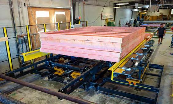
Powered In Feed conveyor section, Chain drive under top and bottom plate for access to inspect sheathing fasteners – 12’W x 16’L, adjustable working height from 28” to 34”.
Powered Out-Feed conveyor section, full-width, HD roll-top for easy access to banding operation. 12’W x 16’L, adjustable working height from 28” to 34”. Here are some of the features of the ProStack Wall Panel Stacker:
• Wall Length Max – 16’
• Wall Height Range – 8’ to 12’
• Material 2×4″ through 2×8″
• Total Weight capacity – 6,000 lbs.
• Total stack Height Max – 6’
• This unit stacks on-center
• System is able to stack on-center layers that have multiple wall segments
• Siemens® HMI touch-screen controls
• Full manual override controls via HMI
• Speed – 45-60 seconds per wall layer
• NO overhead components = no overhead hazards or annual inspections
765-751-9990
2016 Triad Wall Assembly Equipment
2016 Triad exterior and interior wall panel lines with conveyors and terminal stations. Builds 2×4 and 2×6 walls up to 16’ in length with wall heights from 6’-9” to 10’-2” and includes Component Nailer model FTN and panel lift model XPL1000:
Exterior line includes (2) sets of Rough Opening Assembly tables model RO-CAT, framing table model Gen II with manual nail-gun tool dollies each side & stud locators at 16” and 24” o.c., squaring and sheathing table model Gen II with staple & routing combo bridge & side shift for seams @ 3” & 6” o.c. fasteners, top & bottom plate gun mounts for 6” o.c. fasteners, auto stop & tilt features, (3) 10 ft skatewheel conveyors, (4) 20 ft x 36″ roller conveyors and (4) powered infeed conveyors with chain track.
Interior line includes Rough Opening Assembly table model RO-CAT, framing table model Diamond Quad with manual nail-gun tool dollies each side, pop-up rollers & stud locators at 16” and 24” o.c., (2) 10 ft skatewheel conveyors, (4) 20 ft x 36″ roller conveyors.
System sold for over $223,000 new. Sold as one system only. 110 volt, 1 phase electrical required. 100 PSI air required.

PHONE: 800-289-5627 FAX: 800-524-4982 Read/Subscribe online at www.componentadvertiser.com Don’t Forget! You Saw it in the Adverti$$er April 2023 #15285 Page #70 A dverti $ er Component manufaCturing m The 765-751-9990 www.woodtechsystems.com
www.woodtechsystems.com
$12,500 FOB NE
Wasserman & Associates
800-382-0329
www.wasserman-associates.com
New Panels Plus Wall Panel Framing Equipment
Consider Panels Plus wall panel assembly equipment for manufacturers of wood or steel wall panels, floor-panels, and related framing components. Panels Plus is an employee owned, ISO certified, manufacturing company that builds state-of-the-art equipment featuring durable construction, with fit and finish second to none in the structural building component industry. The referenced base framing table allows you to assemble from 7-12 foot wall heights, at industry standard 16 foot lengths, at a working height of 29 to 32 inches. This framer design includes controls at each end of table, squaring stops and pneumatic clamping for consistent wall panel quality. Frames 2x4 or 2 x 6 walls, with color-coded, steel stud locators at 16 and 24 inches O.C. spacing. Includes pop-up skate wheels for easy transfer of completed wall frame. Framing table can be configured to receive wall framing light bars, other options include custom buildable wall heights, lengths and auto-indexing of optional 2 or 3 tool carriages.
Additionally from Panels Plus are sheathing tables with features that include foot pedal control at squaring end of table, with squaring stops, roller conveyors at both sides, single pendant controls for bridge, tool spacing at 6 inch centers with 3 inch bridge shift for offset nailing. Tool bridges can accommodate from 2 x 4 to 2 x 8 walls, with seam tilt being standard equipment Panels Plus Tool Bridges are available with single beam or dual beam design for two different tool mounts on one bridge. Squaring stations, sub-component tables, conveyors and panel lifts are also available to complete the configuration of the wall panel assembly line. Price includes factory installation and training. 50 CFM at 120 psi air. 120 or 230 volt, 1 phase electrical.


2006 Panels Plus Squaring Table with Multi-Tool Panel Bridge

• Wall Lengths to 16'
• Powered Height Adjustment/ Clamping from 7'-11" to 12'-4"
• Hand Crank Panel Bridge with Remote Fire and Tilt
• Staple Gun Spacing at 6" Centers with 3" Bridge Shift
• Includes 21 Hitachi Staple Guns
• The Table & Bridge are Stored Inside
FOB KS $39,900 NOW $37,500
PHONE: 800-289-5627 FAX: 800-524-4982 Read/Subscribe online at www.componentadvertiser.com Don’t Forget! You Saw it in the Adverti$$er April 2023 #15285 Page #71 A dverti $ er Component manufaCturing m The 765-751-9990 www.woodtechsystems.com
CLICK HERE for more information NEW!
PANEL EQUIPMENT
New Component Table with Skatewheel Conveyors Lift & Extend Skatewheel Conveyors. 10' x 10' Work Area with Squaring Lip. Gun Holster & Nail Tray.
800-382-0329 www.wasserman-associates.com
A dverti$er Component manufaCturing S erving the S tructural B uilding c omponent S i ndu S try The
By Thomas McAnally TheJobLine.com
Building Your Own Home – Part II: One Home, Two Loans
Homeowners usually have to deal with obtaining a mortgage when buying a home, but they seldom need to convince a bank to loan them the same amount on a piece of dirt, with promises to make a home worth a mortgage. As the Homeowner/General Contractor, I not only had to qualify for the loan, I had to qualify to be our General Contractor. It took an essay about my prior experience building commercial offsite structures and a little bit of residential construction experience plus a supportive loan officer to gain their trust. Now, all I have to do is follow through, with no experience using local contractors, in a wildly inflated market, using very expensive money. Piece of cake…. gulp!
With the bank willing to “consider” funding a construction loan, my next step was to pull together plans and a price. I still wanted to use the original builder, but with them only drying in the home I needed more trades. The first step is having a set of plans. My wife and I took elements of several plans and features that we both liked and worked with the builder to develop a floor plan and elevations. We then picked fixtures and appliances, including kitchen, heating, cooling, and water heater options. Adding specifications for construction materials, finishes, and features rounded out our package. With this “package” we could provide enough information to subcontractors to get estimates.
I did online searches, my wife asked friends at work, and I leveraged the few contractors I already knew from building my shop for their help. Getting three bids is an industry standard, but in this market, it’s hard to get three subs from the same trade to even return a call, let alone quote. We found at least two subs for each trade who would submit a price. PDF plans and specs in hand, I started emailing each sub and waiting for their bids. After a couple of weeks, it was clear that they were very busy and I needed to be proactive if I wanted to build this home in 2023. Add another month and the prices are in. Even sending out identical packages, bids were all over the place. Going back and forth for another week or two got everyone on the same page, including me. I learned a lot from that process as each sub was an expert in their trade and was willing to help me not make big mistakes.

Finally, I had enough prices to put together a massive spreadsheet workbook with a sheet for each trade and a sheet to bring all of the totals together. That helped me to not only pull together prices but also to consider what-if’s and see how plugging in different contractors might affect the total. I could see where items were missing and where we had duplicate work bid by different trades, overlapping and driving up the price. Finally, armed with the spreadsheet, plans, and expected price, I met with the banker.
It didn’t take long for the bank to get onboard with the project with one caveat, the dreaded pre-construction appraisal. For two weeks, I sweated bullets waiting for what I was sure would be a low number, proving my ineptitude in thinking I could do this and driving up the upfront costs. In the end, the number came in over the estimated price. Well, that is another level of self-doubt, but onward! We signed a contract with the builder and now we expect to break ground in mid to late May. Now, I just need to clear a few more trees before we begin.
Next Month: Site work and utilities

PHONE: 800-289-5627 FAX: 800-524-4982 Read/Subscribe online at www.componentadvertiser.com Don’t Forget! You Saw it in the Adverti$$er April 2023 #15285 Page #72 A dverti $ er Component manufaCturing m The
PANEL EQUIPMENT
2007 VIKING 16' X 12' SQUARING TABLE
WITH SHEATHING BRIDGE
• 16' x 12' Squaring Table with Powered Width Adjustment & Powered Chain


Conveyor
• Wall Panel Lengths up to 16', Wall Panel Heights from 4'-0" to 12'-2"
• Swing Gates at Both Ends of Squaring Table
• Automated Field & Edge Nailing
Driving by Panel Pro Event Software & Your Programmed Nailing Patterns
• Simple Touchscreen Controls
• 2 Tool Carriages for Sheathing Nailing with Tilt Function for Seams
• 2 Paslode Nail Guns with High Load Coil Tray
• Auto Sheathing Bridge Return

• Includes 4 Pallets of Magnum Coil Nails (2 3/8 x .113)
• 480 Volt / 3 Phase
$29,900 FOB KS.
Wasserman & Associates
800-382-0329
www.wasserman-associates.com
2021 Triad Router Bridge & Portion of V-Track
2021 Triad Routing Bridge with approximately (20) feet of v-track. Fits over tables that build up to 12′ nominal height wall panels. Includes powered automatic bridge return, powered vertical router movement, manual fine adjustment wheel, manual vertical router travel with chain drive and (1) Milwaukee router, catalog #5625-20 120 volt, 1 phase, 15 Amp electrical required. No table included.
$28,970 NOW $5,000 FOB BC
Wood Tech Systems
765-751-9990
www.woodtechsystems.com
New Panels Plus Floor Cassette Framing Station
Price: $Call for pricing
FOB: MN
IBS Tool Bridge & Router Bridge
IBS multi-tool bridge with (24) tool stations. Bridge features auto-return, button controls and laser guide mount. Fits up to 12′ nominal rail centers. IBS router bridge features (1) router, laser guide mount and lever-switch button controls. Fits up to 12′ nominal rail centers. Sold as a pair. Includes all available floor mounted, v-rail. Both bridges missing laser sub-assembly. 120vac, 120psi air.
$15,975 FOB UT
New Panels Plus floor framing machine, supports the structural members creating floor sections from 2" x 6" LVL through 2" x 10" to 2" x 12" dimensional lumber, 20" deep wood floor trusses or engineered wood / I-joists. Standard footprint of floor panels (cassettes) up to 12' wide x 45' long. Table consists of a fixed section and a track-guided, moveable section controlled by either a foot switch or push-buttons.
Reconditioned dual 16’ foot long light bars, includes spare light board. Light bars are compatible with all light-bar equipped or ready IBS/Comsoft, Panels Plus, etc. wall panel equipment driven by ITW (IBS) or other compatible design software. 110 volt, single phase electrical. $18,890 NOW $16,550 FOB MN.
Wood Tech Systems
765-751-9990
www.woodtechsystems.com
Wood Tech Systems


765-751-9990
www.woodtechsystems.com
New Wall Panel Lift
• 8' to 12' Wall Heights
• 1,000 Lb Capacity
• Weight: 120 Lbs
• Excludes: Electric Hoist & Freestanding Bridge Crane

$1,950 FOB NE
Wasserman & Associates
800-382-0329
www.wasserman-associates.com
Includes a series of color-coded locator pins at 16", 19.2 and 24" on-center spacing and clamping with squaring feature including foot pedal control. The locators individually flip down if a joist comes out on top of them. After the floor is complete and unclamped, the floor section can be raised up on skate-wheel conveyors and rolled out or lifted off the table using an overhead crane. Table height is 24.5", OAL 45.5 ft, OAW 14.5 ft. 120 volt, 1 phase, 15 Amp electrical required. 90 to 120 PSIG at 15 CFM air required.
PHONE: 800-289-5627 FAX: 800-524-4982 Read/Subscribe online at www.componentadvertiser.com Don’t Forget! You Saw it in the Adverti$$er April 2023 #15285 Page #73 A dverti $ er Component manufaCturing m The A dverti$er Component manufaCturing S erving the S tructural B uilding c omponent S i ndu S try The 765-751-9990 www.woodtechsystems.com NEW!
IBS/Comsoft Wall Panel Light Bars
Alpine has it all—the right equipment, user-friendly software and dependable hardware to improve your teams efficiency. Alpine delivers the complete package for success—including comprehensive support and service that sets us apart within our industry.


Ask those who know. They’ll tell you about the people at Alpine who make a difference.


“Over the years Alpine ensured our quality and production kept improving. Working with Alpine has been a 22 year friendship as well as a partnership!”
— Roy Bedient Manager/ Production Manager, Warman Truss
BUILD MORE. alpineitw.com | 800.521.9790
Triad 12 ft Gen II Sheathing
Bridge & Track
Triad Generation II nail tool bridge with 60 ft of v-track, refurbished by Triad in 2021. Maximum panel height clearance 12′-3″. Includes locations for (3) tool mounts along the middle beam, top & bottom plate tool mounts, tilt-tool option, joy-stick controls, power bridge return, e-stop button, all available Paslode tool mounts, manual and all available spare parts. 120 volt, 1 phase electrical required. 100 PSI air required. $75,971 NOW $25,000 FOB CO


PHONE: 800-289-5627 FAX: 800-524-4982 Read/Subscribe online at www.componentadvertiser.com Don’t Forget! You Saw it in the Adverti$$er April 2023 #15285 Page #75 A dverti $ er Component manufaCturing m The NEW! New Panels Plus Combination Table Price: $Call for pricing FOB: MN 765-751-9990 www.woodtechsystems.com 765-751-9990 www.woodtechsystems.com 2007 Panels Plus Steel Wall Panel Sheathing Station $74,970 NOW $68,997 FOB MN 765-751-9990 www.woodtechsystems.com


LIGHT GAUGE STEEL SHEATHING STATION

The Light Gauge Steel Sheathing Station offers flexibility in wall height, sheathing thickness, and screw spacing and screws sheathing to steel wall panels to ensure quality panels every time.
This model can be stand-alone or integrated into a full production line.


Various sizes and configurations are available.
BENEFITS
• Ergonomic working height
• Single person operation
• Flexibility with fastener spacing

• Fastens consistently and accurately


$26,977 NOW $19,997 FOB MD
Triad / Viking Wall Equipment
Triad squaring table with two bridges and one Viking power conveyor. Either bridge fits on the squaring table. Builds from 6′-9″ to 12′-3″ tall wall panels to 16′-0″ long. Triad squaring table, model G2SHSQ, has powered clamp / unclamp controls on either end of the fixed side of table.
Triad nailing bridge, model PSTT, has (24) tool mount locations with Paslode tool mounts, auto return and bottom plate laser sight mount. Changed by owner from staple tools to nail tools. Router bridge is manual travel. Viking powered conveyor 23 ft long with support platforms alongside both chains. Forward powered drive only. Foot pedal controls for drive motors. 120 volt, 1 phase electrical required. 100 PSI air required.
PHONE: 800-289-5627 FAX: 800-524-4982 Read/Subscribe online at www.componentadvertiser.com Don’t Forget! You Saw it in the Adverti$$er April 2023 #15285 Page #77 A dverti $ er Component manufaCturing m The NEW 12' X 16' FRAMING TABLE 800-382-0329 | www.wasserman-associates.com • Add $11,900 for Sub-Component Layup Tables with Pop-up Skatewheel Conveyors • EQUIPMENT FINANCING available from SLS Financial Services $38,000 FOB NE • Pop-up Skatewheel Conveyor • Powered Height Adjustment (6'-11" to 12'-5" wall heights) • Fixed Squaring Stops • Excludes Tool Dollies • 110 Volt / 20 Amps • Add $6,000 for Stud Locators at 16" & 24" O.C. • Add $2,750 for 1 Pair of 15' Skatewheel Conveyor with Stands NEW! 765-751-9990 www.woodtechsystems.com
WWW.PANPLUS.COM 1-866-726-7587
Design Connections


The Designer Shortage— Where Can We Find Them
Achallenge for the component industry is brewing no matter if you are located in an area where new home construction continues to be strong or your market is slowed by the combined effects of high interest rates and stubbornly high inflation. Be it single family or multi-family, new designers are not entering the industry as quickly as old grey hairs like me are leaving.

From the mid to late 1990s until the 2008 crisis approached, component designers were in high demand, commanding ever higher salaries. The conditions at the time led Thom McAnally and I to create the Component Systems Institute to help train new designers for the industry. In many cases, design capacity was the limiting constraint for truss plant capacity across North America, and design salaries climbed from the demand pressure. As the market slowed and even collapsed, designers that had been hired at high salary levels were often the first to be let go, as business owners understandably sought to cut costs. We’ve seen that many designers left the truss and component industry, never to return. Some eventually returned to the business as word of increasing demand brought experienced people back, but it certainly feels like the designer shortage has stayed with us throughout this recent boom.
New Designer
Today, we are once again looking at an uncertain economic future, combined with demographic factors common to most industries that see workers transitioning to retirement at a faster rate than they are being replaced. Understanding that it is important to keep an eye on the bottom line, component manufacturers also need to try to maintain a long-term view of the importance of skilled designers to their long-term business success. To the greatest extent possible, component manufacturers need to continuously find and develop new designers. Some will be the backbone of your business in the years to come, and some will flame out and be gone before you know it.
PHONE: 800-289-5627 FAX: 800-524-4982 Read/Subscribe online at www.componentadvertiser.com Don’t Forget! You Saw it in the Adverti$$er April 2023 #15285 Page #78 A dverti $ er Component manufaCturing m The Continued next page
Geordie Secord, Senior Recruiter TheJobLine.com – Canada
So, if you’re looking for designers, where can you find them? Here are a few suggestions.
Local community colleges and trade schools: Graduates of these programs will usually have CAD experience, along with some experience reading blueprints and spatial aptitude. I would encourage you to think about engineering technologists, drafting, and carpentry programs. And while it may seem counterintuitive, I have a caution about recruiting from architectural programs – those programs offer many of the proper skills, but in my experience people in these programs have an artistic/creative need that isn’t met long-term in a component designer role.

Your existing employees: Aside from the positive aspects of having your current employees see the possibility of future advancement, promoting from within offers other benefits as well. One of the big wins is that they are already local, so they probably are less likely to leave the area where they have an established network of family and friends.

Local framers: While many framers will happily work their entire careers on site, I have met more than one who is tired of working bent over in the hot sun/freezing cold all day every day. So long as they are intelligent and comfortable with technology, they can become great component designers. They are already familiar with reading blueprints and visualizing how that translates into the final building. Plus, their insights may be a real benefit to your other designers as well.
Of course, both Thom and I are always here to help you find experienced designers, so be sure to reach out if that is what you need. Just don’t forget that those experienced people needed to start somewhere, and it’s up to all of us to keep filling that void.
If you want help finding that next perfect component designer or design job in Canada, please contact me. If your work is in the mass timber world anywhere in North America, I’d love to talk to you about connecting you to that next great job or candidate. You can reach me at secord@thejobline.com, or 800-289-5627 ext. 2. I’m also happy to engage at: LinkedIn.com/in/geordiesecord. www.thejobline.com
PHONE: 800-289-5627 FAX: 800-524-4982 Read/Subscribe online at www.componentadvertiser.com Don’t Forget! You Saw it in the Adverti$$er April 2023 #15285 Page #79 A dverti $ er Component manufaCturing m The


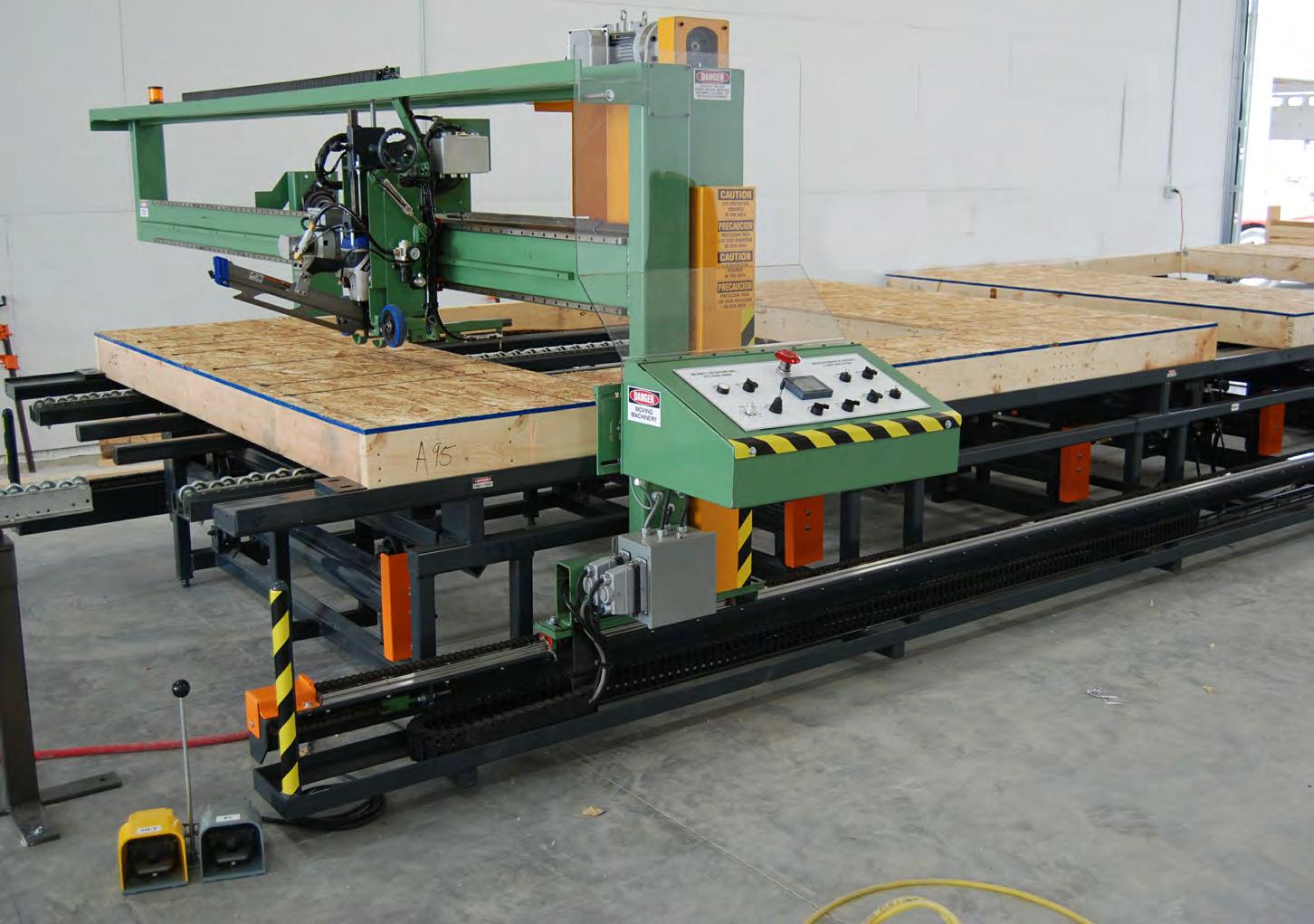
One Table System $87,900 Wasserman & Associates Framing Table With Panel Bridge -Laser Pointer -Bridge Auto Return -Bridge Tilt at Sheathing Seams -Programmable Fastener Patterns -Pop-Up Skatewheel Conveyors -6’-11” to 12’-5” Wall Heights -Fixed Squaring Stops -No Floor Rails *Includes Installation Support in the United States & Canada Wasserman & Associates 2341 Shepard Rd Milford NE 68405 Phone: 800-382-0329 Web: www.wasserman-associates.com $93,500 Additional Information Here
•

•Control Duality • Control Consistency • Control Costs an Autonomous Mode - UNMANNED operation VouTube
- Twin Gantry - Servo Controlled
Accommodates 6 high-capacity pneumatic nailers
Auto-Sizing, Configurable Spacing Plate Fire
Auto-nailing of window openings, top & bottom
LIVE Video Assist Locating Technology
278% more air tank capacity
•Multi-tool
•
•
•
•
•
Nails a 121 stud in approximately 2-4 seconds
Automatic tilting of nail guns [for example on seams)
Auto-positioning nailers, at 1611 & 2411 OC
Easily set 11rules11 for your nailing profile[s)
Vertical axis servo control, for wall thicknesses
Laser sensors for material detection
1t fire nails over openings)
• Network compatible We've been helping professional builders take control of their operations for nearly 60 years. Put our experience to work for you! Give us a call or check out our NEW web site: •w' Triad Machines 800-568-7423 ext. 126 www.TriadMachines.com
•
•
•
•
•
[won
lliiii:�


2003 JDH TRUSSMASTER SIDEOFFLOADING TRUSS TRAILER

10,000 Lb Tandem Axles (Dual Wheels). 26,000 GVWR. Deliver Trusses Vertically. Stretch from 18' to 38'. Raise Loads
Hydraulically. Air Brakes.
$6,900 FOB CA
Wasserman & Associates
800-382-0329
www.wasserman-associates.com
TRUCKS & TRAILERS
• Modified by LMI TENN
• 8" Floor Cross Members
• Reinforced Roof
• 22.5 Tubeless Tires
• Sl iding Tandem Axle (for weight distribution) (FOB PA) $9,900
Wasserman & Associates 800-382-0329
www.wasserman-associates.com
Step Deck Roller Trailer

40'-0" Lower Deck, 12'-6" Upper Deck
Hydraulic Tilt on Lower Deck
Lower Deck has 3 Split Load Lifts
Roller Locks (upper & lower decks)
GVWR: 37,000 KG (81,400 LB)
Air Ride Suspension
Tires & Brakes are Good
Winches & Straps
Price in US Dollars
$30,000 NOW $24,900 FOB ON
Wasserman & Associates
800-382-0329
www.wasserman-associates.com
2006 Stoll 30′ Gooseneck roll off trailer features a hydraulic lift neck and locking rollers. Brakes have approximately 20% life left, 6 tires have approximately 60% life left, and 2 tires have approximately 25% life left. Lights are all working and DOT expired 12/31/22.
As is, Where is $11,990 FOB OH Wood Tech Systems
765-751-9990
www.woodtechsystems.com
1987 Barnes Pole Trailer
1987 Barnes pole trailer, model RTY. Carries trusses peak down, with spans from 28’6″ to 46′-0″. Includes bolster arms for shorter trusses, center chains and split support tubes. Has current Pennsylvania DOT inspection valid through March of 2023.


$8,129 NOW $6,909 FOB PA
Wood Tech Systems
765-751-9990
www.woodtechsystems.com
• 2007 Freightliner M2 Flatbed Truck (168,000 Miles)

• New Tires in 2022 ($12,000 Value)
• Hiab 322E-7 Hipro Crane (FOB WA) $89,000 NOW $75,000 800-382-0329 | www.wasserman-associates.com

• Hydraulic Front End
• Fixed Tandem
• Spring Suspension
• Air Brakes (Good Condition)
• Locking & Controllable Rollers
• Headache Rack
• Out of service in 2021 (DOT is not current)
$19,750 FOB KS
Wasserman & Associates
800-382-0329
www.wasserman-associates.com
• 18 HP Spindle
Typewriter Tool Changer

• X, Y and Z Servo Axis
5 Position
• Q-CORE Controller (THM Version 8.73 - Windows7)
• Reads NC Files via Network or USB Flash Drive
• 5' x 20' Fixed Table
• Roller Hold Down
• Program Side Fence
• Auto Tool Length
• Auto Lubrication
• Excludes Dust Collector
• The seller was cutting OSB Sheathing and 1 1/4" TimberStand Stair Stringers
• Video available upon request
$29,500 FOB MN
Wasserman & Associates
800-382-0329
www.wasserman-associates.com
2022 Powermatic
Dual-Bag Dust Collector

2022 Powermatic Dual Bag Dust Collector. Industrial dust collector, dual-bag, 1800 CFM with 6″ port. Includes supply of 6″ flex hose. System has 10 Cu. Ft. capacity. 3HP, 3Ph, 5 amp, 460/V with onboard starter. $5,497 FOB VA
Wood Tech Systems
765-751-9990
www.woodtechsystems.com
PHONE: 800-289-5627 FAX: 800-524-4982 Read/Subscribe online at www.componentadvertiser.com Don’t Forget! You Saw it in the Adverti$$er April 2023 #15285 Page #83 A dverti $ er Component manufaCturing m The
2006 A-NU-PROSPECT
1995 Pines 45' Chip Trailer
2007 Freightliner Truck with Hiab Knuckle Boom Crane
2006 Stoll 30′ Gooseneck Roll Off Trailer
MISC.
2003 Thermwood C53DT CNC Router
with
2005 JDH Trussmaster 35'-50' Stretch Roll-Off Trailer
Truss Design Value Comparison Tables

Timber Products Inspection has compiled design value comparison tables for several popular species and species groups as a helpful tool for truss manufacturers to determine if a lumber grade and/or lumber species substitution satisfies the original truss design. The data used comes from the 2018 National Design Specification® (NDS®) for Wood Construction Supplement and is normalized to a 2x4 application. These tables can be used to compare the design values for visual grades of 2x6–2x12 as well, since the size adjustment factors are consistent regardless of grade and/or species.

These 2x4 table values are valid for comparing visual grades of 2x4 to 2x4, just as they would be valid for comparing visual grades of 2x6 to 2x6, 2x8 to 2x8, 2x10 to 2x10, and 2x12 to 2x12.
Note 1 – These tables were not intended to be used for size substitution purposes, since size substitutions can cause other practical issues beyond just design value application.
Note 2 – MSR grades can be compared to each other using these tables, regardless of size. MSR grades can be compared to visual grades using these tables for 2x4 only, though; any other size would require the size adjustment factors to be applied to the visual grade’s design values.
Example of table use – the truss design calls for 2x6 SPF NO.1, and the substitution considered is a 2x6 SYP NO.2 (different species and different grade). The tables provide the following 2x4 values:
ITEMFbFtFvFc-perpFc-parMOEG
2x4SPFNO.1130067513542513001.40.42
2x4SYPNO.2110067517556514501.40.55
The SYP NO.2 meets or exceeds SPF NO.1 for the Ft, Fv, Fc-perp, Fc-par, MOE, and G. But since the Fb is lower for SYP NO.2, it cannot be substituted for SPF NO.1.
The next higher visual grade of SYP NO.1 can be compared for possible substitution. The tables provide the following 2x4 values:
ITEMFbFtFvFc-perpFc-parMOEG
2x4SPFNO.1130067513542513001.40.42
2x4SYPNO.11500100017556516501.60.55
The SYP NO.1 exceeds SPF NO.1 for the Fb, Ft, Fv, Fc-perp, Fc-par, MOE, and G. So the 2x6 SYP NO.1 can be substituted for 2x6 SPF NO.1.
If you have questions or would like more information, please call us at 770-922-8000 or visit http://www.tpinspection.com/.
PHONE: 800-289-5627 FAX: 800-524-4982 Read/Subscribe online at www.componentadvertiser.com Don’t Forget! You Saw it in the Adverti$$er April 2023 #15285 Page #84 A dverti $ er Component manufaCturing m The Continued next page
David Conner, Vice President, Timber Products Inspection

PHONE: 800-289-5627 FAX: 800-524-4982 Read/Subscribe online at www.componentadvertiser.com Don’t Forget! You Saw it in the Adverti$$er April 2023 #15285 Page #85 A dverti $ er Component manufaCturing m The Continued next page TRUSS DESIGN VALUE COMPARISON TABLES2x4 Ver-20230225 based on 2018 NDS 2x4 DOUGLAS FIR-LARCH 2x4 DOUGLAS FIR-LARCH (NORTH) 2x4 DOUGLAS FIR-SOUTH GRADE Fb Ft Fv Fc-perp Fc-par MOE G GRADE Fb Ft Fv Fc-perp Fc-par MOE G GRADE Fb Ft Fv Fc-perp Fc-par MOE G SEL STR 225015001806251950 1.9 0.50 SEL STR 200012001806252150 1.9 0.49 SEL STR 200013501805201800 1.4 0.46 NO.1&BTR 180012001806251750 1.8 0.50 NO.1&BTR 170011001806252050 1.8 0.49 NO.1&BTR NA NANANANA NANA NO.1 150010001806251700 1.7 0.50 NO.1 12507501806251600 1.6 0.49 NO.1 13509001805201650 1.3 0.46 NO.2 13508501806251550 1.6 0.50 NO.2 12507501806251600 1.6 0.49 NO.2 12507751805201550 1.2 0.46 NO.3 775475180625875 1.4 0.50 NO.3 700450180625925 1.4 0.49 NO.3 750450180520875 1.1 0.46 STUD 575350180625800 1.4 0.50 STUD 500325180625850 1.4 0.49 STUD 725450180520875 1.1 0.46 CONST 700450180625850 1.5 0.50 CONST 650400180625900 1.5 0.49 CONST 9756001805201650 1.2 0.46 STAND 10006501806251650 1.4 0.50 STAND 9505751806251800 1.4 0.49 STAND 5503501805201400 1.1 0.46 UTIL 5753751806251400 1.3 0.50 UTIL 5253251806251450 1.3 0.49 UTIL 250150180520900 1 0.46 2x4 SPRUCE-PINE-FIR 2x4 SPRUCE-PINE-FIR (SOUTH) 2x4 ALASKA SPRUCE GRADE Fb Ft Fv Fc-perp Fc-par MOE G GRADE Fb Ft Fv Fc-perp Fc-par MOE G GRADE Fb Ft Fv Fc-perp Fc-par MOE G SEL STR 185010501354251600 1.5 0.42 SEL STR 19508501353351350 1.3 0.36 SEL STR 210013501603301350 1.6 0.41 NO.1 13006751354251300 1.4 0.42 NO.1 13006001353351200 1.2 0.36 NO.1 14009001603301250 1.5 0.41 NO.2 13006751354251300 1.4 0.42 NO.2 11505251353351150 1.1 0.36 NO.2 13007501603301200 1.4 0.41 NO.3 750375135425725 1.2 0.42 NO.3 675300135335650 1 0.36 NO.3 750450160330675 1.3 0.41 STUD 725375135425750 1.2 0.42 STUD 650300135335650 1 0.36 STUD 725425160330700 1.3 0.41 CONST 10005001354251400 1.3 0.42 CONST 8754001353351200 1 0.36 CONST 10005751603301250 1.3 0.41 STAND 5502751354251150 1.2 0.42 STAND 5002251353351000 0.9 0.36 STAND 5503251603301050 1.2 0.41 UTIL 275125135425750 1.1 0.42 UTIL 225100135335675 0.9 0.36 UTIL 275150160330700 1.1 0.41 2x4 HEM-FIR 2x4 HEM-FIR (NORTH) 2x4 ALASKA HEMLOCK GRADE Fb Ft Fv Fc-perp Fc-par MOE G GRADE Fb Ft Fv Fc-perp Fc-par MOE G GRADE Fb Ft Fv Fc-perp Fc-par MOE G SEL STR 210013501504051700 1.6 0.43 SEL STR 195011501454051950 1.7 0.46 SEL STR 195012001854401350 1.7 0.46 NO.1&BTR 165010501504051550 1.5 0.43 NO.1&BTR 180010501454051750 1.7 0.46 NO.1&BTR NA NANANANA NANA NO.1 14509251504051550 1.5 0.43 NO.1 15008501454051650 1.6 0.46 NO.1 13508251854401250 1.6 0.46 NO.2 12507751504051450 1.3 0.43 NO.2 15008501454051650 1.6 0.46 NO.2 12007001854401200 1.5 0.46 NO.3 750450150405825 1.2 0.43 NO.3 850475145405975 1.4 0.46 NO.3 700400185440675 1.4 0.46 STUD 550325150405750 1.2 0.43 STUD 625350145405875 1.4 0.46 STUD 700400185440675 1.4 0.46 CONST 675400150405800 1.3 0.43 CONST 775450145405925 1.5 0.46 CONST 9505501854401250 1.4 0.46 STAND 9756001504051550 1.2 0.43 STAND 11506501454051750 1.4 0.46 STAND 5253001854401050 1.3 0.46 UTIL 5503251504051300 1.1 0.43 UTIL 6503501454051500 1.3 0.46 UTIL 250150185440700 1.2 0.46 2x4 E. HEMLOCK-BALSAM FIR 2x4 E. HEMLOCK-TAMARACK 2x4 COAST SITKA SPRUCE GRADE Fb Ft Fv Fc-perp Fc-par MOE G GRADE Fb Ft Fv Fc-perp Fc-par MOE G GRADE Fb Ft Fv Fc-perp Fc-par MOE G SEL STR 18508501403351350 1.2 0.36 SEL STR 18508501705551350 1.2 0.41 SEL STR 195014001254551350 1.7 0.43 NO.1 11505251403351150 1.1 0.36 NO.1 11505251705551150 1.1 0.41 NO.1 13508251254551250 1.5 0.43 NO.2 850400140335925 1.1 0.36 NO.2 850400170555925 1.1 0.41 NO.2 13508251254551250 1.5 0.43 NO.3 525225140335525 0.9 0.36 NO.3 525225170555525 0.9 0.41 NO.3 775475125455700 1.4 0.43 STUD 475200140335550 0.9 0.36 STUD 475200170555550 0.9 0.41 STUD 775475125455700 1.4 0.43 CONST 6753001403351050 1 0.36 CONST 6753001705551050 1 0.41 CONST 10506501254551300 1.4 0.43 STAND 375175140335850 0.9 0.36 STAND 375175170555850 0.9 0.41 STAND 6003501254551100 1.3 0.43 UTIL 17575140335550 0.8 0.36 UTIL 17575170555550 0.8 0.41 UTIL 275175125455725 1.2 0.43
PHONE: 800-289-5627 FAX: 800-524-4982 Read/Subscribe online at www.componentadvertiser.com Don’t Forget! You Saw it in the Adverti$$er April 2023 #15285 Page #86 A dverti $ er Component manufaCturing m The TRUSS DESIGN VALUE COMPARISON TABLES2x4 2x4 NORTHERN SPECIES 2x4 WESTERN CEDARS 2x4 WESTERN WOODS GRADE Fb Ft Fv Fc-perp Fc-par MOE G GRADE Fb Ft Fv Fc-perp Fc-par MOE G GRADE Fb Ft Fv Fc-perp Fc-par MOE G SEL STR 14506251103501250 1.1 0.35 SEL STR 15009001554251150 1.1 0.36 SEL STR 13506001353351200 1.2 0.36 NO.1 925400110350975 1.1 0.35 NO.1 1050625155425925 1 0.36 NO.1 10004501353351050 1.1 0.36 NO.2 925400110350975 1.1 0.35 NO.2 1050625155425725 1 0.36 NO.2 10004501353351000 1 0.36 NO.3 525225110350575 1 0.35 NO.3 600375155425425 0.9 0.36 NO.3 550250135335600 0.9 0.36 STUD 500225110350575 1 0.35 STUD 600350155425400 0.9 0.36 STUD 575225135335600 0.9 0.36 CONST 7003251103501050 1 0.35 CONST 800475155425850 0.9 0.36 CONST 7753501353351100 1 0.36 STAND 400175110350875 0.9 0.35 STAND 450275155425650 0.8 0.36 STAND 425200135335925 0.9 0.36 UTIL 17575110350575 0.9 0.35 UTIL 225125155425425 0.8 0.36 UTIL 200100135335600 0.8 0.36 2x4 ALASKA CEDAR 2x4 ALASKA YELLOW CEDAR 2x4 YELLOW CEDAR GRADE Fb Ft Fv Fc-perp Fc-par MOE G GRADE Fb Ft Fv Fc-perp Fc-par MOE G GRADE Fb Ft Fv Fc-perp Fc-par MOE G SEL STR 17009251655251150 1.4 0.47 SEL STR 200012002255101350 1.5 0.46 SEL STR 180010501755401350 1.6 0.46 NO.1 14507751655251000 1.3 0.47 NO.1 13507752255101200 1.4 0.46 NO.1 12007001755401150 1.4 0.46 NO.2 1200625165525850 1.2 0.47 NO.2 12006752255101150 1.3 0.46 NO.2 12007001755401150 1.4 0.46 NO.3 675375165525475 1.1 0.47 NO.3 700375225510650 1.2 0.46 NO.3 700400175540650 1.2 0.46 STUD 675375165525475 1.1 0.47 STUD 675375225510650 1.2 0.46 STUD 675400175540675 1.2 0.46 CONST 900500165525950 1.2 0.47 CONST 9255002255101250 1.3 0.46 CONST 9255501755401200 1.3 0.46 STAND 500275165525775 1.1 0.47 STAND 5002752255101050 1.1 0.46 STAND 5253001755401050 1.2 0.46 UTIL 250125165525500 1 0.47 UTIL 250125225510675 1.1 0.46 UTIL 250150175540675 1.1 0.46 2x4 ASPEN 2x4 NORTHERN WHITE CEDAR 2x4 PORT ORFORD CEDAR GRADE Fb Ft Fv Fc-perp Fc-par MOE G GRADE Fb Ft Fv Fc-perp Fc-par MOE G GRADE Fb Ft Fv Fc-perp Fc-par MOE G SEL STR 1300750120265825 1.1 0.39 SEL STR 1150675120370850 0.8 0.31 SEL STR 187510501654701325 1.6 0.44 NO.1 925550120265675 1.1 0.39 NO.1 850475120370675 0.7 0.31 NO.1 15758651654701210 1.5 0.44 NO.2 900525120265500 1 0.39 NO.2 825475120370525 0.7 0.31 NO.2 13157151654701005 1.4 0.44 NO.3 525300120265300 0.9 0.39 NO.3 475250120370300 0.6 0.31 NO.3 750415165470575 1.3 0.44 STUD 500300120265300 0.9 0.39 STUD 450275120370300 0.6 0.31 STUD 745415165470580 1.3 0.44 CONST 700400120265625 0.9 0.39 CONST 625375120370625 0.7 0.31 CONST 9755501654701100 1.3 0.44 STAND 375225120265475 0.9 0.39 STAND 350200120370475 0.6 0.31 STAND 550300165470900 1.2 0.44 UTIL 175100120265300 0.8 0.39 UTIL 175100120370325 0.6 0.31 UTIL 250150165470600 1.1 0.44 2x4 REDWOOD 2x4 WESTERN JUNIPER 2x4 COTTONWOOD GRADE Fb Ft Fv Fc-perp Fc-par MOE G GRADE Fb Ft Fv Fc-perp Fc-par MOE G GRADE Fb Ft Fv Fc-perp Fc-par MOE G SEL STR 16509251604251250 1.1 0.37 SEL STR 1350775125770250 0.6 0.42 SEL STR 1300775125320875 1.2 0.41 NO.1 11506751604251000 1.1 0.37 NO.1 1200625125770225 0.6 0.42 NO.1 925550125320700 1.2 0.41 NO.2 1050625160425800 1 0.37 NO.2 975525125770200 0.5 0.42 NO.2 925525125320525 1.1 0.41 NO.3 625375160425450 0.9 0.37 NO.3 550300125770100 0.5 0.42 NO.3 525300125320300 1 0.41 STUD 625350160425450 0.9 0.37 STUD 550300125770100 0.5 0.42 STUD 500300125320300 1 0.41 CONST 825475160425925 0.9 0.37 CONST 750400125770200 0.5 0.42 CONST 700400125320650 1 0.41 STAND 450275160425725 0.9 0.37 STAND 425225125770175 0.5 0.42 STAND 400225125320500 0.9 0.41 UTIL 225125160425475 0.8 0.37 UTIL 200100125770100 0.4 0.42 UTIL 175100125320325 0.9 0.41 Continued next page
PHONE: 800-289-5627 FAX: 800-524-4982 Read/Subscribe online at www.componentadvertiser.com Don’t Forget! You Saw it in the Adverti$$er April 2023 #15285 Page #87 A dverti $ er Component manufaCturing m The TRUSS DESIGN VALUE COMPARISON TABLES2x4 2x4 SOUTHERN PINE 2x4 EASTERN SOFTWOODS 2x4 EASTERN WHITE PINE GRADE Fb Ft Fv Fc-perp Fc-par MOE G GRADE Fb Ft Fv Fc-perp Fc-par MOE G GRADE Fb Ft Fv Fc-perp Fc-par MOE G DNS SEL STR 2,7001,900 175660 2,050 1.9 0.55 DNS SEL STR NANANANANANANA DNS SEL STR NANANANANANANA SEL STR 2,3501,650 175565 1,900 1.8 0.55 SEL STR 18508501403351350 1.2 0.36 SEL STR 18508501353501350 1.2 0.36 NO.1 1,500 1,000 175 565 1,650 1.6 0.55 NO.1 1150 525 140 335 1150 1.1 0.36 NO.1 1150 525 135 350 1150 1.1 0.36 NO.2 1,100 675175565 1,450 1.4 0.55 NO.2 850400140335925 1.1 0.36 NO.2 850400135350925 1.1 0.36 NO.3 650400175565850 1.3 0.55 NO.3 525225140335525 0.9 0.36 NO.3 525225135350525 0.9 0.36 STUD 650400175565850 1.3 0.55 STUD 475200140335550 0.9 0.36 STUD 475200135350550 0.9 0.36 CONST 875500175565 1,600 1.4 0.55 CONST 6753001403351050 1 0.36 CONST 6753001353501050 1 0.36 STAND 475275175565 1,300 1.2 0.55 STAND 375175140335850 0.9 0.36 STAND 375175135350850 0.9 0.36 UTIL 225125175565850 1.2 0.55 UTIL 17575140335550 0.8 0.36 UTIL 17575135350550 0.8 0.36 2x4 BALDCYPRESS 2x4 BEECH-BIRCH-HICKORY 2x4 YELLOW POPLAR GRADE Fb Ft Fv Fc-perp Fc-par MOE G GRADE Fb Ft Fv Fc-perp Fc-par MOE G GRADE Fb Ft Fv Fc-perp Fc-par MOE G SEL STR 18009751606151350 1.4 0.47 SEL STR 215012501957151350 1.7 0.71 SEL STR 15008501454201000 1.5 0.43 NO.1 15008251606151200 1.4 0.47 NO.1 15509001957151050 1.6 0.71 NO.1 1050625145420825 1.4 0.43 NO.2 12006751606151000 1.3 0.47 NO.2 1500900195715850 1.5 0.71 NO.2 1050600145420650 1.3 0.43 NO.3 700375160615600 1.2 0.47 NO.3 850525195715475 1.3 0.71 NO.3 600325145420350 1.2 0.43 STUD 700375160615600 1.2 0.47 STUD 850475195715475 1.3 0.71 STUD 600350145420350 1.2 0.43 CONST 9255001606151100 1.2 0.47 CONST 11506751957151000 1.4 0.71 CONST 800475145420750 1.3 0.43 STAND 525275160615925 1.1 0.47 STAND 650375195715775 1.3 0.71 STAND 450250145420575 1.1 0.43 UTIL 250125160615600 1 0.47 UTIL 300175195715500 1.2 0.71 UTIL 200125145420375 1.1 0.43 2x4 RED MAPLE 2x4 MIXED MAPLE 2x4 MIXED OAK GRADE Fb Ft Fv Fc-perp Fc-par MOE G GRADE Fb Ft Fv Fc-perp Fc-par MOE G GRADE Fb Ft Fv Fc-perp Fc-par MOE G SEL STR 195011002106151250 1.7 0.58 SEL STR 15009001956201000 1.3 0.55 SEL STR 170010001708001150 1.1 0.68 NO.1 13508252106151000 1.6 0.58 NO.1 1050625195620800 1.2 0.55 NO.1 1200750170800925 1 0.68 NO.2 1350775210615800 1.5 0.58 NO.2 1050625195620625 1.1 0.55 NO.2 1200700170800700 0.9 0.68 NO.3 775450210615450 1.3 0.58 NO.3 600375195620350 1 0.55 NO.3 700400170800425 0.8 0.68 STUD 750450210615450 1.3 0.58 STUD 600350195620350 1 0.55 STUD 675400170800400 0.8 0.68 CONST 1050600210615925 1.4 0.58 CONST 800475195620725 1.1 0.55 CONST 925550170800850 0.9 0.68 STAND 575325210615725 1.3 0.58 STAND 450275195620575 1 0.55 STAND 525300170800650 0.8 0.68 UTIL 275150210615475 1.2 0.58 UTIL 225125195620375 0.9 0.55 UTIL 250150170800425 0.8 0.68 2x4 WHITE OAK 2x4 RED OAK 2x4 NORTHERN RED OAK GRADE Fb Ft Fv Fc-perp Fc-par MOE G GRADE Fb Ft Fv Fc-perp Fc-par MOE G GRADE Fb Ft Fv Fc-perp Fc-par MOE G SEL STR 180010502208001250 1.1 0.73 SEL STR 170010001708201150 1.4 0.67 SEL STR 210012002208851300 1.4 0.68 NO.1 13007502208001000 1 0.73 NO.1 1200750170820925 1.3 0.67 NO.1 15008502208851050 1.4 0.68 NO.2 1250750220800800 0.9 0.73 NO.2 1200700170820700 1.2 0.67 NO.2 1450850220885825 1.3 0.68 NO.3 700400220800450 0.8 0.73 NO.3 700400170820425 1.1 0.67 NO.3 825475220885475 1.2 0.68 STUD 700400220800450 0.8 0.73 STUD 675400170820400 1.1 0.67 STUD 825475220885450 1.2 0.68 CONST 950550220800925 0.9 0.73 CONST 925550170820850 1.2 0.67 CONST 1100650220885975 1.2 0.68 STAND 525325220800725 0.8 0.73 STAND 525300170820650 1.1 0.67 STAND 625350220885750 1.1 0.68 UTIL 250150220800475 0.8 0.73 UTIL 250150170820425 1 0.67 UTIL 300175220885500 1 0.68 Continued next page
* 1.8E southern pine marked with a specific gravity of 0.55 on the grade stamp has a shear parallel to grain, Fv, of 175 psi and compression perpendicular to grain, Fc ⊥ , of 565 psi.
NOTEMSR grades and design values are not size-specific.
PHONE: 800-289-5627 FAX: 800-524-4982 Read/Subscribe online at www.componentadvertiser.com Don’t Forget! You Saw it in the Adverti$$er April 2023 #15285 Page #88 A dverti $ er Component manufaCturing m The MSR GRADE FbFt Fc// MOE Applicable to Species Under These Rules-Writing Agencies SPECIES MSR MOE G Fv Fc-perp Grading Rules Agency 1200f-1.2E1,200 600 1,400 1.2 NLGA, WCLIB, WWPA, NELMA 1.0 to 1.9 0.50 180625 1200f-1.3E1,200 600 1,400 1.3 SPIB 2.0 0.51 180670 1200f-1.6E1,200 650 1,550 1.6 SPIB 2.1 0.52 180690 1250f-1.4E1,250 800 1,475 1.4 WCLIB 2.2 0.53 180715 1250f-1.6E1,250 725 1,600 1.6 SPIB 2.3 0.54 185735 1350f-1.3E1,350 750 1,600 1.3 NLGA, WCLIB, WWPA, NELMA 2.4 0.55 185760 1350f-1.4E1,350 750 1,600 1.4 SPIB 1.0 to 1.9 0.50 170625 1400f-1.2E1,400 800 1,600 1.2 NLGA 2.0 0.51 170670 1450f-1.3E1,450 800 1,625 1.3 NLGA, WCLIB, WWPA, NELMA 2.1 0.52 170690 1450f-1.3E1,450 825 1,600 1.3 SPIB 2.2 0.53 170715 1450f-1.5E1,450 875 1,625 1.5 WCLIB 2.3 0.54 170735 1500f-1.4E1,500 900 1,650 1.4 NLGA, WCLIB, WWPA, NELMA 2.4 0.55 170760 1500f-1.5E1,500 900 1,650 1.5 SPIB 1.2 to 1.9 0.49 180625 1500f-1.6E1,500 900 1,650 1.6 SPIB 2.0 to 2.2 0.53 180715 1500f-1.7E1,500 900 1,650 1.7 SPIB 2.3 & higher 0.57 190715 1600f-1.4E1,600 950 1,675 1.4 NLGA Douglas Fir-South 1.0 and higher 0.46 180520 WWPA 1650f-1.3E1,6501,0201,700 1.3 NLGA 1.0 and higher 0.38 135335 1650f-1.5E1,6501,0201,700 1.5 NLGA, SPIB, WCLIB, WWPA, NELMA 1.5 and higher 0.46 160555 1650f-1.6E1,6501,1751,700 1.6 WCLIB 0.43 140405 WCLIB 1650f-1.7E1,6501,0201,750 1.7 SPIB 0.43 150405 WWPA 1700f-1.6E 1700 1,1751,725 1.6 WCLIB 1.6 0.44 155510 1800f-1.5E1,8001,3001,750 1.5 NLGA 1.7 0.45 160535 1800f-1.6E1,8001,1751,750 1.6 NLGA, SPIB, WCLIB, WWPA, NELMA 1.8 0.46 160555 1800f-1.8E1,8001,2001,750 1.8 WCLIB 1.9 0.47 165580 1800f-2.0E1,8001,1751,750 2.0 WCLIB 2.0 0.48 170600 1850f-1.7E1,8501,1751,850 1.7 SPIB 2.1 0.49 170625 1950f-1.5E1,9501,3751,800 1.5 SPIB 2.2 0.50 175645 1950f-1.7E1,9501,3751,800 1.7 NLGA, SPIB, WCLIB, WWPA, NELMA 2.3 0.51 175670 2000f-1.6E2,0001,3001,825 1.6 NLGA 2.4 0.52 180690 2100f-1.8E2,1001,5751,875 1.8 NLGA, SPIB, WCLIB, WWPA, NELMA Hem-Fir (N) 1.0 and higher 0.46 145405 NLGA 2250f-1.7E2,2501,7501,925 1.7 NLGA 1.0 to 1.7 0.55 175565 2250f-1.8E2,2501,7501,925 1.8 NLGA, WCLIB 1.8*0.57* 190*805* 2250f-1.9E2,2501,7501,925 1.9 NLGA, SPIB, WCLIB, WWPA, NELMA 1.9 and higher 0.57 190805 2400f-1.8E2,4001,9251,975 1.8 NLGA 1.2 to 1.7 0.42 135425 2400f-2.0E2,4001,9251,975 2.0 NLGA, SPIB, WCLIB, WWPA, NELMA 1.8 to 1.9 0.46 160525 2500f-2.2E2,5001,7502,000 2.2 WCLIB 2.0 and higher 0.50 170615 2550f-1.8E2,5501,4002,000 1.8 SPIB 1.0 to 1.1 0.36 135335 NELMA, WCLIB, WWPA 2550f-2.1E2,5502,0502,025 2.1 NLGA, SPIB, WCLIB, WWPA, NELMA 1.2 to 1.9 0.42 150465 NELMA 2700f-2.0E 2,7001, 8002,100 2.0 WCLIB 1.2 to 1.7 0.42 150465 2700f-2.2E2,7002,1502,100 2.2 NLGA, SPIB, WCLIB, WWPA, NELMA 1.8 to 1.9 0.46 160555 2850f-1.8E2,8501,6002,100 1.8 SPIB 2.0 and higher 0.50 175645 NELMA, WCLIB , WWPA 2850f-2.3E2,8502,3002,150 2.3 NLGA, SPIB, WCLIB, WWPA, NELMA Western Cedars 1.0 and higher 0.36 155425 3000f-2.4E3,0002,4002,200 2.4 NLGA, SPIB Western Woods 1.0 and higher 0.36 135335 Douglas Fir-Larch WWPA Douglas Fir-Larch WCLIB Douglas Fir-Larch (N) NLGA Englemann SpruceLodgepole Pine WWPA Hem-Fir WCLIB, WWPA 1.0 to 1.5 WCLIB, WWPA
Southern Pine SPIB Spruce-Pine-Fir NLGA Spruce-Pine-Fir (S) WCLIB , WWPA Continued next page

PHONE: 800-289-5627 FAX: 800-524-4982 Read/Subscribe online at www.componentadvertiser.com Don’t Forget! You Saw it in the Adverti$$er April 2023 #15285 Page #89 A dverti $ er Component manufaCturing m The
Grading Rules Agencies Alaska Cedar WCLIB Alaska Hemlock WWPA Alaska Spruce Alaska Sitka Spruce Alaska White Spruce WWPA Alaska Yellow Cedar WCLIB, WWPA Aspen Big Tooth Aspen Quaking Aspen NELMA WWPA Baldcypress SPIB
American Beech
Hickory
Hickory
Hickory
Hickory
Hickory
Hickory
Hickory Sweet Birch Water Hickory Yellow Birch NELMA Coast Sitka Spruce NLGA Cottonwood NELMA Douglas Fir-Larch Douglas Fir Western Larch WCLIB WWPA Douglas Fir-Larch (North) Douglas Fir Western Larch NLGA Douglas Fir-South WWPA Eastern Hemlock-Balsam Fir Balsam Fir Eastern Hemlock Tamarack NELMA Eastern Hemlock-Tamarack Eastern Hemlock Tamarack NELMA Eastern Softwoods Balsam Fir
Spruce
Hemlock
Tamarack White
NELMA Eastern White Pine NELMA Hem-Fir California Grand Fir Grand Fir Noble Fir Pacific Silver Fir Western Hemlock White Fir WCLIB WWPA Continued next page
Species / Species Combinations Species That May Be Included in Combination
Beech-Birch-Hickory
Bitternut
Mockernut
Nutmeg
Pecan
Pignut
Shagbark
Shellbark
Black
Eastern
Eastern White Pine Jack Pine Norway (Red) Pine Pitch Pine Red Spruce
Spruce
Hem-Fir (North)
Mixed Maple
Amabilis Fir
Western Hemlock
Black Maple
Red Maple
Silver Maple
Sugar Maple
Mixed Oak
Mixed Southern Pine
All Oak Species graded under NELMA rules
Any species in the Southern Pine species combination, plus either or both of the following:
Pond Pine
Virginia Pine
Northern Red Oak
Black Oak
Northern Red Oak
Pin Oak
Scarlet Oak
Northern Species
Any species graded under NLGA rules except Red Alder, White Birch, and Norway Spruce
Northern White Cedar
Red Maple
Red Oak
Redwood
Southern Pine
Black Oak
Cherrybark Oak
Laurel Oak
Northern Red Oak
Pin Oak
Scarlet Oak
Southern Red Oak
Water Oak
Willow Oak
Loblolly Pine
Longleaf Pine
Shortleaf Pine
Slash Pine
Spruce-Pine-Fir
Alpine Fir
Balsam Fir
Black Spruce
Engelmann Spruce
Jack Pine
Lodgepole Pine
Red Spruce
White Spruce
PHONE: 800-289-5627 FAX: 800-524-4982 Read/Subscribe online at www.componentadvertiser.com Don’t Forget! You Saw it in the Adverti$$er April 2023 #15285 Page #90 A dverti $ er Component manufaCturing m The
NLGA
NELMA
NELMA
SPIB
NELMA
NLGA
NELMA
NELMA
NELMA
RIS
SPIB
NLGA Continued next page
Spruce-Pine-Fir (South)
Balsam Fir
Black Spruce
Engelmann Spruce
Jack Pine
Lodgepole Pine
Norway (Red) Pine
Norway Spruce
Red Spruce
Sitka Spruce
White Spruce
Western Cedars
Alaska Cedar
Incense Cedar
Port Orford Cedar
Western Red Cedar
NELMA WCLIB WWPA
WCLIB WWPA
Western Juniper WCLIB
Western Woods
Any species in the Douglas Fir-Larch, Douglas Fir-South, Hem-Fir, and Spruce-Pine-Fir (South) species combinations, plus any or all of the following:
Idaho White Pine
Mountain Hemlock
Ponderosa Pine
Subalpine Fir
Sugar Pine
WCLIB WWPA
PHONE: 800-289-5627 FAX: 800-524-4982 Read/Subscribe online at www.componentadvertiser.com Don’t Forget! You Saw it in the Adverti$$er April 2023 #15285 Page #91 A dverti $ er Component manufaCturing m The
Wasserman & Associates
Wall Panel Line Accessories
Wall Panel Lift

* 8’- 12’ Wall Height
* 1,000 LB Capacity
* Easy Adjustment
* Hoist and Crane Sold Separate


Handle Bar Router
* 8’ - 12’ Wall Height
* 2 Person Operation
* 3 ¼ hp Production Router
* 120 Volt /1 Phase/15 Amp
Lay-Up Tables


* 10’ x 10’ Working Area
* Lift & Extend Rollers
* Squaring Lip
* Gun Holster And Nail Tray
Skate Rollers
* 15’ Standard Length


* Adjustable Height
* Sturdy Stands
* Custom Lengths Available
$1,950.00
$3,000.00
$12,500.00
$3,000.00
EST. 1991
New
New
Equipment
Equipment
HSF Hain Systems Framer
Electrical Supply: 110 VAC
Motor: 1/4 HP, 110 VAC, Linear Actuator
Highly Accurate: +/- .010 Inches
Stop Rail: 2 x 4 x 1/4 Aluminum Extrusion
The Hain Systems Framer (HSF) will help you build square and accurate wall panels for residential or commercial construction applications. It will help you cut building costs by saving time and improving your quality. It’s a reliable, efficient and proven system that features a ruggedly simple design. The HSF is based on a proven design with over 20 years of actual production use and maintenance experience. It comes fully assembled and is designed for portable job site framing or in-plant permanent installation. The table has many optional attachments and will support Mylar Tape wall layout or any other type of layout. The optional gun rails can also be retro-fit to any table.
Stops: Jig Bored Steel
Stop Blocks: Machine Billet Aluminum
Details:
Internal Components: Hardened, Ground and Polished Steel and Billet Aluminum
Dimensions:
Length: 5 feet (60”) to 60 feet (720”)
Table Construction: Thick-wall Structural Steel Tubing, Jig Welded for Accuracy
Height: 12 inches
Depth: 12 inches
Air Supply: 90 psi (10 CFM Air Flow Recommended)
Electrical Supply: 120 VAC
Powder Coat: Industrial Gray
Dimensions: Height: 43”
Length: 16’ or 20’
Width: Adjustable 8’ to 10’ or 8’ to 12’
Shipping Weight: 3000 lbs
If you are looking for the fastest, most consistent way to measure and cut your product, then the Hain Measuring System (MEA) is your answer. The MEA changes from one length t any length instantly, up to 60’, without changing the operator’s position on the line. It is also highly accurate (+/- .010) and quickly moves from one length to the next in seconds. The MEA is designed for quick and easy setup and is simple to use. Even a first time user will be productive with little or no training required. It can adapt to any saw and can be mounted to any surface so that you can integrate the MEA with your existing setup. The MEA is versatile allowing “left” or “right” handed operation and measurement in “feet and inches” or “inches” depending on your preference. The MEA is also available in a “Skid Mounted” version.
theHAINCOMPANY 6125 Enterprise Drive, Unit 9 | Diamond Springs, CA 95619 530.295.8068 | sales@thehaincompany.com
way to measure and cut your product, then the Hain Measuring System (MEA) is your answer. The MEA changes from one length t any length instantly, up to 60’, without changing the operator’s position on the line. It is also highly accurate (+/- .010) and quickly moves from one length to the next in seconds. The MEA is designed for quick and easy setup and is simple to use. Even a first time user will be productive with little or no training required. It can adapt to any saw and can be mounted to any surface so that you can integrate the MEA with your existing setup. The MEA is versatile allowing “left” or “right” handed operation and measurement in “feet and inches” or “inches” depending on your preference. The MEA is also available in a “Skid Mounted” version.

PHONE: 800-289-5627 FAX: 800-524-4982 Read/Subscribe online at www.componentadvertiser.com Don’t Forget! You Saw it in the Adverti$$er April 2023 #15285 Page #93 A dverti $ er Component manufaCturing m The
theHAINCOMPANY 6125 Enterprise Drive, Unit 9 | Diamond Springs, CA 95619 530.295.8068 | sales@thehaincompany.com Electrical Supply: 110 VAC Motor: 1/4 HP, 110 VAC, Linear Actuator Highly Accurate: +/- .010 Inches Stop Rail: 2 x 4 x 1/4 Aluminum Extrusion Stops: Jig Bored Steel Stop Blocks: Machine Billet Aluminum Internal Components: Hardened, Ground and Polished Steel and Billet Aluminum Dimensions: Length: 5 feet (60”) to 60 feet (720”) Height: 12 inches Depth: 12 inches If you are looking for the fastest, most consistent
Glued Roof Trusses
By Tuomo Poutanen

In my previous article, The Evolution of Glued Trussed Joists, in the August 2021 issue, I explain that glued trusses have potential in floors. The new G-joist has high resistance. The chord shear failure is eliminated as the web finger punches the chord. The web-chord glue area is big. The mean glue shear stress can be fixed at an exceptionally reliable level, less than about 44 psi (0.3 N/mm2). Such a small shear value is reliable even in earthquake loads. The G-joist can be used for roofs of residential and commercial buildings up to 100’ (30 m).
Glue is the cheapest, stiffest, and often the strongest timber fastener. Trusses are the most effective structural model in horizontal structures with the least material and the best flexibility
Prefabrication and automation are demands for effective construction. This means that the horizontal structures, floors and roofs, are made of shallow joists with uniform height. The glued timber truss has the lowest depth-span ratio, and it is the most cost-effective, flexible, and ecological horizontal joist with uniform height.
Currently, glued trusses are not applied to roofs. In this article, calculations are presented to show that glued timber trusses have potential in roofs. A recent master’s thesis shows that a roof made of parallel chord glued trusses is more cost-effective than a glulam roof or a metal plate connected (MPC) wood truss roof up to 100’ (30 m), which opens a promising new business possibility.
Glued Residential Roof Trusses
The MPC wood truss dominates the residential roof market due to its low cost, sophisticated technology, and flexibility to accommodate multiple geometric and structural forms. However, the MPC wood truss has some deficiencies:
• The MPC wood truss needs height, which means that the prefabrication of the complete roof structure is not feasible. The roof must be constructed on-site from prefabricated trusses.
• The MPC wood truss is not effective for a house with an attic, because either the trusses will be very expensive or the attic space will be limited.
• Having a roof opening in an MPC wood truss roof is complicated and expensive.
PHONE: 800-289-5627 FAX: 800-524-4982 Read/Subscribe online at www.componentadvertiser.com Don’t Forget! You Saw it in the Adverti$$er April 2023 #15285 Page #94 A dverti $ er Component manufaCturing m The Continued next page
Glued timber trusses are not currently applied in residential roofs. Joists with uniform height, I-joists, solid joists, or MPC wood trusses are sometimes applied for residential roofs. The glued truss would apparently be more cost-effective due to low material cost, flexibility regarding supports and openings, and automatic manufacturing.
Off-site construction and prefabrication are strong drivers and trends in construction. Therefore, I believe that joisted roofs will gain more market in residential roofs.
The mono-pitch residential roof is the most cost-effective for the glued truss as it suits the off-site manufacturing of panel components. A double-pitched roof can be prefabricated effectively too if the joists can be attached parallel to the ridge (see Figure 1). A ridge beam plus joists along pitches is feasible, too.
Glued Roof Trusses in Commercial Buildings
A commercial building with 60’ (18 m) breadth, 120’ (36 m) length, and 17’ (5.2 m) inner height is used as a reference. The walls and roof are rigid diaphragms to resist horizontal forces. The roof is constructed using G-glued trusses, center to center (c/c) 1.6’ (480 mm), glulam beams c/c 20’ (6 m) plus crosswise panel elements, and MPC trusses c/c 2’ (600 mm). Columns are needed in the glulam building; these columns resist vertical loads only. The roofs are designed for self-weight and snow load of 46 psf (2.2 kN/m2).
Glulam roof vs G-roof
In both cases, the roof consists of 8’ (2.4 m) wide and 60’ (18 m) long prefabricated elements (see Figures 2, 3, and 4). The measurements of the glulam girder are 46”–57” (1164–1440 mm) × 7.5” (190 mm), GL30c, c/c 20’ (6 m). The 60’ (18 m) long G-truss has a height of 31” (780 mm), chords are 2.4” × 7.7” (60 ×195 mm2), and webs are 1.8” × 2.9” (45 × 73 mm2) doubled at the ends, with five trusses per 8’ (2.4 m) element.


PHONE: 800-289-5627 FAX: 800-524-4982 Read/Subscribe online at www.componentadvertiser.com Don’t Forget! You Saw it in the Adverti$$er April 2023 #15285 Page #95 A dverti $ er Component manufaCturing m The
Figure 2: The 60’ (18 m) long G-truss.
Continued next page
Figure 1: A pitched roof can be constructed effectively using joists by fixing the joist parallel to the ridge.
Figure 3 shows the cross-section of the G-roof element. Soft mineral wool insulation or loose insulation is applied to enable simple application despite the inclined webs. Semi-hard insulation panels are at the sides to make a good seam between the elements. The basic structure is flexible:


• Additional trusses can be fixed in cases when extra resistance is needed, e.g., in point loads or in roof openings.
• A crosswise girder for extra support, roof opening, crosswise overhang, or point load may be added inside the element.
• The G-truss can be supported at the top chord without a hanger, which is beneficial in the beam support.
• The G-roof element can be fixed to the wall or a beam by processing above the element, with no fixing nor sealing below the element needed.
• The sealing between the elements is simple, and only the upper membrane must be fixed on-site.
• The seam includes a substantial horizontal assembly tolerance, while it is air- and moisture-tight without any sealing onsite.
PHONE: 800-289-5627 FAX: 800-524-4982 Read/Subscribe online at www.componentadvertiser.com Don’t Forget! You Saw it in the Adverti$$er April 2023 #15285 Page #96 A dverti $ er Component manufaCturing m The
Figure 3: Cross-section of 8’ (2.4 m) wide × 60’ (18 m) long G-roof element. The element includes five G-trusses.
Continued next page
Figure 4: Cross-section of 8’ (2.4 m) wide × 60’ (18 m) long roof element supported on glulam beams. This element is dominantly used in Finland (see the LVL Handbook, Figure 2.39 https://proofer.faktor.fi/epaper/LVLHandbook_2020/#76).
Figure 5:


G-building above and the glulam building below, the net inner height is 17’ (5.2 m) and the width is 60’ (18 m). The wall height of the glulam building is 22.5’ (6864 mm), and 19.4’ (5920 mm) in the G-building. The overall roof height in the G-building is about 50% less and the building height is about 3.3’ (1 m) less. The glulam building has a secondary building volume that can’t be effectively used between the beams, about 25% of the net volume.
Table 1 includes wood volume, approximate wood cost, and approximate CO2 emission for the G-roof and for the comparable glulam roof in 60’ (18 m), 78’ (24 m), and 105’ (32 m) spans. The calculation is based on the sawn timber cost of $700/MFPM (€300/m3), and the glulam and LVL cost is $1400/MFPM (€600/m3). The assembly cost of the G-truss is $1/ft (€3/m) in automatic production. The table includes the wood cost only; the lower and upper cladding and the insulation are the same in both structures, so these costs are excluded.
We see that, in all cases, the overall wood volume is about the same in all alternatives, but the G-roof is about $1.8/floor-ft2 (€20/floor-m2) cheaper as the G-roof consists of low-cost lumber only. The G-roof has lower CO2 emissions.
In the G-buildings, there are further advantages resulting in lower costs not considered in the data of Table 1:
PHONE: 800-289-5627 FAX: 800-524-4982 Read/Subscribe online at www.componentadvertiser.com Don’t Forget! You Saw it in the Adverti$$er April 2023 #15285 Page #97 A dverti $ er Component manufaCturing m The Continued next page
Cross-section of the
• The wall area is about 1.070 ft2 (100 m2) less, meaning a cost advantage of about $1.4/ floor-ft2 (€15/floor-m2).
• The volume of the building is less, resulting in lower heating/cooling costs.
• Columns and column foundations are not needed when the roof is supported on the walls.
• In both cases, the assembly of the 8’ (2.4 m) × 60’ (18 m) roof element is manual. The assembly of the G-element (Figure 3) costs less as it has only 8 wood components per element whereas the glulam roof element (Figure 4) has 75 wood components.
• The construction work is simple including the walls and the roof only; the building skeleton of columns, girders, and column foundations are not needed.
The factors listed above contribute further benefits for the G-building, making the overall advantage about 10% of the overall cost of a commercial building.
Next, the comparison is made between a 60’ (18 m) × 120’ (36 m) MPC wood truss building and a corresponding G-truss building.
The plated truss has a height of 30.7” (0.78 m) at the walls and the pitch is 1/5, i.e., the ridge is 25.6’ (7.8 m) above the floor. The cross-section of the plated truss building is given in Figure 6, with the ridge in the longer direction.
In the corresponding G-truss building, the ridge is at the same height but it is in the shorter direction. The cross-section is shown in Figure 7.
PHONE: 800-289-5627 FAX: 800-524-4982 Read/Subscribe online at www.componentadvertiser.com Don’t Forget! You Saw it in the Adverti$$er April 2023 #15285 Page #98 A dverti $ er Component manufaCturing m The
Span (m) ft (18) 60 (24) 80 (32) 105 G-roof Wood (m3/m2) MFPM/ft2 (0.061) 2.40 (0.106) 4.18(0.195) 7.68 Wood (€/m2) $/ft2 (25.6) 2.38(37.9) 3.52(64.8) 6.03 CO2 (kg/m2) lbf/ft2 (4) 0.8 (5) 1.0 (8) 1.6 Glulam Wood (m3/m2) MFPM/ft2 (0.078) 3.08(0.104) 4.10(0.179) 7.05 Wood (€/m2) $/ft2 (43.2) 4.02 (58.0) 5.40(103.2) 9.60 CO2 (kg/m2) lbf/ft2 (8) 1.6 (9) 1.8 (14) 2.8
Table 1: Comparison of G-roof vs glulam roof.
MPC wood truss roof vs G-roof
Continued next page


PHONE: 800-289-5627 FAX: 800-524-4982 Read/Subscribe online at www.componentadvertiser.com Don’t Forget! You Saw it in the Adverti$$er April 2023 #15285 Page #99 A dverti $ er Component manufaCturing m The
Figure 6: Cross-section of the plated truss building, with an inner volume of 120,000 ft3 (3400 m3).
Figure 7: Cross-section of the G-building, with the ridge in the shorter direction and an inner volume of 141,000 ft3 (4000 m3).
Continued next page
Figure 8: MPC wood truss building on the left, G-truss building on the right. The floor area is 60’ (18 m) × 120’ (36 m). If the buildings are equally high, the volume of the G-building is 21,000 ft3 (600 m3), which is 17 % higher. If the inner volume is the same, the height of the G-building is 3’ (0.9 m) lower.
The G-building has a 340 ft2 (32 m2) higher wall area meaning it costs $3200 and further the G-trusses cost $6600 more. On the other hand, the G-building is constructed using prefabrication and automation which gives it a 10% advantage in the roof cost, $10.000. In this calculation, both buildings cost the same. However, the G-building has a 21,000 ft3 (600 m3) higher net volume. The overall cost is about 7500/floor ft2 (€700/floor-m2) meaning 4700/net-ft3 (€135/net-m3). This gives an advantage of $81,000 for the G-building. It is about 18% of the overall cost. Thus, in this calculation the G-building is superior.
On the other hand, the excess volume of the G-building may be useless. In that case, we can fix the volume of the G-building as being the same as the volume of the MPC building. Then, the height of the G-building is 3’ (0.9 m) lower. The wall area is 700 ft2 (65 m2) less, meaning $6500 lower cost, which compensates for the higher G-truss cost. The outcome is that the G-building costs €$10,000 less due to prefabrication and automation. The G-building has three further advantages:
• The G-building height is 3’ (0.9 m) lower, so it has lower wind and earthquake loads and it fits better in the environment.
• The G-building has a higher inner height in the middle of the building, which is advantageous in most cases, and often scissors MPC trusses are applied. However, such trusses are expensive and can’t be applied over long spans.
• The G-roof has lower CO2 emissions and a higher carbon sink.
Conclusion
This study shows that a building with a glued truss roof, applicable to commercial buildings up to about 30 m spans, is about 5% to 20% more cost-effective with lower CO2 emission than a comparable building with a glulam roof or MPC wood truss roof.
A professor of Civil Engineering for the Faculty of the Built Environment at Tampere University in Finland, questions about this article may be sent to Tuomo via email: tuomo.poutanen@tuni.fi.
PHONE: 800-289-5627 FAX: 800-524-4982 Read/Subscribe online at www.componentadvertiser.com Don’t Forget! You Saw it in the Adverti$$er April 2023 #15285 Page #100 A dverti $ er Component manufaCturing m The


PHONE: 800-289-5627 FAX: 800-524-4982 Read/Subscribe online at www.componentadvertiser.com Don’t Forget! You Saw it in the Adverti$$er April 2023 #15285 Page #101 A dverti $ er Component manufaCturing m The www.wasserman-associates.com 800-382-0329 Buy Factory Direct From Wasserman & Associates at the same price as the Manufacturer, and get the added support and care you need to be up and running FAST! WE’LL EVEN HELP SELL YOUR USED EQUIPMENT TOO! 2015 JLG G10-55A Telehandler Lift • 10,000 LB Capacity • 55' Lift Height • 4 Wheel Drive • 3 Way Steer • 72" Fork Carriage • 60" Pallet Forks • Foam Filled Tires • Cummins QSB 4.5 Turbo Diesel • 4,350 Hours $69,900 FOB CA
IF ONLY YOU COULD NAIL EVERYTHING IN LIFE THIS EASILY.
With a Terminailer XP, it takes only one person to drive between 30% and 70% of the framing nails in any given job . And all this nailing is done within a secure enclosure, so your people are protected from costly nailing injuries while eliminating literally millions of repetitive motions ( 4,001,398 repetitive motions to be exact , judging from the total nail count tallied recently on a two year-old Terminailer XP).
That’s a lot of nails successfully installed to be sure, and a lot of debilitating repetition your workers’ hands are spared, without any complicated training, software or lengthy setup time required.

Developed by people who know wall panel production, Terminailer XP boasts multiple repeat buyers, 20-plus machines performing exceptionally in the field and tens of millions of nails installed. Thoroughly field-proven, Terminailer is ready to drive greater productivity for you. Contact us today for more information.


765-751-9990 www.woodtechsystems.com
Wood Tech Systems is a registered trade name of Wood Truss Systems, Inc.
NEW GALVANIZED STEEL STRAPPING

1 1/4" wide x .035 thick. $159 per coil.
$2,950 per skid (21 coils). FOB PA.
Wasserman & Associates
800-382-0329
www.wasserman-associates.com
New Hain Company Micro Mini Measuring System
Video Here
$3,499 FOB CA
Wood Tech Systems
765-751-9990
www.woodtechsystems.com
MISC.
2017 CMF-Stealth Live Deck
2017 CMF-Stealth Live Deck, (6) rail/ pedestal design, 16′ wide x 20′ long, powered infeed for component saws. Handles lumber lengths from 3′ to 20′. Features guarded sprockets, heavy-duty construction, dual push-button controls at both ends of deck and adjustable base feet. Split-design, easily shipped and installed. Multi-voltage 3 phase motor. Steel panels between rails not included.

$28,497 FOB PA
Wood Tech Systems
765-751-9990
www.woodtechsystems.com
Hain 20' Powered Measuring System Adapts to Any Saw. Left or Right Hand Operation. Feet & Inches System (Stops at 12” Centers) or Inches System (Stops at 10” Centers). Motor: 1/4 HP Linear Actuator (110 Volt). Stop Rail: 2 x 4 x 1/4” Aluminum Extrusion. Stops: Jig Bored Steel. Stop Blocks: Machine Billet Aluminum. Optional Lengths from 5’ to 60’. Optional Gang Stop. Add $890 per 10’ Section of Heavy Duty Roller Conveyor with Stands
$7,890
Wasserman & Associates
800-382-0329 www.wasserman-associates.com
New Handle Bar Router
Porter Cable Model 7519 Production Router
Motor with Soft Start. Steel Handle Bar
Frame with Makita Switches. 120 Volt / 1
Phase / 15 Amp / 21,000 RPM. Includes 2
Router Bits. $3,000 FOB NE.
Wasserman & Associates
800-382-0329
www.wasserman-associates.com
EMSI Teeter Cart

Width - 46" / Length - 72" / Load Capacity - 3000 pounds / Pneumatic tires - 14.5 inch / Maximum utility in truss plants, panel plants and lumber yards / Quick assembly by bolting parts together / All hardware is supplied / Upright 2 x 4's not supplied. Medium duty tires rated at 1500 lbs each are included.
Call for Price
Eide Integrated Systems, LLC
612-521-9193
www.eideintegratedsystems.com
AMI Industrial Floor Carts

AMI's industrial floor trucks (material carts) are designed of hardwood construction, fitted with space-age phenolic, roller-bearing wheels, and ball bearing swivel casters for strength and durability. AMI's phenolic wheels resist shock without chipping. They are non-sparking, non-marking, and can be operated continuously between -50℉ and 260℉. They are unaffected by grease, oil or debris on your shop floor.


2005 Koorsen Connector Detector (For Repair or Parts)
6 detection zones to locate missing plates. Horn & zone lights indicate missing plates. 12" to 60" adjustable height from floor. 110 Volt / 1 Phase. New control panel switches & lights in 2014. Needs circuit board repair or replacement and new tower light. Includes 4 extra detection zone boxes.
$2,500 NOW $1,500 FOB NE

Sweed Scrap (Band) Chopper with Stand

1/2 HP Motor (115/208-230 Volt)
$1,900 NOW $1,750 FOB NE.
Wasserman & Associates
800-382-0329
www.wasserman-associates.com
Adjustable legs, side-rails, rough-top belt, 3-phase power As-Is, Where-Is.
$1,990 FOB KY
Wood Tech Systems
765-751-9990
www.woodtechsystems.com
2022 Powermatic Dual Bag Dust Collector. Industrial dust collector, dual-bag, 1800 CFM with 6″ port. Includes supply of 6″ flex hose. System has 10 Cu. Ft. capacity. 3HP, 3Ph, 5 amp, 460/V with onboard starter.

$5,497 FOB VA
Wood Tech Systems
765-751-9990
www.woodtechsystems.com
Our swivel casters are precision built with perfectly aligned raceways. All cold-form parts are made to exacting tolerances from heavy-gauge steel, and are hardened for severe service and long wear. Series B-4 carts include four casters, one at each corner, to prevent "tri-cycling" of long lumber loads.

Standard Models Available Max Load Weight (lbs.)

2748
3248
x 48" Series "B" & "C" 2500
3260 32" x 60" Series "B" & "C" 2800
3660 36" x 60" Series "B" & "C" 2800
3672 36" x 72" Series "B" 4000
4072 40" x 72" Series "B" 4000
3696 36" x 96" Series "B" 4000
4896 48" x 96" Series "B" 4000
*Other models and sizes are available on request. FOB NC.
Wood Tech Systems

765-751-9990
www.woodtechsystems.com
Wasserman & Associates
800-382-0329
www.wasserman-associates.com
PHONE: 800-289-5627 FAX: 800-524-4982 Read/Subscribe online at www.componentadvertiser.com Don’t Forget! You Saw it in the Adverti$$er April 2023 #15285 Page #103 A dverti $ er Component manufaCturing m The
Series "B" AMI Industrial Floor Truck
27" x 48" Series "B" & "C" 2500
32"
Scrap Incline Conveyor
2022 Powermatic Dual-Bag Dust Collector
A dverti$er Component manufaCturing
erving the S tructural B uilding c omponent S i ndu S try The Like Money in the Bank. Service you can count on!
S
By MiTek Staff
Bracing on Truss Design Drawings
Trusses are designed as individual components to resist the in-plane stresses resulting from the loads applied in the same in-plane direction. To resist out of plane forces, adequate bracing/restraint is required. In absence of designed temporary and permanent bracing plans, BCSI (Building Component Safety Information) is the industry bracing guideline that framers must follow.
Lateral Bracing/Restraint keeps the compression members of the truss from out of plane buckling due to applied loads shown on the Truss Design Drawing. Per ANSI/TPI 1 (National Design Standard for Metal Plate Connected Wood Truss Construction), it is the responsibility of the truss designer to provide required permanent individual truss member restraint location.
Bracing on the truss design drawing is denoted by the symbol " x ". Truss design drawings show the bracing to be located on a side of the member needing bracing/restraint. The actual application of the bracing, whether on the top edge of the member or on the bottom edge of the member, is not important. What is critical is the specific location (i.e., midpoint of the web member) of the bracing/ restraint and the number of rows. If the brace/restraint cannot physically be placed on the side of the member as the drawings show, then place it on the member at the same location except attach it to the opposite edge as shown below.

PHONE: 800-289-5627 FAX: 800-524-4982 Read/Subscribe online at www.componentadvertiser.com Don’t Forget! You Saw it in the Adverti$$er April 2023 #15285 Page #104 A dverti $ er Component manufaCturing m The
Continued next page
In some instances, interior webs or end verticals are braced by attaching approved sheathing to their edge such as the collar tie of an attic truss. When this is done, it should no longer be required to attach continuous lateral bracing in addition to the sheathing to the same member as shown below.


Truss top and bottom chord members shall be braced/restrained. If top and bottom chords are not sheathed, the truss design drawing shows the maximum unbraced length of the chords. Please note web-to-chord and chord-to-chord connections are always considered braced at those connections due to the continuous lateral bracing of the chords, web-to-web connections aren’t considered braced without the addition of a joint brace. Joint braces are not always feasible and are sometimes overlooked in the field. Care should be taken when designing web-to-web connections to ensure that buckling potential of webs will be resisted appropriately. The image below shows an example of this scenario.
For additional information, or if you have questions, please contact the MiTek Engineering department.
PHONE: 800-289-5627 FAX: 800-524-4982 Read/Subscribe online at www.componentadvertiser.com Don’t Forget! You Saw it in the Adverti$$er April 2023 #15285 Page #105 A dverti $ er Component manufaCturing m The
MISC.
Electrical Supply: 110 VAC
Motor: 1/4 HP, 110 VAC, Linear Actuator
Highly Accurate: +/- .010 Inches
Stop Rail: 2 x 4 x 1/4 Aluminum Extrusion
Stops: Jig Bored Steel
Stop Blocks: Machine Billet Aluminum
Internal Components: Hardened, Ground and Polished Steel and Billet Aluminum
Dimensions:
Length: 5 feet (60”) to 60 feet (720”)
Height: 12 inches
Depth: 12 inches
If you are looking for the fastest, most consistent way to measure and cut your product, then the Hain Measuring System (MEA) is your answer. The MEA changes from one length t any length instantly, up to 60’, without changing the operator’s position on the line. It is also highly accurate (+/- .010) and quickly moves from one length to the next in seconds. The MEA is designed for quick and easy setup and is simple to use. Even a first time user will be productive with little or no training required. It can adapt to any saw and can be mounted to any surface so that you can integrate the MEA with your existing setup. The MEA is versatile allowing “left” or “right” handed operation and measurement in “feet and inches” or “inches” depending on your preference. The MEA is also available in a “Skid Mounted” version.
HAINCOMPANY
6125 Enterprise Drive, Unit 9 | Diamond Springs, CA 95619 530.295.8068 | sales@thehaincompany.com
Used 2015 Woodrunner Lumber Retrieval System


The WoodRunner WR-2 lumber retrieval system seeks and retrieves the exact boards needed to cut. The core of the system is a trolley with an automated picking head. The trolley moves back and forth on a runway truss positioned over lumber carts while the picking head’s laser scans below. After locating the specific piece of lumber needed, the picking head uses a powerful vacuum to hold the board while moving it to the infeed deck.

Call for Price
Eide Integrated Systems, LLC 612-521-9193
www.eidemachinery.com
New SL Laser Projection System
New, laser projection system from SL Laser. Projects roof truss, floor truss and wall panel design images accurately onto building surface, for faster setup and fabrication times. Each laser head provides 21' projection length (@15 foot ceiling heights). Includes system computer, cables, mounting hardware for attachment to customer's structure, factory installation, training and choice of green or red laser. Works with each connector plate manufacturer's design software. Modular nature of the laser heads allows for easy, future expansion of system length. 120 volt, 1 phase. FOB NC Wood Tech Systems 765-751-9990
www.woodtechsystems.com
www.woodtechsystems.com
The
S erving the S tructural B uilding c omponent S i ndu S try
PHONE: 800-289-5627 FAX: 800-524-4982 Read/Subscribe online at www.componentadvertiser.com Don’t Forget! You Saw it in the Adverti$$er April 2023 #15285 Page #106 A dverti $ er Component manufaCturing m The
dverti$er Component
A
manufaCturing
the
Scrap Incline 20′ belt scrap conveyor with 8′ incline, 2′ wide. 240v, 30 amp power. $22,490 - FOB CA Wood Tech Systems 765-751-9990
Purchased but never installed. Manual (x, y) movements, powered vertical movement. 15-ft wide bridge x 23 ft long x 14 ft height. Hoist moves at 16 feet per minute, includes pendant control, chain container and centering strap to minimize the need to reach for the control pendant. Last 3 photos show current condition & status. Other photos are of matching crane frame with hoist in place. 115 volt, 1 phase electrical required.
$16,690 FOB NV Wood Tech Systems 765-751-9990


www.woodtechsystems.com
The Generation 3 Framing Table has adjustable 20’ long walls, with wall heights from 6’9” to 14’3”. Studs are placed between color-coded stud locators. With just a push of a button, the width adjustment clamp is activated to clamp and square all components. The Generation 3 Framer features a wider table top, designed with the framer in mind. Our new Anti-Slip Surface that allows the operator to work on a comfortable and safe surface. Call for Price Eide Integrated Systems, LLC 612-521-9193

www.eidemachinery.com


PHONE: 800-289-5627 FAX: 800-524-4982 Read/Subscribe online at www.componentadvertiser.com Don’t Forget! You Saw it in the Adverti$$er April 2023 #15285 Page #107 A dverti $ er Component manufaCturing m The MISC. 800-382-0329 | www.wasserman-associates.com Jenkins Model 195 Double End Machining Center
Refurbished in 2019
Please reference attached proposal for specifications Additional Details $115,000 FOB IA
•
•
2021 Gorbel crane frame with 1,000 lb electric chain hoist
Generation 3, Used 2018 Triad Framing Table
A dverti$er Component manufaCturing S erving the S tructural B uilding c omponent S i ndu S try The MODULAR EQUIPMENT Hilman Model BSP-6P Rollers • 6 Ton Capacity. • Polyurethane Wheels. • Swivel Padded Top. • 54 48 Available $290 NOW $220 each FOB NE Wasserman & Associates 800-382-0329 www.wasserman-associates.com 800-382-0329 | www.wasserman-associates.com New Sub-Component Nailer • Assembles Trimmers, Jacks, L’s, Channels & Headers • 2x4 and 2x6 Capacity • Remote Fire & 3-Way Clamping • Staggered or Straight Line Nail Pattern • Squaring Stop • Foot Pedal Control • Reserve Air Tank • 5’ Infeed & Outfeed Roller Conveyor $24,000 FOB NE NEW!
By Simpson Strong-Tie Staff

How to Accommodate Misplaced Shearwall Anchorage

For several years, the Simpson Strong-Tie Strong-Wall® research and development team has kicked around the idea of developing an “adapter” that would allow for field substitutions or accommodate misplaced Strong-Wall anchorage.
The Strong-Wall WSWH high-strength wood shearwall uses 1”-diameter anchor bolts, and our SSW Steel Strong-Wall® installs with either ¾”- or 1”-diameter anchor bolts — depending on the model. Additionally, Simpson Strong-Tie Strong-Wall shearwalls also feature different on-center spacings for the anchor bolts across some like-width models. This makes an “easy substitution” nearly impossible.
Aside from jobsite conversions, the other area where the adapter provides value is in cases where the anchor bolts haven’t been correctly placed in the field and the concrete has already been poured. This is often the case when an anchor bolt template is not used. Historically, our only option has involved costly concrete demolition and trying again with a template or drilling through thick concrete members and pouring new foundations below the existing.
Simpson Strong-Tie Engineering Supervisors Caleb Knudson and Rachel Holland spearheaded the solution to this challenge by working together with our engineering team to develop an adapter. Below is a step-by-step description of how the adapter works.
Step 1 — The solution consists of two 1¼”-thick by 3½”-square steel plates with tapped holes that thread onto the anchor bolts that are already set in concrete. The fact that these plates are square allows them to be tightened in quarter-turn increments so that they are both tight to the concrete and the plate edges are in the same plane as the 2×4 framed wall. They may also accommodate any anchor bolt spacing associated witha different manufacturer’s wall or Simpson Strong-Tie StrongWall shearwalls. The existing anchor bolts are then trimmed flush with the top of the steel plates.

Step 2 — A spacer plate is placed between the two square steel plates. This 1¼”-thick spacer plate is pulling double-duty by providing additional concrete bearing capacity for the entire assembly and stiffening up the continuous plate above it (which is detailed in Step 3).

PHONE: 800-289-5627 FAX: 800-524-4982 Read/Subscribe online at www.componentadvertiser.com Don’t Forget! You Saw it in the Adverti$$er April 2023 #15285 Page #108 A dverti $ er Component manufaCturing m The
Continued next page
Welding the adaptor on the jobsite
Step 3 — A continuous plate spanning the square plate washers and spacer plate provides a bearing surface and connection point for the SSW or WSWH. It features two ¾”- or 1”-diameter tapped holes in the correct location to allow for Strong-Wall panel installation.
Step 4 — The final step before installing the Strong-Wall anchor bolts is to connect the pieces together. The connection is made in the field by a certified welder with simple fillet welds from the continuous steel plate to the plates below. This provides a strong and stiff surface for the SSW or WSWH to be installed onto.
Step 5 — Custom length anchor rods are then threaded into the continuous upper plate to allow for Strong-Wall attachment. Since we need to reduce the height of the Strong-Wall panel by the height of the adapter assembly, the preferred solution is the WSWH high-strength wood shearwall. This panel is made of a wood-based material which can be trimmed in the field with a skill-saw — one of its most popular features. The same cannot be done with the SSW Steel Strong-Wall® shearwall.
And there you have it, a solution that has been incredibly well-received in the field — especially when the alternatives are to bring out a jack-hammer or spend two full days drilling the required holes into the existing concrete foundation so that underpinning can take place. And for both of these typical fixes, new concrete must also be poured. Instead, our adapter allows you to fix your anchorage without breaking your schedule.
The article, How to Accommodate Misplaced Shearwall Anchorage, appeared first on Simpson Strong-Tie Structural Engineering Blog. To sign-up to receive the Engineering Blog in your inbox, go to seblog.strongtie.com/subscribe


Copyright © 2023 Simpson Strong-Tie Company Inc. All Rights Reserved
PHONE: 800-289-5627 FAX: 800-524-4982 Read/Subscribe online at www.componentadvertiser.com Don’t Forget! You Saw it in the Adverti$$er April 2023 #15285 Page #109 A dverti $ er Component manufaCturing m The


system is protected under U.S Patent #8,960 ,244 and other patents. The Ranger RS leads the market in automated feed systems for linear component saws . There ’s nothing else like it. THE RANGER RETRIEVAL SYSTEM PRODUCTIVITY COMES STANDARD Acer Inc . 301 Industrial Drive Rushford , MN 55971 507-864-2220 www.acerinc.com
Wescana Jack Press & Table


35 Ton Hydraulic Press with 14" Wide Platen Press Roof or Floor Truss (4" Maximum Opening)
Steel Frame Table with 1/4" Steel & 1" Plastic Top Slotted Jigging at 12" Centers | Joystick Control
7.5 HP / 3 Phase (208/230/460/575 Volt)
6' x 25' Table & 8' x 25' Table Available
800-382-0329 | www.wasserman-associates.com
Door } Stair } Window Machines
BAM Door Loader, Model 2001
BAM “Ovation”
Door Machining Center (DMC)
New Builders Automation Machinery

“Ovation” series, door machining center (DMC). Fully programmable, two-stage door machine featuring (27) axes of operation. Can be specified with either two or four front machining heads. Machine is side-eject, direct-drive with helical gear racks and gear protection from dust. The door loader is driven by an absolute encoder; no stepping motors, belts or exposed ball screws are used.
More information Click Here
Price based on configuration
Wood Tech Systems

765-751-9990
www.woodtechsystems.com


RUVO MODEL 1300 DOUBLE END DOOR TRIM SAW
$4,250 FOB PA
Wasserman & Associates 800-382-0329
www.wasserman-associates.com
Dotul Door Stop Stitcher

Click Here for details
$4,900 NOW $3,600 FOB GA
Wasserman & Associates

800-382-0329
www.wasserman-associates.com
Builders Automation Machinery (BAM) door loader, model 2001. Allows you to stack door slabs horizontally and feeds them into a horizontal door machine like the BAM model 996E-TS. Mechanically adjusts door stack height vertically as slabs are fed into machine. Clamp automatically adjusts to type and size of door slab: steel, solid-core or hollowcore, from 6-ft to 8-ft heights. Electronic, programmed controller manages the loading process. Loader positions the door stacks adjacent to the door machine infeed to save effort of the operator. Pneumatic motor and heavy-duty drive train provide dependable continuous use. Cycle time approximately (30) seconds per loaded door slab.
Footprint approx. 10′ x 10′ x 11′. Weight 2,000 lbs. 120 volt, 1 phase, 15 Amp electrical required. 120 PSI at 20 CFM (1/2″ ID line min.) air required.
Price Based on Configuration
PHONE: 800-289-5627 FAX: 800-524-4982 Read/Subscribe online at www.componentadvertiser.com Don’t Forget! You Saw it in the Adverti$$er April 2023 #15285 Page #111 A dverti $ er Component manufaCturing m The giggles
NEW!
765-751-9990 www.woodtechsystems.com
NEW!
"Does your car have any idea why my car pulled it over"
The truss industry relies on 3rd party quality assurance services to provide random visits to review the plants Quality Assurance program along with their operations. If your plant needs to comply with the IRC, IBC and to those who depend on solid, experienced QA expertise, we ask you to consider selecting Timber Products Inspection, Inc. (TP) as your choice for 3rd party inspections.
Proudly serving the forest products industry for over 50 years, TP brings the expertise you need to ensure your business is successful. As a responsible partner, TP delivers to clients, employees, and the industries we serve the confidence to drive value through the effective use of our diverse professional team.
TP would like to welcome the following authorized agents to our inspection team, each of whom have many years of experience in the truss industry!
• Al Coffman
• Jean Hart
• Curt Holler
• Chuck Ray
• Glenn Traylor
• Elliot Wilson
If you have questions about how you can make this selection, please contact your authorized agent above or Glenn Traylor at 919-280-5905 or trusguy@gmail.com.
https://www.tpinspection.com/ https://www.tpinspection.com/auditing-services/truss
Safety First!
Safety Meeting Topics


From State Fund CA.
Safety Rules for Power Tools
Portable electric power tools are just what their name implies, power tools. Because theyre powerful workers need to be aware of their limitations and potential hazards.
Use and maintain tools with care. Keep them sharp and clean for their best and safest performance. Follow the manufacturers instructions for lubricating and changing tool accessories. Use the right tool for the job. Dont force a small tool or attachment to do the job of a heavy-duty tool. It overstrains the tool and overloads the motor. Keep guards in place and follow lockout/tagout procedures. Unless its designed for it, never use a portable electric tool where there are flammable vapors or gases present.
If the tool is equipped with a three-prong plug, it should be plugged into a three-hold electrical receptacle. If an adapter is used to accommodate it to a two-prong receptacle, the adapter wire must be attached to a known ground. Never remove the third prong.


Keep the cord in good condition. Keep it away from heat, oil, and sharp edges. Never carry a tool by its cord, or yank the cord to disconnect it from a receptacle and never carry a plug-in tool with your finger on the switch. Report any defective or broken plugs and insulation on cords. Take the tool out of service to be repaired or replaced.
The greatest hazard of power tools is electric shock, so make sure the tool is properly grounded before its turned on. Its dangerous to use power tools in damp or wet locations or if the worker is perspiring. Moisture helps electricity flows more easily through the body. Rubber gloves and footwear are recommended when working outdoors where its damp.
Wear proper clothing and personal protective equipment when working with power tools. Loose clothing or jewelry that can get caught in moving parts. Safety glasses or goggles can protect against flying particles or chips from entering the eye. Keep others out of the plane of rotation so they wont be hit by flying particles.


Keep your balance and proper footing when working with power tools, being careful not to overreach. When youve finished with the tool, put it down or store it so that it cant cause an injury to another worker. Keep the work area well lit and clean. Cluttered areas and benches invite accidents.
Seguridad en el uso de Herramientas Motorizadas
Las herramientas motorizadas portátiles son precisamente lo que implica su nombre: herramientas con motores. Debido a que son poderosas, es necesario estar conscientes de sus limitaciones y de los peligros que presentan.
Use y mantenga las herramientas motorizadas con cuidado. Manténgalas afiladas y limpias para obtener su mayor y más seguro rendimiento. Observe las instrucciones del fabricante en cuanto a la lubricación y el cambio de accesorios. Utilice la herramienta apropiada para cada tarea. No fuerce una herramienta o aditamento pequeño a hacer una tarea de una herramienta de uso pesado. El hacerlo fuerza la herramienta y sobrecarga el motor. Mantenga los resguardos en su posición correcta y observe todos los procedimientos de bloqueo y etiquetado. A no ser que esté diseñada para hacerlo, nunca use una herramienta eléctrica portátil donde se encuentren presentes gases o vapores inflamables.
Si la herramienta está equipada con un enchufe de tres clavijas, debe enchufarse en una toma de corriente para tres clavijas. Si se usa un adaptador para convertir una toma de corriente de tres clavijas en dos, se debe conectar el conductor del adaptador a una buena tierra. Nunca corte la tercera clavija.
Mantenga los cables en buen estado. Manténgalos alejados del calor, aceite y bordes filosos. Nunca levante una herramienta por el cable, ni tire del cable para desconectarla de la toma de corriente, y nunca lleve una herramienta enchufada con el dedo en el interruptor. Reporte la existencia de cualquier enchufe o aislamiento de cables defectuoso o roto. Saque de servicio la herramienta para que la reparen o la reemplacen.
El mayor peligro con las herramientas eléctricas es la electrocución, por eso es importante asegurarse de que la herramienta esté debidamente conectada a tierra antes de ponerla en marcha. Es peligroso usar herramientas eléctricas en lugares húmedos o mojados, o si el trabajador está sudando. La humedad ayuda a conducir la corriente eléctrica con más facilidad a través del cuerpo humano. Se recomienda el uso de guantes y zapatos de goma cuando se trabaje al aire libre en lugares húmedos.
Póngase ropa y equipos de protección apropiados cuando trabaje con herramientas motorizadas. Ropa o artículos de joyería sueltos pueden engancharse en las partes móviles. Las gafas o anteojos de seguridad pueden protegerlo contra partículas o esquirlas que vuelan y que pueden caerle en los ojos. Mantenga a otras personas fuera del plano de rotación para protegerlas de partículas que vuelan.


Mantenga el equilibrio y la tracción de los pies cuando trabaje con herramientas motorizadas, teniendo cuidado de no tratar de alcanzar demasiado lejos. Una vez que haya terminado de usar la herramienta, colóquela sobre el suelo o guárdela para que no pueda ocasionar ninguna lesión a otras personas. Mantenga el área de trabajo bien iluminada y limpia. Las áreas y bancos de trabajo desordenados se prestan a accidentes.
The above evaluations and/or recommendations are for general guidance only and should not be relied upon for legal compliance purposes. They are based solely on the information provided to us and relate only to those conditions specifically discussed. We do not make any warranty, expressed or implied, that your workplace is safe or healthful or that it complies with all laws, regulations or standards.

PHONE: 800-289-5627 FAX: 800-524-4982 Read/Subscribe online at www.componentadvertiser.com Don’t Forget! You Saw it in the Adverti$$er April 2023 #15285 Page #113 A dverti $ er manufaCturing m The PHONE: 800-289-5627 FAX: 800-524-4982 READ/SUBSCRIBEONLINE AT WWW.COMPONENTADVERTISER.COM Don’t Forget! YOU SAW ITINTHE Adverti$er March 30th, 2012 #05137 PAGE #36 A dverti$er COMPONENT MANUFACTURING
April 4 – 5
April 12 – 14
April 13
April 16 – 18
April 20
April 20 – 23
April 23 – 28
April 26 – 27
April 26 – 28
April 26 – 28
April 30 – May 3
May 1 – 3
May 2 – 4
May 3 – 6
May 8 – 10
May 8 – 11
May 9
May 9 – 11
May 10
May 17
May 24 – 25
Calendar of Events
APRIL 2023
Southern Pine Inspection Bureau (SPIB) Quality Control Course
2023 NASCC: The Steel Conference
Zonda’s Q2 Housing Market Forecast
Western Wood Products Assoc. (WWPA) Annual Meeting
Truss Manufacturers Assoc. of Texas (TMAT) Sporting Clay Tournament
Associated Building Material Distributors of America (ABMDA)
40th Annual Convention
North American Wholesale Lumber Assoc. (NAWLA) Executive Management Institute
Virginia Tech Short Course on Structural Design Topics in Wood Construction
Assoc. for Mfg Tech (AMT) Manufacturing for Growth MFG2023
MSR Lumber Producers Council (MSRLPC) Annual Workshop
LBM Advantage 2023 NextGen Leadership Conference
MAY 2023
Builder 100 Leadership Summit
Structural Building Components Assoc. (SBCA) Open Quarterly Meeting
Structural Engineering Institute (SEI) Structures Congress 2023
Cold-Formed Steel Engineers Institute (CFSEI) 2023 Annual Expo
North American Wholesale Lumber Assoc. (NAWLA) Spring Wood Basics
Zonda’s Multifamily Market Update
DesignBUILD 2023
June 6 – 10
June 7 – 9
June 21
June 21 – 22
July 11
July 19
July 23 – 26
July 24 – 27
July 25 – 27
July 26
Pensacola Beach, FL
Charlotte, NC
online
Portland, OR
Boerne, TX
Orlando, FL
Chicago, IL
Blacksburg, VA
Phoenix, AZ
San Antonio, TX
Charlotte, NC
Dana Point, CA
Nashville, TN
New Orleans, LA
New Orleans, LA
Vancouver, BC, Canada
online
Sydney, NSW, Australia
Zonda’s National Housing Market Update online
National Assoc. of Home Builders (NAHB) Virtual Townhall Meetings online
Pacific Coast Builders (PCBC) Conference and Tradeshow
JUNE 2023
National Assoc. of Home Builders (NAHB) 2023 Spring Leadership Meeting & Legislative Conference
Florida Building Material Alliance (FBMA) Summer Conference
Offsite Construction Expo—Toronto
National Framers Council (NFC) Regional Meeting & Golf Tournament
JULY 2023
Northwest Truss Fabricators Assoc. (NWTFA) 40th Annual Golf Tournament
Anaheim, CA
Washington, D.C.
Howey-in-the-Hills, FL
Toronto, Canada
Ellicott City, MD
Mukilteo, WA
Zonda’s National Housing Market Update online
Southeastern Lumber Manufacturers Assoc. (SLMA) Annual ConferenceSea Island, GA
University of Texas Building Professional Institute (BPI) of Texas—North Texas Irving, TX
Structural Building Components Assoc. (SBCA) Open Quarterly Meeting
Mountain States Lumber & Building Material Dealers Assoc. (MSLBMDA) Golf Tournament
Buffalo, NY
Golden, CO
PHONE: 800-289-5627 FAX: 800-524-4982 Read/Subscribe online at www.componentadvertiser.com Don’t Forget! You Saw it in the Adverti$$er April 2023 #15285 Page #114 A dverti $ er Component manufaCturing m The


PHONE: 800-289-5627 FAX: 800-524-4982 Read/Subscribe online at www.componentadvertiser.com Don’t Forget! You Saw it in the Adverti$$er April 2023 #15285 Page #115 A dverti $ er Component manufaCturing m The Don’t see your event? Increase attendance and participation by listing your industry focused events here! E-mail details and event web-link to Anna@componentadvertiser.org. We can’t guarantee space for all events, but all industry related events will be added on a space available and interest to our reader priority. July 27 Zonda’s Q3 Housing Market Forecast online July 27 – 30 Building Material Suppliers Assoc. (BMSA) Summer Conference Chattanooga, TN AUGUST 2023 August 3 – 5 American Institute of Building Design (AIBD) Design & Build Conference Nashville, TN August 10 Midwest Building Suppliers Assoc. (MBSA) 2023 Sycamore Scramble Golf Tournament Anderson, IN August 22 National Assoc. of Home Builders (NAHB) Association Management ConferenceCincinnati, OH August 24 Zonda’s Multifamily Market Update online August 31 Midwest Building Suppliers Assoc. (MBSA) 2023 White Pine Classic Golf Tournament Stanwood, MI SEPTEMBER 2023 September 6 Zonda’s National Housing Market Update online September 8 – 11 Do it Best Fall Market Indianapolis, IN September 11 – 14 North American Wholesale Lumber Assoc. (NAWLA) Fall Wood BasicsPeachtree, GA September 14 Offsite Construction Expo—Denver Denver, CO September 18 – 20 Lumbermens Assoc. of Texas (LAT) 137th Annual Convention & Expo Arlington, TX FEELING THE LABOR PINCH? We have short-term and long-term staffing solutions. - Skilled Labor - Interim Management - Training and Recruitment Get your custom solution today. info@4wardconsult.com or 4wardconsult.com
Calendar of Events


BAM Stair Wedge Saw
Builders Automation Machinery (BAM) model 2220, stair wedge saw station automatically produces wood wedges used to lock stair treads and risers into slots cut into the stair stringers…


Price based on configuration
FOB FL
765-751-9990
BAM Pre-Hung Door Machine Titan Series


Builders Automation
Machinery (BAM) Titan series pre-hung door machine. Designed to produce between 150 and 250 doors per day. Multi-function door machine capable of doors 1′-6″ to 4′-0″ in width, and both 6′-8″ or 8′-0″ door heights. Processes both 1 3/8″ and 1 3/4″ thick door slabs. Machines the door, hinge jamb and strike jamb all at the same time. Capable hinge sizes include 3 1/2″ x 3 1/2″, 4″ x 4″, 4 1/2″ x 4 1/2″ with 5/8″ radius. Cycle time with flush hinge routing is 45 seconds. 10′ long x 7′-6″ wide footprint. Shipping weight 4,000 lbs.
More information Click Here

Price based on configuration
765-751-9990
PHONE: 800-289-5627 FAX: 800-524-4982 Read/Subscribe online at www.componentadvertiser.com Don’t Forget! You Saw it in the Adverti$$er April 2023 #15285 Page #117 A dverti $ er Component manufaCturing m The 765-751-9990 www.woodtechsystems.com 800-382-0329 | www.wasserman-associates.com Builders Automation Stair Stringer Router More information here: http://goo.gl/mSsxyY NEW! BAM Staircase
Clamp
Automation Machinery (BAM) staircase assembly clamp, model 2210, accommodates up to 20 foot long stringers with a maximum width of 54″… Price based on configuration FOB FL NEW!
Assembly
Builders
www.woodtechsystems.com NEW!
www.woodtechsystems.com NEW!

TheJobLine.com Careers in the Truss, Wall Panel and Engineered Wood Components Industry Job Opportunities Available Candidates Services & Products 800-289-5627 www.thejobline.com Since 1992
Big Sky Living in Montana!
Truss Designer. MiTek software. Experience required: 2+ years. Components include: floor trusses, roof trusses and wall panel experience is a plus. Markets include lumber yards, single family, single family custom, and light commercial. Work Schedule: average 40-45 hours a week or more if interested.
Compensation hourly, plus overtime, and base pay from $22 to $28hr+-. ($45k-70's) Yr.+-) depending upon experience, monthly bonus based on production output/errors. Benefits include: Medical, Dental, Vision, retirement programs, and ESOP (Employee Stock Ownership Plan). Relocation is open to negotiation. Low cost of living. EOE (Equal Opportunity Employer). J15235
Not a remote job but who wants to work remote when the office is in Montana?
visit: www.thejobline.com
email: mail@thejobline.com
STRICTLY
HIRING NOW!
Remote Truss Designer
MiTek - J15228
Our client in Florida is looking for Remote Truss Designer NOW, before the end of the year! Work remote, or in an office location in Florida. They need ONE Basic or Intermediate level Remote Truss Designer. Fantastic benefits, compensation is very competitive, and they use MiTek software. Remote is an option if you have a home office and remote experience, or you can work in office. They may consider someone without remote experience, just depends on the skill level. Fantastic benefits, compensation is very competitive, and they use MiTek software. I can't say more about this opportunity here.

Compensation can be estimated based on your experience and skill 45 hours per week average.
Overtime hours are usually available. Call/email for details
See what we can do for YOU!
visit: www.thejobline.com
email: mail@thejobline.com
STRICTLY
Truss Designer J15286
Indiana
Regional Mega-Multifamily Truss Designer
J15287
Southeast
Truss & Wall Panel Designer J15226
Northeast
Design DirectorCentral Ontario J15265
Truss Sales & Design - Truss/Framing Packages J15279
TN
Truss Sales & Design - Truss/Framing Packages J15245
Texas, Louisiana, Oklahoma
Truss Designer - Remote (Alpine) J15278 Remote or in GA
Regional Manager - Truss & Wall Panel J15261
Pacific/Southwest
CFS Truss Designer J15269
Remote or in the Midewst
Truss Designer - Alpine J15265
Florida
Commercial/Mega-Multifamily Truss Designer J15277
Nashville, TN
Senior Project Manager - Mass Timber J15276
B.C.
Project Superintendent U.S. - Mass Timber J15273
U.S.
Project Superintendent Roaming - Mass
Timber J15274
North America
Chief Estimator/Precon Manager - Mass
Timber J15271 BC
Project Coordinator J15272 TN
Truss Designer - MiTek/Multifamily J14173 Texas
Remote Senior Truss Designer - Truss J15266
South
Senior Truss Designer - Truss J15218 South
General Manager | Operations ManagerTruss J15620
Southwest
Remote Mega-Multifamily Truss Designer J14177
Nation Wide
Outside Sales - Truss J14207
KY, TN, IN
Plant Manager - Truss/Panel J15258
Midwest
Truss & Wall Panel Designer J15259
Midwest
Truss Design/Estimating Manager J14171
Texas
Operations Manager - Truss ID: J15230
Southwest
Yard/Field Delivery Manager J15240
South
Remote Truss Designer - Alpine J15246
Midwest Candidate preferred
Outside Sales - Truss/Panel/EWP J10600
Southern IA
Truss Designer J14164
Florida
Advancement Opportunity to Production Manager Ji5219
South
Remote Multifamily Truss Estimator J15227 USA
Remote Mega-Multifamily Truss Design Manager J15234
Nationwide
Mega-Multifamily Project Manager J15229
South/Southeast
Senior Design/Design Manager | Alpine J15224
Knoxville, TN
General Manager - Truss J15221
South
Production Manager - Truss/Wall Panel/ Shipping/Maintenance J15217 KY
Remote Mega-Multifamily Design Checker J14187
Remote or in Texas
PHONE: 800-289-5627 FAX: 800-524-4982 Read/Subscribe online at www.componentadvertiser.com April 2023 #15285 Page #120 TheJobLine.com, inc. 800-289-JOBS www.thejobline.com job opportunities available
CONFIDENTIAL! TheJobLine.com
See what we can do for YOU!
CONFIDENTIAL! TheJobLine.com
Get Current Job Opportunities Here
ID: C11370
General | Plant Manager/OperationsTruss/Panel/Framing Package Relocation: Texas, Arizona
20 years' experience. Started in production, advanced to Saw Supervisor, Production Manager, Plant Manager, now General Manager. As General Manager operated a $125M truss plant. Tripled output and reduced errors and labor cost. Developed and implemented standards and procedures to manage quality and costs. As Plant Manager (4 years), manage all the operation of the manufacturing plant, such as Productivity, logistics, efficiencies, costs. As Production Manager (12 years), manage all the areas of the manufacturing across the plant. Safety, quality control, efficiencies, HR, etc... Software: MiTek, Word, Excel, OptiFrame. Products: R & F Truss, Panel, Framing package. Markets: Single Family, Multifamily, Custom Homes. Bilingual English/Spanish spoken and written. Degree in Industrial Engineering.
Compensation: $90's+ bonus ($100k min)
ID: C13437
Remote Truss Designer | In Office Truss Designer | Design Manager Relocation: Ohio

If it is big, bad, ugly, or worse, I can handle it. I've done layout and profile work in autocad w/ some home brewed scripting, and ArchiCAD. Custom residential, a few track builders that had 3 base models and many options to track, some multi-family, and large commercial projects. Software: MiTek, AutoCAD, ArchiCAD, Truswal, Simpson, Eagle and others. Quick to pick up new software.
ID: C10853
Remote Design Manager | Remote Offshore Design Project Manager Relocation: Texas, Georgia, USA - South
Top level Engineering/Design Management candidate, 14+- years experience Truss, 4+- Panel experience. Has experience building and integrating offshore design resources with internal design departments and training design managers to better utilize offshore capabilities. Large volume manufacturer experience. MiTek Sapphire design/layout proficient. Too confidential to go into more detail.
Compensation: $120k+
ID: C18565
Designer: Truss/Panel, Wood/Steel, BIM
Relocation: North Carolina
Material take-offs, proposals, job-site meetings, Submittal Tracking, Excellent Problem-solving Skills, Material Ordering, Field Measuring, 3-D Modeling Program (3-D and 4-D BIM in-house), Generated
Available Candidates
material take-offs from the BIM model, Coordinated RFI's thru the BIM model, Clash detection between wood trusses, structural steel and LVL's. 3-D Scan's of job-sites. Scheduled / Distributed work to 6 designers Cross-trained all designers in roof floor and wall panels for whole-house design.
ID: C18370
Plant | Location | General Manager - Truss/ Panel
Relocation: California, Nevada
Highly experienced (20+ years) roof and floor truss, and wall panel manufacturing manager. Started in the plant as builder, then sawyer, supervisor, truck driver, maintenance manager, designer, outside sales, plant manager, operations manager, and general manager. OSHA trained, developed and implemented safety programs. Successful turn around experience, hands on ability to work with departments to combine individual strengths into one team effort, lower costs, and meet quality and volume expectations. Past experience negotiating better vendor programs to lower costs and improve inventory turns.
ID: C10507
Senior Management - Truss/Panel/Lumber/ Installed Services
Relocation: USA - Western
I am a Diverse driven individual seeking a position in the fast paced construction component industry where my professionalism in sales, business and leadership skills along with a strong proven background in, General Management, Operations, Sales Management, strategic alliances, business development, team building, P&L experience and Customer Satisfaction will play an integral part in growing new business, nurturing existing business or developing company operations to meet the highest level of efficiencies, standards and safety while having fun doing it!
ID: C11929
Location/General Manager - Truss/I-Joist/ Beams/EWP
Relocation: USA - ALL States
Schedule all production. Schedule all deliveries. Purchasing. Set company pricing. Invoicing. Receiving. Developed a system for outside sales staff to turn in truss orders. Designer. Primary duties: design, layout, and cutting/production documents. Secondary duties: checking others work, scheduling, customer service, inside sales, and training. Software used: Non-MiTek, AutoCAD, and CAD - Other. Component experience includes floor trusses, roof trusses, I-Joists, EWP, and hardware. Market experience includes tract, single family, single family custom, multi-family, light commercial, and agriculture. My
volume is $150k+- a month. Designed 1.25 million in 2012 for production. This total doesn't include quotes and is considerably less than my capability considering all other job duties.
ID: C18454
Remote Designer | Mega-Multifamily | Single Family Custom
Relocation: Minnesota
12 Years' experience. Create Estimating models for bids. Study blueprints for inconsistencies, collaborate with Design Manager and Sales to determine if more information is needed, design and engineer trusses, create a detailed truss layout to set trusses in the field, and provide support until project is successfully completed.
Mega-Multifamily, Multifamily, Single Family Custom. MiTek Sapphire and CAD. Tested low end of Senior Designer range.
ID: C11834
General/Regional Manager - Truss/Panel
Relocation: Maine, Massachusetts, New Hampshire, Ontario, Vermont
As District Manager: Responsible for the financial performance of three wood truss and wall panel plants, two Millwork and door assembly facilities and one installed labor location in multiple states. Group revenues increased from $50 million/year in to $70 million per year. Devised a “buy versus make” purchasing protocol in to ensure that internal truss and Millwork plants were operating at capacity before using outside vendors that supplied similar products. Spearheaded a “hub and spoke” organizational structure for three truss plants. This plan optimized scarce design talent, reduced clerical expenses, and synchronized output at each plant. Restructured the installed labor division to include material estimators, lumber salespeople and cost accounting methods in 2005. The changes resulted in a 400k gain in profits. Drafted corporate training material for fall protection and new hire safety orientation.
As General Manager: Won “Gold Store” award for exceeding company goals in profits, sales growth, and ROA. Served on a corporate manufacturing audit and operating performance team that made recommendations to under performing truss plants. Two of the facilities audited became “Gold Stores” the following year. When the sales of three district stores were allocated to the truss plant, the lost business ($1.5 million/year) was made up and organic sales grew by over 10%. Sales volume grew from $11 million per year to over $15 million per year.
ID: C18459
Remote Wall Panel Designer | Wall Panel Designer
Time To Hire?
Available Candidates
Relocation: Alberta, British Columbia, Ontario
8 Years' experience as a wall panel designer. Uses HSB CAD, AutoCAD, Autodesk Revit. Everything from Single family custom to multifamily and modular.
ID: C18468
Truss Designer | Wall Panel Designer
Relocation: Arizona, California, Nevada, Utah
Designer, truss and wall panel, MiTek, AutoCAD, iLevel, almost considered a senior designer. In addition to design, was responsible for training new designers. Also has iLevel, Open Joist 2000 experience. Wall panel design experience is in AutoCAD and later in Sapphire. Started in the industry in sales, then wall panel design, added truss, and I-Joist. 7 years' experience in truss design, 3 in wall panel, 10 in I-Joist design. Will consider relocation to indicated areas only. Will consider remote.
$26-28 hr.
PHONE: 800-289-5627 FAX: 800-524-4982 Read/Subscribe online at www.componentadvertiser.com April 2023 #15285 Page #121
inc. 800-289-JOBS www.thejobline.com
TheJobLine.com,
Current Candidates www.thejobline.com TheJobLine.com, inc. 800-289-JOBS
We’re here when you need help! visit: www.thejobline.com email: mail@thejobline.com or call Thomas McAnally for Personalized Service STRICTLY CONFIDENTIAL!
Help Your State Make the Right Choice on Energy Codes
Posted March 24, 2023 on NAHB Now | The News Blog of the National Association of Home Builders Reprinted with permission.


States and large municipalities across the United States are engaged in a review of their energy codes for residential construction with an eye toward adopting updated energy conservation requirements. They’re doing it because the federal government is offering more than $1 billion in incentives.
But there are choices to be made as two separately funded programs are offering grants for energy code updates. NAHB members and HBAs have an opportunity to help guide state and local decision-making.
• The Infrastructure Investment and Jobs Act (IIJA), signed in November 2021, provides $225 million ($45 million per year from FY22 through FY26) for the Department of Energy’s Resilient and Efficient Codes Implementation (RECI) program for states to adopt updated energy codes, without specifying an edition. This means if a state is currently on the 2012 International Energy Conservation Code (IECC), for example, if it moves to the 2018 edition, it may be eligible for a grant.
• The Inflation Reduction Act (IRA), signed into law in August 2022, provides $1 billion to support state and local governments’ adoption of the most recent energy codes, which currently is the 2021 IECC. Only moves to the 2021 IECC will be funded.
It’s important that NAHB members and HBAs emphasize that there is no need for a state to update its energy codes in most cases. Adopting new building codes is expensive, as building departments need to update their procedures, resources and training, which is why federal money was appropriated to help, and can be confusing for both builders and building officials. And increased energy conservation requirements, which always cost more upfront, do not offer home owners the paybacks they are promised.
But if a state must take grant money, NAHB members and HBAs should encourage state and local governments to apply for IIJA (RECI) money rather than IRA money because the infrastructure bill funding does not mandate the adoption of the 2021 edition of the IECC.
The first round of applications for infrastructure bill funding are due March 27, 2023. But this is just the first cycle of funding that will last at least five years. It is important to engage your state’s energy offices and officials.
Funding applications that have partnerships are given preference. The Department of Energy specifically lists “associations of builders and design and construction professionals,” such as state and local HBAs in the NAHB Federation, as acceptable partners for states on applications.
Engage your state and local officials and HBAs now to see if there is an opportunity to partner on an application. Check out these NAHB resources to see which version of the IECC your state currently uses and for more information on partnering with states.
PHONE: 800-289-5627 FAX: 800-524-4982 Read/Subscribe online at www.componentadvertiser.com April 2023 #15285 Page #122 A dverti $ er Component manufaCturing m The Industry News
Builder Confidence Edges Higher in March but Future Outlook Uncertain
Posted March 15, 2023 on NAHB Now | The News Blog of the National Association of Home Builders
Reprinted with permission.
Although high construction costs and elevated interest rates continue to hamper housing affordability, builders expressed cautious optimism in March as a lack of existing inventory is shifting demand to the new home market. Builder confidence in the market for newly built single-family homes in March rose two points to 44, according to the National Association of Home Builders (NAHB)/ Wells Fargo Housing Market Index (HMI) released today. This is the third straight monthly increase in builder sentiment levels.
“Even as builders continue to deal with stubbornly high construction costs and material supply chain disruptions, they continue to report strong pent-up demand as buyers are waiting for interest rates to drop and turning more to the new home market due to a shortage of existing inventory,” said NAHB Chairman Alicia Huey, a custom home builder and developer from Birmingham, Ala. “But given recent instability concerns in the banking system and volatility in interest rates, builders are highly uncertain about the near- and medium-term outlook.”
“While financial system stress has recently reduced long-term interest rates, which will help housing demand in the coming weeks, the cost and availability of housing inventory remains a critical constraint for prospective home buyers,” said NAHB Chief Economist Robert Dietz. “For example, 40% of builders in our March HMI survey currently cite lot availability as poor. And a follow-on effect of the pressure on regional banks, as well as continued Fed tightening, will be further constraints for acquisition, development and construction (AD&C) loans for builders across the nation. When AD&C loan conditions are tight, lot inventory constricts and adds an additional hurdle to housing affordability.”
Meanwhile, the HMI survey shows that builders had better than anticipated new home sales during the past two months because of continued use of incentives and price discounts. Thirty-one percent of builders said they reduced home prices in March, the same share as in February, but lower than the 36% that was reported last November. And 58% provided some type of incentive in March, about the same as the 57% who did in February, but lower than the 62% of builders who offered incentives in December.
Derived from a monthly survey that NAHB has been conducting for more than 35 years, the NAHB/Wells Fargo HMI gauges builder perceptions of current single-family home sales and sales expectations for the next six months as “good,” “fair” or “poor.” The survey also asks builders to rate traffic of prospective buyers as “high to very high,” “average” or “low to very low.” Scores for each component are then used to calculate a seasonally adjusted index where any number over 50 indicates that more builders view conditions as good than poor.
The HMI index gauging current sales conditions in March rose two points to 49 and the gauge measuring traffic of prospective buyers increased three points to 31. This marks the strongest traffic reading since September of last year. The component charting sales expectations in the next six months fell one point to 47. Looking at the three-month moving averages for regional HMI scores, the Northeast rose five points to 42, the Midwest edged one-point higher to 34, the South increased five points to 45 and the West moved four points higher to 34.
HMI tables can be found at nahb.org/hmi. More information on housing statistics is also available at Housing Economics PLUS (formerly housingeconomics.com).
PHONE: 800-289-5627 FAX: 800-524-4982 Read/Subscribe online at www.componentadvertiser.com April 2023 #15285 Page #123 A dverti $ er Component manufaCturing m The Industry News
Single-Family Starts Remain Lackluster, but Expected to Begin Sustained Rebound Later This Year
Posted March 16, 2023 on NAHB Now | The News Blog of the National Association of Home Builders Reprinted with permission.
Single-family production remained at an anemic pace in February as builders continue to wrestle with elevated mortgage rates, high construction costs and tightening credit conditions that threaten to be exacerbated by recent turmoil in the banking system.

Led by gains in apartment construction, overall housing starts in February increased 9.8% to a seasonally adjusted annual rate of 1.45 million units, according to a report from the U.S. Department of Housing and Urban Development and the U.S. Census Bureau.
The February reading of 1.45 million starts is the number of housing units builders would begin if development kept this pace for the next 12 months. Within this overall number, singlefamily starts increased 1.1% to an 830,000 seasonally adjusted annual rate. However, this remains 31.6% lower than a year ago. The multifamily sector, which includes apartment buildings and condos, increased 24% to an annualized 620,000 pace.
“Builders continue to grapple with increased market uncertainty due to ongoing building material supply bottlenecks, volatile mortgage rates and increased jitters in the banking sector,” said Alicia Huey, chairman of the National Association of Home Builders (NAHB) and a custom home builder and developer from Birmingham, Ala. “At the same time, builder sentiment has been edging higher in the early part of 2023 as a significant amount of housing demand exists on the sidelines and resale inventory is limited.”
“Despite persistent supply-side challenges, rising builder confidence is signaling a turning point for home building later in 2023,” said NAHB Chief Economist Robert Dietz. “Starts were up in February given a limited pullback for interest rates. We expect volatility in the months ahead as ongoing challenges related to construction material costs and availability continue to act as headwinds on the housing sector. However, interest rates are expected to stabilize and move lower in the coming months, and this should lead to a sustained rebound for single-family starts in the latter part of 2023.”
On a regional basis compared to the previous month, combined single-family and multifamily starts were 16.5% lower in the Northeast, 70.3% higher in the Midwest, 2.2% higher in the South and 16.8% higher in the West.
Overall permits increased 13.8% to a 1.52 million unit annualized rate in February. Single-family permits increased 7.6% to a 777,000 unit rate. Multifamily permits increased 21.1% to an annualized 747,000 pace.
Looking at regional permit data compared to the previous month, permits were 2.8% lower in the Northeast, 9.6% higher in the Midwest, 10.9% higher in the South and 30.0% higher in the West.
PHONE: 800-289-5627 FAX: 800-524-4982 Read/Subscribe online at www.componentadvertiser.com April 2023 #15285 Page #124 A dverti $ er Component manufaCturing m The Industry News
Best of IBS 2023 On-Demand Library Now Available
Posted March 23, 2023 on NAHB Now | The News Blog of the National Association of Home Builders Reprinted with permission.
Couldn’t make it to the 2023 International Builders’ Show (IBS)? Want to learn about the most pressing issues explored at the show and hear from some of the industry’s leading voices? Then check out the Best of IBS Education video series.
The Best of IBS 2023 Education On-Demand is a 12-video library that includes some of the most well-attended and highly rated education sessions from among the 100+ offered at IBS 2023. With topics ranging from sales, marketing and design to business and project management, this library provides a one-stop-shop for catching up on the top issues and trends in home building for 2023.
Sessions include:
• From Outside to In: Latest Design Trends
• 2023’s Top Trends for Interiors
• How to Build the Healthy Homes Buyers Now Demand
• Site vs. Modular: How the Construction Processes Differ
• Bidding Custom Homes & Remodeling Jobs: Turning Estimates into a Revenue Stream
• Conflict-Free Clients: Proactively Managing Ups, Downs & Expectations During the Build
• How Today’s Leaders Can Attract and Retain Tomorrow’s Talent
• From Builder to Developer: The Dos and Don’ts of Diversifying into Land Development
• 9 Disciplines of Great Superintendents: Build On Time, On Budget and With Quality
• Built-for-Rent: Shifting Your Business to Accommodate this Hot Housing Trend
• The Wake-Up Call: Proven Sales Tactics for a Tough Market
• 4/12 Pitch: Maximizing Your Social Media Presence in 2023
This library — available through the NAHB Store — is intended for those who did not attend the 2023 IBS or purchased an Expoonly pass. Access is free to NAHB members.
Those who attended IBS and purchased an Education+Expo pass can access the full on-demand library of recorded education sessions.

PHONE: 800-289-5627 FAX: 800-524-4982 Read/Subscribe online at www.componentadvertiser.com April 2023 #15285 Page #125 A dverti $ er Component manufaCturing m The Industry News
Simpson Strong-Tie Releases New Fastening Systems Catalog Highlighting Robust, Code-Compliant, and Innovative Product Lines


March 2, 2023, Pleasanton, Calif. — Simpson Strong-Tie, the leader in engineered structural connectors and building solutions, released today the Simpson Strong-Tie® 2023 Fastening Systems catalog, a comprehensive guide to the company’s most recent innovations and product line expansions for wood, mass timber, steel, and concrete and masonry fastening applications.
Available in print and online, the new catalog is designed to assist engineers, architects, designers, pro suppliers, and contractors in selecting the most suitable fastening systems and solutions for improved performance, efficiency, and productivity. As with the 2019 edition, the catalog has been separated into two complementary parts — the main catalog and a technical guide — to make locating project- and application-specific information even easier.
Innovative new fastening systems, solutions, and products in the 2023 catalog include the following:
● The CSV Construction Screw, Wafer-Head Construction, and Finish Trim medium-duty screws for a variety of projects
● The safe and ergonomic cordless Quik Drive® PRO200SG2, PRO250SG2, PRO300SG2 and PROCCS+ autofeed screw driving systems
● Newly redesigned wood-to-steel solutions featuring an upgraded Quik Drive PROHSD65M and PROHSD75M, as well as new Strong-Drive® TF Wood-To-Steel fasteners
● Expanded Strong-Drive structural screw offerings for Mass Timber applications, including fully threaded SDCF Timber-CF and SDCFC Timber-CFC screws; partially threaded SDCP Timber-CP screws; and SDHR ComboHead screws
● Stainless-steel versions of the popular Strong-Drive SD Connector screw for use with Simpson Strong-Tie stainless-steel connectors
● The Strong-Drive SDPW Deflector screw solution for non-load-bearing partition wall applications
“Simpson Strong-Tie continues to be an industry leader in designing and testing innovative products that help our customers build safe, strong structures while boosting efficiency and productivity,” says Scott Park, Director of Product Development – Fastening Systems at Simpson Strong-Tie. “The 2023 Fastening Systems catalog is designed to be a one-stop resource guide for our contractors, suppliers, engineers, and specifier customers seeking the information on our latest product innovations as well as updated changes related to loads, codes, or new testing.”
Fastening Systems catalog enhancements for 2023 include an expanded table of contents along with separate product indexes alphabetized both by name and by model number; full-spread chapter separators and subindexes for easier navigation; color-coded product categories; and a newly consolidated hand-drive nail section. The technical guide also includes full-spread chapter separators and user-friendly subindexes, as well as detailed installation illustrations, spacing diagrams, and load tables for solutions that are now organized by application rather than by product.
For more information or to order your copy of the Simpson Strong-Tie 2023 Fastening Systems catalog, visit strongtie.com/resources/literature/fastening-systems-catalog.
PHONE: 800-289-5627 FAX: 800-524-4982 Read/Subscribe online at www.componentadvertiser.com April 2023 #15285 Page #126 A dverti $ er Component manufaCturing m The Industry News
New and Updated CAD Details
Nearly 200 new and updated computer-aided design (CAD) details for wood-frame construction are now available for download from APA’s online Resource Library.

For building designers and construction professionals, these details incorporate recommendations and requirements gleaned from decades of APA research and cover a wide array of construction assemblies.
Browse details by topic, assembly or publication. Each detail is available as a DWG or RVT (2D) file and has an accompanying PDF for easier perusal.
Glulam beam example:
For example, PDF C-415 contains 12 separate details related to glulam beams:

• Detail DT-GB-1 Beam at End Wall Bearing Nailed
• Detail DT-GB-2 Beam at End Wall with floor joists flush with beam
• Detail DT-GB-3 Beam at End Wall with floor joists over beam
• Detail DT-GB-4 Beam bearing at masonry wall
• Detail DT-GB-6 Beams butting over wood support, steel post cap
• Detail DT-GB-8 Bearing at end wall, steel post cap
• Detail DT-GB-9 Bearing at end wall, steel tie plate
• Detail DT-GB-10 Continuous beam over intermediate steel column
• Detail DT-GB-11 Continuous floor beam over wood support
• Detail DT-GB-12 I-joists bearing on floor beam
• Detail DT-GB-13 Joists mounted flush with floor beam
• Detail DT-GB-14 Lumber joists bearing on floor beam
To search the entire library of details, visit https://www.apawood.org/construction-drawings.
PHONE: 800-289-5627 FAX: 800-524-4982 Read/Subscribe online at www.componentadvertiser.com April 2023 #15285 Page #127 A dverti $ er Component manufaCturing m The Industry News
DT-GB-3 example
2023 CFSEI Expo to be Held May 8-10 in New Orleans

WASHINGTON, D.C. — The Cold-Formed Steel Engineers Institute (CFSEI) will host the 2023 CFSEI Expo on May 8–10, 2023 at the Hilton New Orleans Riverside hotel in New Orleans, Louisiana. The CFSEI Expo will include several educational sessions; announcements of the CFSEI Design Excellence and Creative Detail Award winners and the John P. Matsen Distinguished Service Award winner; and an exposition featuring stateof-the-art innovations, technologies and principles in cold-formed steel framing. A preliminary list of Expo speakers/technical sessions and details on hotel room reservations and registration are available at https://www.cfsei.org/2023-cfsei-expo.

CFSEI Expo attendees are eligible for a special rate at the Hilton New Orleans Riverside hotel for reservations made by April 7, 2023.
The CFSEI Expo is designed for architects, builders/contractors and engineers and is geared toward both skilled cold-formed steel framing professionals and newcomers. The technical sessions will provide more than 10 continuing education credits.
Sponsorship opportunities are available at the Platinum, Gold, Silver, Bronze and Supporter levels. Expo activities will also include the annual CFSEI meeting and installation of 2023-2024 officers.
CFSEI is offering a stipend program for young engineers and instructors. A limited number of $1200 stipends are available to engineers under 35 years old and to instructors at universities with civil and structural engineering programs. The stipend can be used toward travel and lodging expenses related to the Expo and includes free registration. To apply, download the application form provided on the CFSEI website and return it by March 17, 2023. Recipients will be notified by April 1, 2023.
The Cold-Formed Steel Engineers Institute comprises hundreds of structural engineers and other design professionals who are finding a better way to produce safe and efficient designs for commercial and residential structures with cold-formed steel. CFSEI members work together to develop and evolve industry standards and design methods, produce and issue technical bulletins, and provide seminars and online training to improve the knowledge and skills base of engineers and design professionals. For more information, visit www.cfsei.org.
PHONE: 800-289-5627 FAX: 800-524-4982 Read/Subscribe online at www.componentadvertiser.com April 2023 #15285 Page #128 A dverti $ er Component manufaCturing m The Industry News
###
The International Codes Development Process is Changing to Continue Building Code Modernization
These changes aim to improve the quality of code content by fostering a more in-depth vetting of code change proposals
March 1, 2023, Washington, D.C. – The International Code Council is revising its rigorous code development process. The changes will take effect in 2024–2026 for the development of the 2027 International Codes (I-Codes) and will move the development process to an integrated and continuous three-year cycle.
In the new timeline, year one will include two Committee Action Hearings for Group A Codes; year two will include two Committee Action Hearings for Group B Codes; and year three will be the joint Public Comment Hearings and Online Governmental Consensus Vote for both Group A and B Codes.
The addition of the second Committee Actions Hearings in year one and two will foster a more in-depth vetting of code change proposals, allowing an opportunity for the committee members to review and evaluate the original proposals and consider the submitted responses. This also provides more opportunity for proponents to build consensus for their code change proposal and ensure the best version of their intended improvement to the existing codes.
Additionally, with combined Public Comment Hearings in the third year, voting members are able to vote on all suggested changes to the next edition of the I-Codes at one time. The updated process also provides more opportunity for proposed new referenced standards to be developed and finalized on a consistent timeline regardless of the group (Group A or B) with which they are associated.
“As stewards of the code development process, we are always looking for ways to improve,” said Code Council Chief Executive Officer Dominic Sims, CBO. “These changes have been carefully considered by the Code Council for years and supported by both the Board Committee on the Long-Term Code Development Process and the Industry Advisory Committee. As members of the architecture, engineering, construction, and operations community, we can continue the legacy of those who have come before us in ensuring our communities have safe, sustainable and affordable buildings.”
“The code development process is an open and transparent process that allows for any interested parties to participate. This facilitates a broad spectrum of ideas, expertise and input enabling the I-Codes to be the best model codes available to support the built environment,” said Dr. Russ Manning, incoming Senior Vice President of Technical Services at the Code Council. “Participation in the code process not only allows sharing individual expertise for the benefit of nearly 2 billion people worldwide; it also helps each of us to build individual skills in our respective roles in the shaping of our buildings and communities.”
As part of the new process, volunteers on code development committees will now preside over the two Committee Action Hearings, one in the spring and one in the fall. Stay up to date on all calls for committees here or visit “Changes to the Code Development Process” for further details. The Code Council Board-approved changes to CP 28 Code Development to implement the process are also posted on the website.
About the International Code Council
The International Code Council is the leading global source of model codes and standards and building safety solutions. Code Council codes, standards and solutions are used to ensure safe, affordable and sustainable communities and buildings worldwide.

PHONE: 800-289-5627 FAX: 800-524-4982 Read/Subscribe online at www.componentadvertiser.com April 2023 #15285 Page #129 A dverti $ er Component manufaCturing m The Industry News
###
Entry Period Begins for $2M 2023 Mass Timber Competition: Building to Net-Zero Carbon
Eligible project teams are encouraged to submit proposals for the 2023 Mass Timber Competition: Building to Net-Zero Carbon, funded by the Softwood Lumber Board and USDA Forest Service. This follow-up to last year’s competition will award funds totaling $2 million to support building projects that advance the goal of aggressively accelerating the pace of low-carbon mass timber adoption in the United States. The competition entry deadline is May 5, 2023, and results will be announced during National Forest Products Week, October 15–October 20, 2023.
Eligible building types include commercial, institutional, industrial, educational, mixed-use, and multifamily housing developments. Eligible applicants include for-profit building organizations registered in the U.S. including architects, engineers, developers, general contractors, and building owners; not-for-profit organizations incorporated as a not-for-profit corporation or society formed in the U.S. such as colleges, universities, and associations; U.S. local governments; and Native American tribal governments and organizations.
Cost analyses, life cycle assessments, and other information provided by award recipients will be shared with the broader design and construction community to encourage and support other mass timber projects.

A judging panel including representation from architecture, engineering, construction, development, forestry, and sustainability will select the competition finalists based on their potential to reduce embodied carbon, strengthen the domestic mass timber supply chain, demonstrate the importance of sustainable forest management, and recognize the connection between the built and natural environments. Preference will also be provided for projects that commit to using domestically harvested and manufactured mass timber. WoodWorks, a non-profit staffed with structural engineers, architects, and construction experts, will conduct the technical review of entries.
To learn more about the competition, view last year’s recipients, and to download the request for proposals, visit http://www.softwoodlumberboard.org/net-zero
LEARN MORE ABOUT THE COMPETITION
PHONE: 800-289-5627 FAX: 800-524-4982 Read/Subscribe online at www.componentadvertiser.com April 2023 #15285 Page #130 A dverti $ er Component manufaCturing m The Industry News
84 Lumber Shines a Spotlight on Women in Building Materials
84 Lumber Supports Women’s History Month and Women in Construction Week with grants and social media stories throughout March to empower and celebrate women

EIGHTY FOUR, PA. (March 2, 2023) – 84 Lumber is proud to celebrate Women in Construction Week, March 5–11, and is among the growing number of companies eager to raise awareness regarding the opportunities available to everyone in the construction industry and also to emphasize the growing role of women in the industry.
“Now is the perfect time for women to consider a career in construction,” said 84 Lumber Owner and President Maggie Hardy. “The construction industry needs more qualified individuals to keep up with the growing demand. There are many different paths to starting a career in construction.”
84 Lumber is a certified National Women’s Business Enterprise and the largest privately owned building materials supplier in the U.S. “We love to share Maggie’s story about how she transformed our company, positioning us for the future,” said Vice President of Marketing Amy Smiley.
Hardy sees the opportunities and bright future that the construction industry holds for people seeking a better career path and future. This is something she works hard to instill in her associates, vendors, and partners alike.
“Building a culture that nurtures the talents of younger workers and seasoned associates, to put them on the track of success, is one of the most important things to retain talent,” said Hardy. “If you’re seeking a career transition, whether from the hospitality industry, the military, or something else, our company doesn’t require any prior experience. We can train you on everything you need to know, and our ‘promote from within’ culture provides growth opportunities that can’t be found elsewhere.”
An example of shaping the future of 84 Lumber’s business is the company’s most recent social media campaign, which, according to Smiley, is designed to recruit and celebrate opportunities for new recruits to the construction industry. Her team launched a TikTok channel, where it shares video content of associates, customers, and industry influencers, to amplify the positive side of working in the industry.
“That’s where you’re reaching that next generation of potential associates. That’s where they’re spending a lot of their time, and they’re seeing 84 Lumber’s name pop up and see that brand recognition,” Smiley said. “While our customers may not actively be on TikTok, the future of the company is on there.”
In addition to a month-long social media campaign highlighting associates and career opportunities at 84 Lumber, the company is supporting the third annual EmpowerHER Grant. Through the EmpowerHER Grant, 84 Lumber and the Pittsburgh Penguins are working together to highlight local Pittsburgh-area women-owned businesses. One winning business will receive a $25,000 grant to support her business. The EmpowerHER Grant is part of 84 Lumber’s L.I.F.T. (Leading & Inspiring Females to Thrive) program with the Pittsburgh Penguins.
PHONE: 800-289-5627 FAX: 800-524-4982 Read/Subscribe online at www.componentadvertiser.com April 2023 #15285 Page #131 A dverti $ er Component manufaCturing m The Industry News


PHONE: 800-289-5627 FAX: 800-524-4982 Read/Subscribe online at www.componentadvertiser.com Don’t Forget! You Saw it in the Adverti$$er April 2023 #15285 Page #132 A dverti $ er Component manufaCturing m The Advertiser Directory 4Ward Solutions Group www.4wardconsult.com 623-512-6770 ben@4wardconsult.com Acceptance Leasing & Financing Service, Inc. www.acceptlease.com 412-262-3225 cvillella@acceptlease.com Acer Inc. www.acerinc.com 507-864-2220 sales@acerinc.com Your Solution for Lack of Technical Staff ● PlanSwift Lumber and Building Material Takeoffs ● Truss and Wall Panel Design Experienced Staff ● EWP Layouts and much more! AllPointswaslaunchedbyIndustryVeteranDaveWalstad withover20yearsofOffshoreExperiencetocreatethe Gold Standard inTechnicalSupportTeams. 1-941-713-4395 www.AllPoints.Tech Dave.AllPoints@gmail.com Offices in: PanamaCityBeach,FLUSA HCMC(Saigon),Vietnam Bengaluru,India Eliminate your lack of technical resources to grow sales and increase the clock speed of your company. We have the network and experience you can count on Deploy Technical Teams from All Points! All Points Technical www.AllPoints.Tech 941-713-4395 Dave.AllPoints@gmail.com AN ITW COMPANY Alpine www.alpineitw.com 800-521-9790 mschwitter@alpineitw.com Clark Industries, Inc. www.clark-ind.com 800-743-9727 general@clark-ind.com Eagle Metal www.eaglemetal.com 800-521-3245 connect@eaglemetal.com Eide Integrated Systems eideintegratedsystems.com 612-521-9193 ext 204 tom@eidemachinery.com EstiFrame Technologies, Inc. www.estiframe.com 209-576-5000 cgifford@estiframe.com Fitzgerald Group, LLC www.fitzgroup.com 719-528-5445 rfitzgerald@fitzgroup.com HOLTEC USA Corporation www.holtecusa.com 813-754-1665 info@holtecusa.com Hundegger USA www.hundeggerusa.com 435-654-3028 steve@hundeggerusa.com LimTek Solutions limteksolutions.com 416-888-4457 edmond.lim@limteksolutions.com MiTek USA www.mitek-us.com 800-325-8075 customerservice@mii.com Panels Plus www.panplus.com 866-726-7587 tkaasa@panplus.com ROGworx Automation www.ROGworx.com 707-333-4507 sales@ROGworx.com
The Hain Company
www.thehaincompany.com
530-295-8068
sales@thehaincompany.com
TheJobLine.com
Welcome to The Hain Company's website! Here you will find information about the Hain Company and its line of innovative products that can help streamline your company. Our products are diversely used throughout the manufacturing industry to speed production and reduce labor costs.
www.thejobline.com

800-289-5627
mail@thejobline.com
Timber Products Inspection
www.tpinspection.com


770-922-8000
Sub
Quick


Hain Racing Offset Drive
Todd Drummond Consulting, LLC. www.todd-drummond.com

603-748-1051
todd@todd-drummond.com
Triad | Merrick Machine

www.triadmachines.com

800-568-7423 ext 133
mmcsales@merrickmachine.com

Vekta USA
www.vektausa.com
907-230-8276
info@vektausa.com

Refurbished QRC
Refurbished VBD
Refurbished MEA
Refurbished SCN
Refurbished MMEA
Component Saws

Floor Web Saw

PHONE: 800-289-5627 FAX: 800-524-4982 Read/Subscribe online at www.componentadvertiser.com Don’t Forget! You Saw it in the Adverti$$er April 2023 #15285 Page #133 A dverti $ er Component manufaCturing m The Wasserman & Associates www.wasserman-associates.com 800-382-0329 sales@wasserman-associates.com Wolf X Machina www.wolfxmachina.com info@wolfxmachina.com Wood Tech Systems, Inc. www.woodtechsystems.com 765-751-9990 info@woodtechsystems.com Advertiser Directory
Simpson Strong-Tie www.strongtie.com
800-999-5099 web@strongtie.com
Spida Machinery USA www.spida.com
Company
866-647-7771 sales@spida.com The Hain
Welcome
News The New (JSMEA) or Job Site Measuring System has been released for production. New Videos Folding Measuring System Overview: About the Hain Company Products: Home Hain Engineering Services Company Overview Products Companies We Represent Hain Racing Products Request Form Contact Us Mailing List Used Products
& Financing Services
Hain Racing Products
Measuring
Leasing
About
All
Systems
Hain Systems Framer
Component Nailer
Rafter Cutter
Vent Block Drills
Aluminum Valve Cover
Used Products
Monet Desauw
Represent Festool
Tech All Measuring Systems
Measuring System Table Measuring System
Manual Measuring System Extended Length Material Handler Both Vent Block Drills
Material Handling Used Equipment Companies We
Klaisler Mfg. Corp. The Koskovich Company Monet Desauw Inc. Mango
Folding
Portable Measuring System Measuring System
Contact our Advertisers for manufacturing and handling equipment, saws, plates and connectors, software, business management, financing, third-party inspections, employment services, transportation equipment, and much more! Your Company can be Listed in TheAdverti$er Contact Anna Stamm Anna@componentadvertiser.org 800-289-5627 x3
For Information on Any of these Job Opportunities
Visit: The Hiring Zone
Outside Sales Representative
23-0307-1
Employer: Dutchcraft Truss & Component Inc.
Dutchcraft Truss & Component Inc. is seeking a seasoned motivated and hardworking individual to fill the position of Outside Sales Representative. The Outside Sales Representative would be responsible for building relationships, calling on customers, quoting, taking orders, and ensuring the customer is satisfied from start to finish. Dutchcraft Truss & Component Inc. will supply everything this person needs to be successful, car, gas, phone, and computer. This is a great opportunity for a hard-working individual to make a very good living.
Truss Designer J15286
Employer: Client Confidential
Products include floor and roof trusses, I-Joists, wall panels, MiTek. Panel experience is a plus! JobLine Senior Designer rating is preferred. This is an InOffice position only. No remote, but part time remote may be available, depending upon skills and experience.
Thom's Notes: One of my "A" list employers, great benefits, competitive compensation plus very competitive bonus program. When I place someone there, they stick! Very tight specifications for this employer. Relocation assistance is available.
Regional Mega-Multifamily Truss Designer
Mega-Multifamily Estimator/Designer needed to support multiple plants. Duties include modeling for estimating and full designs of multifamily projects. Intermediate or advanced skill level will be considered using JobLine's Truss Design Skills Evaluation. This job is local, remote (Eastern Time Zone), or hybrid. Relocation assistance is negotiable if you plan to work in the office. Please inquire for additional details and to be considered for this position.
Compensation: $33-43hr based on skills and ability. average 45 hours a week. Can interview onsite or remotely.
Truss Designer 23-0901-1
Posted on Monday, January 09, 2023
Employer: Simple Homes
Simple Homes is looking for a detail oriented designer to develop truss and
floor designs from architectural and structural drawings. The ideal candidate for this position enjoys hyper-focused work, sweats the small stuff, is a clear communicator and strong team player, and is excited about working for a rapidly growing company.
Remote Mega-Multifamily Estimator J15227
Posted on Monday, January 02, 2023
Employer: Client Confidential
Remote Mega-Multifamily Truss Estimator opportunity. Qualified candidates will already know the general duties and skills needed for this position and additional details can be obtained prior to approving presentation. Employer will consider 3+ years single family design experience. Training and position is remote. Expert level Remote MMF Estimators are afforded top consideration but the employer is very willing to train experienced single family designers wishing to become MMF Designers. This position is a stepping stone to a MMF Design job if you are interested.
Truss Designer - MiTek/Multifamily J14173
Posted on Monday, November 28, 2022
Employer: Client Confidential
JobLine Senior Designer ranking and MiTek software experience (Sapphire preferred) is highly desirable for this position. Prefer someone with commercial and multifamily experience but strong Single Family Custom will be considered. Bring your friends! In-office position. Remote is not an option.
Lead Designer 22-0811-2
Posted on Thursday, August 11, 2022
Employer: ProTec Panel & Truss
ProTec Panel & Truss is looking to add a Lead Designer to our team. The designer will be responsible for the production of detailed shop drawings for component manufacturing using Mitek Software. They will contribute to the Design Team's success by working with team members to check accuracy and assist entry level designers.
Remote Designer - Truss/Panel J14179
Posted on Friday, January 21, 2022
Employer: Client Confidential
This opportunity is for senior remote designers with truss and/or wall panel experience. Only highly capable designers with solid remote experience will be considered.
MiTek software experience preferred. The ideal candidate will have multifamily and single family experience. This advanced level designers only. Please inquire for additional information.
PHONE: 800-289-5627 FAX: 800-524-4982 Read/Subscribe online at www.componentadvertiser.com April 2023 #15285 Page #134 A dverti $ er Component manufaCturing m The theHiring Zone The Hiring Zone is operated by The Component Manufacturing Advertiser Magazine. All applications will be sent exclusively to the advertising company. job opportunities available A dverti$er Component manufaCturing S erving the S tructural B uilding c omponent S i ndu S try The Hiring Zone Building Component Industry Job Board Employer to Candidate Direct Hiring No Recruiting Fees! Post your Opportunity... Candidates respond directly to you! For Additional Information Contact: twm@componentadvertiser.org or Call 800-289-5627 x1 For Rates and Posting, visit our website: www.componentadvertiser. com/Hiring-Zone

TIME COPYRIGHT © 2020 MITEK INDUSTRIES, INC. ALL RIGHTS RESERVED IDEAL FOR LARGE RESIDENTIAL OR MULTI-STORY PROJECTS
Prefabricated to meet builder’s specifications
Ability to be sheathed with most flooring surfaces
Utilizes top chord support for ease of installation
Allowances for deflections, reactions, plumbing locations, waste and duct chases at the design stages Contact your Sales Representative or Contact MiTek at 800-325-8075. FLOOR CASSETTES SAVE TIME ONSITE AND SHORTEN THE INSTALLATION CYCLE Open web design for easy installation of HVAC, Electrical & Plumbing Crane onsite and install in minutes Open web trusses eliminate the need for soffits and dropped ceilings, providing new design possibilities Safe to walk on immediately, improving safety at heights Reduced onsite storage
INSTALL MORE SQUARE FEET IN A FRACTION OF THE
→
→
→
→
TheLastWord
LBMs and the Component Business
The contemporary consolidations within the Lumber and Building Materials (LBM) business were prompted by consolidations within the home improvement retail industry. Home Depot started the movement in 1979, and its dramatic growth forced Lowes to follow it, converting its stores into mostly retail outlets. This led to the formation of Builders FirstSource (BFS), fueled its rapid growth, and then prompted other LBMs to begin consolidations. Later came the consolidation of the consolidators, with BFS buying ProBuild and then BMC. Has a better business resulted? Looking at the experience of Lowes can provide some answers.

Beginning in the 1920s in small Southern towns, Lowes conducted most of its business with contractors. As it expanded to 238 stores by 1984, Lowes developed a large cadre of knowledgeable contractor salesmen with strong ties to their customers. These salesmen typically provided a range of services, including material take-offs and coordination of deliveries, including trusses, which they purchased from others. Lowes had become a one-stop shop for contractors, and it had no intention of losing that business, which accounted for half of their sales at the time. In fact, they seemed to doubt Home Depot’s future when they declared in their 1984 Annual Report, “the big format companies will run out of big cities before we run out of small and medium towns.” At the same time, however, Lowes began setting up separate Lowes Contractor Yards to keep this important clientele. It also built a large truss plant to supply its stores in Florida. However, when ten-year-old Home Depot eclipsed the sales of sixty-year-old Lowes in the late 1980s, the die was cast at Lowes, and the quest to gain consumer sales dominated its business, alienating both pro-builder customers and their Lowes contacts.

BFS went after these underserved pro-builders in the 1990s, with a similar “one-stop-shop” approach that Home Depot’s Founder, Bernie Marcus, had conceived in the 1970s and deployed in the 1980s. Bernie hired experienced tradesmen to staff his stores, just as BFS brought on experienced Lowes-trained contractor salesmen. Bernie created stores that had everything needed for home improvement, just as BFS created supply yards that had everything needed to build a house, but Home Depot added two very important services: project coordination and national builder focus.
PHONE: 800-289-5627 FAX: 800-524-4982 Read/Subscribe online at www.componentadvertiser.com Don’t Forget! You Saw it in the Adverti$$er April 2023 #15285 Page #136 A dverti $ er Component manufaCturing m The
Continued next page
Joe Kannapell, P.E.
Home Depot Consumer/DIY Model (quotes by Bernie Marcus)
BFS Pro-Builder Model
“Merchandise stacked to the ceiling”No delays due to shortages
“Consumers would smell a bargain”Bigger volume means cheaper
“Highly trained people” Lowes’ Contractor staff
“Higher volume, lower margin” Bigger plants, more efficiency
“One place to get all materials”Lumber, trusses, millwork, etc.
“Excellent team players” Experienced team from Lowes
To deliver wall panels and trusses on time, it helps to be the supplier of most of the materials and to have a single point of contact, a coordinator, who keeps track of all deliveries. While this function is present at all component plants, it gains much more significance, and can lead to more efficient scheduling, at an integrated LBM. For example, if the first lumber drop is delayed, the entire sequence of component manufacturing can be adjusted accordingly. The coordinator also manages invoicing adjustments, credits, and backorders, relieving the component plant of many administrative functions.
BFS, like Carpenter Contractors of America (CCA) and many other CMs, prefers the more consistent production schedules of national builders, which yield steadier manufacturing workloads. The best of these builders attempt what is known as an “even flow” methodology, which allows trade partners and suppliers to function most efficiently and provide the best prices. Of course, the ups and downs of the economy often upset this process, and have led to the downfall of many CMs, large and small.
Having multiple component plants also provides the opportunity to spread “best practices” across the group. In the short term, individual locations may just enter metrics into a master spreadsheet, as is done at US LBM. In the longer term, this could be automated, however not without monumental leaps in software sophistication. Because there is no such package commercially available from huge ERP vendors like SAP or Oracle (it failed at ProBuild), this capability will require massive investments and years of dedicated custom programming efforts. However, if this custom software is built upon and can leverage data from other apps with open databases, like Epicor (being implemented at CCA) or AppWright (being used at BFS and ICG), it can provide considerable competitive advantages.
Structural building components, though they represent just 20% of LBM sales, are essential to their overall success, because they have better margins than commodity items. In addition, increasing investments in automation may further increase the margin of components. That is why component plants are a key part of what is called, in business schools, a classic roll-up strategy, i.e., “rolling up” similar businesses in a highly fragmented industry and achieving economies of scale.
In assessing the risks faced by these LBMs, it is worth reflecting on the experience of Lowes. In the 1960s, Lowes owned two large saw mills, and as it entered the 1970s a large portion of its earnings came from lumber and commodity items, which were attributed to the booming housing market. However, as housing starts sunk dramatically in the late 1970s, and also in the late 1980s, Lowes sold the saw mills and de-emphasized commodity sales, ramping up retail from 52% to 66% of its total sales. Bernie Marcus intentionally put lumber in the back of his stores, so that customers would walk past all the decent-margin products on the way to that lower-margin commodity. And these actions by Lowes and Home Depot highlight the risk of depending on new construction, even though that is the approach taken by most LBMs today.

PHONE: 800-289-5627 FAX: 800-524-4982 Read/Subscribe online at www.componentadvertiser.com Don’t Forget! You Saw it in the Adverti$$er April 2023 #15285 Page #137 A dverti $ er Component manufaCturing m The
Prestage Tabl
Capabilities*
Wall Heights: 7' 11 ½" to 10' 3" - 12 ' 3" - 14' 3" or 16' 3"
Wall Lengths: 16', 20' or 24'
Pre-Stage Area: 16', 20' or 24' (matches wall length)

*Subject to change without notice
Why a Prestage Framing Table?
The new field-tested Triad PreStage Framing Table, designed and built with customer input, can bring increased productivity to your panel shop.
Triad's exclusive and unique design merges a pre-layout material-staging area with a fast and efficient framing station -- into a single unit that can assist with rapid throughput in your plant.

A powerful, built-in continuous track system lifts and conveys components and material to framers and then the finished panels to your next station.


Initial customer field production, from a Texas plant, has shown an average of 3600 linear feet per day (8 hr shift) of framed walls in their facility!

Cal I to learn more about this approach! Experience you can trust. www.TriadMachines.com I P.O. Box 130 Alda, NE 68810 I 800-568-7423 Ext. 133
