14
Trauma, lower extremity
Matt Graves, Sean Nork, Kenny Koay
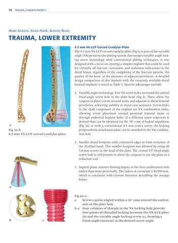
Trauma, lower extremity 4.5 mm VA-LCP Curved Condylar Plate The 4.5 mm VA-LCP curved condylar plate (Fig 1) is part of the variable angle (VA) periarticular plating system that merges variable angle locking screw technology with conventional plating techniques. It was designed with a focus on creating a simpler implant that could be used for virtually all fracture, nonunion, and malunion indications in the distal femur, regardless of the complexity of the fracture pattern, the quality of the bone, or the presence of adjacent prostheses. A detailed design comparison of this implant with the currently available distal femoral implants is noted in Table 1. Specific advantages include:
a
b
Fig 1a–b 4.5 mm VA-LCP curved condylar plate.
1. Variable angle technology. Five VA screw holes surround the central fixed-angle screw hole in the plate head (Fig 2). These allow the surgeon to place screws around stems and adjacent to distal femoral prostheses, achieving stability in worst-case scenarios. Screw holes in the shaft component of the implant are VA combination holes, allowing screw placement around proximal femoral stems or through endosteal implant holes. If a different screw trajectory is desired than can be obtained via the 30° cone of locked angulation (Fig 2a) or with a conventional 4.5 mm cortex screw, the locking periprosthetic attachment plate can be attached to the VA combination hole. 2. Smaller distal footprint with contoured edges to limit irritation of the iliotibial band. This smaller footprint was allowed by using all 5.0 mm screws in the head of the plate. The central 95° fixed-angle screw hole is still present to allow the surgeon to use the plate as a reduction tool. 3. Sagittal plane anterior bowing begins at the first combination hole rather than more proximally. The radius of curvature is R1100 mm, which is consistent with current literature describing the average femur.
a
b
c
Fig 2a–c a Screws can be angled within a 30° cone around the central axis of the plate hole. b–c Four columns of threads in the VA locking hole provide four points of threaded locking between the VA-LCP plate (b) and the variable angle locking screw (c), forming a fixed-angle construct at the desired screw angle.