Installation Guide Basic Installation Guidelines for VintageTM 6 Freestanding/Retaining Walls.

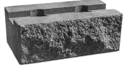
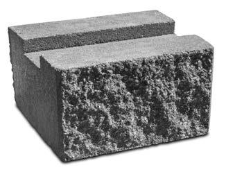
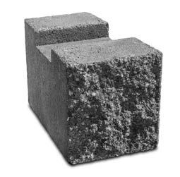
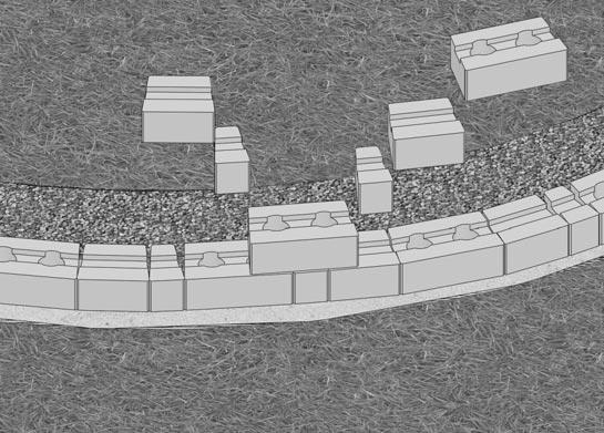
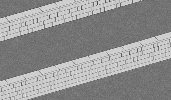
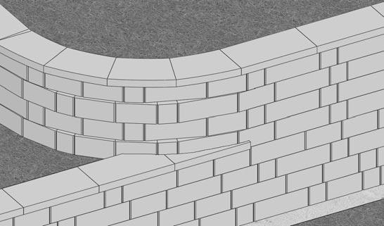
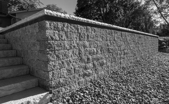
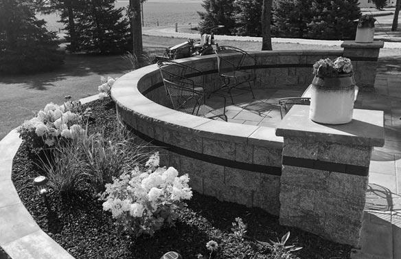
Vintage 6 is a three-piece, one-pallet wall system. Its double-sided split-face, anchor bar design builds strong and atheistically pleasing (straight or 8' radius) freestanding and retaining walls without the need for cutting. Use the three-sided split-face End Blocks to finish freestanding walls and two-sided split face Corner/Pillar Blocks for right angles and column construction.
Please note: Unit specifications, availability, color, and fascia options vary by manufacturer. Contact your nearest Rockwood manufacturer or dealer for availability and more information.
www.rockwoodwalls.com • (507) 529-2871
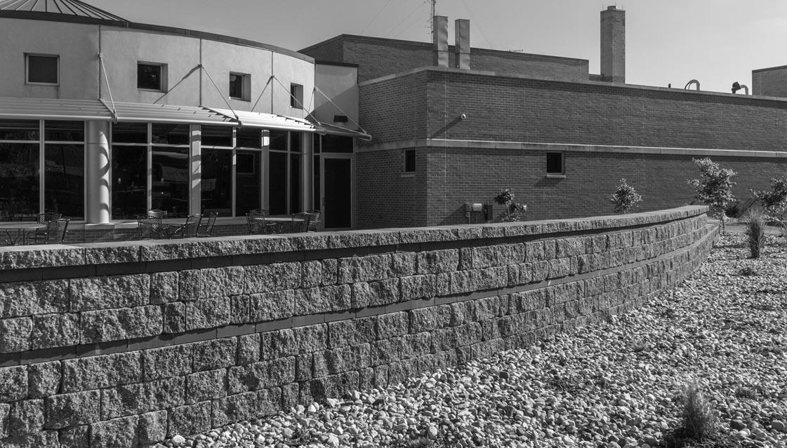
There is a significant difference in the planning and construction of retaining walls depending on their purpose. Typically walls under 4' in height are referred to as “non-critical” wall structures. Depending on the local, state and municipality requirements, walls under 4' in height may not require special review or permitting. Walls taller than 4' or any wall with a surcharge loading behind it (ie. sidewalk, driveway, building structure) should be evaluated by a qualified engineer.
Before you plan your project, learn about the necessary zoning requirements and rules for excavating and building in your area. No matter how small your project, be sure you obtain the necessary permits before you start construction.
Know What’s Below!
Whether you are planning to do it yourself or hire a professional, smart digging means calling 811 before each job. Homeowners often make risky assumptions about whether or not they should get their utility lines marked, but every digging job requires a call – even small projects like planting trees and shrubs.
Use the following methods to estimate the amount of base material, drainage rock, and adhesive you will need for your project.
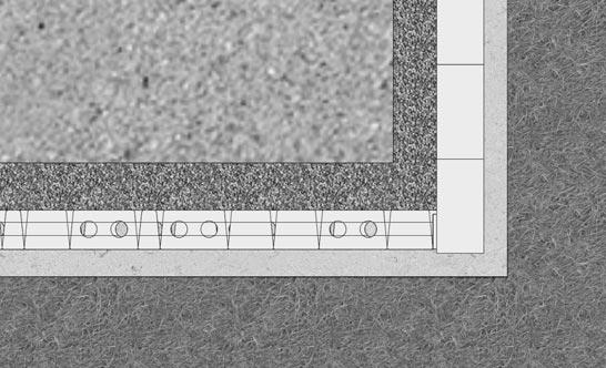
1. Base Material Needed
A typical trench is 2' wide and 14" deep to bury a full course of 8" block. Your base material must be a minimum of 6" in height.
*Add
for inconsistencies in the trench and compaction.
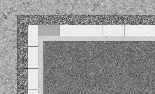
You need enough drainage rock to fill 1' behind the tail of the block and to fill any cores.
3.
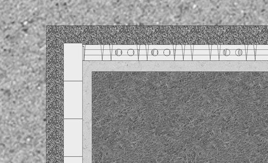
The amount of glue required depends on type of block and construction. Use the guide below to estimate the amount of adhesive required.
Approximate length of bead by bead diameter:
Professionals depend on Super-Stik™ adhesive for its superior strength, time-tested performance and versatility. Super-Stik is the ideal solution for segmental retaining walls, pavers, stone and masonry. You can even apply it to damp surfaces!
Especially formulated for:
• Use on damp or frozen surfaces
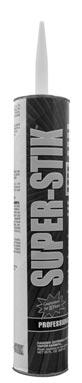
• Superior strength and stability
• Works well in extreme temperatures
• Waterproof bond
Note: Vintage 6 Garden Walls may be built to a maximum total height of 36" (under ideal conditions) without geogrid. Use a minimum 6" embedment and 12" of clean crushed rock behind wall.
When building under 3 ft. in height, place and compact a minimum of 6" base material to 95% Standard Proctor. Verify the base is level with a transit or hand level. Be aware the base material (commonly referred to as road base or base aggregate) will vary from region to region.
When using Vintage in retaining wall applications over 3 ft. in height, it is recommended to build on a 2 degree inclined base. This will increase wall batter and stability.
Simply place 1" of material on top of your compacted leveling pad. Screed the excess material away using a level tied to an angled board, compact to 95% std. proctor.
Walls 36" and above need to be built with geosynthetic reinforcement and may need to be designed by a licensed engineer.
Beginning at a point of the wall’s lowest elevation, excavate a trench down the length of the wall that will accommodate at least 6" of base material and 6" of block embedment. As a rule of thumb, for every 8" to 10" of wall height, 1" of block should be buried with at least a minimum of 6" base course embedment. Step the trench up or down with respect to adjacent grade.
The width of the trench for a Vintage 6 unit should be a minimum of 24". Based on the type of application and what is retained, the depth of the leveling pad may vary. If necessary, consult with an engineer.
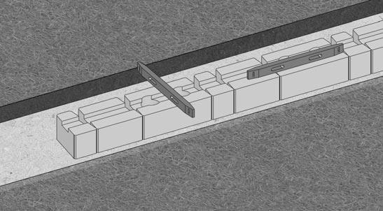
After excavating the native soil and prior to adding base material, remove loose material from the trench and compact.
Place and compact a minimum of 6" base material to 95% Standard Proctor. Verify that the base is level with a transit or hand level. Be aware that the base material (commonly referred to as road base or base aggregate) will vary from region to region.
PLEASE NOTE: Garden walls designs above 36" and retaining walls of any height that support a load should be evaluated and approved by a qualified professional engineer.
The base course will consist of base block. Use a string line behind the tail of the block for alignment on straight wall applications. All blocks should rest firmly on the pad and be centered to allow 6" of base material in front and 6" behind the Base Block. Level each block, side-to-side, front-to-back and across three full blocks with a hand level. A rubber mallet may be used to level and align the blocks.
Place 3/4" to 1" clean fill (crushed rock) within the cores and a minimum of 12" behind the blocks. This creates a drainage zone and Stone Columns that help to unify and maximize the performance of the wall.
Prior to adding successive courses, the top of each block needs to be clean and free of foreign material. Center the block and pull it forward until the Anchor Bar abuts the two blocks below it. Place core and drainage fill as in Step 4. Place the backfill material behind the drainage rock in maximum of 8" lifts and compact to 95% Standard Proctor. Repeat this process for each successive course.
Large compaction and construction equipment should be kept a minimum of 3' from the back of the wall. This 3' area should be compacted with a vibrating plate compactor.
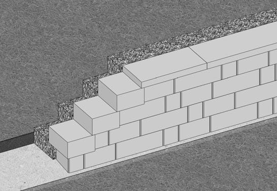
Step 6 - Capping a Wall
Use a full size cap to finish your wall, cut the cap adjacent for fit (matching any overhang). Secure with adhesive.
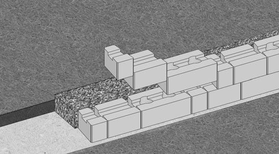
Step 7 - Ending a Wall
Step the end of your exposed wall with Vintage 6 corner block. Secure with adhesive.
While the installation steps presented are applicable to most basic wall designs, special consideration needs to be given to those applications in which a slope, surcharge loading, and/or less than ideal soils are present. These types of applications may require geosynthetic reinforcement or other engineering design support. Such applications include, but are not limited to:
• Wall Height
• Tiered Wall
• Driveways and Roads
• Bridges and Culverts
• Fences and Guardrails
• Water Applications
• Drainage
• Structures
Please refer to the geosynthetic reinforcement section for more information in regard to the incorporation of geosynthetic reinforcement in wall design.
Whether you are a seasoned professional or a weekend warrior, there is an ever growing on-line resource for designing, planning and building retaining walls and outdoor living spaces.
Visit us on the web at: www.rockwoodwalls.com
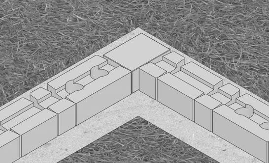
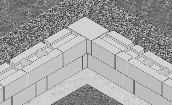
Established your corner location, and build out from the corner.
Vintage Wall units are designed to create a random stone appearance. However, care should be taken to avoid a “stacked bond” or vertical seams in the wall. To finish corner courses, any cuts should be made to the last block - not to the corner block. Measure the distance from the last block set to the corner and cut the block as necessary. Use Super-Stik construction adhesive to secure all corner and cut units.
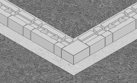
Using a hammer and chisel, score and split a Universal Cap 4" from one side. Position it on the corner with 1" to 2" of overhang. Cut another Universal Cap to be placed on the adjacent corner wall so that it is flush with the other cap unit. Secure Universal Caps with Super-Stik.
Begin an inside corner from the corner of the wall and install the blocks from the corner out when possible. Only half of a whole block installed on the corner will be exposed. This is true of each successive block that is staggered in the corner.
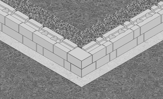
Vintage Wall units are designed to create a random stone appearance. However, care should be taken to avoid a “stacked bond” or vertical seams in the wall. To finish corner courses, any cuts should be made to the last block - not to the corner block. Measure the distance from the last block set to the corner and cut the block as necessary. Use Super-Stik construction adhesive to secure all corner and cut units.
Using a hammer and chisel or a masonry saw, cut a Universal Cap so it is perpendicular to the wall face. Cut the next Universal Cap to be flush with the corner cap. Secure Universal Caps with Super-Stik.
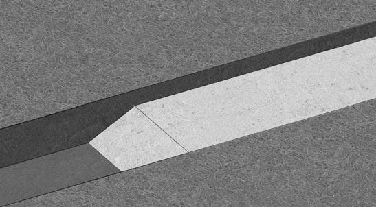
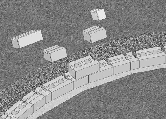
Step 1 - Base Course Preparation for a Convex or Concave Curve
Place the blocks on the leveling pad so there are no gaps between them.
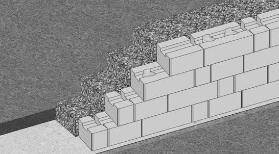
Step 2 - Successive Course Installation for a Convex or Concave Curve
When building multiple courses on a curve, begin installation by placing a block in the middle of the curve and centering it on two blocks directly below it. Build the wall from the center block outward.
CAPPING A WALL Shown with typical 3" or 4" tall rectangle cap block. See your manufacturer or distributor for available cap styles.
Geosynthetic reinforcement is an engineered product that is typically comprised of polypropylene, polyester, or other high-tensile material. Used in conjunction with segmental retaining wall blocks, it helps stabilize the soil mass behind a wall. Depending on the wall design, the length and the number of grid layers will vary.


Generally, grid strength is in the roll direction. As it is unrolled, it is in the same direction it should be installed. Biaxial grid is another option in which the strength is the same against roll direction as it is in the roll direction.
The area behind the wall on the grid layer needs to be level with the top of the block and to 95% of the Standard Proctor (ASTM D698).
Place the grid as close to the face of the wall without exposing it after successive placement of blocks. Ensure the grid is placed with the strength direction perpendicular to the wall. Check grid manufacturer specifications for proper grid placement instructions.

Place the next course of block. Pull the grid back and stake it so it is taut and free of wrinkles.
Place 3/4" to 1" clean fill (crushed rock) within the cores and a minimum of 12" behind the blocks. Place and compact backfill on the grid in lifts no greater than 8". When possible, it is recommended the backfill is deposited directly behind the wall and pushed to the end of the grid to ensure it remains taut and wrinkle-free.
Place grid following the contour of the curve.
Overlapping layers of grid on a convex curve require a minimum of 3" of fill between them for proper anchorage. Repeat these steps for successive specified grid layers.
Making sure the strength direction of the grid is perpendicular to the wall face, align the cut grid sections so they follow the contour of the concave curve. Grid layers should not overlap. An engineer will specify grid lengths.
After the next course of block is placed, lay the grid to cover the area of unreinforced soil below. This will ensure 100% coverage. Repeat these steps for successive specified grid layers.
On an 90˚ corner, it is important that grid layers do not overlap at the corner. Place the first grid layer per plan at its design elevation and length.


In the corner and on the next course of blocks, place a layer of grid perpendicular to the previous layer of grid. Repeat these steps for successive specified grid layers.

Branched walls require a minimum of one course embedment, as if each wall is independent.


Tiered walls may be installed where it is desirable or atheistically pleasing to use more than one wall. Upper walls can exert surcharge loads on lower walls. In order to design tiered walls independently, the walls must be set back a distance of at least twice the height of the lower walls. Whenever tiered walls are constructed, a qualified soils engineer should be consulted.
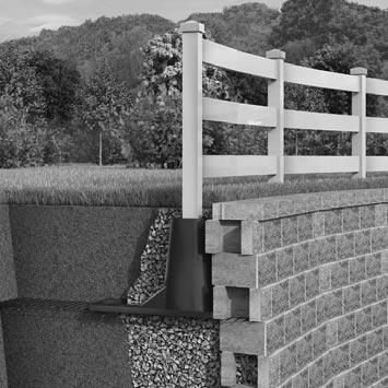
Special consideration must be taken when designing a retaining walls that includes fence or guardrail posts.
Sleeve-It is a proven system that uses a traditional cantilever design to engage the overlying soil mass,thereby providing resistance to the fence load. Sleeves should be installed as the wall is constructed. In reinforced walls, geogrid will need to be cut to fit around the Sleeve-It. Consult with an engineer in regard to design and application.

The above design tables were determined using the following assumed soil parameters and conditions: - Unit weight (γ)=120pcf for all soil types. - Friction angles (
A final site specific design should be evaluated and approved by a qualified professional engineer.
3' Wall (6 Courses)
3.5' Wall (7 Courses)
4' Wall (8 Courses)
5' Wall (10 Courses)
6' Wall (12 Courses)
The above design tables were determined using the following assumed soil parameters and conditions:
- Unit weight (γ)=120pcf for all soil types.
- Friction angles (φ); (φ)=32 degrees for Silty Coarse Sand (SM). (φ)=28 degrees for Silty Sand/Sandy Silt (SM-ML). (φ)=24 degrees Clayey Silt/Silty Clay (ML-CL).
- Designs assume a 6" compacted angular aggregate base (road base) leveling pad and swale directly behind wall. Rockwood’s design charts are for preliminary use only
A final site specific design should be evaluated and approved by a qualified professional engineer.
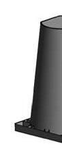
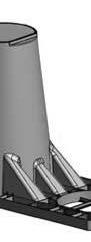
What is the Anchor Bar?
The Anchor Bar is a 4" x 4" x 5/8" projection on the bottom of the block that is laid against the backside of the face of the two blocks below.
What is backfill?
Backfill is the material placed behind the drainage zone that has been removed and replaced during the construction process. It needs to be compacted back to 95% Standard Proctor.
What is the base material?
The leveling material used to distribute the weight of the blocks over a wider foundation and to provide a working surface during construction. Base materials are composed of coarse-grained material ranging in size from fine sand to 1" aggregate.
What is batter?
Batter is the angle at which the face of the wall is from being vertical.
What is clay?
Clay is a fine-grained soil that typically possesses both plasticity and cohesiveness. It is considered a poor soil for construction purposes.
What is compaction?
Compaction is the densification of soils by means of mechanical action with equipment such as a plate compactor, jumping jack or hand tamper. Compaction is the most fundamental element in wall construction.
What is drain tile?
Drain tile is perforated pipe placed in the backfill and used to transport water away from the wall. Drain tiles are typically 4" perforated PVC pipe.
What is a drainage zone?
The drainage zone helps alleviate hydrostatic pressure at the back of the block. 3/4" to 1" clean fill (crushed rock) is placed a minimum of 12" directly behind the blocks.
What is an expansion joint?
An expansion joint is a space which allows for expansion as to not adversely effect an adjacent structure.
What are fines?
Fines are fine-grained soils, such as clay or silt.
What is Friction Angle?
It is an angle that describes the rate at which a soils’ strength increases under loading. The greater the friction angle of a soil, the lesser the lateral loads on a wall.
What is geosynthetic reinforcement?
Typically known as geogrid, it is a high tensile polypropylene or polyester material that helps stabilize the soil mass behind the wall. The number of grid layers and grid lengths are determined by a number of variables; including wall height, type of soil, etc.
What is filter fabric?
It is a geotextile used to filter fines from water. It is commonly placed between the topsoil and the backfill and drainage zones to eliminate the migration of soils into the drainage zone and to help prevent wall face staining.
What is grade?
Grade is considered to be ground level.
What is a gravity wall?
A gravity wall is able to resist soil pressure by relying only on its mass. This type of wall does not require geosynthetic reinforcement.
What is hydrostatic pressure?
It is the pressure exerted on the back of a wall by water in undrained or saturated soils.
What is a leveling pad?
The level surface (gravel or concrete) used to distribute the weight of the stacked blocks over a wider foundation area and to provide a working surface during construction. The leveling pad is typically constructed with granular soil to facilitate compaction.
What is retained soil?
It is the soil, excluding backfill, which is retained by the wall.
What is silt?
Silt is a fine-grained soil.
What is a Stone Column?
It is a continuous vertical column of clean fill material that is formed when the Rockwood block cores are filled. The Stone Column unifies grid and block into an integrated structural system.
What is surcharge loading?
It is a force exerted at the top of wall such as loading from a slope, roadway, parking lot, or building. Surcharge loading should be considered in the design of a wall.
What is a swale?
A ditch or canal used to divert water away from the back of the wall.
Be sure you have Rockwood’s engineers create a Prelim (Preliminary Material Quantity Take-off) before you bid commercial wall projects. Project Prelims using Rockwood products are done at no charge.
For engineering assistance, contact your regional Rockwood sales representative or call (507) 529-2871.