VALVE IDENTIFICATION
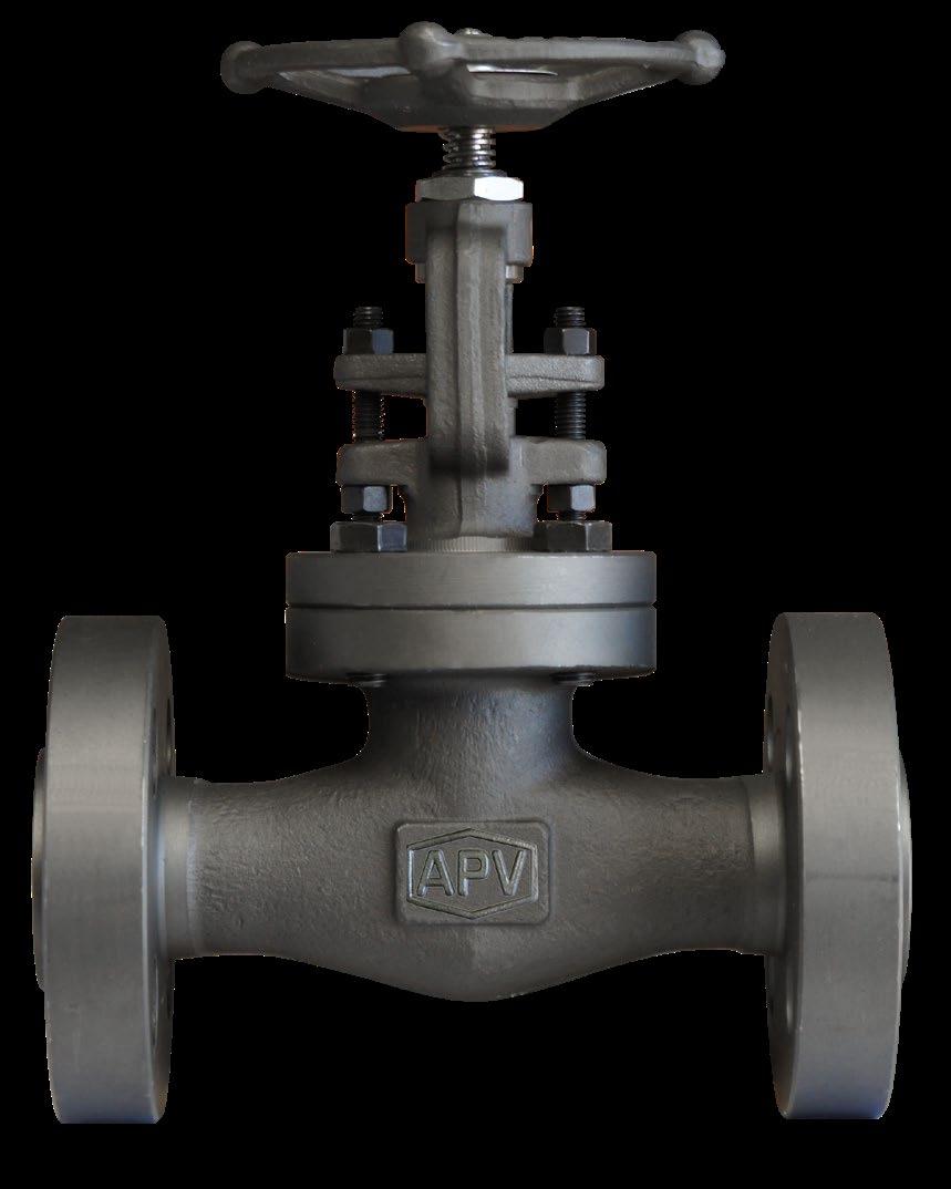
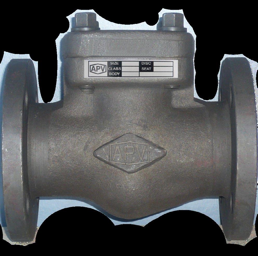
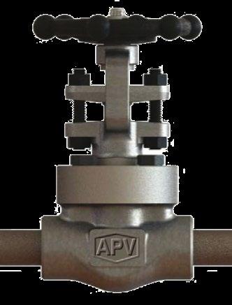
Each APV valve is identified with a nameplate, which is placed over the handwheel and secured with the hand wheel nut on gate and globe valves, and riveted to the cover on check valves. Below is an example.
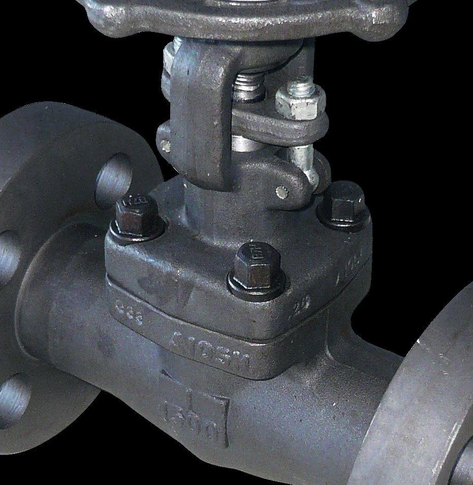
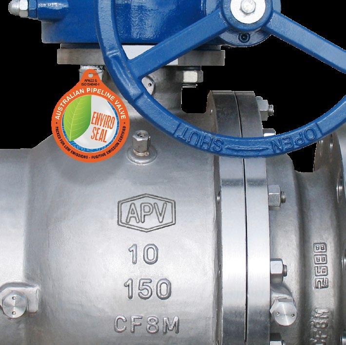
When performing any work, ordering spare parts, or requesting technical support, please refer to this tag. The serial number, the part number and numbers on the side of the valve body are keys to proper valve identification.
GLOBE VALVES OS & Y - FORGED - ISO 15761/API 602/B16.34 Australian Pipeline Valve - Installation, Operation and Maintenance Manual 6
TYPE CLASS BODY ENDS SIZE STEM PKG DISC GASKET SEAT CWP@38ºC MAX TEMP API 602 ASME B16.34 9 10 11 12 13 14 15 8 8 7 6 5 4 3 2 1 No. Figure Number Code Description 1 Serial number Serial/batch numbers 2 Type The as-built valve type 3 Body Material Shell material (e.g. body, bonnet) 4 Stem Stem material (e.g. A105, WCB, F51, CF8M, etc.) 5 Disc Closure member base material + overlay 6 Seat Seat base material (+ overlay if applicable) 7 MAX Temp. Maximum temperature 8 Standard Applicable design codes 9 Model number APV valve figure number which delineates the as-built valve type, body, trim, features, packing, NACE, etc. Refer figure number system in Appendix B 10 Class Rated pressure class 11 Ends End connections 12 Size Nominal pipe size 13 PKG Stem packing (e.g. GRP, GRPF, PTFE) 14 Gasket Bonnet gasket (e.g. SW316, 316 ring, PTFE) 15 CWP @ 38ºC Cold working pressure temperature * NACE MR0175 Identifies corrosion resistance * NACE is indicated by a separate NACE tag.
1.0 INSTALLATION
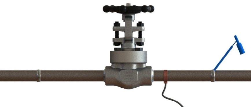
Piping should be properly aligned and supported to reduce mechanical loading on the end connections.
1.1 INSTALLATION POSITIONS
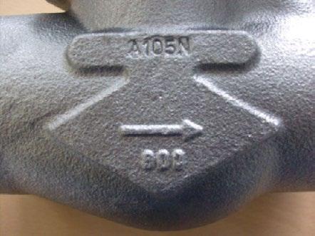
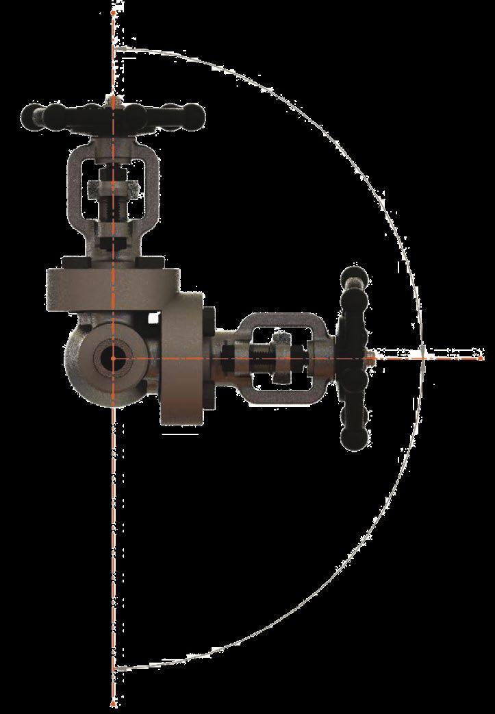
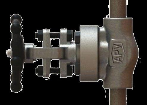
Globe valves are unidirectional and have the direction of flow indicated on the valve body. Globe valves should be installed with the stem in a vertical up position on horizontal lines. Other acceptable stem positions are at an angle between the vertical and horizontal axis which still allows for complete drainage. If installed with the stem below the horizontal axis, complete drainage is not possible and solids may accumulate in the valve bonnet, which will greatly affect the valve operation and service life. Globe valves may also be installed in vertical lines but this must be specified at time of order so the valve can be as-built and tested for vertical service. See Figure 1 for details.
Australian Pipeline Valve screw-down non-return globe valves are recommended for use in horizontal lines only. Right angle globe valves are recommended for vertical lines.
GLOBE VALVES OS & Y - FORGED - ISO 15761/API 602/B16.34 Australian Pipeline Valve - Installation, Operation and Maintenance Manual 7
VALVE POSITIONING
Line
Line Maximum Rotation NotAcceptable
FIGURE
1
Horizontal
Vertical
1.2 PREPARATION FOR INSTALLATION
• Remove protective end caps or plugs and inspect valve ends for damage to threads, socket weld bores or flange faces.
• Thoroughly clean adjacent piping system to remove any foreign material that could cause damage to seating surfaces during valve operation.
• Verify that the space available for installation is adequate to allow the valve to be installed and to be operated.
Note
Ensure sufficient clearance for the stem in the full open position may cause the valve to be inoperable. Inadequate clearance for valve may add mechanical loading to the valve ends. Sufficient clearance should be allowed for threaded valves to be ‘swung’ during installation.
1.3 END CONNECTIONS
1.3.1 Threaded Ends
Check condition of threads on mating pipe.
Apply joint compound to the male end of joint only. This will prevent compound from entering the valve flow path. Wrenches should be used on the valve end closest to the joint being tightened.
1.3.2 Flanged Ends
Check to see that companion flanges are dimensionally compatible with the flanges on the valve body and make sure sealing surfaces are free of dirt.
Install the proper studs and nuts for the application and place the flange gasket between the flange facings.
Stud nuts should be tightened in an opposing criss-cross pattern in equal increments to ensure even gasket compression. Refer Appendix A, Figure 10.
1.3.3 Socket weld Ends
Remove all, debris grease, oil, paint, etc., from the pipe that is to be welded into the valve and from the valve end connections.
Insert the pipe into the valve end connection until it bottoms out in the socket weld bore. Withdraw the pipe 1.59mm (1/16”) so that a gap remains between the pipe and the bottom of the socket weld bore to prevent cracks (ASME B1.11). Tack the pipe into the valve and complete the fillet weld.
GLOBE VALVES OS & Y - FORGED - ISO 15761/API 602/B16.34 Australian Pipeline Valve - Installation, Operation and Maintenance Manual 8
Globe valves should be lightly closed during welding to prevent damage to the seating surfaces and stem caused by thermal expansion during the weld process.
1.3.4 Buttweld Ends
In accordance with ASME B16.25 clean the weld ends as necessary and weld into the line using an approved weld procedure. Make sure the pipe and valve body material given on the nameplate or valve body is compatible with the welding procedure. (Refer our compatibility cross reference chart for equivalent pipe, valve & fitting grades).
1.3.5 Valve Installation by Welding
In accordance with ASME B16.11 unless the valve contains PTFE packing and/or gasket, leave valves assembled and in the lightly closed position during installation, welding and post-weld heat treatment. This will prevent the valve seat from floating or distorting during the process. After welding completion, open the valve and flush line to clean out any foreign matter.
Valves under 40mm (1 1/2”) containing PTFE packing and/or gasket must be dis-assembled for installation as the welding temperature can adversely affect the PTFE components. Remove the bonnet and bonnet gasket and match mark each component during disassembly for proper reassembly.
If you do not disassemble valves it will be the responsibility of the operator to ensure valves are kept cool during welding and then post-weld testing of the valve should be performed. Larger size valves over 65mm NB are less likely to transmit heat to bonnet and stem packing during welding but still care should be taken.
The responsibility for welding of the valves into piping systems is that of those performing the welding. Refer to ASME B31.1, B31.3 etc. Written welding procedures covering all attributes of the process and materials to be welded shall be in accordance with Section IX of the ASME Boiler and Pressure Vessel Code and any additional requirements from the applicable piping code including any possible necessary localized PWHT depending on material specifications.
APV forged globe valves do not run the risk of seat loosening during welding due to the fact that they are supplied with integral Stellite body seats.
Subsequent to welding, clean and inspect the finished weld(s) and, if necessary, repair any defects using a qualified weld repair procedure. In addition, cycle the valve open-closed to check for proper operation, making sure no binding has occurred due to the weld heat.
GLOBE VALVES OS & Y - FORGED - ISO 15761/API 602/B16.34 Australian Pipeline Valve - Installation, Operation and Maintenance Manual 9
Special trim options and body materials such as valves with PTFE packing/soft seat/special seals/ and gaskets that have maximum temperature limits less than the valve, may require special welding and heat treatment considerations which are not included herein.
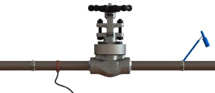
1.3.6 Post Weld Heat Treatment (PWHT)
The recommended method of PWHT is via local ceramic resistance heaters, individually monitored with thermocouples. Thermocouples are attached to the weld or welds. Properly sized ceramic heaters are wrapped around the weld area, extending approximately 6.35mm (1/4”) past the weld on the valve side. Do not wrap the valve body with a heating element. See Figure 1 for details. Wrap flexible insulation around valve ends, extending approximately 12.5mm (1/2”) past the valve on the valves side. It is not recommended to wrap the entire valve body with insulation. Prior to heat input close the valve completely, then open the valve approximately 1.58mm (1/16”) of a turn after the handwheel slack is run out. This very slight opening will allow the trim components to expand during the thermal cycle. Following PWHT, inspect the valve for smooth operation by cycling open and closed. If possible, perform a seat closure pressure test prior to service operation.

GLOBE VALVES OS & Y - FORGED - ISO 15761/API 602/B16.34 Australian Pipeline Valve - Installation, Operation and Maintenance Manual 10
INCORRECT Arcing can occur across close tolerance areas of valve due to ground strap location.
FIGURE 2
Strap Welding CORRECT Ground strap is positioned before the valve Welding WELD SET UP
Ground
Strap Ground
4 3 2 1 ITEM DESCRIPTION 1 THERMOCOUPLE 2 VALVE 3 FIBRE INSULATION 4 CERAMIC HEATERS POST WELD HEAT TREATMENT
FIGURE 3
APV does not make any recommendations in regards to the actual PWHT details of temperature and time. This work is not within the scope of APV. APV recommends that all applicable “Piping Code” requirements be considered.
For alloy steel valves or when welding specification or service conditions require field PWHT, the valve may be order with pipe nipples already welded and heat treated in the factory before valve assembly. The specified PWHT can then be performed in line without affecting the valve.
1.4 POST-INSTALLATION PROCEDURES
After installation, the line should be cleaned by flushing to remove any foreign material. When caustics are to be used to flush the line, additional flushing with clean water is required. The valve should be opened and closed after installation to ensure proper operating function.
With the line pressurised, check the valve end connections, body to bonnet/cover joints and stem packing area for leaks. The packing may have to be tightened to stop packing leakage.
2.0 OPERATION
Forged globe valves should not be used to throttle to openings less than 20% or else flow induced vibration/venturi effect will damage seat and disc. Because of the body’s labyrinth design, the globe valve causes a larger pressure drop than a gate valve. Because of this, the globe valve is an excellent device for regulation of flow in the moderate to full flow range.
Globe valves should not be left in the fully backseated position under normal operating conditions. The packing may dry out under these conditions and leak as the valve is closed. However, depending on media, size, class and valve age many operators choose to leave the valve fully backseated at all times. Even when doing so there will still be usually some minor leakage past the back seat.
A cool valve may leak through the gland when opened to hot fluid. Wait before tightening the packing as the problem may go away.
GLOBE VALVES OS & Y - FORGED - ISO 15761/API 602/B16.34 Australian Pipeline Valve - Installation, Operation and Maintenance Manual 11
3.0 MAINTENANCE
Proper safety equipment and apparel should be worn when preparing to service a valve. Observe the following general warnings:
• A valve is a pressurised mechanism containing energised fluids under pressure and consequently should be handled with appropriate care.
• Valve surface temperature may be dangerously too hot or too cold for skin contact.
• Upon disassembly, attention should be paid to the possibility of releasing dangerous and or ignitable accumulated fluids.
• Ensure adequate ventilation is available for service.
3.1 GLAND PACKING ADJUSTMENT
Tools Required: - aside from standard wrenches (for bonnet cap screws and packing gland nuts) the only tool needed for minor Australian Pipeline Valve valve maintenance is a packing hook.
Special care is to be placed in the tightening of the gland nuts during installation, in order to get the proper packing adjustment and functionality.
The packing gland should be checked periodically in service and tightened as necessary to stop leakage around the stem. Tighten in a manner to develop uniform loading on the gland. Tighten only enough to stop the leak.
GLOBE VALVES OS & Y - FORGED - ISO 15761/API 602/B16.34 Australian Pipeline Valve - Installation, Operation and Maintenance Manual 12
RIGHT WRONG
Over tightening will cause the packing to fail prematurely as well as increasing the force required to operate the valve. The packing gland flange should not bend even slightly, if it does you have over-tightened the valve and have to replace the flange.
If the leak cannot be stopped by tightening the gland nuts, it is necessary to add additional packing rings or completely repack the valve. Adding additional packing rings may damage the stem sealing system over a longer term. While most Australian Pipeline Valve globe valves are equipped with a back seat feature, it is NOT ALLOWED TO REPACK THEM UNDER PRESSURE. For fugitive emission service, proprietary fugitive emission packing must be used.
Note, PTFE packing has superior sealing properties compared to graphite, but is not firesafe. PTFE packing is only rated to 180°C maximum but PTFE pressure rating also down rates as temperature increases above 50°C.
When placing a new valve into service, Australian Pipeline Valve recommends a preliminary packing adjustment to verify proper packing load. Additionally, it is recommended that a Baseline Leakage Test be performed following installation, but prior to start-up.
During the packing life cycle, normal and routine maintenance of the packing arrangement must be administered. Normal cycle life may require packing gland nut adjustments. Torque values vary depending upon valve type, class, design, boltings, material and size. Tighten the gland packing nuts clockwise. Do not over tighten or the valve will become too tight to turn (see Section 4.2.1.)
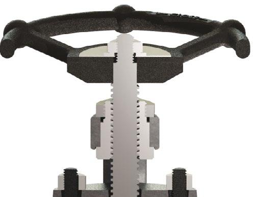
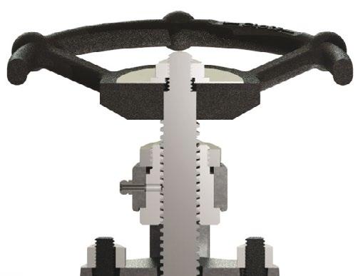
3.2 BACKSEATING
For normal operation in the open position, the stem should be backed off so that the backseat is not in contact. This permits the stem packing to assume it’s intended sealing function and not conceal unsatisfactory stem packing. In the event of stem packing leakage, the back seat can be used to stop stem leakage until circumstances permit a system shutdown and time for packing replacement. Stem packing replacement with the valve under pressure and backseated represents a hazard and should not be undertaken. The hazard is magnified as fluid pressure or temperature increases or when the fluid is toxic.
GLOBE VALVES OS & Y - FORGED - ISO 15761/API 602/B16.34 Australian Pipeline Valve - Installation, Operation and Maintenance Manual 13
Under no circumstances should the back seat be used to allow gland packing replacement or repair while the valve and system are pressurised.
One of the most common misunderstandings is to believe that is the Globe valve is back seated (fully open position - and backseat sealing made), this will help to prevent wear of the packing rings. Unfortunately using the back seat in this way over a longer period of time, could result in some serious issues:
a) Since the body, bonnet, stem and disc heat up and expand at different rates, experience shows that valve can get jammed/blocked in back-seated position.
b) The gland packing will dry out faster since it’s not exposed to the media, and could immediately blow upon closing of the valve.
To avoid this, once the valve is brought into fully open position (back seated), turn the handwheel back on full turn.
Prior to replacing the packing rings, remove all pressure from the valve.
WARNING: If the backseat faces have been damaged by foreign material the backseat may leak into the packing chamber.
3.3 PACKING REPLACEMENT
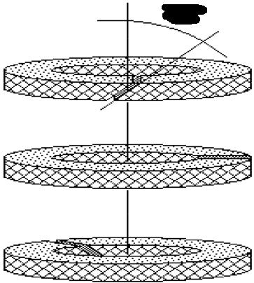
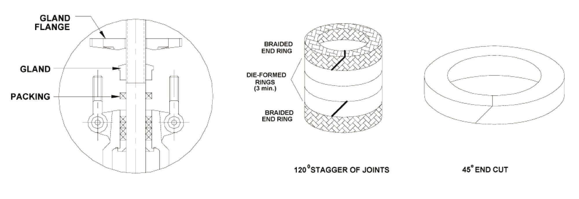
Ensure the line pressure is totally isolated prior to attempting to repack valve in-line. Wear anti-splash eye protection goggles. See Caution below, do not attempt to repack the valve in line if dangers noted applies as even if the valve is isolated there can be media trapped in the valve or line. Australian Pipeline Valve graphite or PTFE and graphite packing sets have a diagonal cut that will allow them to be installed around the stem of an assembled valve. However, the factory installed intermediate graphite packing rings are sometimes die formed and have no end cut. As a result, these rings cannot be replaced without removing the valve bonnet. If the valve is to be repacked without removing the bonnet, care must be taken when removing the original packing not to scratch the valve stem sealing surface. Where it is necessary to repack the valve in-line, a compatible ribbon packing system or equivalent braided packing stock should be used. The joints in the packing rings should be diagonally cut. When installing the rings, care should be taken to stagger the packing rings. See Figure 6. Refer to Section 4.2.1 for full packing replacement procedure.
In the case of dangerous, hazardous, volatile, caustic or flammable liquids or gases, it is dangerous to attempt to repack the valve in-line even if pressure has been isolated. Never attempt any metal scraping, scratching or machining which as this can cause inflammable liquids to ignite or personal chemical injury.
Other specialty packing such as V-ring Teflon may require that the valve be disassembled if repacking is required.
GLOBE VALVES OS & Y - FORGED - ISO 15761/API 602/B16.34 Australian Pipeline Valve - Installation, Operation and Maintenance Manual 14
Back seating the valve and attempting to repack under pressure is hazardous and is not allowed under any circumstances. Rather than attempting to repack under pressure, it is preferable to use the backseat to control the stem leakage until shutdown of the line provides safe repacking conditions.
Prior to replacing the packing rings, remove all pressure from the valve. If the backseat faces have been damaged by foreign material the backseat may leak into the packing chamber.
3.4 PREVENTATIVE MAINTENANCE AND PERIODIC INSPECTIONS
APV recommends that periodic inspections be carried out on all valves. The frequency of these inspections depends on the severity of the service and the frequency of the valve operation. As a minimum, all valves should be inspected quarterly to ensure proper operation and discourage the damage compounding effects of leakage. The following list details the specific valve types and areas requiring inspection and maintenance.
Item to Inspect Stop Check Globe
Check all lubrication points
Check body/bonnet join for leaks
Check for packing leaks
Check stem threads for wear
Ensure stem and seal areas are free from debris
If conditions permit, operate valve
Inspect all external connections
Inspect condition of actuator and/or gear operators (if applicable)
Inspect valve for obvious damage
Do not remove or loosen the packing gland or bonnet bolts while the valve is pressurised.
1. The valve stem packing should be inspected monthly. If the stem packing shows signs of leakage, simply tighten the adjusting nuts to compress the packing. Do not over tighten the adjusting nuts as this will make operation of the valve more difficult. If, after tightening the adjustments nuts to their fullest extent, the leakage does not stop, it is then necessary to replace the stem packing. It is not recommended that additional packing rings be added to the stuffing box as this may cause damage to the stem sealing system. For packing replacement see Section 3.3.
2. The lubrication of the yoke nuts should be inspected at least monthly. A high pressure grease gun should be used for valves supplied with ball type grease fittings.
GLOBE VALVES OS & Y - FORGED - ISO 15761/API 602/B16.34 Australian Pipeline Valve - Installation, Operation and Maintenance Manual 15
3. Bonnet bolt tension should be checked periodically when valves are used in high temperature applications where creep may occur. (see Tables A & B, Appendix A, and Figure 10). Although leaks through bonnet ring or spiral gaskets are rare, erosion or corrosion could cause bonnet seal to fail. In these cases, a new gasket is required. Refer Sections 4.3.1 & 4.3.2 for replacing bonnet gasket.
4. With problematic service applications it is recommended that the valve be periodically at least partially stroked to ensure valve functions and to ensure there is no product deposits entering into seat or stem area which may render operating more difficult. Duration depends on service, criticality, etc. However, it also must be factored in that if there are impurities or particulates in the line, likely to be built up in the seat area, each operation could reduce seat life proportionately.
3.5 LUBRICATION
Regular maintenance of the valve is required to assure smooth operation. Stem threads should be inspected and lubricated frequently to ensure ease of operation. APV valves are supplied with the stem threads engaging the yoke nut pre-greased. These components should be kept constantly lubricated by applying the grease directly on the stem when the valve is in the open position or through the grease injector in the yoke nut when provided. Lubrication/greasing of the stem should be conducted every six months or more often as needed, based on the environment the valve is installed. Inspection should confirm that the valve is sealing properly. Stem packing should be inspected at least every six months to ensure zero leakage from the packing chamber. For water & oil service, regular maintenance should be scheduled every 3 months. For more corrosive mediums, inspection and maintenance should be completed once a month.
3.6 BONNET BOLT TENSION
Bonnet bolt tension should be checked periodically when valves are used in high temperature applications where creep may occur. Although leaks through bonnet ring or spiral gaskets are rare, erosion or corrosion could cause bonnet seal to fail. In these cases, a new gasket is required. Refer Sections 4.3.1 & 4.3.2 for replacing bonnet gasket. Refer Appendix A, Tables A & B and Figure 10 for torque figures and tightening sequence.
3.7 PERIODIC STROKING
With problematic service applications it is recommended that the valve be periodically at least partially stroked to ensure valve functions and to ensure there is no product deposits entering into seat or stem area which may render operating more difficult. Duration depends on service, criticality, etc. However, it also must be factored in that if there are impurities or particulates in the line which are likely to be built up in the seat area, each operation could reduce seat life proportionately.
APV globe valves have one point of lubrication, the stem/yoke sleeve threads. Lubricate as follows:
- For APV globe valves with grease fitting, lubricate through the fitting.
- For APV globe valves without grease fitting, open the valve to half stroke.
- Brush lubricant on the stem threads above and below the yoke nut.
- Run a complete “open-close” cycle, the stem/yoke are now lubricated.
GLOBE VALVES OS & Y - FORGED - ISO 15761/API 602/B16.34 Australian Pipeline Valve - Installation, Operation and Maintenance Manual 16
4.0 EXTRAORDINARY REPAIRS & MAINTENANCE
Due to the relatively low replacement cost of small diameter standard carbon steel valves under, it is usually less expensive to replace the complete valve than to have maintenance personnel effect repairs. Generally, the only justifiable repairs are replacement of packing and gaskets as previously described.
Always replace the bonnet gasket whenever a valve is disassembled. ‘Pressure seal’ style bonnet valves (see example drawing Appendix C) require a proprietary gasket. After removing valve from line, use adequate force to remove bonnet. Gasket seating surfaces should be scraped clean (avoid radical marks). Bonnet bolts should be tightened in a diagonal pattern at several different increasing torque settings until the final recommended torque value is attained. Refer to Tables A & B in Appendix A, and Figure 10.
Other specialty packing such as V-ring Teflon will require that the valve be disassembled if repacking is required.
4.1 STEM
If the stem locks or “freezes”, causes can generally be attributed to dry worn packing or a dry yoke nut. In either of these cases, the following service is required:
a) Unscrew gland nuts, remove the gland flange and bushing to expose stem packing and packing spacer (where one is fitted). Replace stem packing if it is damaged.
b) Check lubrication of yoke nut. If it is dry, remove the yoke nut but determine if there is evidence of seizure marks. If so replace it with a new yoke nut.
4.2 GLAND DISASSEMBLY & REPLACEMENT OF STEM PACKING
In those cases where the valve cannot be removed from the piping system, it is important that prior to servicing, the valve be opened to its fullest extent and purged of any pressure/fluid (protective safety goggles should be worn).
a) Australian Pipeline Valve graphite or PTFE and graphite packing sets are usually die formed and have no end cut. As a result, these rings cannot be replaced without removing the valve bonnet. If the valve is to
GLOBE VALVES OS & Y - FORGED - ISO 15761/API 602/B16.34 Australian Pipeline Valve - Installation, Operation and Maintenance Manual 17 FIGURE 5 Lubrication Points
Globe Valve - Top Works (no grease fitting)
Globe Valve - Top Works (single grease fitting)
be repacked without removing the bonnet, care must be taken when removing the original packing not to scratch the valve stem sealing surface. For fugitive emission service, proprietary fugitive emission packing must be used.
Note, PTFE has superior sealing properties compared to graphite, but is not firesafe.
Genuine APV die formed moulded low friction PTFE or graphite packing sets are recommended. A compatible ribbon packing system or equivalent braided packing stock may be used but the emissions will be higher. Also torque may increase. A corrosion inhibitor is recommended for stuffing box.
b) Partially unscrew gland packing nuts to reduce the compression load on the stuffing box. Remove the stem packing.
c) Lift the gland flange/follower and gland out of the stuffing box.
d) Remove old packing as per Section 4.2.1 below.
e) APV fugitive emission graphite and PTFE packing has solid seal ring that must be cut for removal. Any remains of existing packing must be removed from the stuffing box and stem.
4.2.1 Stem Packing Replacement & Stem Repair
First remove the valve from the line. To prevent injury ensure that all fluid and pressure is removed from the valve both upstream and downstream before removal and disassembly. When removing drain or stem plugs, wear protective eye masks to avoid injury.
1. Check tightness of valve operation to serve as reference when re-tightening. Remove gland nuts and the hook. Lift the gland up the stem clear away from the packing chamber.
2. Remove the defective packing rings with a sharp tool or packing hook. Do not scratch or score the machined surfaces of the stem or packing chamber.
3. Examine the machined surfaces of the stem and packing chamber. Remove any scratches, scoring or burrs with an emery cloth or by hand filing. Clean the stem with a solvent soaked rag. Scratches to the stem and the packing chamber no deeper than 0.25mm (0.010”) can be removed by polishing the surface with a buffing wheel. The surface finish of the packing should be Ra 3.2µm and the stem should be Ra 0.5 ~ 0.8µm.
4. Count original number of rings and measure x-section thickness. If original packing cannot be counted or measured, follow the steps below:
a) Measure the stem diameter (OD), stuffing box diameter (ID) and stuffing box depth (d)
b) Packing x-section (R)=(ID - OD)/2
c) # rings = (1.25 x d)/R
5. Install new packing. Use a genuine APV low emission, low friction packing set. If using standard coils of packing material: cut each ring at a 45 degree angle and stagger the joints at 120 degrees, every fourth joint will be in the same position as the first. Install rings individually using a split ring spacer, compressing each ring by hand tightening + 1/4 turns on each packing gland nut.
6. Each ring should be firmly compressed into position before the next ring is added. Rings should fit
GLOBE VALVES OS & Y - FORGED - ISO 15761/API 602/B16.34 Australian Pipeline Valve - Installation, Operation and Maintenance Manual 18
snugly into the stuffing box; the ends of a packing ring must not overlap or remain open when fitted into the stuffing box.
7. When packing chamber becomes filled with packing, reassemble gland and gland flange. Alternate tightening packing gland flange nuts 1/4 turn at a time until eyebolts begin to get tight. (If gland travels more than the height of one packing ring into the packing chamber, insert one more ring and repeat step 6. until chamber is filled.)
8. Install the gland and the gland flange/follower, install the gland studs and nuts. Bolting lubrication is highly recommended to achieve adequate packing load. Tighten the nuts a few turns at a time to maintain a straight and level gland flange.
9. Compare valve operation to original tightness. If valve operation is considerably tighter than original operating tightness, back off 1/4 turn on each gland nut & recheck tightness. Where proprietary packing sets are used such as (example only) APV-Enviroseal M600, Garlock EVSP 9000, Burgmann 6070 or Chesterton 1622 please consult packing manufacturer’s torques. The serialised as-built drawing will indicate the packing used, please refer to APV. For Belleville spring energised gland packing bolts, refer to spring manufacturers torques. Also see Section 3.3 for more information on gland packing tightening. Various packing types, materials, proprietary combinations and styles with and without spacers/lantern rings, etc, and torque limitations of some bolting materials, bonnet design variations, stuffing box and stem smoothness, means it is not possible to safely publish recommended torques for packing. In addition, higher pressure ratings will require higher torques especially if media types are hazardous or more leak searching prone such as gas.
Note
We recommend using graphite packing with inbuilt lubrication such as APVEnviroseal M600 fugitive emission packing as adding grease to the bore can attract particles that damage the packing and the grease could cause product contamination. For an assured seal the only solution is to machine the stem and stuffing box smoothness as shown in figure 6.
10. Actuate the valve through a minimum of three (3) complete cycles ending with the valve in the closed position. Verify the torque provided for the valve being re-packed.
11. Several hours after a repacked valve has been returned to service, inspect the packing area to ensure full compression, tight bolting and no leakage. Should leakage occur, tighten gland nuts at 1/4 turn increments until leakage stops. The gland flange should not bend at all, if it does loosen and replace flange.
GLOBE VALVES OS & Y - FORGED - ISO 15761/API 602/B16.34 Australian Pipeline Valve - Installation, Operation and Maintenance Manual 19
45°
1 YOKE NUT
2 YOKE SLEEVE
3 STEM
4 GLAND NUT
5 GLAND FLANGE
6 GLAND BOLT STUD
7 PACKING GLAND
8 PACKING
9 BONNET
STEM PACKING*
*Example only, refer to as-built drawing. Die formed/moulded genuine APV packing set is required for fugitive emission service. Note
The stem packing style will vary according to valve size, type and class as well as the stem packing material specified. Examples include combination sets, wire reinforced braided packing, PTFE Chevron moulded sets, live loaded sets.
4.3 BONNET DISASSEMBLY & STEM REPLACEMENT/REPAIR
Before disassembly:
1. Check that the line is in a complete shut down phase then remove the valve from the line.
2. Pre-order all necessary spare gland packings and jointing gaskets.
3. Open the valve slightly by turning the handwheel anti-clockwise and loosen the gland.
4. Put identification marking on valve body, bonnet, disc, yoke and actuator. This helps to avoid mismatching of parts at the time of re-assembly.
5. If the bolts and nuts are too tight, apply deep penetrating oil then unscrew.
Refer Sections 4.3.1 & 4.3.2 for removing and replacing the bonnet & gasket.
To replace or repair the stem when the valve is completely disassembled for general maintenance first see Section 4.3.1 then follow this procedure:
• Open valve half way then remove bonnet bolts and nuts.
• Lift up the bonnet to remove disc. The disc has to be reassembled in the same position as originally assembled.
• Remove hand wheel then turn stem to release it from the yoke nut and remove from stuffing box.
• Check condition of back seat bushing for seizure marks. If apparent, order replacement parts.
• Remove stem packing.
• Remove stem. Remove disc from stem which may be threaded or keyed and may have a retaining clip or tack weld which can be removed.
GLOBE VALVES OS & Y - FORGED - ISO 15761/API 602/B16.34 Australian Pipeline Valve - Installation, Operation and Maintenance Manual 20
BRAIDED END RING DIE-FORMED RINGS BRAIDED END RING 45º 1 4 9 8 6 7 5 3 2 ITEM DESCRIPTION
FIGURE 6 FIGURE 6A
120° STAGGER OF JOINTS*
END CUT*
TYPICAL GLOBE VALVE (BOLTED BONNET DESIGN)
Welded bonnet valves can be replaced but otherwise are not repairable.
Always be sure that the valve is de-pressurised and isolated prior to performing any maintenance work. Do not attempt to repair valve in-line if volatile, dangerous, hazardous or flammable service. Note
• If seat & disc required relap see Sections 4.5 & 4.6.
• Then reassemble and test as per Sections 4.3.1 & 4.3.2 below.
4.3.1 Bolted Bonnet Removal & Gasket Replacement
Always replace the bonnet gasket whenever a valve is disassembled. Gasket sealing surface should be scraped clean (avoid radial marks).
1. Disassemble all cover bolts and nuts.
2. For larger valves (and in the case of higher pressure classes, in smaller sizes), lift up the bonnet using lifting lugs where provided. For smaller and lower class valves, gently and evenly break the bonnet seal with a lever if required before lifting the bonnet off (where required with a sling and mechanical lifting device).
3. Clean gasket surface areas, replace gasket and refit bonnet as detailed below.
4. Reassemble as per Section 4.8.
4.3.2 Pressure Seal Bonnet Removal & Gasket Replacement
In 900 to 2500 class a ‘pressure seal’ bonnet (see example drawing Appendix B) may be specified. The bonnet bolts or uni-bolt effect a seal on the pressure seal joint which forces the bonnet onto the gasket which in turn is forced up hard against the outer body. The higher the line pressure, the higher the sealing force against the gasket, further tightening the seal. The thrust rings are embedded in the body. Sometimes a ‘breech-lock’ threaded bonnet insert is used instead of a bolt energised bonnet, or a “uni-nut” system may be used. Refer to as-built drawing. Valves can be specified in conjunction with live loading bonnet bolt washers that can be tightened to ensure force is applied to the bonnet gasket.
GLOBE VALVES OS & Y - FORGED - ISO 15761/API 602/B16.34 Australian Pipeline Valve - Installation, Operation and Maintenance Manual 21
FIGURE
7
Bolted Bonnet (Spiral Wound Type)
Bolted Bonnet (Ring Type Joint)
Welded Bonnet (Full Penetration Welding)
Extended Bonnet (Full Penetration Welding)
Flexible custom made graphite or metal or combination gaskets may be used. Live loading bonnet bolt springs may be fitted which can be tightened to ensure a constant force is applied to the bonnet gasket. See sample drawing Appendix C.
Please refer to as-built drawing as APV has various styles of pressure seal designs.
The procedure to remove a pressure seal bonnet is as follows:
1. After disassembling the packing gland (refer Section 4.2) remove the bonnet bolts (or the threaded breech-lock bonnet or uni-nut).
2. Remove the segmented gasket.
3. Clean the gasket area and always fit a new gasket before reassembly.
Only an experienced valve repair professional should attempt repairs to pressure seal bonnet valves. There are different designs of pressure seal bonnet: - locknut type (breech lock), bonnet take-up type (bolted yoke arm) and the bolted style, hence, refer to as-built drawings. See Appendix C for for example.
4.4 BONNET REASSEMBLY
The procedure to reassemble the valve is as follows:
Re-insert the stem through the stuffing box taking special care to reassemble parts in sequence. If so equipped, avoid allowing the lantern ring to slide into the stuffing box. Next, insert the remaining packing rings into the stuffing box and compress using the gland and flange. Then, reassemble nuts and tighten.
Note, the stem must slide freely through the stuffing box without applying excessive force. Finally, install the bonnet gasket making sure it is not damaged. The gasket should be replaced if there is any question as to its performance (refer to Sections 4.3.1 & 4.3.2).
Raise the bonnet, making sure the stem is in the half open position, then connect disc to stem. Lower bonnet on to the valve body making sure that the disc fits exactly into body guides and the bonnet is properly seated. Align holes and tighten bonnet nuts taking care that excessive force is not used, to avoid damaging the gasket. Hydrostatically test the valve to ensure that there is no leakage.
4.5 DISASSEMBLY OF YOKE NUT
When necessary use the following procedure for disassembling and replacing yoke nut:
a) Direct hand operated valves (hand wheel)
• Remove set screw;
• Unscrew hand wheel nut;
• Remove hand wheel;
• Unscrew yoke nut retaining nut, removing spot welds if necessary.
GLOBE VALVES OS & Y - FORGED - ISO 15761/API 602/B16.34 Australian Pipeline Valve - Installation, Operation and Maintenance Manual 22
Reverse the procedure for reassembly.
b) Bevel gear operated valves
• To remove the bevel gear from the valve, unscrew nuts and turn the hand wheel in the open direction indicated by the arrow until the drive nuts are disengaged from the stem.
• To check the condition of the drive nut or bearing, unscrew the retainer ring and remove drive nut and bearing. If damaged, a new drive nut or bearing is necessary.
4.6 DISC AND SEATS
An indication of valve leakage is a pressure loss in the high pressure line side after a valve has been properly closed. In the case of hot water or steam lines, note whether the downstream pipe remains hot beyond the usual length of time. This type of leak may be the result of a distorted seat caused by improper welding of the valve into the pipeline or seating damage caused by foreign particle matter or by stress relieving temperatures that may have been used during installation.
Leaks can also develop from failure to close the valve tightly, resulting in high-velocity flow through a small opening. Trim materials such as F51/CR13 (410) and especially Stellite are corrosion and erosionresistant, but grooves, pit marks or other surface irregularities may still form on the mating surfaces. Valves which leak should be repaired as quickly as possible to prevent greater damage caused by high velocity. Leakage through seats and disc cannot be verified when valve is in service. However, when leaks are identified, immediate action is necessary. Any delay can permanently damage the seat or disc seal surfaces.
To repair or replace disc or seats, the valve must be removed from the line then use the following procedure:
• Make sure that the valve is not under pressure before unscrewing bonnet nuts.
• Remove bonnet, being careful not to damage the gasket. (Refer Section 4.3)
• Remove bonnet when disc is in half open position.
• Lift up bonnet until disc is disconnected from guides.
If seat surfaces show signs of seizing, pitting, grooves or other defects not deeper that 1.0mm (1/16”) it is possible to repair seating surfaces to its original condition by relapping the surface with line grain abrasive paste, creating a perfect tightness once again.
Defects having a depth exceeding .8mm (1/32”) cannot be repaired by lapping, in this case, parts must be replaced, or re-metallised or reground by an approved APV approved professional valve reconditioning service centre. Refer Section 4.7 below.
GLOBE VALVES OS & Y - FORGED - ISO 15761/API 602/B16.34 Australian Pipeline Valve - Installation, Operation and Maintenance Manual 23
It is recommended that the face of the disc be blued to check for contact of seating surface after final lapping. For re-assembly of valves use the procedure outlined under Section 4.7.
4.7 DISC & SEAT REPAIR
FIGURE 8
FORGED GLOBE VALVES OPTIONAL SEATING/DISC TYPES
Example only, refer to as-built drawing.
These valves are available with either threaded-in seat rings or an integral seat, both of which may be repaired (threaded in seats shall be replaced) while the valve is in line.
Globe valves require a guide fixture (refer to APV approved repairer) to maintain alignment during the lapping operation. The globe stem/disc assembly may be used in the lapping operation. However, due to its loose design, it is necessary to prevent the disc from rotating on the stem. After lapping it is recommended that the surface of the seat and disc be checked for proper contact using marking blue. Coat the seats with marking blue, and tightly screw the disc into seats. Unscrew the disc, and examine to make sure there is continuous contact between the sealing surfaces of the disc and body seat.
The lapping operation can be performed as follows:
a) Place a small quantity of lapping compound between the seat and disc surface.
b) With the lapping compound in place, between the mating surfaces, the disc should be reciprocally rotated: the strokes should be light, and the disc should be lifted frequently and turned to a new position, circularly around the valve body, so the lapping will take place over a new area.
c) Continue lapping until all defects are removed; apply a final finish with a fine lapping compound.
After lapping, it is recommended that the surface of the seat and disc be checked for proper contact using marking blue. Coat the seats with marking blue, and tightly screw the disc into the seats. Unscrew the disc, and examine to make sure there is continuous contact between the sealing surfaces of the disc and body seat.
4.8 VALVE REASSEMBLY & TEST
The procedure to reassemble the valve is as follows:
GLOBE VALVES OS & Y - FORGED - ISO 15761/API 602/B16.34 Australian Pipeline Valve - Installation, Operation and Maintenance Manual 24
Disc Washer Replaceable Disc Ring Screw Body Seat Overlay Stem Body Disc Gasket Body Disc Body Seat Elastomeric or Plastic Seat Insert Needle Point Metering Plug Flow Control Nozzle
Re-insert the stem through the stuffing box taking special care to reassemble parts in sequence. If so equipped, avoid allowing the lantern ring to slide into the stuffing box. If the valve is equipped with a lantern ring, first insert packing rings into the stuffing box followed by a lantern ring (where applicable). Next, insert the remaining packing rings into the stuffing box and compress using the gland and flange. Then, reassemble nuts and tighten.
Note, the stem must slide freely through the stuffing box without applying excessive force. The disc should be in the half open position.
1. Re-assemble in reverse order of disassembly of Sections 4.3 and 4.5.
2. Bonnet bolts should be tightened in a diagonal pattern increasing torque settings in accordance with the recommended torque value (see Tables A & B, Appendix A, and Figure 10). Avoid damaging gasket. Replace the gasket as per Sections 4.3.1 & 4.3.2 if damaged.
3. Test in accordance with API 598.
4. When performing a body test ensure the valve is in the open position but not in backseat position. Tighten gland packing only just enough to prevent leakage without needing to employ the backseat. In this way it can be proven the packing is performing it’s task. Over-tightening the packing gland will increase wear and tear of the packing and can damage the gland, gland bolts or stem. If the valve is tight to turn with ease, loosen the packing gland slightly. The backseating can also serve to determine if the valve stem or backseat itself is damaged by slightly loosening the packing gland nuts. Remember, compressed graphite packing rings will not initially be decompressed when the packing gland is loosened but they will leak. Always keep the valve in the backseat position when retightening the packing.
If there are indentations or pitting marks no deeper than 0.12mm (0.005”), a cast iron lapping disc with the proper seat angle must be used with a suitable lapping compound to roughen the surface first with the use of a new or refurbished original disc, use a fine lapping compound to final lap the disc and seat together.
Note, For body seat damage exceeding 0.12mm (0.005”) up to a maximum (for valve a seat angle of 30°), 1mm (0.040”) can be removed by grinding with the automatic grinding machines by an APV approved valve repairer. For major seat damage use 60 – 80 grit, diamond or micron Alumina stick on abrasive discs, and finish with fine grit 180 and up. For minor imperfections use medium coarse 120 grit stick on abrasive discs and finish with fine grit, 180 and up.
For the valve disc seating surface damage exceeding 0.12mm (0.005”), up to a maximum of 1mm (0.040”) can be removed in a lathe by an APV approved valve repairer (for disc with angle 27°).
GLOBE VALVES OS & Y - FORGED - ISO 15761/API 602/B16.34 Australian Pipeline Valve - Installation, Operation and Maintenance Manual 25
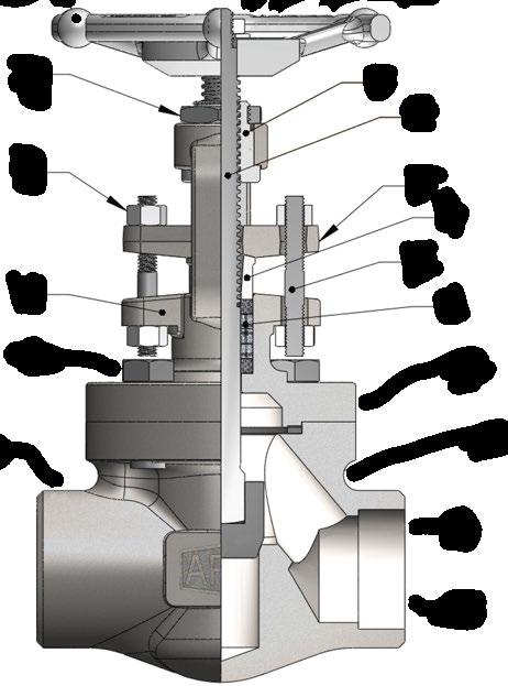
Typical Forged Bolted Bonnet Globe Valve Expanded View
1. Disc
Plug type disc is machined to the tightest tolerances to ensure trouble free shut off and cycling.
2. Disc Nut
The disc nut (where applicable) secures the disc to the stem. A tack weld or a lock ring may also be used.
3. Lock Groove
The lock groove attaches to the disc directly or a disc nut in some designs.
4. Stem
The stem insert vertically into the disc.
5 & 19. Gland Bolts & Nuts
The gland bolt and nut allows for easy adjustments for packing compression.
6. Stuffing box
The stuffing box contains the packing.
7. Stem Nut
The stem nut provides a precision guide for proper stem alignment.
8. Seat Ring
Can be separate or integral. Ensures a stable shut off, the seat ring is aligned into the valve, then precision ground for optimal seating.
9. Body
Forged steel bodies provide a low resistance flow and optimum strength and performance.
10. Bonnet Gasket
The bonnet gasket creates a leakproof seal between the bonnet and body.
11. Bonnet Bonnet assemblies are built to the same standards as the bodies.
12. Bonnet Bolts
The bonnet bolts secure the bonnet to the body.
13. Packing
The packing creates a seal above the back seat, between the bonnet and stem.
14. Gland
Compresses the packing to create a stem seal above the back seat, between the bonnet and stem.
15. Gland Flange
Applies pressure to the gland for accurate packing compression.
16. Handwheel
The handwheel cycles the valve.
17. Handwheel Washer
The washer helps to prevent loosening
18. Handwheel Nut
The handwheel nut secures the handwheel to the bonnet assembly.
*Example only refer to as built drawing as there are numerous designs for different sizes, classes, bonnet types & design standards.
GLOBE VALVES OS & Y - FORGED - ISO 15761/API 602/B16.34 Australian Pipeline Valve - Installation, Operation and Maintenance Manual 26
18 17 16 19 15 14 13 12 11 10 9 4 3 2 1 5 6 18 5 7 8
FIGURE 9