A JOURNAL OF MINING AND ENVIRONMENT
Vol. 28 Issue 1 / 2022 ISSN-L 1220-2053 / ISSN 2247-8590
Universitas Publishing Petroșani, Romania
REVISTA MINELOR - MINING REVUE A JOURNAL OF MINING AND ENVIRONMENT
Editorial board Editor in chief: Prof. Ilie ONICA Managing editors: Assoc.prof. Andrei ANDRAS Assoc.prof. Paul Dacian MARIAN Editorial advisory board: Prof. Dumitru FODOR Prof. Nicolae ILIAŞ Prof. Mircea GEORGESCU Prof. Pascu Mihai COLOJA Language editor: Lect. Lavinia HULEA Technical editor: Radu ION
ISSN-L 1220-2053 ISSN 2247-8590 www.upet.ro/revistaminelor www.sciendo.com/journal/MINRV
Scientific committee: Prof. Iosif ANDRAȘ, University of Petrosani, Romania PhD. Eng. Marwan AL HEIB, Ecole des mines de Nancy, INERIS, France Assist. prof. Adam BAJCAR, Poltegor-Instytut, Poland PhD. Eng. Iosif Horia BENDEA, Politechnico di Torino, Italy Assoc. prof. Boyko BEROV, Bulgarian Academy of Sciences, Bulgaria Prof. Essaid BILAL, Centre Sciences des Processus Industriels et Naturels (SPIN), France Prof. Lucian BOLUNDUȚ, University of Petrosani, Romania Prof. Ioan BUD, Technical University of Cluj-Napoca (North Center of Baia Mare), Romania Prof. Nam BUI, Hanoi University of Science and Technology, Vietnam PhD. Eng. Constantin Sorin BURIAN, INSEMEX Petrosani, Romania Prof. Eugen COZMA, University of Petrosani, Romania PhD. Eng. György DEÁK, National Institute for Research and Development in Environmental Protection Prof. Nicolae DIMA, University of Petrosani, Romania Prof. Carsten DREBENSTEDT, TU Bergakademie Freiberg, Germany Prof. Ioan DUMITRESCU, University of Petrosani, Romania PhD. Eng. George-Artur GĂMAN, INSEMEX Petrosani, Romania Prof. Ioan GÂF-DEAC, Dimitrie Cantemir Christian University Bucharest, Romania Ph.D. Eng. Edmond GOSKOLLI, National Agency of Natural Resources, Albania Prof. Andreea IONICĂ, University of Petrosani, Romania Prof. Sair KAHRAMAN, Hacettepe University, Turkey Prof. Sanda KRAUSZ, University of Petrosani, Romania Prof. Krzysztof KOTWICA, AGH University of Science and Technology Krakow, Poland Prof. Maria LAZAR, University of Petrosani, Romania Prof. Monica LEBA, University of Petrosani, Romania Prof. Roland MORARU, University of Petrosani, Romania PhD. Eng. Vlad Mihai PĂSCULESCU, INSEMEX Petrosani, Romania Prof. Sorin Mihai RADU, University of Petrosani, Romania Prof. Ilie ROTUNJANU, University of Petrosani, Romania Prof. Mihaela TODERAȘ, University of Petrosani, Romania Assoc. prof. Sorin Silviu UDUBAȘA, University of Bucharest, Romania Prof. Ioel VEREȘ, Technical University of Cluj-Napoca, Romania Assoc. prof. Zoltan Istvan VIRÁG, University of Miskolc, Hungary Prof. Florin Dumitru POPESCU, University of Petrosani, Romania
© Copyright by UNIVERSITAS Publishing House Petroşani / Revista Minelor - Mining Revue published quarterly Editorial contact: Ilie ONICA, e-mail: onicai2004@yahoo.com, phone: 0040 729 066 723 Dacian-Paul MARIAN, e-mail: dacianmarian@upet.ro, phone: 0040 748 130 633 University of Petroşani, 20 Universităţii str., 332006 Petroşani, Romania Phone +40254 / 542.580, fax. +40254 / 543.491 Printed by University of Petroşani Printing Department
Vol. 1 / 2022 ISSN-L 1220-2053 / ISSN 2247-8590
UNIVERSITAS PUBLISHING Petroșani, Romania
CONTENTS
Houssam KHELALFA, B. AYKAN, H. BOULMAALI Monitoring of tunnel rock mass deformations during provisional support stage: a case study
1
Izabela-Maria APOSTU, Constantin RADA, Maria LAZĂR, Florin FAUR, Nicolae SÎLI Investigation of the causes and factors generating land instability in the Berbești mining basin 24 Adina BUD Determinations and interpretations of heavy metal analysis in the sediments and water of Cavnic and Lăpuș rivers
37
Mykola STUPNIK, Olena KALINICHENKO, Mykhailo FEDKO, Mykhailo HRYSHCENKO, Vsevolod KALINICHENKO, Serhii CHUKHAREV, Sofiia YAKOVLEVA, Alexey POCHTAREV Study and enhancement of underground mining technologies to prevent earth's surface failures
42
Liliana ROMAN Water quality monitoring in Valea Jiului
50
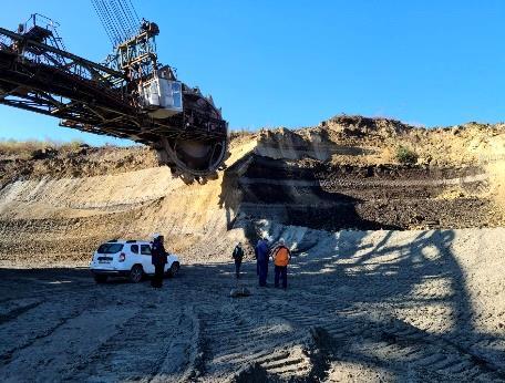
Ioan DUMITRESCU, Ciprian NIMARĂ Evaluation of air pollution as a result of coal exploitation in Roșiuța coal pit
66
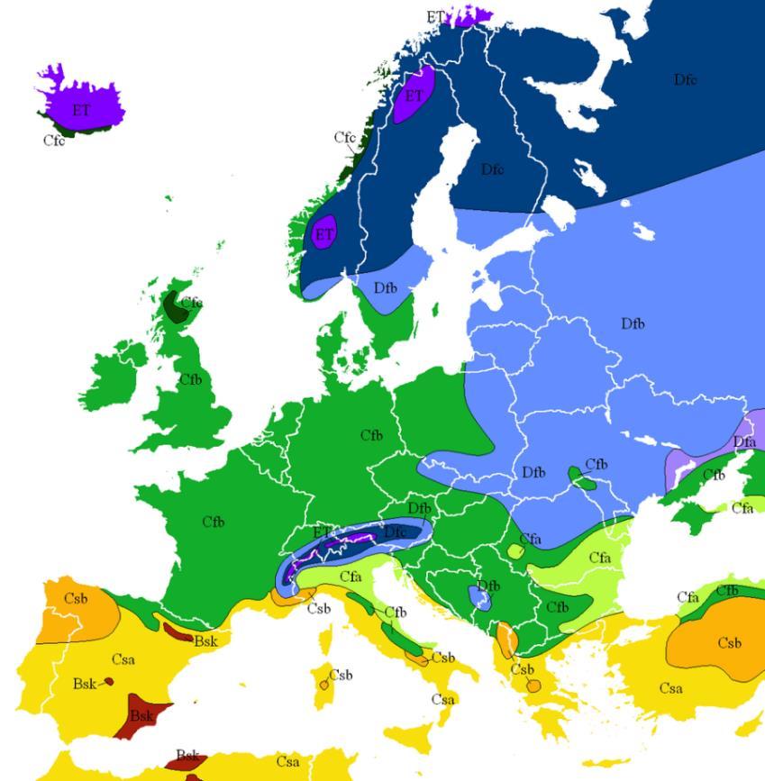
Alexandros I. THEOCHARIS, Ioannis E. ZEVGOLIS, Nikolaos C. KOUKOUZAS, Michal REHOR, Kristina VOLKOVA, David de PAZ, Pawel LABAJ, Michael BEDFORD, Małgorzata MARKOWSKA Past and present climate conditions of European coal and lignite areas
73
Revista Minelor – Mining Revue ISSN-L 1220-2053 / ISSN 2247-8590 vol. 28, issue 1 / 2022, pp. 1-23
MONITORING OF TUNNEL ROCK MASS DEFORMATIONS DURING PROVISIONAL SUPPORT STAGE: A CASE STUDY Houssam KHELALFA 1*, B. AYKAN2, H. BOULMAALI3 1
University of Jijel, Civil Engineering and Environment Laboratory (LGCE), Jijel, Algeria Selinus University of Science and Literature (SUSL), Faculty of Engineering and Technology, Bologna, Italy 2 MAPA İNŞAAT AŞ, Ankara, Turkey 3 CTTP, Kouba - Algiers, Algeria
DOI: 10.2478/minrv-2022-0001 Abstract: The present study evaluates on site the effects of provisional support on the rate of deformation (convergence) of clay-stone of a twin-tube tunnel. The combination of shotcrete, steel lattice, steel retaining, pre-supporting iron bar and Rock bolts can act as structural support in the form of provisional support for new or existing tunnels. Applications of provisional supports as confinement mechanisms to decrease the capacity of convergence can be helpful for distressed rock mass during tunnels digging. Real-size and realtime field monitoring over a period of approximately one (01) year was carried out with a Tachometer "Leica, TS 09" and 3D Displacement Monitoring Objectives fixed on the top heading and on the invert/bench. Wherefore; a sketch of the same cross-section of the tunnel was used in order to define the deformations of the rock mass of the tunnel measured in 3D in successive periods in all directions along the weak rock mass of the fourth class (IV) after the installation of the provisional support. The study shows good results in terms of deformation of the rock mass of the tunnel and satisfactory stability in terms of confinement. Consequently; it was noticed, that there is a relation between the deformations (convergence) in the two tubes along tunnel when the deformation of the left tube increases the deformation of the right tube decreases -, and that the deformation of the tunnel is a deformation overall of the rock mass and it is the same along the tunnel relative to its rock mass. It can be concluded that there is a reciprocal effect between the two tunnel tubes, which can be considered as a conservation principle of the rock mass. Keywords: Twin Tube Tunnel, Clay-Stone, Provisional Support, Deformations, Monitoring. 1. Introduction The soil deformations and the modifications created by the stresses of the soil during the digging of the tunnel are closely linked with the digging technique [1, 2]. The basic principle of tunneling with the new Austrian method is to have the rock transported by itself. Allowing the rock to deform slightly (as long as it remains within the admissible safety limits) considerably reduces the loads weighing on the load-bearing system. The rock released under control transfers the load to the sides and thus uses its transport capacity to the maximum by forming a transport chain around the excavation [3, 4, 5, 6, 7]. The three-dimensional support at the working face becomes two-dimensional as it moves away from the working face. Instead of carrying all the load of the rock, the support systems are instead used to control plastic deformation while maintaining the integrity of the transport chain around the excavation and avoiding excessive relaxations. Thus the flexibility of the system to the point of adapting to the rock deformations is one of the most important criteria of the method. If the rock is too weak to carry its own load, the support used stabilizes the system by providing additional pressure still needed to reach equilibrium after approaching rock carrying capacity [8, 9, 10]. The main feature of NATM is the application of support at the right time. In this case, it is accepted that there will be no load transfer on the coating concrete since the pressure from the ground is supported by the primary support system.
*
Corresponding author: Houssam Khelalfa, Assoc.Prof. PhD., Selinus University of Science and Literature (SUSL), Faculty of Engineering and Technology, Bologna, Italy, contact details (Tel.: +213697601497, khelalfahoussam@gmail.com, ORCID: 0000-0002-8052-6947) 1
Revista Minelor – Mining Revue ISSN-L 1220-2053 / ISSN 2247-8590
vol. 28, issue 1 / 2022 pp. 1-23
Tunnel ground deformation monitoring is the main means for selecting the appropriate methods of excavation and retaining from among those provided in the design to ensure the safety of the tunnel construction (including the safety of personnel in the tunnel and the safety of structures on the ground surface). The monitoring program includes the specification of the measurement procedure, the location of the monitoring devices and the monitoring schedule [11, 12, 13]. Attention is given to the fact that monitoring results are often affected by instrumentation, installation and environmental effects. The type of instrumentation chosen must ensure the following conditions: - A feasible installation procedure, - Sustainability during the monitoring period, - Protection against damage during construction, - Simple processing of measurements (acquisition and transmission of data), - Precision is required. In general, close readings of excavation activities are taken daily; the frequency is reduced with the distance to the forehead and the decrease of the displacement rates. Shorter monitoring intervals may be required due to the specific project requirements. Monitoring sections in tunnels and shafts are usually located at distances of 5 to 20 m depending on the conditions and requirements limits. A possible concept might display minimum reading frequencies and ranges for surface and underground monitoring for a summit-wings-bottom sequence. Usually, there are types of failure that cannot be detected in time by deformations monitoring, it is recommended to use additional monitoring of absolute displacements, but in a small extent. Thus the presence of an emergency surveillance system in case of adverse field conditions is ensured [14, 15]. In the case of block rock mass tunnels, the characteristic hazards are the detachments caused by the discontinuity of the blocks; therefore the observations must concentrate on the soil structure, the location and the orientation of the discontinuity with respect to the alignment of the tunnel. In the case of tunnels with moderate to high overload in the bedrock or foliar mass, the characteristic risks are; the orientation of the stratification or foliation, the displacement of the pavement, the displacements of the soil and the structure of the soil [16, 17, 18, 19]. Consequently, the observation focused on: visual inspections, laboratory tests, absolute displacement monitoring. 2. Geotechnical characteristics and geology of the project area The geological and geotechnical model of the tunnel is established using geological mapping and borehole investigation data. Six (06) boreholes in 2012-2013 and three (03) boreholes in 2015 are drilled in order to determine the structural and engineering characteristics of the geological units of the tunnel path and the state of the groundwater (figure 1) within the framework of a project in Algeria of a highway linked to the port of DjenDjen in Jijel province and El-eulma in Setif province. The path of the tunnel is located completely in the flysch made up of the alternation of mudstone and aged Albo-Aptian sandstone. The flysch is composed of mudstone which has a folded, weakly-moderately decomposed, weak-very weak rock nature and fine-grained sandstone which has a medium-thick, weakly decomposed, moderately solid-solid rock nature [20, 21]. The tunnel support systems can be modified depending on the geological and geotechnical conditions encountered [22, 23, 24]. The classification of rock masses on the tunnel path is determined according to RMR and Q System [25, 26, 27, 28, 29].
Figure 1. Location of the tunnel (red line) on an extract from the geological map of Tamesguida, between KP. 26 + 100 - KP. 26 + 650 (scale 1 / 50,000)
2
Revista Minelor – Mining Revue ISSN-L 1220-2053 / ISSN 2247-8590
vol. 28, issue 1 / 2022 pp. 1-23
The geological and geotechnical details of the tunnel route having been developed, the studies of 6 boreholes opened in the period 2012-2013 (FT-1, FT-2, FT-3, FT-4, FT-5 and FT-6) and of 3 boreholes opened in 2015 (SLT-01, S-LT-02 and S-LT-03) were evaluated in order to determine the engineering specifications of the units located in this part. The coordinates relating to the surveys carried out, the dimensions of the opening and their depths have been listed. As part of this work, three surveys in total were carried out; borehole numbers BH-26 at 50 meters deep on the left tube and borehole numbers TBH-1 at 80 meters deep on the left tube at PK 26 + 638 then borehole numbers TBH-2 at 50 meters deep on the coordinates 747372.526 (E), 4060873.833 (N), about 150m east of the passage of the valley which is located on the axis of the tunnel between PK 25 + 250 - PK 25 + 300, which are the upper elevations (+ 630m) from the same valley form a valley. The borehole number TBH-1 (figure 2), was carried out to analyze the thickness of its topography of the landslide and its influence on the tunnel identified between KP 24 + 955 - KP 25 + 125 on the axis of the tunnel (PK 25-030) and a landslide zone containing pieces of rock belonging to a flysch pile with the dimensions of fine-coarse gravel in a sandy clay matrix 21.50 m thick was identified. From 21.50 m up to 80 m which is the bottom of the bure, mudstone siltstone - alternating sandstone was discovered with a pile of flysch in the boring. These units are decomposed to a resistance of average low degree and of low-average resistance between 21.50 - 35.50 m and fresh little decomposition to a resistance of average degree after 35.50 m.
Figure 2. View of the decomposed new-low degree flysch units from the TBH-1 survey
As indicated in the geological context, the part is located (figure 3) between the entrance of the right tube of Texanna tunnel (in Jijel province) and PK: 24 + 840 and between the entrance of the left tube of Texanna tunnel and PK: 0 +761.82, tunnel level passes in the old Albo-Aptian Flysch unit.
Figure 3. Photo of the tunnel portal
3
Revista Minelor – Mining Revue ISSN-L 1220-2053 / ISSN 2247-8590
vol. 28, issue 1 / 2022 pp. 1-23
The geotechnical parameters were designated for the unit encountered in this part using data obtained from borehole S-LT-02 and borehole S-LT-01 located in this part of the tunnel. The evaluations carried out show that the unit located at the level of the tunnel is part of the "Low Rock IV" class according to the RMR classification. In addition, the KP: 24 + 840 part where the maximum coverage height is observed can be qualified as "critical part". The cross sections taken from part PK: 24 + 840 are shown below (figure 4). The design parameters of this part exposed above are summarized in table (1).
Figure 4. Inner cross section of twin-tube tunnel
3. Material and methodology 3.1. Excavation steps of low rock and monitoring In order to ensure the smooth progress of the tunnel digging, the opening of the gallery will be in halfsection. An upper half (calotte/ top heading), a half lower left and right (Strozze/Bench) and the bottom (invert). During each excavation phase, the topographic team will always be on site for the various controls. The station setup of the total station instrument can be done in two (02) methods; - The free station method consists in setting the station on a fictitious point located as close as possible to the vertical plane passing through the hanger and to orientate itself on a minimum of 02 terminals (bounds). - The setting up of the device on a known terminal and oriented on another terminal while avoiding the maximum tangential sights. Following the geological constraints of the soil and the eventual use of the explosives, the so-called "B" line of the actual excavation line will be lifted and checked in a contradictory way, this one allows the quantification of the excavated materials and the volumes of the shotcrete to put. If the rock is friable/ poor/ loose, the excavation is carried out by a machine that attacks the soil punctually and progressively. These self-propelled machines on wheels or tracks are equipped with adjustable arms, at the end of which is placed the attacking apparatus (excavating bucket, breaker, cutting head with longitudinal or transverse axis). The cuttings are evacuated towards the rear. The wall is equipped with the advancement of a temporary support. This technique is suitable for all excavation profiles. The excavation steps are as following (figure 5): - Excavations of the upper half (Top heading): • Excavations, • The surface will be coated with 7cm shotcrete, • Injection pre-support bars will be anchored (one (1) per each three (5) hanger, 4
Revista Minelor – Mining Revue ISSN-L 1220-2053 / ISSN 2247-8590 • • • • • •
vol. 28, issue 1 / 2022 pp. 1-23
The steel wire mesh will be implemented (Q589/443), Steel hanger will be set up (HEB 220), Shotcrete will be completed up to 29cm, The steel wire mesh will be implemented (Q589/443), The shotcrete will be completed up to 35cm, IBO bolts will be implemented.
Figure 5. (a)- Phase 1: Application of 3 “injection sinking pipes” to the cutting face in 30-40 cm intervals prior to excavation
Figure 5. (b)- Phase 2: Making an excavation along the recommended circle on the upper half, Application of a wire mesh (150 * 150 * 6.5 mm). HEB 220 steel cladding, Surface coating with 35 cm shotcrete, Temporary Slab, wire mesh and shotcrete casting and IBO bolt application 5
Revista Minelor – Mining Revue ISSN-L 1220-2053 / ISSN 2247-8590
vol. 28, issue 1 / 2022 pp. 1-23
- Excavations of the lower half (Bench): • Excavations in 2 steps, • The surface will be coated with 7cm shotcrete, • The steel wire mesh will be implemented (Q589/443), • Steel hanger will be set up (HEB 220), • Shotcrete will be completed up to 29cm, • The steel wire mesh will be implemented (Q589/443), • The shotcrete will be completed up to 35cm, • IBO bolts will be implemented.
Figure 5. (c)- Phase 3: Excavation along the recommended circle on the lower right-lateral half, Application of wire mesh (150 * 150 * 6.5 mm). HEB 220 steel cladding, Surface coating with 35 cm shotcrete, and IBO bolt application
Figure 5. (d)- Phase 4: Making an excavation along the recommended circle on the lower left-lateral half, Application of a wire mesh (150 * 150 * 6.5 mm). HEB 220 steel cladding, Surface coating with 35 cm shotcrete, and IBO bolt application
- Excavations of Bottom (Invert): • Excavations; Max. in 4 steps, • The surface will be coated with 7cm shotcrete, • The steel wire mesh will be implemented (Q589/443), • Steel hanger will be set up (HEB 220), • Shotcrete will be completed up to 29cm, • The steel wire mesh will be implemented (Q589/443), • The shotcrete will be completed up to 35cm, • IBO bolts will be implemented. • Backfilling.
6
Revista Minelor – Mining Revue ISSN-L 1220-2053 / ISSN 2247-8590
vol. 28, issue 1 / 2022 pp. 1-23
Figure 5. (e)- Phase 5: Execution of an excavation along the recommended circle on the base/ Slab, Application of a wire mesh (150 * 150 * 6.5 mm). HEB 220 steel cladding, Surface coating with 35 cm shotcrete, and IBO bolt application
Figure 5. (f)- Phase 6: final coating
As detailed above and in the geotechnical report, this part of the tunnel passes through weak (poor) rock conditions (IV). Supports planned for use in the analyses in this part of the tunnel and the characteristics of the tunnel are given in the table (1). Table 1. Geotechnical Design Parameters for Interval Right Tube Entrance Portal – KP:24+840 & Left Tube Entrance Portal –KP:0+761.682.
Rock Mass Parameters
Primary Support Parameters Total
Tunnel Radius r0
7.5 m
In-situ Stress P0
1.62 MPa
Young's Modulus of Rock Mass E
404 MPa
Poisson Ratio υ
0.3
Maximum support pressure Maximum support strain Installed at distance from tunnel face Initial tunnel convergence Initial wall displacement Longitudinal deformation profile Rock bolts Type Maximum support pressure Maximum support strain Rock bolt circumferential spacing Rock bolt longitudinal spacing Steel set Type Area Properties Section Depth Weight 7
1.791 MPa 0.2 % 1m 1.04 % 78.15 mm Vlachopoulos and Diederichs (2009) 34 mm Rock bolt 0.354 MPa 0.2 % 1m 1m Wide flange rib 216 mm2 9100 mm 71 kg/m
Revista Minelor – Mining Revue ISSN-L 1220-2053 / ISSN 2247-8590
Compressive Strength of Rock Mass σm
Friction Angle Ø
vol. 28, issue 1 / 2022 pp. 1-23
0.119 MPa
32°
Maximum support pressure Maximum support strain Steel set out-of-plane spacing Shotcrete Type Thickness UCS Properties Young's modulus Poisson ratio Maximum support pressure Maximum support strain
0.297 MPa 0.118 % 1m Custom 350 mm 25 MPa 30250 MPa 0.2 1.139 MPa 0.076 %
3.2. Monitoring methods of deformation inside the tunnel (convergence) 3.2.1 Fundamental principles of 3D monitoring of absolute displacements Over the past two decades, 3D monitoring of travel has become a common practice and, because of the high information content, has gradually replaced other techniques. Measurements are performed using a total station (tachometer) and objectives. Precise prism lenses as well as bi-reflex lenses (reflectors) are used and their spatial position in the overall coordinate system or project is determined. Discrete three-dimensional displacement measurements are performed by repeated measurements (usually on a daily basis). Since full monitoring cannot usually be performed from one position, an interconnected observation scheme is required, which is established using identical reference points (Figure 6-a). Stable reference points are differentiated from points that always move (Figure 6-b). Points with a defined maximum displacement rate (usually <1mm / month) can be used as reference points.
Figure 6. (a): Sketch of an interconnected free station method in the tunnel
8
Revista Minelor – Mining Revue ISSN-L 1220-2053 / ISSN 2247-8590
vol. 28, issue 1 / 2022 pp. 1-23
3.2.2. Requirements The principle of "free parking determined" is used to obtain the position of the instrument. The absolute position of all coordinate components of the marked measuring points shall be determined with an accuracy of +/- 1 mm (standard deviation) with respect to the neighboring measuring sections over the entire observation period. To achieve this accuracy, the following conditions must be met; - Distance between the instrument and the nearest reference point: 10 - 30 m. - Minimum distance to the reference point furthest: 90 m. - Maximum distance to monitoring points: 80 m. - Maximum distance between monitoring positions: 110 m. - Approximate use of the same instrument positions for consecutive readings. - Positioning the instrument on stable ground. - Initiate the nearest free parking and finish the most distant goals. - The movement measurement starts from the farthest lens. - Make connection observations approximately symmetrical to the tunnel axis. - Intermediate orientation measures and closure verification at selected reference points. - Perform zero reading immediately after lens installation (before the next excavation). - The measurement of all the points of a section (in the case of reading at zero in the bench, the summit objectives must also be measured). - Registration of weather conditions taken into account in the assessment. - Acclimation of the instrument to avoid deviations due to temperature change. The following sources of errors should be avoided; - Observations near the tunnel wall (minimum wall distance of 0.5 m to 1 m), - Measurement errors due to refraction (e.g. observation through or near heat sources), - Position of the instrument near the side/ lateral walls, - Observations in asymmetrical connection (see Figure 6-b), - Measurements in a very dusty environment or during severe vibrations (i.e. caused by machinery).
Figure 6. (b): Sketch of asymmetrical connection observations (to be avoided)
The surveyor must record and submit the following items after each measurement action: Measurement sequence system (relative to the measurement section or along the tunnel). Unmeasured points and indication of motive (destroyed, not visible, etc.). Significant displacements (measurement error, rapid increase in displacements); - Readings at zero, - Monitoring conditions (air quality, vibration, limited visibility, heat sources, etc.). 3.2.3 Tachometer An electronic total station (Figure 6-c) with an automatic recording unit with the following minimum details shall be used; - Measuring the horizontal angle: +/- 1’’ (0.3 mgon), - Measuring the vertical angle: +/- 1’’ (0.3 mgon), - Distance from measure: +/- (1 mm + 1.5 ppm).
9
Revista Minelor – Mining Revue ISSN-L 1220-2053 / ISSN 2247-8590
vol. 28, issue 1 / 2022 pp. 1-23
Figure 6. (c): Photograph of the Tachometer, e.g. "Leica, TS 09" of the tunnel underground monitoring
3.2.4. Objectives The lenses are installed on special bolts with an adapter (see Figure 6-d).
Figure 6. (d): Components of 3D Displacement Monitoring Objectives; Bi-reflex (1) and prism lens (2), bolt (3) with protective cap (4) and predetermined breaking point (5), mounting bolts (6 + 7) with adapter (8)
The minimum manufacturing accuracies required are as follows; - Adapter with breaking point: +/- 0.1 mm, - Triple prism lens: +/- 0,01 mm, - Bi-reflex lens: +/- 0.1 mm. Minimum repeatability required of readings; - Triple prism lens: +/- 0,1 mm, - Bi-reflex lens: +/- 0.3 mm. This precision applies to repeated readings when the orientation of the lenses is changed or the lenses / adapters are replaced. Figure (6-e) and Figure (6-f) show the common practice installation and protection of a bolt monitoring against damage in the shotcrete coatings. Monitoring bolt and protective cap are attached to wire mesh. During the project, the bolt must be covered appropriately. The bolt head must be recessed a minimum of 10 mm from the surface of the shotcrete coating.
Figure 6. (e): Sketch of the monitoring bolt unit mounted in the shotcrete liner. (f): Bolt and adapter with prism lens mounted in a niche 10
Revista Minelor – Mining Revue ISSN-L 1220-2053 / ISSN 2247-8590
vol. 28, issue 1 / 2022 pp. 1-23
3.2.5 Installation and measurement procedure To achieve maximum efficiency with the measured data and to ensure comparable measurement results, the following points should be observed during underground monitoring and surface monitoring; - A predefined break point must be provided between the bolt and the lens, to avoid damage caused by bolts. - Solid mounting of the bolt. - Protection against damage during the application of shotcrete. - Existing installations must be taken into account when positioning objectives to ensure observations of the tachometer. - In the case of surface objectives, the foundations must be integrated under the frost or permafrost zone. - For surface objectives, the height of the objective above the ground must be between 50 and 100 cm. - (Refraction influence). 3.2.6 Underground - The objectives of a monitoring station must be; - Install immediately behind the front of the last turn and zero reading taken without delay; the maximum deviations from the planned installation of the station +/- 1 m are acceptable. - Install in the same position as those of the previous phases of construction, that is to say sum, bench (tolerance +/- 1 m). - Install at the same station as surface surveillance points (tolerance +/- 1 m). - Concurrent registration of the construction phase (for example, face positions) and exact assignment to measurements; - The position of the front is determined by the average value of at least three measures of the position of the front (figure 6-g). - The position of the forehead can be determined without a objectives (precision + - 10 cm). - The new front position is valid as soon as more than 25% of the face is excavated.
Figure 6. (g): Determination of the frontal position
4. Results and discussions It was observed in the whole of the rock mass of left tube of the tunnel on the kelomitric point KP. 2,501 (figure 7-a) during a period of 330 days; a total deformation of 4 mm at the Left Waist (it is a punctual deformation which is not distributed towards the different directions), a total deformation of 23 mm at the Left Shoulder (a descending deformation distributes most to the front and some may to the left and to the right), a total deformation of 71 mm at the Crown (a descending deformation distributing most towards the left and a little towards the front), a total deformation of 134 mm at the Right Shoulder (a descending deformation distributing completely towards the front) and a total deformation of 5 mm at the Right Waist (it is a punctual deformation which is not distributed towards the different directions). Also, what remarkable; is that the minimum deformation is located in the waists, and that the maximum deformation is in the Right Shoulder (exactly in the "Crown-Right Shoulder" line on the upper right side of the tunnel's tube), followed by the deformation on the Crown and on the Left Shoulder respectively.
11
Revista Minelor – Mining Revue ISSN-L 1220-2053 / ISSN 2247-8590
vol. 28, issue 1 / 2022 pp. 1-23
Figure 7. (a): Left tube Tunnel Cross section KP 2,501.000/ First measure: 15.05.-2017, Last measure: 7.04.2018
Afterwards, on the kelomitric point KP. 2,516 (figure 7-b) during a period of 427 days; a total deformation of 5 mm at the Left Waist (an almost punctual deformation with a small distribution to the right), a total deformation of 107 mm at the Left Shoulder (an ascending deformation distribute completely towards the right rear), a total deformation of 30 mm at the Crown (an ascending deformation mostly towards the right rear with a partial deformation directly towards the front), a total deformation of 44 mm at the Right Shoulder (a deformation distributed totally to the left in a half-dispersed way towards rear and front) and a total deformation of 25 mm at the Right Waist (a deformation distributed in a dispersed way in right and left halves towards the front). Also, what remarkable; is that there are significant deformations in all five (05) measuring points, and that the minimum deformation is located in the waists, and that the maximum deformation is in the Left Shoulder (exactly in the "Left Shoulder- Crown" line on the upper left side of the tunnel's tube), followed by the deformation on the Right Shoulder and on the Crown respectively.
Figure 7. (b): Left tube Tunnel Cross section KP 2,516.000/ First measure: 17.01.2017, Last measure: 21.03.2018 12
Revista Minelor – Mining Revue ISSN-L 1220-2053 / ISSN 2247-8590
vol. 28, issue 1 / 2022 pp. 1-23
Afterwards, on the kelomitric point KP. 2,541 (figure 7-c) during a period of 270 days; a total deformation of 4 mm at the Left Waist (a minor almost punctual deformation distributed in all directions in an equal way), a total deformation of 32 mm at the Left Shoulder (a descending deformation distributing almost completely towards the front), a total deformation of 48 mm at the Crown (a descending deformation distributing almost completely towards the front of the left side), a total deformation of 51 mm at the Right Shoulder (A descending deformation distributing almost totally to the left of the front) and a total deformation of 2 mm at the Right Waist (a minor almost punctual deformation distributed in all directions in an equal way). Also, what remarkable; is that there is a closeness deformation value between three (03) measuring points (1, 2 and 3), and that the minimum deformation is located also in the waists, and that the maximum deformation is in the Right Shoulder (exactly in the "Right Shoulder- Core" line on the upper right side of the tunnel's tube), followed by the deformation on the Crown and on the Left Shoulder respectively.
Figure 7. (c): Left tube Tunnel Cross section KP 2,541.000/ First measure: 21.06.2017, Last measure: 26.03.2018
Afterwards, on the kelomitric point KP. 2,555 (figure 7-d) during a period of 387 days; a total deformation of 43 mm at the Left Waist (a deformation to distribute completely to the rear right with a small punctual deformation), a total deformation of 25 mm at the Left Shoulder (a descending deformation distribute equally to the front, left and right), a total deformation of 24 mm at the Crown (a descending deformation distributing almost completely evenly to the front, left and right with a small deformation towards the rear), a total deformation of 29 mm at the Right Shoulder (a deformation distribute halfway evenly to the front and rear) and a total deformation of 5 mm at the Right Waist (a minor punctual deformation distributed in all directions in an equal way). Also, what remarkable; is that there is a first appearance of a significant deformation on the left waist since the first monitoring in this tunnel tube, and that the minimum deformation is located this time only on the Right Waist, and that the maximum deformation for the first time is in the Left Waist (exactly in the " Left Waist - Crown" line on the middle left side of the tunnel's tube), followed by the deformation on the Right Shoulder, Left Shoulder and on the Crown respectively.
13
Revista Minelor – Mining Revue ISSN-L 1220-2053 / ISSN 2247-8590
vol. 28, issue 1 / 2022 pp. 1-23
Figure 7. (d): Left tube Tunnel Cross section KP 2,555.000/ First measure: 4.03.2017, Last measure: 26.03.2018
Afterwards, on the kelomitric point KP. 2,566 (figure 7-e) during a period of 354 days; a total deformation of 36 mm at the Left Waist (a descending deformation distributing to the front left and the front right in an equal manner with a small almost punctual deformation), a total deformation of 49 mm at the Left Shoulder (a descending deformation distribute totally towards the front left in an expansive way towards the core), a total deformation of 76 mm at the Crown (a descending deformation distribute a little to the front and most to the front right in a progressive manner), a total deformation of 61 mm at the Right Shoulder (a descending deformation distribute towards the right rear in a balanced manner) and a total deformation of 78 mm at the Right Waist (an ascending deformation distribute a little towards the right rear and most towards the front). Also, what remarkable; is that for the first time since the monitoring started; there are significant deformations in all five (05) measurement points (1, 2, 3, 4 and 5), and that the maximum deformation for the second time is in the Waist (exactly in the "Right Waist - Core" line on the middle right side of the tunnel's tube), followed by the deformation on the Crown, Right Shoulder, Left Shoulder and on the Left Waist respectively.
Figure 7. (e): Left tube Tunnel Cross section KP 2,566.000/ First measure: 19.02.2017, Last measure: 8.02.2018 14
Revista Minelor – Mining Revue ISSN-L 1220-2053 / ISSN 2247-8590
vol. 28, issue 1 / 2022 pp. 1-23
Then lastly, on the kelomitric point KP. 2,577 (figure 7-f) during a period of 377 days; a total deformation of 44 mm at the Left Waist (a deformation distributed equally towards almost all directions with a small deformation towards the rear), a total deformation of 67 mm roughly at the Left Shoulder (a descending deformation distribute totally towards the right front and left front in an equal and progressive manner), a total deformation of 33 mm at the Crown (a descending deformation distribute almost completely towards the left front in a progressive manner), a total deformation of 45 mm at the Right Shoulder (a descending deformation distributing almost completely in an expansive manner to the front left with a small ascending deformation towards the rear) and a total deformation of 55 mm roughly at the Right Waist (a deformation distributed towards all directions in an almost equal way). Also, what remarkable; is that the deformations at the level of the five (05) measurement points (1, 2, 3, 4 and 5) are closeness, and that the maximum deformation is in the Left Shoulder (exactly in the Left " Shoulder - Waist" line on the left side of the tunnel's tube), followed by the deformation on the Right Waist, Right Shoulder, Left Shoulder and on the Crown respectively.
Figure 7. (f): Left tube Tunnel Cross section KP 2,577.000/ First measure: 26.01.2017, Last measure: 8.02.2018
Secondly; it was marked in the whole of the rock mass of right tube of the tunnel on the kelomitric point KP. 26,562 (figure 8-a) during a period of 155 days; a total deformation of 25 mm at the Left Waist (a nondiffuse and non-expanded almost punctual deformation distribute slightly to the right front), a total deformation of 26 mm at the Left Shoulder (a deformation concentrate descending distribute slightly most towards the front right), a total deformation of 28 mm at the Crown (a non-diffuse and non-expanded deformation almost punctual distribute totally towards the front in a slight manner), a total deformation of 29 mm at the Right Shoulder (a non-diffuse and non-expanded deformation almost punctual distribute slightly towards the front left) and a total deformation of 28 mm roughly at the Right Waist (it is a punctual deformation which is not distributed towards the different directions). Also, what remarkable; is that the deformations at the level of the five (05) measurement points (1, 2, 3, 4 and 5) are almost all punctual and had almost the same values, and that the maximum deformation is in the Right Shoulder, followed equally by the deformation on the Right Waist and the Crown, then on the Left Shoulder and Left Waist respectively.
15
Revista Minelor – Mining Revue ISSN-L 1220-2053 / ISSN 2247-8590
vol. 28, issue 1 / 2022 pp. 1-23
Figure 8. (a): Right tube Tunnel Cross section KP 26,562.000/ First measure: 21.11.2017, Last measure: 26.03.2018
Afterwards, on the kelomitric point KP. 26,576 (figure 8-b) during a period of 346 days; a total deformation of 00 mm at the Left Waist (null deformation), a total deformation of 55 mm at the Left Shoulder (a direct and non-expanded deformation almost punctual distribute completely to the front right), a total deformation of 52 mm at the Crown (a deformation concentrate descending distributes totally towards the front right in a slight manner), a total deformation of 37 mm at the Right Shoulder (a concentrated deformation distribute to half equally to the front and to the rear) and a total deformation of 11 mm at the Right Waist (a non-diffuse and non-expanded deformation almost punctual distribute towards the different directions). Also, what remarkable; is the absence of deformation in the left waist, and that the maximum deformation is in the Left Shoulder, followed by the deformation on the Crown, Left Shoulder and Left Waist respectively.
Figure 8. (b): Right tube Tunnel Cross section KP 26,576.000/ First measure: 15.05.-2017, Last measure: 26.03.2018
16
Revista Minelor – Mining Revue ISSN-L 1220-2053 / ISSN 2247-8590
vol. 28, issue 1 / 2022 pp. 1-23
Afterwards, on the kelomitric point KP. 26,588 (figure 8-c) during a period of 346 days; a total deformation of 09 mm at the Left Waist (a concentrated non-defused and non-expanded deformation distribute to the front), a total deformation of 51 mm at the Left Shoulder (a concentrated descending deformation distribute almost completely to the front with a small part towards the rear in a slight manner), a total deformation of 57 mm at the Crown (a concentrated deformation distribute most to the front with a rest part to the rear in a slight manner), a total deformation of 70 mm at the Right Shoulder (a non-defused and nonexpanded deformation concentrated distribute almost totally to the front) and a total deformation of 67 mm at the Right Waist (a concentrated descending deformation distribute almost completely to the front slightly left). Also, what remarkable; is that almost all the deformations in the five (05) measurement points are concentrated and unexpanded and are closeness in the four points (1, 2, 3 and 5), and that the maximum deformation is in the Right Shoulder, followed by the deformation on the Right Waist, Crown, Left Shoulder and Left Waist respectively.
Figure 8. (c): Right tube Tunnel Cross section KP 26,588.000/ First measure: 15.05.-2017, Last measure: 26.03.2018
Afterwards, on the kelomitric point KP. 26,603 (figure 8-d) during a period of 305 days; a total deformation of 07 mm at the Left Waist (a concentrated non-defused and non-expanded deformation distribute to the front left), a total deformation of 00 mm at the Left Shoulder (null deformation), a total deformation of 66 mm at the Crown (a concentrated non-defused deformation distribute totally to the front in a slight manner), a total deformation of 73 mm at the Right Shoulder (a non-defused and non-expanded deformation concentrated distribute totally to the front left) and a total deformation of 25 mm at the Right Waist (a concentrated punctual deformation). Also, what remarkable; is the absence of the deformation in the Left Shoulder since the first monitoring in this tunnel tube, and that the maximum deformation is in the Right Shoulder, followed by the deformation on the Crown, Right Waist and Left Waist respectively.
17
Revista Minelor – Mining Revue ISSN-L 1220-2053 / ISSN 2247-8590
vol. 28, issue 1 / 2022 pp. 1-23
Figure 8. (d): Right tube Tunnel Cross section KP 26,603.000/ First measure: 15.05.-2017, Last measure: 8.02.2018
Afterwards, on the kelomitric point KP. 26,616 (figure 8-e) during a period of 305 days; a total deformation of 53 mm at the Left Waist (an ascending non-defused and non-expanded deformation distributed towards the right rear in a slight manner), a total deformation of 126 mm at the Left Shoulder (a descending non-defused deformation distribute totally to the front), a total deformation of 126 mm at the Crown (a descending non-defused deformation distribute totally to the front), a total deformation of 83 mm at the Right Shoulder (a descending non-defused deformation distribute totally to the front) and a total deformation of 09 mm at the Right Waist (an almost concentrated punctual deformation with small deformation towards the left in a slight manner). Also, what remarkable; is the values increased in a significant way especially in the three upper measuring points (1, 2 and 3) in this tunnel tube since the start of these monitoring, and that the maximum deformation is in the Left Shoulder and Crown equally, followed by the deformation on the Left Shoulder, Left Waist and Right Waist respectively.
Figure 8. (e): Right tube Tunnel Cross section KP 26,616.000/ First measure: 15.05.2017, Last measure: 8.02.2018 18
Revista Minelor – Mining Revue ISSN-L 1220-2053 / ISSN 2247-8590
vol. 28, issue 1 / 2022 pp. 1-23
Afterwards, on the kelomitric point KP. 26,626 (figure 8-f) during a period of 305 days; a total deformation of 09 mm at the Left Waist (a concentrated punctual deformation), a total deformation of 108 mm at the Left Shoulder (a descending non-defused deformation distribute totally towards the front slightly left), a total deformation of 102 mm at the Crown (a descending non-defused deformation distribute totally to the front slightly left), a total deformation of 149 mm at the Right Shoulder (a descending non-defused deformation distribute totally to the front slightly left) and a total deformation of 07 mm at the Right Waist (an almost concentrated punctual deformation). Also, what remarkable; is that the values of the three previous upper measuring points (1, 2 and 3) remain increased, and that the maximum deformation is in the Right Shoulder, followed by the deformation on the Left Shoulder, Crown, Left Waist and Right Waist respectively.
Figure 8. (f): Right tube Tunnel Cross section KP 26,626.000/ First measure: 15.05.2017, Last measure: 8.02.2018
Afterwards, on the kelomitric point KP. 26,635 (figure 8-g) during a period of 305 days; a total deformation of 09 mm at the Left Waist (a concentrated punctual deformation), a total deformation of 115 mm at the Left Shoulder (a descending non-defused deformation distribute totally towards the front left), a total deformation of 152 mm at the Crown (a descending non-defused deformation distribute totally to the front left), a total deformation of 151 mm at the Right Shoulder (a descending deformation distribute totally to the front left) and a total deformation of 07 mm at the Right Waist (a concentrated punctual deformation). Also, what remarkable; is the continued increase in deformation values of the three previous upper measuring points (1, 2 and 3) and that the values of the Waists remain constant without any evolution, and that the maximum deformation is in the Crown, followed by the deformation on the Right Shoulder, Left Shoulder, Left Waist and Right Waist respectively.
19
Revista Minelor – Mining Revue ISSN-L 1220-2053 / ISSN 2247-8590
vol. 28, issue 1 / 2022 pp. 1-23
Figure 8. (g): Right tube Tunnel Cross section KP 26,635.000/ First measure: 15.05.2017, Last measure: 8.02.2018
Finally, on the kelomitric point KP. 26,641 (figure 8-h) during a period of 305 days; a total deformation of 51 mm at the Left Waist (an almost punctual deformation with a small distribution towards the right rear), a total deformation of 00 mm at the Left Shoulder (null deformation), a total deformation of 00 mm at the Crown (null deformation), a total deformation of 00 mm at the Right Shoulder (null deformation) and a total deformation of 52 mm at the Right Waist (an almost punctual deformation with a small distribution towards the right rear). Also, what remarkable; is that there is no deformation in the upper three measuring points (1, 2 and 3) and that the values of the waists increase and they are almost equal.
Figure 8. (h): Right tube Tunnel Cross section KP 26,641.000/ First measure: 15.05.2017, Last measure: 8.02.2018
20
Revista Minelor – Mining Revue ISSN-L 1220-2053 / ISSN 2247-8590
vol. 28, issue 1 / 2022 pp. 1-23
After reaching the medium rock class (III) limits and completing the monitoring of the weak rock class (IV) inside the both tubes of Texanna tunnel, and after analyzing all the measurement points in each designed cross section in both tubes during a full year period, we summarize the results in the graphs of the figure 9.
130
Settlement (Deformation (mm))
120 110 100
Settlement (Deformation (mm))
Left waist Left shoulder Crown Right waist Right shoulder
140
(a)
90 80 70 60 50 40 30 20 10 0 -10 -10
0
10
20
30
40
50
60
70
160 150 140 130 120 110 100 90 80 70 60 50 40 30 20 10 0 -10
Left waist Left shoulder Crown Right waist Right shoulder (b)
0
80
20
40
60
80
tunnel lenght (m)
tunnel lenght (m)
Figure 9. (a) Deformations of the left tube tunnel, (b); Deformations of the right tube tunnel; - in the weak rock class (IV) from the beginning of the tunnel portal along to 80 m
We can notice, in a general way and initially, that there is a relationship of proportionality between the deformations at the different measurement points between the two tunnel tubes over a length of 80 meters for the weak rock mass (class IV); When the deformation is large in the right tube, we find that it is less in the left tube somehow, and when we calculate the total rock mass deformations at the same measurement cross-section between the two tubes, we find it somehow integrated; as if to maintain the same value of a complete deformation of rock mass of the both tubes. 4. Conclusions This article was drawn up in order to determine the rock mass deformation behavior of the Texanna twintube tunnel on Jijel province in Algeria planned within the framework of the project "Penetrating highway linking the Port Of Djen Djen to the East-West highway", whose tubes will be built between the kilometric points KP: 24+818.845 – KP:26+648.352 and the left tube between KP:0+711.683 – KP:2+593.879. It was recommended to dig the Texanna Tunnel by the mechanical excavation method, and to develop the support systems according to the New Austrian Tunneling Method (NATM). The planning of this tunnel is carried out in upper half, in lower half and in raft. The provisional support reduces the deformation and decreases the confinement capacity of the tunnel. The confinement capacity significantly improves when the provisional supports installed, but for the sake of complete guarantee, continuous field monitoring of each step in each stage is necessary. To ensure the confinement of the tunnel tubes, field monitoring was carried out on the rock mass for approximately 365 days. It was found that an increase in the deformation of a tunnel tube compensated by a decrease in the deformation of the opposite tube (the other one) of the same measurement cross-section (same kilometric point KP.), and vice versa. This effect between the two tubes of the deformations studied was apparently the explanation of a geological phenomenon of the conservation of the rock masses. Acknowledgements This work is under the auspices of the General Directorate of Scientific Research and Technological Development (DGRSDT) of the Algerian Ministry of Higher Education and Scientific Research (MESRS). References [1] Wu D., Xu K., Guo P., Lei G., Chengm K., Gong X. 2021 Ground Deformation Characteristics Induced by Mechanized Shield Twin-Tunneling along Curved Alignments in Advances in Civil Engineering, vol. 2021, Article ID 6640072, 17 pages, DOI: 10.1155/2021/6640072
21
Revista Minelor – Mining Revue ISSN-L 1220-2053 / ISSN 2247-8590
vol. 28, issue 1 / 2022 pp. 1-23
[2] Peck R.B. 1969 Deep Excavations and Tunneling in Soft Ground, State of the Art Report in Proceedings of the 7th Int. Conf. on Soil Mechanics and Found. Eng., Mexico City, State of the Art volume, pp. 225-290 [3] Golser J., Mussger K. 1979 New Austrian Tunneling Method (NATM), Contractual Aspects, in Tunneling under Difficult Conditions, Proceedings of the International Tunnel Symposium, Tokyo, Pergamon Press, pp. 387–92 [4] Brown E.T. 1981 Putting the NATM into Perspective. Tunnels & Tunneling International, 13(10):7–13 [5] Aygar E.B. 2019 Evaluation of New Austrian Tunneling Method Applied to Bolu Tunnel’s Weak Rocks, in Journal of Rock Mechanics and Geotechnical Engineering, https://doi.org/10.1016/ j.jrmge.2019.12.11 [6] U.S. Army Corps of Engineers 1997 Engineering and Design Tunnels and Shafts in Rock (e-book), Chapter 5 [7] Ulusay R. Ve, Sönmez H. 2007 Propriétés mécaniques des massifs rocheux: 2ème édition mise à jour – étendue, Publications de la Chambre des Ingénieurs en Géologie de TMMOB, No:60 [8] Rasouli M. 2009 Engineering Geological Studies of the Diversion Tunnel, Focusing on Stabilization Analysis and Support Design, Iran, Engineering Geology, 108: 208–224 [9] Ali W. 2014 Rock Mass Characterization for Diversion Tunnels at Diamer Basha Dam, Pakistan – A Design Perspective in International Journal of Scientific Engineering and Technology, 1292–1296 [10] Genis M., Basarir H., Ozarslan A., Bilir E., Balaban E. 2007 Engineering Geological Appraisal of the Rock Masses and Preliminary Support Design, Dorukhan Tunnel, Zonguldak, Turkey.” Engineering Geology, 92: 14–26 [11] Michael K. 2004 Monitoring Ground Deformation in Tunneling: Current practice in transportation tunnels. Engineering Geology 79(1):93-113. DOI: 10.1016/j.enggeo.2004.10.011 [12] Bock H. 2001 European Practice in Geotechnical Instrumentation for Tunnel Construction Control. Tunnels and Tunneling International, 51 – 54 [13] Strauss A., Bien J., Neuner H., et al. 2019 Sensing and Monitoring in Tunnels Testing and Monitoring Methods for the Assessment of Tunnels, Structural Concrete, 2020;21:1356–1376.https://doi.org/10.1002/suco.201900444 [14] Sakurai S. 1983 Displacement Measurements Associated with the Design of Underground Openings, in Proc. Int. Symp. Field Measurements in Geomechanics, Zurich, 1983, 2, 1163–1178 [15] Kontogianni V., Stathis S. 2005 Induced Deformation during Tunnel Excavation: Evidence from Geodetic Monitoring, Engineering Geology 79(1):115126. DOI: 10.1016/j.enggeo.2004.10.012
22
Revista Minelor – Mining Revue ISSN-L 1220-2053 / ISSN 2247-8590
vol. 28, issue 1 / 2022 pp. 1-23
[16] Ulusoy R., Hudson J.A. 2007 The complete ISRM Suggested Methods for Rock Characterization Testing and Monitoring: 1974-2006 [17] Lee C.J., Wu B.R., Chen H.T., Chiang K.H. 2006 Tunneling Stability and Arching Effects during Tunneling in Soft Clayey Soil, Tunneling and Underground Space Technology, 2006, 21(2):119-132, DOI: 10.1016/j.tust.2005.06.003 [18] Burland J.B. 1995 Assessment of Risk of Damage to Buildings due to Tunneling and Excavation, Proc. 1st Int. Conf. on Earthquake Geot. Eng., IS-Tokyo, pp. 611 – 628 [19] Zhao Y.M., Feng X.T., Jiang, Q. et al. 2021 Large Deformation Control of Deep Roadways in Fractured Hard Rock Based on Cracking-Restraint Method, Rock Mech Rock Eng., https://doi.org/10.1007/s00603-021-02384-4 [20] Hamou Djellit 1987 Évolution tectono-métamorphique du socle Kabyle et polarité de mise en place des nappes de flysch en petite Kabylie occidentale (Algérie), Supported in 1987 at Paris 11 University, in partnership with the University of Paris-Sud. Faculty of Sciences of Orsay (Essonne) [21] Joleaud L., Ferrand M., Ficheur E. 1908 Algeria. S Carte géologique de l'Algérie 1:50,000. 74, El Aria. ervice de la carte géologique de l'Algérie [22] Hoek E., Kaiser P. K., Bawden W. F. 2000 Support of Underground Excavations in Hard Rock. CRC Press [23] Schubert W. 2004 Basics and Application of the Austrian Guideline for the Geomechanical Design of Underground Structures, in EUROCK 2004 & 53rd Geomechanics Colloquium [24] Evrim Sopac, Haluk Akgun 2008 Engineering Geological Investigations and the Preliminary Support Design for the Proposed Ordu Peripheral Highway Tunnel, Ordu, Turkey, Engineering Geology, 96: 43-61 [25] Biniawski Z.T. 1989 Classification of Rock Masses for Engineering: The RMR System and Future Trends,” in Rock Testing and Site Characterization, Pergamon, Oxford, UK [26] Bortan, 2013 Using the Q-System, Sweden and Norway, Norwegian Geotechnical Institute, Oslo, Norway [27] Gomes M., Correia Nogueira T.A. 2015 Alternative models for the calculation of the RMR and Q indexes for granite rock masses, Academia.edu. (P. Cortez, Producer) Retrieved on March, from http://www.academia.edu/3114361/ [28] El-Naqa, A. 2010 Application of RMR and Q Geomechanical Classification Systems along the Proposed Mujib Tunnel Route, Central Jordan, Bull Eng Geol Environ, 200, 60: 257. https://doi.org/10.1007/s100640100112 [29] Choi S.Y., Park H.D. 2002 Comparison among Different Criteria of RMR and Q-system for Rock Mass Classification for Tunneling in Korea, Volume 17, Issue 4, pages 391-401, doi.org/10.1016/S0886-7798(02)00063-9 This article is an open access article distributed under the Creative Commons BY SA 4.0 license. Authors retain all copyrights and agree to the terms of the above-mentioned CC BY SA 4.0 license.
23
Revista Minelor – Mining Revue ISSN-L 1220-2053 / ISSN 2247-8590 vol. 28, issue 1 / 2022, pp. 24-36
INVESTIGATION OF THE CAUSES AND FACTORS GENERATING LAND INSTABILITY IN THE BERBEȘTI MINING BASIN Izabela-Maria APOSTU1*, Constantin RADA2, Maria LAZĂR3, Florin FAUR4, Nicolae SÎLI5 1
University of Petrosani, Faculty of Mining, Dept. of Environmental Engineering and Geology, Petrosani, Romania, izabelaapostu@upet.ro 2 University of Petrosani, Faculty of Mining, Dept. of Environmental Engineering and Geology, Petrosani, Romania, constantin.rada1965@gmail.com 3 University of Petrosani, Faculty of Mining, Dept. of Environmental Engineering and Geology, Petrosani, Romania, florinfaur@upet.ro 4 University of Petrosani, Faculty of Mining, Dept. of Environmental Engineering and Geology, Petrosani, Romania, marialazar@upet.ro 5 University of Petrosani, Faculty of Mining, master stud.: Environmental management and protection, nikolai42171@gmail.com
DOI: 10.2478/minrv-2022-0002 Abstract: Romania's new commitments to give up coal-based energy production entail the gradual closure of the last four open-pits in operation in Berbești Mining Basin, thus, raising the issue of primarily ensuring the stability of the lands in these perimeters in order to reintroduce them, too, into the economic circuit as soon as possible. Considering the numerous negative geo-mining phenomena that have taken place over time in the perimeters of Berbești Mining Basin, respectively landslides and other types of geotechnical phenomena, it is necessary to investigate the causes and factors that favor their manifestation so that their influence can be reduced, removed or simply taken into resizing calculations. The paper presents the results of a study whose purpose is to investigate the factors and causes that generate phenomena of instability of natural and artificial slopes in the area of Berbești Mining Basin. The main research methods applied in this paper were in situ observations, analyzes and laboratory tests, identification of rock types and their behaviors in various weather and humidity conditions, determination of physical and mechanical characteristics, and interpretation of results. Keywords: causes, factors, stability, landslides, Berbești 1. Introduction The mining industry, in this case the exploitation of lignite, developed in Romania out of the need to ensure the amount of energy required by the development programs of the domestic industry before 1990, and was part of the so-called strategic sectors of activity. With the restructuring of the Romanian industry, and implicitly of the mining industry, but also with the commitments assumed by Romania regarding the restructuring of the energy sector (giving up the production of energy based on coal) the strategic role of lignite has decreased significantly and is about to fully disappear. However, at present, lignite is the main source of energy production (electricity and heat) for some regions, where it supplies both industrial targets and the civil sector. However, it must be acknowledged that, beyond the beneficial effects exerted on other branches of the economy and implicitly on the population, due to its specificity, the activity of lignite mining causes a series of changes, with a strong impact on the environment, among which are mentioned [1]: - the modification of the relief of the region and the strong and systematic influence on the flora and fauna of the area; - the modification of the topography of the area through the appearance of new negative forms of relief (the remaining gaps of the open-pits) and of some new positive forms of relief (sterile dumps); *
Corresponding author: Apostu Izabela-Maria, Assist.dr.eng., University of Petrosani, Petrosani, Romania, (University of Petrosani, University Street no. 20, izabelaapostu@upet.ro) 24
Revista Minelor – Mining Revue ISSN-L 1220-2053 / ISSN 2247-8590
vol. 28, issue 1 / 2022 pp. 24-36
- subsidence phenomena, which represent changes in land morphology at the local and regional level; - modification of hydrographic and hydrogeological conditions through drainage works, river diversions, lake remediation. Berbești mining basin is geographically located in the Getic Plateau, at the confluence of Gorj and Vâlcea counties, being bounded on the west by Gilort River and on the east by Bistrița River [2]. Berbești basin includes four mining perimeters: Gilort-Amaradia, Amaradia-Tărâia, Tărâia-Cernişoara and CernişoaraBistriţa within which they several mines and open-pits were delimited, while taking into account geological, geographical and economic criteria [3, 4]. 2. In situ and laboratory research Numerous negative geotechnical phenomena such as landslides have occurred within Berbești basin. The presence of landslides has been recorded over the years and has materialized through the presence of stabilized landslides and the existence of new or reactivated landslides. We mention three recent events that involved the displacement of large volumes of material and that caused significant direct material damage (by destroying individual households, county roads, or mining equipment) and indirect damages, related to eliminating the effects of these landslides: the landslide of outer Berbești West open-pit in 2017, the work slope of Alunu open-pit in 2019 (resulting in the damage of a high-capacity excavator), the sliding of the system of steps of Alunu open-pit in 2020 (for more than 1 year). The research was directed so as to identify the natural and anthropogenic factors and causes that predispose the lands in the area of the Getic Subcarpathians to landslides. 2.1. Field observations and sampling For the present study, the authors made several field trips between October and December 2021 (Figures 1.a - b), during which a series of observations were made regarding the technical condition of the working slopes; dump and rock samples were taken, which were then subjected to laboratory analysis and testing. A first observation is related to the high degree of fragmentation of natural lands located in the direction of the advance of the mining works or above the side slopes. The cracks (Figure 1.c) are spread in all directions and have depths greater than 1 m, given that the region of Berbești mining basin has gone through a very poor period of rainfall (June - October).
a.
b. Figure 1. Sampling campaigns and field observations
c.
This situation is a worrying one because the existence of these cracks, extending to the entire Berbești basin will allow rapid infiltration of rainwater, which will lead to the rapid saturation of rocks in the slope structure. In such situations, as a result of the rapid worsening of the resistance characteristics of the rocks in the slope structure, local or generalized subsidence may occur along the entire length of the work fronts, either in the form of plastic flows or in the form of deep landslides, which would endanger the mining equipment on the work fronts and the personnel serving them. Besides this situation, nonetheless hypothetical, in the given conditions (i.e. after a dry interval), it was observed that, based on the pre-existence of these deep cracks, and most likely due to the vibrations transmitted by excavators from the front to the slope, in front of the excavator it yields (more precisely the upper layer of yellow-brown clays), there is a “dry” (slow) movement (sliding) of the material towards the working slopes (Figure 2.a). As a direct effect of this behavior of the layer of yellow-brown clays, on the working slopes, flows (by rolling) of this layer take place (Figures 2.b - c). 25
Revista Minelor – Mining Revue ISSN-L 1220-2053 / ISSN 2247-8590
a.
vol. 28, issue 1 / 2022 pp. 24-36
b. Figure 2. Upper layer fragmentation, dry runoff and rolling on work slopes and slow movement of material to work fronts
c.
These material flows do not visibly affect the overall stability of the slope, but create some problems in the excavation process, in the sense that the material accumulates in the form of cones at the base of the slope and must be selectively excavated as the front and the excavator are advancing. Somehow unexpectedly, this dry flow generally favors the excavation activity, as it is in fact a way of unloading the slope. In the case when this material is dry, the excavation process is not severely affected; yet, the same cannot be said if the humidity of the yellow-brown clays increases and the dry landslide turns into a landslide itself or a plastic flow of material. Such a transformation is capable of endangering the overall stability of the in situ slope/slopes in this type of clay, and thus the safety of the personnel and mining equipment on the work front. In addition to these material flows and rolls, local landslides were observed during field visits. These landslides involved relatively small volumes of material and there are no signs that they would be able to affect the stability of the working slopes along the entire length of the working fronts (Figure 3).
Figure 3. Local landslides on in situ slopes
The fact that these landslides occur even when the material in the in situ slopes is dry raises great concerns on the behavior of the rocks at high (even saturated) humidity and the size and volumes of material that could be involved in a possible landslide produced in such conditions, much more unfavorable. It is also interesting to know to what extent the designed and real geometry of the working fronts ensures a sufficient stability reserve in unfavorable conditions (resistance characteristics of the rocks diminish under saturation conditions, the influence of vibrations transmitted by excavators, seismic shocks etc.). 2.2. Types of rocks in the composition of in situ and dump slopes The rocks characteristics of the area of the Getic Subcarpathians appear in the structure of the working slopes in Berbești mining basin (the four active open-pits). The rock formations in which the two main lignite layers exploitable in the area (I and II) are located are essentially made up of clayey, marly, and sandy rocks and different combinations of them. It was concluded (based on [5] and field observations) that the lithological sequence is as follows (starting from the ground surface) (Figure 4): - a layer of yellow-brown clay, with a thickness between 5 - 15 m; - a layer of sandy marl with a thickness between 3 - 4 m; - second layer of lignite with a thickness between 2.6 - 5 m; - an intercalation of sandy marl between the lignite layers, with a thickness between 0.3 - 1.5 m; - the first layer of lignite with a thickness between 2.3 - 3.2 m (maximum 5 m in the Panga open-pit, respectively 5.4 m in the Berbești Vest open-pit); 26
Revista Minelor – Mining Revue ISSN-L 1220-2053 / ISSN 2247-8590
vol. 28, issue 1 / 2022 pp. 24-36
- a layer of sandy marl that represents the bed of the first layer of lignite.
Figure 4. Layer thickness variability
According to the documentation provided by CET Govora [5], the participation of waste rocks (average value) in the layers that appear in the structure of the work fronts is the one presented in Table 1. Table 1. The share of different types of rocks in cover and intercalations Layer Particle size fraction Dust % Clay % Sand %
Bed of 1st layer
Roof of 1st layer - Bed of 2nd layer
Roof of 2nd layer
15.25 - 20.75 65.37 – 79 5 - 13.88
13.5 72.37 5
21 66.58 7.62
Analyzing the yellow-brown clay present in the lithology of the area, it was found that it has a very uneven particle size and a wide variety of particle diameters, which increases the compaction capacity by filling the spaces between large particles with small particles. Theoretically, the porosity is reduced in these conditions, but the repeated phenomena of swelling, contraction, compaction, cracking and disintegration through which the rocks pass, determine high values of porosity. The humidity of the yellow-brown clay varies mainly depending on the weather conditions and plays an extremely important role in the behavior of this rock. According to the determinations, the natural humidity of the clay varies around 40%, in conditions of a long period without significant precipitation. As the moisture increases, but especially the amount of water adsorbed, the clay granules are surrounded by water and isolated from each other, so that it flows. The humidity corresponding to the flow limit is about 69 - 73%, which indicates that the clay can adsorb large amounts of water, passing in a fluid state and thus generating sliding phenomena by flow, which can lead to larger volumes of rocks. As the humidity decreases (it contains a relatively large amount of water, but does not reach saturation), the clay becomes plastic and has an important cohesion. The lower the humidity, the harder the clay becomes; it contracts and cracks over significant lengths and depths, favoring the disintegration process. These characteristics cause cracks to appear in different directions (most often transverse cracks were observed), which in turn cause rocks to break off on cracks and the occurrence of landslides such as "dry flows", which can also be described as rolling, falling "lumps" of clay and rotational landslides, which take place successively and involve relatively small volumes of material, favoring the gradual unloading of the massif. Locally, sandy intercalations have been observed whose inclination is the same as that of the ground or the slope, these representing surfaces of sliding of clayey rocks. Based on the existing classifications in the literature [6, 7, 8, 9, 10, 11], which take into account the particle size composition (over 60% clay with d < 0.005 mm), the consistency (Ic = 0.69 - 0.88 - plastic consistent), and plasticity index (Ip > 35% - very high plasticity), and the ternary diagram, it was determined that it is a greasy clay with a relatively low content of sand (mostly fine), dust and traces of gravel. The presence of sand and gravel confirms the existence of a sedimentation zone (Figure 5). The sandy marl has an average uniformity from a granulometric point of view, being mainly made of dust and sand with gravel elements, to which are added clay fractions in a proportion of 5-10 %. Natural humidity varies widely (between 16.93 - 56%), its influence on the characteristics of resistance being obvious: the resistance decreases with increasing humidity. In conditions of low humidity, sandy marl 27
Revista Minelor – Mining Revue ISSN-L 1220-2053 / ISSN 2247-8590
vol. 28, issue 1 / 2022 pp. 24-36
is a compact rock, hard and with a high cohesion (1.38 - 1.72 daN/cm2). The high content of dust and sand causes a crumbly behavior in humid conditions. Lignite layers 1 and 2 are layers of economic importance. These represent the main lignite layers in the current mining perimeters of Berbești mining basin, from a quantitative point of view, having the largest thicknesses and extensions over almost the entire surface of the mining field.
a. b. Figure 5.a. Material granulometry; b. Determining the limits of Atterberg (plasticity)
Within the exploitation perimeters, the thickness of the 1st layer varies between 2.3 and 3.2 m (maximum 5 m in the Panga open-pit). From a qualitative point of view, it is the main layer of lignite, having superior quality. The 2nd layer of lignite has a complex lithological structure, being generally composed of two coal banks (layers 2a and 2b) with variable thicknesses, between which there is intercalation of sandy marl several tens of centimeters thick (maximum 30 - 40 cm). The thickness of the 2nd layer of lignite varies between 2.6 and 5 m. Both in the bed and in the roof of the two layers of lignite there are continuous layers, but with variable thicknesses, of sandy marl. In general, the physical and mechanical characteristics of lignite are favorable for the stability of the slopes, but there are also variations in their values due to the partially woody structure and clay inclusions. 2.3. Physical and mechanical characteristics of rocks In order to determine the physical and mechanical characteristics of the rocks, during the field visits, samples were taken from the rock layers and from the lignite layers, which were analyzed in the Laboratory of Soil Mechanics (LMP) from the University of Petrosani (UP) (Figures 6.a - d).
a.
b.
c. d. Figure 6.a. Performing laboratory tests (direct shear); b. Samples of yellow-brown clay and sandy marl subjected to direct shear; c. Lignite specimens before and after the required shear test; d. Lignite specimens subjected to monoaxial compression and traction (Brazilian method)
To confirm the results obtained, several tests were requested to the GeoLogic laboratory in Călan (2nd grade authorized laboratory), especially for the clay formations in the roof of the second layer of lignite (according to [12]). The values provided by GeoLogic confirmed and completed the data obtained under the LMP (Table 2). Also, the average values of the physical and mechanical characteristics of the rocks from the existing documentation regarding Berbești mining basin were determined. The analysis of the strength characteristics of the three types of rocks shows that the yellow-brown clay in the open-pit cover has the lowest strength characteristics, the highest affinity for water, and, consequently, 28
Revista Minelor – Mining Revue ISSN-L 1220-2053 / ISSN 2247-8590
vol. 28, issue 1 / 2022 pp. 24-36
it is likely that these characteristics will worsen under unfavorable hydrometeorological conditions. In this situation, there are structural deformations, as a result of changes in the state of efforts inside the massif. This finding is validated by field observations and is taken into account when performing stability analyzes. Due to the large extension of the yellow-brown clay layer in the studied area, especially at the top of the lithological column, detailed analyzes of its behavior in different humidity conditions are required, as this material may generate favorable initial conditions for triggering large size landslides. Table 2. Test reports No.
Parameter
2
Clay Dusp Granulometry [%] Sand Gravel Nonuniformity coefficient, u
3.
Natural humidity, w [%]
4.
Saturation humidity, wsat [%]
1.
11.
Upper limit of plasticity [flow], wc [%] Lower plasticity limit [plasticity], wf [%] Plasticity index, Ip Consistency index, Ic Natural volumetric weight, γv [g/cm3] Volumetric weight in dry state, γu [g/cm3] Specific weight, γs [g/cm3]
12.
Porosity, n [%]
13. 14.
Porosity index, e Humidity degree, Sr Internal friction angle, φ [°] Direct shear Cohesion, c [daN/cm2] Internal friction Monoaxial angle, φ [°] compression Cohesion, c - traction [daN/cm2]
5. 6. 7. 8. 9. 10.
15.
16.
Values/rock type/laboratory Yellow-brown clay Sandy marl GeoLogic GeoLogic LMP UP LMP UP [12] [12] 66 66.87 10.2 5.40 13 31.70 61.3 64.07 19 1.43 28.5 30.33 2 0.20 52 > 15 17.5 11.25 38.19 – 23.26 – 39.66 16.93 46.16 55.59 38.67 – 49.75
Lignite LMP UP 36.25 -
69
72.83
-
-
-
33.90
28.45
-
-
-
3509 0.69 – 0.88 1.695 – 1.845
44.38 0.75
1.850 – 1.949
-
-
1.911
1.187
-
1.34
-
1.618
-
2.754 51.57 – 57.88 1.065 – 1.37 0.93 – 0.99
-
-
-
-
49.40
-
38.90
-
0.98 0.91
-
0.64 0.77
-
4.29 - 10
11.18
15.11 – 32.01
22.82
17-18
0.24 – 0.31
0.33
0.43 – 1.38
1.72
0.650.725
-
-
-
-
31 - 37
-
-
-
-
1.57 – 1.91
1.782
3. Natural and anthropogenic causes and factors that favor land instability 3.1. The energy of the relief, the degree of fragmentation and the declivity of the region 3.1.1. The energy of the relief It presents the density of the horizontal fragmentation of Berbeşti hilly area, as well as the intensity of the manifestation of the geomorphological processes. The high values of the fragmentation depth in the northern sector (640 - 900 m/km2) are imposed by more intense erosion carried out in the upper sectors of the valleys, generating an undermining of the slopes. The low values of the fragmentation depth in the meadow sectors (190 - 340 m/km2) are associated with the absence of gravitational geomorphological processes and the predominance of river dynamics [13].
29
Revista Minelor – Mining Revue ISSN-L 1220-2053 / ISSN 2247-8590
vol. 28, issue 1 / 2022 pp. 24-36
The distribution of this parameter is of major importance in the process of choosing the location of sterile dumps. The values of the relief energy determine the dump maximum height. In Berbeşti Mining Basin, the dumps are located in the valleys, but also in the southeast, an area where there are high values of relief energy (640 - 900 m/km²). Thus, we can say that the values of the relief energy also induced the shape and geometry of the dumps. The height of the dumps decreases downstream, which is determined by the decrease of the values of the fragmentation depth [14]. 3.1.2. Density of fragmentation It is a morphometric parameter that highlights the major role that the hydrographic network had on the fragmentation of Berbeşti mining basin area, but also on its adjacent area. Within the studied area, the density of the hydrographic network has values between 0.1 - 4.6 km/km2, which indicates a high degree of fragmentation. According to Figure 7.a, in the studied area the density of fragmentation is higher in the eastern part of the region (1.1 km/2.2 km in Valea Plopilor area). The fragmentation of that territory is also related to the deepening of the hydrographic network (Tărâia, Mariţa, Bistriţa), but also to the regionally differentiated neotectonic activities (depressions and tectonic-structural hills at the contact with the Getic Subcarpathians) [13]. The average fragmentation is 1 km/km2. The fragmentation given by the temporary network makes the average be 3 - 3.5 km/km2. In depressions the values are small, respectively 0.2 - 0.4 km/km2. On the slopes of the adjacent deforested hills, the density of fragmentation amounts to 3 km/km2. 3.1.3. The declivity in the area of Berbeşti mining basin Along with the depth of fragmentation, the land inclination is important for the selection of the support areas for the deposition of sterile material. Thus, landfilling should be carried out on lands with a low slope (0 - 2°), in order to ensure the stability of anthropogenic structures on the basic land. Within Berbeşti mining basin, the deposition of the sterile materials in the valleys with higher slopes determined the landslide of the dumps (the landslides of Panga and Berbești Vest dumps). In figure 7.b, the reduced slopes of 0 - 3° are evident in the valley corridors and have the highest weight; those of 3 - 7° are located mainly on the interfluves; slopes of 7 - 11° on the peaks; those of 11 - 18° are peripheral to the studied area and overlap the slopes, and those of 18 - 34° are common in the north, in the Subcarpathian area and isolated on the slopes [13].
a. b. Figure 7.a. Fragmentation density map in Berbeşti mining basin [13]; b. The declivity in Berbeşti mining basin [13]
The declivity of the area reflects the local differences imposed by the evolution and fragmentation of the relief, the petrographic facies, the various structures, and the neotectonic influences [15, 16]. In summary, the slopes that exceed 30° are related to the coast or petrographic fronts, the terrace fronts, the detachment ravines, and those that are below 5° belong to the structural and terrace bridges, the flattened terrain, the depression. Among these are most of the slope surfaces on which the current morphodynamics and local economic use have created a mosaic of situations. In conclusion, in Berbeşti mining basin, the results indicate the presence of land surfaces with a slope of 0 - 34°, these being divided into five classes: quasi-horizontal surfaces (0 - 3°), slightly inclined surfaces (3 - 7°), surfaces with medium slope (7 - 11°), surfaces with high slope (11 - 18°) and with very high slope (18 - 34°) [14]. The studied unit represents a monocline in the north, with NV / SE orientation, fragmented by the hydrographic network in a direction in accordance with the general inclination, and in the south it has a tabular structure. This fact determined the contouring of some slopes with southwest orientation for the area of Cărbuneştilor hills and predominantly northwest for the peaks on the right of Tărâiei. 30
Revista Minelor – Mining Revue ISSN-L 1220-2053 / ISSN 2247-8590
vol. 28, issue 1 / 2022 pp. 24-36
3.2. Geologic factor Pliocene formations participate in the geological composition of Berbești mining basin open-pits. The coal layers are cantoned in Dacian formations, represented by an alternation of clayey-sandy rocks, in which clays, sands, and various combinations predominate, with accentuated variations of lithological or granulometric facies, both vertically and horizontally. Clay and/or marly rocks predominate in the bedrock and roof of the coal layers, with frequent intercalations of sand or of various granulometric structures, characteristic of sandy clays and clayey sands, more or less compact and consolidated. It is worth mentioning the upper sedimentary deposits belonging to Romanian and Quaternary, consisting of weakly cohesive and non-cohesive rocks, trapped in a sandy-clayey material, over which were deposited clays, sandy clays, and sandy marls with metric thicknesses. There is also the existence of alluvial terraces along watercourses, manure cones, diluvial deposits, and, especially, areas with landslides that are reactivated periodically as a result of the influence of hydrometeorological and climatic factors. The lithological structure of the Dacian, Romanian, and Quaternary formations allows the infiltration and storage of water in the rock mass and the formation of aquifer layers and horizons. As a result, conditions are created for the saturation of clayey rocks, which determines the modification (in the sense of worsening) of their resistance characteristics. The supply source of aquifers and horizons is represented by the atmospheric precipitation and infiltrations from the hydrographic network. Coal layers, with exploitable thicknesses from 1 to approx. 4 m, have a complex structure, being composed of several lignite banks, separated by sterile intercalations. From a tectonic point of view, the lignite deposit in Berbești mining basin is weakly affected by tectonic disturbances, the coal complex is contained in a wide monocline, oriented V - E, with inclinations of up to 5 10° to the south. Locally, there are small ripples and some stratigraphic gaps, which are not highlighted sufficiently precisely, given the 200 x 200 m exploration network with boreholes. The existence of such a network does not detail the research of the deposit from a structural and tectonic point of view, the existence of micro falls or fracture lines at the level of the layers being possible [5]. 3.3. The action of water Atmospheric precipitation is the main cause of landslides. The values of the geotechnical characteristics of the rocks change and their resistance becomes lower through reducing the cohesion and the internal friction angle. The water occupies the pores of the rocks and increases the weight that presses on the massif [17, 18]. The erosion of superficial water at the base of slopes leads to a decrease in resistance forces, thus reducing the stability reserve. The action of groundwater is manifested by the pore water pressure, the filtration pressure, and the suffusion process to which is added the change in time of some physical-mechanical properties. Changes in the physical and mechanical characteristics of the rocks occur under the influence of both surface and groundwater with direct negative consequences on the stability of slopes, reducing the stability reserve thus favoring landslides. The filtration pressure is formed in the natural slopes being a volume force that acts in the direction of the current lines of the underground flow, contributing to the increase of the friction forces. Raising groundwater levels is another cause of landslides. By raising the groundwater level, the volumetric weight of the rocks changes by moving them from wet to flooded, representing an unfavorable condition for the stability of slopes and slopes. 3.3.1. Hydrodynamic pressure Given the hydrogeology of the area, free-level aquifers are located in the sand formations, generally above the local erosion base, supplied mainly by the infiltration of atmospheric precipitation through the outcrop areas of the sands, or high-pressure aquifers, which are located under the erosion base and are supplied by the infiltration of the superficial waters of the main valleys of the region and of the atmospheric precipitations through the outcrop areas [2]. The hydrogeological parameters of the aquifers have generally low values, the probability of manifestation of some hydrodynamic pressures in the front zone of the mining works designed for 2022 is very low [19].
31
Revista Minelor – Mining Revue ISSN-L 1220-2053 / ISSN 2247-8590
vol. 28, issue 1 / 2022 pp. 24-36
3.3.2. Pore water presure (hydrostatic pressure) The porosity of yellow-brown clays, between 49 - 58%, favors the accumulation of important amounts of water in the rock pores. As the amount of water present in the rock pores increases, the shear strength of yellow-brown clays decreases, and, as a result, the value of the stability factor of the slope decreases. The presence of water in the pores of the yellow-brown clays leads to the appearance of hydrostatic pressures that act in the same direction as the effective normal pressure (with a reinforcing role), but in the opposite direction. Therefore, under the conditions of increasing the humidity of the clays, the effective normal stress acting on the sliding surface will decrease by a value equal to that of the pressure exerted by the water in the rock pores. This pressure, exerted by the water in the clay pores, is directly proportional to the amount of water present at a given time in their structure and will depend decisively on atmospheric precipitation (the amount of precipitation, but especially their intensity). In this sense, it is specified that Berbești mining basin is classified, according to the Landuse Planning Project, Section V a - Areas of natural risk, as an area with the maximum amount of precipitation falling in 24 hours from 100 mm - 150 mm [20]. The ones presented are in fact valid for the rest of the rocks found in the working slopes of Berbești mining basin open-pits (sandy marls and lignite layers); however, these have significantly lower porosity values and will allow the manifestation of low hydrostatic pressures. In this situation, obviously, the effective normal pressure on the sliding surface will suffer less (in the sense of reducing it) and therefore the influence on the stability factor will be less significant than in the case of yellow-brown clays. 3.4. Freeze-thaw cycles and rock alteration Freezing plays an important role in the phenomenon of sliding. This happens when water seeps into rock cracks and then freezes. The ice has a larger volume than the same amount of water; it causes pressure inside the rocks due to their expansion, forming a slight elevation of the relief. Usually, the slight elevation of the relief is accompanied by a move on the highest slope, which is actually the beginning of a landslide [21, 22]. The alteration of rocks is a major cause of landslides. By alteration, all types of rocks change their physical-mechanical properties and finally the shear strength needed to maintain the stability of slopes. 3.5. Seismic type shocks Such shocks can be generated either by earthquakes or by vibrations produced during the movement and/or operation of the machines. According to Landuse Planning Project, Section V a - Areas of natural risk, the area of Berbești mining basin is classified as an area with seismic intensity 8 on the MSK scale, with an average return period of approx. 50 years [20]. According to the normative P100/1-2013 (in force since 01.01.2014) the peak value of the acceleration of the terrain for design is ag = 0.20g for earthquakes with an average recurrence interval IMR = 225 years and 20% probability of overtaking [23]. The value of the control spectrum (corner) Tc of the response spectrum is 0.7s. According to STAS 11100 / 1-93, from the point of view of seismic macro zoning, the area falls in grade 7 1 on the MSK scale corresponding to a return period of 100 years [23]. Earthquakes affect the stability of lands either by the direct action of horizontal forces on structures or by the effect on the consistency state of the rocks located in its structure. Thus, even if the rocks (especially the yellow-brown clays, and to a lesser extent the sandy marls) do not have a humidity close to the flow limit (approx. 70%) but rather one close to the saturation limit (approx. 49%), during the manifestation of an earthquake, they can pass from the plastic state to the fluid state. This state, and implicitly the displacement by flow, is maintained during the manifestation of the earthquake so that immediately after the cessation of its action it returns to the initial plastic state. The phenomenon is called thixotropic behavior in the case of yellow-brown clays (where the clay fraction, below 0.005 mm, is greater than 60%) or liquefaction in the case of sandy marls (where dusty and sandy fractions exceed a total of 90%). This type of landslide, caused by the thixotropic behavior of clays or by the liquefaction of sandy marls, can move appreciable volumes of rock (depending on the configuration of the slope), occur at a high speed,
32
Revista Minelor – Mining Revue ISSN-L 1220-2053 / ISSN 2247-8590
vol. 28, issue 1 / 2022 pp. 24-36
unexpectedly (suddenly), without warning signs, which is why they are considered to be particularly dangerous for the personnel serving the equipment in the work front, but also for the equipment itself. The vibrations transmitted by the machines on the work front to the massif, although manifested and transmitted in a similar way to earthquakes, still act differently. As a rule, the vibrations transmitted to the massif can trigger slides in the situation when the slope is at or even below the equilibrium limit (slopes in a precarious state of stability). In the case of Berbești mining basin open-pits, during the field visits, it was observed that the vibrations transmitted to the massif, especially by the bucket wheel excavators, in the conditions of natural humidity of the yellow-brown clay layer its fragmentation and also landslides such as "dry runoff" (rolling, falling "lumps" of clay) are favored. These are rotational, successive landslides, entail relatively small volumes of material, favoring the gradual unloading of the massif, and ensure the continuation of the exploitation activity in satisfactory conditions from the point of view of stability. It is difficult to assess how and to what extent vibrations can affect stability in the conditions of increasing the humidity of the rocks in the slope structure (especially yellow-brown clays) in conditions where laboratory simulations cannot be performed. The research team considered that, given the much lower intensity and amplitude of the waves than in the case of natural earthquakes, the vibrations transmitted by the machines cannot trigger landslides due to thixotropic behavior or liquefaction of the material. Given that a = 0.2g is the maximum value for seismic acceleration in the area, the period of return of the earthquake is 225 years with a low probability of overtaking, and the vibrations contribute to a small extent to trigger a major landslide, within the stability analyzes were considered to have a seismic acceleration a=0.1 g. 3.6. Excavation/deposition works This factor is related to the activity carried out by man when performing excavation works in natural slopes for the extraction of lignite, excavations, earthworks, creation of access roads, etc., thus changing the state of effort and tension in the affected rock masses. Following the processes of dislocation-relocation and storage of material mass, the original territory is subject to changes in shape and functional changes, resulting in the emergence of a mining geomorphological landscape characterized by ecosystem damage, the emergence of negative landforms (open-pits and remaining gaps). and positive (sterile dumps), the manifestation of geotechnical changes such as subsidence, settlement, cracks, fissures, collapses, rolls, mudslides, landslides, erosion [13]. The opening of the open-pits is influenced by the following factors: the relief of the surrounding terrain (hilly in this case); hydrogeological and geological-engineering conditions of the exploitation field (low water flow coefficient, without major tectonic accidents, mild conditions); the physical-mechanical properties of the rocks in the roof of the deposit (soft sedimentary rocks mainly clays and sands); the way of presentation and the geometric characteristics of the deposit (productive complex with layers of different extensions and thicknesses); the operating depth limit, punctually, exceeds the depth of 100 m [2, 19]. Through the excavations carried out in the open-pits from Oltenia, the lithological structure of the land on depths between 2 m and 150 - 200 m is modified, all marking the anthropic relief of excavation [17]. The inclination and height of the slopes made by geotechnical projects influence the degree of stability. The increase of the slope determines the increase of the tangential effort, and when the tangential unitary efforts exceed the resistance of the rocks, the landslide phenomena occur [17]. In the case of dumps located mainly on the slopes, but not only, affecting the state of stress and deformation is as greater as the volume and the height of the dump are higher. After the cessation of mining and the closure of open-pits, they become remaining gaps, thus changing the morphology of the region, and the accumulation of rainwater and/or groundwater forms ponds and swamps, or pit lakes that can increase the risk associated with land instability. Currently, in Berbeşti mining basin, mining economic activities are carried out in Alunu open-pit (with two mining perimeters: Alunu and Olteț), Berbeşti Vest and Panga. In all 3 open-pits, the first and second layers of lignite are exploited (in Berbești West open-pit these layers are sometimes exploited in the complex being separated by very thin intercalation of sterile material), and sporadically in Panga open-pit, the third layer of lignite is also exploited. The appearance of positive relief forms in the lowland areas, as a result of sterile material deposits in the exterior dumps, whose heights can reach 90-100 m, changed the initial relief and led to the disturbance of the overall perception [13]. 33
Revista Minelor – Mining Revue ISSN-L 1220-2053 / ISSN 2247-8590
vol. 28, issue 1 / 2022 pp. 24-36
The mixture of rocks in the dump, with a high permeability to water and air, also contains a fairly high percentage of carbon, fertile soil, roots, and remains of rotting plants, due to which, through a complex of biochemical processes, can accumulate a minimum of humic substances, which allows the rapid installation of spontaneous flora and fauna. The inner dumps are formed in the excavated space, which is progressively filled with sterile material from the ore cover, while the exterior dumps are in the form of an artificial mound and are formed on an initially flat ground, along the valleys or on the slopes and are located ouside the current operationg perimeter [24]. Table 3 shows the centralized situation of the dumps belonging to Berbești mining basin open-pits in operation. Currently, the waste rocks resulting from the discovery of exploitable lignite layers are transported and stored in inner dumps. The complex structure of the coal layers creates difficulties in the technological process of extraction, due to the need for selective excavation, while affecting the geometry of the excavation fronts. Moreover, the presence of undulation of the layers and their inclination of 2 - 5° from N to S and from V to E, forces the excavation in the bed for the horizontalization of the base, which represents another difficulty in the excavation process with the bucket wheel excavators of high capacity [25].
Open-pit
Table 3. Situation of dumps in Berbeşti mining basin [13] Volume Surface [ha ] Name of the sterile [mil. m³] Actual situation of the dump dump 2018 Projected 2018 Projected
Inner dump Alunu (with Alunu and Olteț mining Exterior dump perimeters)
Berbeşti
Panga
198
490.5
47.5
210
Under construction (active)
248
303.5
97
140
In preservation
Inner dump
129
188
21.1
76.8
Halda exterioară
127
139
64.3
68.5
Under construction (active) In preservation, stabilized, partially restored
Inner dump 99.5 Exterior dump North 92 Exterior dump South 46 Valea Muncelului 95 exterior dump
171 92 46
53.5 52.0 18.0
95.5 52.0 18.0
Under construction (active) Restored Restored
95
44.3
44.3
Partially restored
The average discovery ratio of approx. 6.49 m3/t, with variations from 1.39 m3/t to 17.19 m3/t, requires a large volume of excavations in the sterile material, and the variation of the linear one is conditioned by the morphological structure of the land surface, creates great difficulties both in ensuring the continuity of the excavation fronts and in ensuring their geometry. All this leads to substantial difficulties in ensuring the geotechnical conditions for the safety and security of the extraction activities [25]. In order to assess the stability of the slopes and to find solutions to strengthen them, it is particularly important to know the state of stresses and formations in the slopes. 4. Conclusions Investigations showed that the factors and causes that generate instability in Berbești mining basin have both natural and anthropogenic origin and are represented by the geology and lithology of the region (lignite layers in Berbești mining basin are located in sedimentary formations, the surrounding rocks being represented by clays and marls, with a variable content of sandy and dusty rocks), the action of water, relief energy, degree of fragmentation and declivity of the region, weather conditions, earthquakes and vibrations transmitted by machinery, and geometry of work fronts. Cracks and fissures during dry periods facilitate the penetration of water into the ground during periods of rainfall, there being a vicious circle, which, in one form or another, causes the manifestation of negative geotechnical phenomena.
34
Revista Minelor – Mining Revue ISSN-L 1220-2053 / ISSN 2247-8590
vol. 28, issue 1 / 2022 pp. 24-36
The variation of the physical-mechanical characteristics of the rocks is accentuated and dependent on humidity. The mechanical characteristics (cohesion and internal friction angle) are reduced with increasing humidity, being dependent on hydrometeorological conditions. Given the low strength characteristics of the clay in the upper layer of the stratigraphic column, as well as the accentuated plastic behavior, it can be said that it leads to instability such as disaggregation, plastic yield, flow, and/or sliding, regardless of moisture. The stratification and structure of the sedimentary rock packages, the relatively high degree of fragmentation, and the slopes reaching up to 34° are elements that also favor the phenomena of instability in the studied area, even in the absence of any anthropogenic interventions. In conclusion, the events that took place in the past in the studied perimeter show that the risk of sliding increases significantly with the increasing water content being suddenly involved in large volumes of rocks, while in the case of rocks with low water content there is a gradual discharge of the massif as a result of their disaggregation processes. However, the greater the thickness of the yellow-brown clay layer and the geometric elements of the slopes, the more unstable they become even in the case of rocks with low humidity.
References [1] Chiriţă R.V., Lazăr M., 2019 Assessment of the Impact Generated by the Geomorphological Changes in Berbești Mining Basin on the Environment, Mining Revue, Vol. 25, No. 1, pp. 8-16 [2] Dican N., 2011 Presentation of Berbeşti Mining Basin from a Geological Point of View, of the Open-Pits in the Basin and of the Lands Affected by the Industrial Activity (in Romanian), Scientific research report no. 1, Petrosani [3] Fodor D., Dican N., 2013 Open-Pit Exploitation of the Coal Deposits in Berbeşti Mining Basin, Mining Revue, Vol. 19, No. 2, pp. 2-11 [4] Fodor D., Dican N., 2013 Exploitation of the Coal Deposits in Berbeşti Mining Basin, Mining Revue, Vol. 19, No. 3, pp. 2-9 [5] ***, 2021 Documentation CET Govora, Mining Division [6] Arad V., Danciu C., 2012 Rock Mechanics, Laboratory Guide (in Romanian), Universitas PH, Petrosani [7] Danciu C., Toderaș M., 2019 Rock Mechanics and Engineering Geology. Practical Works (in Romanian), Universitas PH, Petrosani [8] Hirian C., Arad V., Todorescu A., Gaiducov V., 1981 Rock Mechanics, Laboratory Guide (in Romanian), Lithography of the Mining Institute, Petrosani [9] SR EN ISO 14688-1, 2018 Geotechnical Investigations and Tests. Identification and Classification of Lands. Part 1: Identification and Description [10] SR EN ISO 14688-2, 2018 Geotechnical Investigations and Tests. Identification and Classification of Lands. Part 2: Principles for a Classification [11] SR EN ISO 17892-12, 2018 Geotechnical Investigations and Tests. Soil Laboratory Tests. Part 12: Determination of Liquidity and Plasticity Limits [12] S.C. Geologic Site S.R.L., 2021 Test Reports no. 014533/10.02.2021 (from 23.11.2021) [13] Chiriță R.V., 2019 Research on the Geomorphological Changes Generated by the Mining Activities in Berbeşti Mining Basin and Their Impact on the Environment (in Romanian), Doctoral thesis, Petrosani
35
Revista Minelor – Mining Revue ISSN-L 1220-2053 / ISSN 2247-8590
vol. 28, issue 1 / 2022 pp. 24-36
[14] Chiriţă R.V., 2018 Research on the Geomorphological Changes Generated by the Coal Mining in Berbeşti Mining Basin (in Romanian), Scientific research report no 2., Petrosani [15] Ielenicz M., 1999 The Hills and Plateaus of Romania (in Romanian), Romania of Tomorrow Foundation PH, Bucharest [16] Ielenicz M., Pătru I.G., Clius M., 2005 The Romanian Subcarpathians (in Romanian), University PH, Bucharest [17] Lazăr M., Faur F., Dunca E.C., Ciolea D.I., 2012 Landslides in Bujorascu Valley Dump and Stability Improvement Solutions, Environmental Engineering and Management Journal, Vol. 11, No. 7, pp. 1361-1366 [18] Rada C., 2020 Identifying the Causes and Triggering Factor of Landslides and Measures to Combat and Prevent Them (in Romanian), scientific research report no. 2, Petrosani [19] Dican N., 2014 Modern Solutions for Rendering to the Economic Circuit the Dumps and Lands Degraded by the Mining Activity in Berbeşti Mining Basin (in Romanian), Doctoral thesis, Petrosani [20] Law no. 575, 2001 Regarding the approval of the National Landuse Planning Project - Section V - Areas of natural risk (in Romanian) [21] Lazăr M., Faur F., 2015 Stability and Arrangement of Natural and Anthropogenic Slopes. Calculation Examples (in Romanian), Universitas PH, Petrosani [22] Rotunjanu I., 2005 Stability of Natural and Anthropogenic Slopes (in Romanian), Infomin PH, Deva [23] Technical University of Civil Engineering Bucharest, 2013 Seismic Design Code P 100-1, approved by MRDPA (in Romanian) [24] Fodor D., Baican G., 2001 The Impact of the Mining Industry on the Environment (in Romanian), Infomin PH, Deva [25] Lazăr M., Faur F., Rotunjanu I., Rada C., Apostu I.M., 2020 The Influence of Hydrometeorological Conditions on the Stability of Slopes from Alunu Mining Perimeter, Annals of the University of Petroşani, Mining Engineering, Vol. 21, pp. 86-99, Petroșani
This article is an open access article distributed under the Creative Commons BY SA 4.0 license. Authors retain all copyrights and agree to the terms of the above-mentioned CC BY SA 4.0 license.
36
Revista Minelor – Mining Revue ISSN-L 1220-2053 / ISSN 2247-8590 vol. 28, issue 1 / 2022, pp. 37-41
DETERMINATIONS AND INTERPRETATIONS OF HEAVY METAL ANALYSIS IN THE SEDIMENTS AND WATER OF CAVNIC AND LĂPUȘ RIVERS Adina BUD1* 1
University of Petrosani, Petrosani, Romania, bud.adina@yahoo.com
DOI: 10.2478/minrv-2022-0003 Abstract: The article presents laboratory analysis of the water and sediment samples taken on September 2021 from Cavnic and Lăpuș rivers. The values of these results are interpreted by reference to the Technical Regulations on heavy metal contents in discharged waters into the emissary, without being able to be reported on regulations on river sediments. An analysis is made of the impact of these contents leading to complete destruction of aquatic life in the areas of sampling. Keywords: Water sample, sediment sample, heavy metals, pollution. 1. Introduction The mining perimeters in Maramureș County are in a critical condition due to the manner they were closed and, even more seriously, to the manner they are monitored. It is worrying that the official reports submitted by the competent authorities ignore this subject. The lack of information on this subject is also confirmed by the fact that the animals are fed and watered in contaminated rivers or even on the surface of tailings ponds. Philippus Aureolus Theophrastus Bombastus von Hohenheim, known as Paracelsus, one of the first scientists to introduce chemistry into medicine and lay the groundwork for toxicology, developed the concept of the relationship between dose and effect, explaining that "Everything is poison. Only dose makes that it may not be poison." [1] The ions of some metals are essential for a number of important functions in the brain, such as neuronal transmission and the synthesis of neurotransmitters. [2] These include potassium, sodium, calcium, magnesium, zinc, iron, copper, manganese. However, exceeding certain doses affects the central, peripheral, gastrointestinal, hematopoietic, renal and cardiovascular nervous systems. In these metals, the dose differentiates between necessity and risk. [3] Other metals have no role in the body, their accumulation being toxic in any dose: lead, cadmium and mercury. The accumulation of heavy metals in organisms beyond the studied and known limits becomes toxic. If there is a constant and untimely release of heavy metals into the environment in large quantities, they will inevitably lead to an overload, exceeding the doses that affect living organisms. The situation of heavy metals coming from the mining perimeters and transported mainly by the waters of the hydrographic network is given by their accumulation in sediments, which will be transported over very long distances and will contribute to their bioaccumulation. These toxic sediments are food for phytoplankton and zooplankton, which will be eaten by fish and later by humans. Their consumption will lead to the accumulation of heavy metals in the human body. Some of the water from the mining perimeters and from the contaminated surface water will penetrate and feed the groundwater, infesting them over very large areas. Contaminated water will lead to the accumulation of heavy metals throughout the food chain. [4, 5] To date, no pollution abatement projects and information campaigns have been developed, given that the scale of these phenomena is growing. For some of the perimeters, mine water accumulates underground, which will inevitably lead to their discharge into the environment. Medical statistics on oncological cases in Maramureș County are worrying, as well as the incidence of diseases that may be related to heavy metal contamination. Also, worldwide, the concern is related to drinking
*
Corresponding author: Bud Adina, Ph.D. student, University of Petrosani, Petrosani, Romania, (University of Petrosani, 20 University Street, bud.adina@yahoo.com) 37
Revista Minelor – Mining Revue ISSN-L 1220-2053 / ISSN 2247-8590
vol. 28, issue 1 / 2022 pp. 37-41
water resources, while important rivers are becoming more and more polluted, diminishing the ecological footprint of the county and implicitly of the adjacent areas. 2. Analysis of heavy metals in river sediments with a strong impact on the environment and the health of the population In the last 10-15 years, Lăpuș River has become more and more polluted due to discharges from the closed mining perimeter of Băiuț, especially from Brainer and Cizma area. In this area, there are animal breeders who water them mostly in Lăpuș River. For the animal breeders from Poiana Botizei (main occupation) the water source is Poieni and Cizma brooks. Following field visits in the last 5 years, it was noticed contamination beyond the limits that allow the development of a living environment. In the places where mining was terminated, there is currently no trace of life. In September 2021, when the water level was low, samples were taken from the sediments of Cizma brook and Lăpuș river. [6] The data are presented in Table 1, based on the analyses performed in the laboratory of Romaltyn Mining SRL. The contents of the metals in these sediments have values of thousands, respectively tens of thousands of mg / kg.
Fig.1. Toxic material spills in Lăpuș River (September 2021)
The Cavnic River is another objective that we have studied due to the fact that on its alignment there are two large tailings ponds that have been closed, but with serious deficiencies in design and execution. The aspects regarding the reactivity of the materials from these ponds were ignored in violation of the provisions of the Technical Regulation on waste storage. [7] This regulation has clear provisions regarding the technical conditions of waterproofing. As a result, significant mine water runoff occurs from these ponds. Plopiș - Răchiţele pond releases significant amounts of heavy metals in the environment. Sediment samples were taken from the stream downstream of this pond. The iron content had values of 322,900 mg / kg, and zinc 1,500 mg / kg. The problem of this river is amplified by the fact that, in December 2020, the dam that blocked the water in Ferdinand gallery broke and diverted it to Bolduț mine. Since then, all the mine water from Roata mine has flowed into Cavnic River, turning it into a toxic river. Samples of sediment and water from Cavnic River were taken in Plopiș, where 38
Revista Minelor – Mining Revue ISSN-L 1220-2053 / ISSN 2247-8590
vol. 28, issue 1 / 2022 pp. 37-41
people use water for both animals and irrigation. When the sediments were taken from Cavnic River, water turbulence occurred. In this regard, water was taken to see the content of heavy metal ions in the water, as well as the suspensions from that. The contents of both sediments and water suspensions are very high, in the order of tens and hundreds of thousands. The values of the determinations are shown in Table 1. Table 1 Analysis of concentrations of heavy metals in sediments and water
No. 1 2 3 4 5 6
Sample
U.M.
Sediment brook Cizma Sediment river Lăpuș Sediment river Cavnic River water Cavnic River water suspensions Cavnic Sediment brook Plopiș-Răchițele
Cu
Pb
Zn
Fe
Cd
Ni
Mn
mg/kg
2,440
2,050
740
50,800
<1
110
1,630
mg/kg
1,330
440
3,660
96,860
2
63
1,140
mg/kg
260
850
3,320
53,100
2
21
3,350
<0.05
0.062
1.502
0.027
<0.01
<0.05
4.74
mg/kg
230
280
18,810
208,600
43
36
3,710
mg/kg
70
230
1,500
322,900
<1
18
520
mg/l
The water sample from Cavnic River was filtered and the clear, filtered water (sample 4) and the suspensions on the filter (sample 5) were analyzed. There is a very high content of heavy metals in water suspensions, which shows the presence of heavy metals at values above 200,000 mg / kg iron and with contents of 280 mg / kg lead or 43 mg / kg cadmium. Iron far exceeds normal values, but very high risks are given by the presence of lead, cadmium, which are known to have a strong impact on the health of the population when concentrated in the food chain or human consumption through food and water. The sediment contents taken from the same point are lower, except for lead (850 mg / kg compared to 280 mg / kg) and copper (260 mg / kg compared to 230 mg / kg). At the time of the sediment collection, fragments of rocks and minerals found at the base of the river were also taken. These fragments contain lead and copper sulfides, due to their density in relation to the other minerals. From this deduction it can be concluded that these sediments contain both new minerals formed as a result of the oxidation process of sulfides at the source (tailings pond and the underground of Roata mine) and transport, especially from sulfur tailings ponds (mineral particles from tailings pond). The newly formed minerals result from the combination of heavy metal ions to form suspensions and sediments with mine-specific coloration (reddish yellow).
Fig. 2: Cavnic River water and sediment sampling site (September 2021) 39
Revista Minelor – Mining Revue ISSN-L 1220-2053 / ISSN 2247-8590
vol. 28, issue 1 / 2022 pp. 37-41
Fig. 3. The place of sampling of sediments from Cizma brook - a tributary of Lăpuș river (September 2021)
3. Considerations regarding the inclusion of acid drainage in the legislation The peculiarity of the acid drainage specific to the situation analyzed in the thesis is given by the fact that between the source of pollution (mines, ponds or dumps) and the release into the environment, respectively in the emissary, there is a long-distance transport route. Oxidation reactions occur at the site of sulfide mineralization. From these sources, heavy metals and acidic waters in ionic form are released, which, on the route to the environment, respectively emissary, recombine, forming a precipitate that largely settles on the route. These issues are especially relevant for mine drainage galleries that are hundreds or thousands of meters long. If we want an objective assessment of the environmental impact, we find that it is practically impossible to quantify the amount of precipitate involved when their mobilizations occur. The approach of the performed analyzes was to take samples from sediments through which suspensions are entrained in the water, the values of which were quantified. The principle of the rules on the conditions of discharge into the aquatic environment of waste water (NTPA - 001 and NTPA - 002) is setting pollutant loading limits. [8] Pollutant loading limit values for industrial and urban wastewater discharged into natural receptors are seen as a relationship between the sources of direct pollution and the receptors, without being able to comprehend the specific situation described above. For example, if we analyze the content of metal ions in the polluted water from the mouth of the gallery, it will be charged in ions of heavy metals, but partially, without including those that precipitated along the way but which in extreme situations will be released in the nature. If we analyze these aspects directly from a mine water treatment plant, we can mention that the phenomenon is quantifiable. In the case of water in galleries or ponds, this quantification has significant shortcomings. However, the values presented in Table 1 far exceed those specified in the regulations. In the case of total ionic iron, the limit is 5 mg / dmc, for lead 0.2 mg / dmc, zinc 0.5 mg / dmc, manganese 1 mg / dmc, nickel 0.5 mg / dmc and copper 0.1 mg / dmc, cadmium 0.2 mg / dmc. From the water of Cavnic River, zinc and manganese exceed, but, in the case of suspensions, exceeding values are extremely high. In the case of zinc, the excess is more than 37,000 times, of the lead more than 1,400 times. Regardless of the way in which we try to frame within a legislative framework the environmental problems generated by the acid drainage from the mining perimeters in Maramureș County, the pollution with heavy metals has a strong environmental impact with serious consequences on the food chain. 40
Revista Minelor – Mining Revue ISSN-L 1220-2053 / ISSN 2247-8590
vol. 28, issue 1 / 2022 pp. 37-41
4. Conclusions The monitoring carried out in the recent years on the mining perimeters in Maramureș County reveal that the pollution sources are becoming more and more reactive, proving the amplifying effect of acid drainage. Also new sources of pollutant release into the environment were identified, either by destroying dams or underground diversions or by accidentally releasing accumulated precipitate on mine drainage routes. In the present analysis, samples were taken from two important rivers, vital for the county, in agricultural areas, Cavnic River and Lăpuș River, with a view to express the level of toxicity, including visual. The samples, which belong to zone l (water being a source for animals and irrigation), showed that no form of life in water was found, while the sediments, smell and coloration were specific to rivers contaminated due to acid drainage. The contamination of the two rivers is very advanced. Under such circumstances, 3 zones on the alignment of the rivers might be set forth: zone 1 - river contaminated to the level of disappearance of any life forms; zone 2 - river with aquatic life with contamination over permissible limits on public health risk; zone 3 - river with contamination level with values below the admissible limits. Research will continue to analyze the impact on the health of the population, especially in the case of the parts of the rivers where organisms and vegetation are contaminated
References [1] *** https://www.britannica.com/biography/Paracelsus [2] Crichton R.R. 2008 18 Metals in Brain and Their Role in Various Neurodegenerative Diseases, Biological Inorganic Chemistry, An Introduction, pages 297-320 [3] Lakatos B., Szentmihalyi K., Vinkler P., Balla J., Balla G. 2004 The Role of Essential Metal Ions in the Human Organism and Their Oral Supplementation to the Human Body in Deficiency States, PubMed.gov [4] Bud A. 2019 Analysis of the Situation of Closed Mining Perimeters in Maramureș County, Scientific Bulletin of the North University Center of Baia Mare Series D, Mining, Mineral Processing, Non-ferrous Metallurgy, Geology and Environmental Engineering Volume XXXIV No. 1 [5] Bud I. 2006 Pollutants in the mining industry (in Romanian), Risoprint Publishing [6] Bud A. 2020 The Environmental Impact of Cizma - Băiuț Field Exploitation and the Implications in the Development of Other Projects due to the Inclusion in the Protected Area, Scientific Bulletin of the North University Center of Baia Mare Series D, Mining, Mineral Processing, Non-ferrous Metallurgy, Geology and Environmental Engineering Volume XXXIV No. 1 [7] *** Decision no. 757 from 26/11/2004 publicat în Monitorul Oficial, Partea I nr. 86 din 26/01/2005 pentru aprobarea Normativului tehnic privind depozitarea deșeurilor [8] *** HG no. 188/28.02.2002 on norms regarding the discharge conditions of used waters in the environment, published in M.O. no. 187 on 20.30.2002
This article is an open access article distributed under the Creative Commons BY SA 4.0 license. Authors retain all copyrights and agree to the terms of the above-mentioned CC BY SA 4.0 license.
41
Revista Minelor – Mining Revue ISSN-L 1220-2053 / ISSN 2247-8590 vol. 28, issue 1 / 2022, pp. 42-49
STUDY AND ENHANCEMENT OF UNDERGROUND MINING TECHNOLOGIES TO PREVENT EARTH'S SURFACE FAILURES Mykola STUPNIK1, Olena KALINICHENKO2, Mykhailo FEDKO3, Mykhailo HRYSHCENKO4, Vsevolod KALINICHENKO5, Serhii CHUKHAREV6*, Sofiia YAKOVLEVA7, Alexey POCHTAREV8 1
Kryvyi Rih National University, Dept. of Underground Mining of Useful Mineral Deposits, Kryvyi Rih, Ukraine Kryvyi Rih National University, Dept. of Underground Mining of Useful Mineral Deposits, Kryvyi Rih, Ukraine 3 Kryvyi Rih National University, Dept. of Underground Mining of Useful Mineral Deposits, Kryvyi Rih, Ukraine 4 Kryvyi Rih National University, Dept. of Underground Mining of Useful Mineral Deposits, Kryvyi Rih, Ukraine 5 Kryvyi Rih National University, Dept. of Underground Mining of Useful Mineral Deposits, Kryvyi Rih, Ukraine 6 Kryvyi Rih National University, Dept. of Underground Mining of Useful Mineral Deposits, Kryvyi Rih, Ukraine 7 Kryvyi Rih National University, Dept. of Underground Mining of Useful Mineral Deposits, Kryvyi Rih, Ukraine 8 LAMET s.r.o., Bellova 3, 04001 Košice office: Rozvojovά 2 A, Slovakia 2
DOI: 10.2478/minrv-2022-0004 Abstract: The work contains studies of the problem of stabilizing geodynamic processes in the rock massif, preservation of the daylight surface and ecological balance in the mined-out and operating mine fields of Ukraine. The main regularities of influence of sublevel-room mining systems with backfilling on changes of the stress-strain state of the rock massif and the main structural elements of the block are determined. Rich iron ore mining by underground methods and subsequent transition to the sublevel-room mining system with backfilling is modeled. New technologies for mining ore deposits are developed and current ones are enhanced to prevent the earth’s surface failures, stabilize landslide and displacement zones within the boundaries existing at the time of transition to systems with backfilling. The developed resource-saving technologies of mining can significantly enhance ore extraction indicators and the environmental condition of the basin by locating waste dumps and disposing wastes of mining enterprises in the mined-out area of underground mines. Keywords: underground mining, stress-strain state, rich iron ores, magnetite quartzite, ore drawing, flowsheet 1. Introduction
Mining deposits by underground methods results in formation of significant undermined areas. As a rule, the main characteristic of these areas is the disturbed daylight surface with terraced zones and sometimes subsidence that endanger human production and civil activities. Currently, in Ukraine and worldwide, influence of underground mining on the daylight surface stability is insufficiently studied. Existing studies are usually region-related. In our opinion, it is necessary to develop new integrated technologies that allow conducting high-efficiency underground mining with simultaneous disposal of mining wastes in mined-out areas of underground mines and preservation of the daylight surface and existing urban structures. Therefore, the study of regularities of stabilization of geodynamic processes in the rock massif and development of resource-saving technologies for mining various grade iron ores and development of technological solutions to prevent subsidence of the earth’s surface in iron ore underground mining is an urgent scientific and technical problem of significant scientific, environmental and practical and technological importance.
*
Corresponding author: Serhii Chukharev, Kryvyi Rih National University, Kryvyi Rih, Ukraine, contact details (e-mail:konf.knu@gmail.com) 42
Revista Minelor – Mining Revue ISSN-L 1220-2053 / ISSN 2247-8590
vol. 28, issue 1 / 2022 pp. 42-49
2. Analysis of the problem of preserving the daylight surface in mined-out and operating mine fields of Ukraine Extraction of significant volumes of minerals changes the stress-strain state of rocks, which in turn affects the processes of rock massif displacement when it can reach the earth’s surface and destruct industrial and civil objects located in this area. Extraction of salt in Kalush mining district (1867 - 2007) by underground mines Kalush and Novo-Holyn is an example of the situation of this kind. Technogenic activities caused a threat of a trans-boundary waterenvironmental emergency (WES) in Dniester river basin and were hazardous to human health and safety. The resulted strain of the earth’s surface over underground mining stopes of about 17 M m3 causes significant subsidence of the earth’s surface with brine displacement, formation of salt lakes and sudden sinkholes, with damage to and destruction of buildings and structures in Kalush and nearby villages. The first subsidence on the earth’s surface in Kalush occurred in the summer of 1987 on Parkhomenko (now Vitovskyi) Street (Fig. 1). The depth of the sinkhole was up to 8.5 meters. Nearly two dozen homes were under threat. In 2008, another sinkhole occurred in the same neighborhood and in the autumn of 2015 – another one only a few meters away from the old one. Subsequently, these sinkholes combined.
Figure 1. The first subsidence in Kalush
At present, the daylight surface subsidence within the mine area varies from 0.5 m to 5.1 m, the forecast values reach up to 7.1-9.1 m, which under activated karstification significantly aggravates the engineering and geological conditions of Kalush basin. Kryvyi Rih iron ore basin faces similar problems. Relevance of geo-mechanical researches is so significant that they are conducted at almost all large mining enterprises. Moreover, there have been made numerous attempts to summarize the results of the researches and present them in the form of separate general regularities. However, in general, these studies are, as a rule, region-related. Thus, on 13 June, 2010, at Ordzhonikidze underground mine, immediately after the planned blasting operations, there occurred intensive daylight surface failure in the mine allotment zone within survey axes (37)–(45). The total area of the failure made 16.5 ha (Fig. 2). 43
Revista Minelor – Mining Revue ISSN-L 1220-2053 / ISSN 2247-8590
vol. 28, issue 1 / 2022 pp. 42-49
Figure 2. Daylight surface failure in the Ordzhonikidze mine allotment zone
On 17 August, 2010, in the Tsentralno-Miskyi district of Kryvyi Rih (5, Urytskyi Street) a partial failure of the earth’s surface between 3 am – 6 am resulted in a crater within survey axes 57–58 and the average strike line (ASL) from +30 to +50 (Fig. 3). The failure is located in the mine field of the HPU mine (closed down in 1972) and above the mine workings resulted from iron ore mining. The topographic survey performed by the specialists of the State Enterprise “DPI “Kryvbasproekt” showed that the diameter of the crater reached 18 m, and its volume made 1500-1600 m3, i.e. nearly 17001800 m3 of underground voids was filled due to failure. Fig. 3 presents the failed area of the daylight surface in the mining allotment zone of the HPU mine that was closed in 1972.
Figure 3. The failed area of the daylight surface in the mining allotment zone of the HPU mine
Unfortunately, such phenomena are not sporadic for Kryvyi Rih iron ore basin. One of the main conclusions drawn from the given data can be expressed as follows: today's expenditures for implementing measures to prevent possible emergencies are much lower than the future costs of eliminating consequences of such definitely possible situations. One of the ways to prevent emergencies on the daylight surface within mining allotments of Kryvyi Rih basin underground mines consists in applying technologies of underground mining with the subsequent backfilling of the mined-out areas. 44
Revista Minelor – Mining Revue ISSN-L 1220-2053 / ISSN 2247-8590
vol. 28, issue 1 / 2022 pp. 42-49
3. Research methods The criterion for the study and enhancement of underground mining technologies that prevent formation of sinkholes is selection of the optimal concept of research of the stress-strain state of the rock massif and daylight surface failures during ore mining operations that cause significant mined-out areas. Currently, a significant number of analytical methods and computer programs are used to calculate and model distribution of stresses in the rock massif around the mined-out area. Classical modeling by the finite elements method is the most common [4, 7, 9, 12, and 13]. In general, based on results of modeling by the method of finite elements, it is affirmed that when stresses in certain areas of the massif exceed permissible ones, the rock massif begins failing. To study and enhance the underground mining technologies that prevent failures of the earth’s surface, the following application programs enabling determination of the stress-strain state of the rock massif are used: “SolidWorks”, “Lira”, “Ansys”, “GTSNX”, “SCAD”, etc. Such programs help study strains of the rock massif both on mined-out ore deposit levels and the daylight surface. In the course of the research, the finite elements method and the ANSYS 2021 software complex are used to solve the problems related to determining the geodynamic state of the rock massif, fields of stresses and calculating strains of the rock massif around the mined-out area and on the daylight surface [1–3, 5, 6, 8, 10, and 11]. Table 1 presents the initial physical and mechanical properties of the rock and the backfilling material used when calculating stresses and strains. Table 1. Physical and mechanical properties of the rock and the backfilling material
Parameter Young's modulus Specific weight Ultimate compression strength Ultimate tensile strength Poison's ratio
Ore
MPa
1Р f=3-5 22000
2Р f=4-6 25000
3Р f=5-7 28000
4Р f=6-8 32000
Rock П f=5-7 33000
kg/m3
3700
3650
3600
3500
MPa
30
40
50
MPa
3
4
–
0.30
0.28
Unit of measurement
Caved rocks
Backfill
5000
15000
2900
2400
2000
60
55
5
45
5
6
5.5
0.3
4
0.26
0.25
0.24
0.25
0.15
To obtain a reasonable picture of the stress-strain state of the massif, the stress and strain of the in-situ rock massif and the artificial massif are calculated. The simulation model is given as an epure with isolines of main stresses and strains and their numerical values. To visually determine stresses, all isolines have a certain value of stresses in Pa, and correspond to a certain color scale. Table 2 presents the value of the pressure of caved rocks on the massif P1, P2, P3, P4 from different depths of stopping operations, 1450, 1750, 2000 and 2250 m respectively. Table 2. Pressure of caved rocks on the massif
Parameter Pressure of caved rocks on massif vertical/lateral
Unit of measurement MPa
Р1
Р2
Р3
Р4
8.5/3.0
10.0/3.5
11.7/4.1
13.2/4.7
To build stress-strain epures by the method of finite elements, the model is divided into quadrangular finite elements with the dimensions of the initial simulation model adequate to the size of the area of the rock massif under study, Fig. 4.
45
Revista Minelor – Mining Revue ISSN-L 1220-2053 / ISSN 2247-8590
vol. 28, issue 1 / 2022 pp. 42-49
Figure 4. Quadrangular grid of finite elements for the initial simulation model of the massif under study
4. Research results In our opinion, enhancement of underground mining technologies that prevent formation of sinkholes on the earth's surface, especially in areas adjacent to industrial and civil areas, is possible due to transition to underground mining technologies with the subsequent backfilling of mined-out areas. Fig. 5 presents a variant of calculating the fields of stresses in complex structured rocks with mined-out stopes of the lower level. According to the technology proposed by the authors that implies transition to mining systems with backfilling the mined-out area, the upper level is mined and backfilled with an artificial hardening mixture. Over the artificial hardening mixture, there are caved waste rocks resulted from mining the upper levels applying classical technologies with overlying rock caving.
Figure 5. Isolines of maximum stresses σ1 in the form of a gradient color diagram in a complex structured massif with mined-out stopes of the lower level, MPa, (ore 1P, pressure P 2)
Fig. 5 demonstrates the classical overall picture of stress field distribution: the greatest absolute stress value is reached near the corners of the formed stope in the country rocks of the rock massif. Concentration of maximum stresses in the corners of the upper stope backfilled with an artificial hardening material is much lower. This is due to much lower elastic characteristics of the artificial hardening backfill as compared to the monolithic massif of country rocks. Emergence of significant maximum stresses σ1 in the corners of the stope is explained by the effect of compressive stresses. With deepening into the massif, the stresses σ1 decrease, and their distribution becomes more uniform. 46
Revista Minelor – Mining Revue ISSN-L 1220-2053 / ISSN 2247-8590
vol. 28, issue 1 / 2022 pp. 42-49
It is determined that concentration of maximum stresses σ1 is observed in the upper and lower corners of stopes that are not backfilled in the artificial backfilled massif and that of the stope hanging wall rocks respectively. In some cases, the side exposures of the stope are characterized by tensile stresses σ3 occurring in the central part of the side generatrix. In this case, the stresses σ1 are reduced from the boundary of the stope deep down into the ore massif. It is proved that depending on the calculated stability of stopes, effective maximum stresses σ1 influence differently the geodynamic state of a complex structured massif. If values of maximum stresses σ1 are far from critical ones, they cannot cause massif failure. It is determined that under the influence of strains, the side surfaces and the crown of the stope can transform and acquire a convex shape. In this case, there appear tensile stresses σ3, which can weaken both the crown and the side surfaces of the stope. This applies to both natural rock massif and the artificial hardening massif. In the modern theory of geodynamic stabilization of the rock massif and strains of the daylight surface, it is assumed that when calculating the stress-strain state of the massif as a criterion for assessing stability of exposures, the condition is accepted that main tensile stresses should not exceed the permissible ones. If this condition is not fulfilled, then there will occur complete or partial caving of exposures of workings, since most rocks undergo brittle fracturing when bending. Thus, finding stable sizes of exposures is reduced to determining the stresses acting in them and comparing them with the permissible ones. O. Mohr’s envelope can be considered the most common and complete characteristic of exposure stability. When determining exposure stability, the Mohr criterion [14] can be represented as follows: 𝜎м = 𝜎1 + 𝑘𝜎3 ≤ [𝜎𝑝 ], 𝜎𝑝 𝑘=𝜎 ,
(1)
𝑐𝑜𝑚𝑝𝑟
where σ1, σ3 are the main minimum and maximum stresses, MPa; σр, σcompr are ultimate tensile and compression strength respectively, MPa. During underground mining operations with formation of stopes, there are created fields of stresses and strains around the stopes, which can be conceived of as the sum of the basic and additionally formed fields of stresses and shears. Considering the effective direct relation between stresses and strains, in this case, solving a three-dimensional problem is reduced to the need for their joint integration [14]: 𝑑𝜎𝑥 𝑑𝜏𝑦𝑥 𝑑𝜏𝑥𝑧 + + = 0, 𝑑𝑥 𝑑𝑦 𝑑𝑧 𝑑𝜏𝑥𝑦 𝑑𝜎 𝑑𝜏 + 𝑑𝑦𝑦 + 𝑑𝑧𝑦𝑧 = 0, 𝑑𝑥 𝑑𝜏𝑧𝑥 𝑑𝜏𝑧𝑦 𝑑𝜎𝑧 + + = 0. 𝑑𝑥 𝑑𝑦 𝑑𝑧
(2)
The performed studies enable establishing that with the values of main stresses close to critical ones, effective stresses can cause failure of crowns or intervening pillars followed by failure of the adjacent massif. For instance, maximum compressive stresses in the lower corner in the hanging wall rocks of stopes that are not backfilled are over 26 MPa with the ultimate compression strength of 50 MPa. Thus, their value makes over 50% of the critical values of stability of the hanging wall rocks. At the same time, the maximum compressive stresses in the upper corner of the stope in the hardening backfilled massif are over 20 MPa with the ultimate compression strength of 45 MPa. Thus, their value makes about 45% of the critical values of stability of the hanging wall rocks and the backfill respectively. It is determined that for short-term stability of exposures of stopes before backfilling, such maximum stresses are permissible. But for long-term maintenance of open stoping, such exposures are problematic. Fig. 6 presents maximum strain values of the complex structured rocks and the artificial massif for conditions similar to those presented above. The results of modeling the strain epure can be visualized as a gradient color diagram. The pattern of strains (subsidence) of the massif enables asserting the following. Hardening backfill for the overlying mined-out stope almost stabilizes subsidence of rocks in the hanging wall of the deposit (60.512 mm vs. 60,359 mm). At the same time, subsidence of overlying caved waste rocks above the mined-out stope is characterized by a much larger degree (74.523 mm vs. 60.512 mm) than above the mined-out backfilled one. 47
Revista Minelor – Mining Revue ISSN-L 1220-2053 / ISSN 2247-8590
vol. 28, issue 1 / 2022 pp. 42-49
Figure 6. Strain epures in the form of a gradient color diagram of a complex structured massif with mined-out stopes of the lower level, mm, (ore 1P, pressure P1)
5. Conclusions The obtained results enable asserting that the analytical method of modeling used in the presented work corresponds to the general picture of stress distribution in a complex structured massif and can be used for further research into the geodynamic state of the rock massif by analytical methods. Further application of technologies of mining ore deposits with country rock caving will lead to further subsidence of the rock massif above the mined-out area. Over time, such strains of the rock massif will result in subsidence of the daylight surface in the fields of operating underground mines. This scenario is now observed in the mine fields of operating underground mines throughout Kryvyi Rih iron ore basin. However, as the results of the research demonstrate, application of stoping followed by backfilling the mined-out stopes with the artificial massif of hardening backfill prevents strains of the natural rock massif. Accordingly, application of the technologies proposed by the authors that imply backfilling the minedout area averts subsidence of the daylight surface in the fields of operating underground mines, and prevents occurrence of dangerous situations within areas of industrial and civil activities.
References [1] Stupnik M., Kalinichenko V., Kalinichenko O., Muzyka I., Fedko M., Pysmennyi S. 2015 Information Technologies as a Component of Monitoring and Control of Stress-Deformed State of Rock Mass / Mining of Mineral Deposits, 2015. 9(2). Р.175-181. https://doi.org/10.15407/mining09.02.175 [2] Stupnik M., Kalinichenko V., Kalinichenko E., Muzika І., Fed'ko М., Pis'menniy S. 2015 The Research of Strain-Stress State of Magnetite Quartzite Deposit Massif in the Condition of Mine “Gigant-Gliboka” of Central Iron Ore Enrichment Works (CGOK) / Metallurgical and Mining Industry, 2015. No.7. Р.377-383 [3] Kalinichenko O.V. 2020 Rozvytok naukovykh osnov upravlinnia napruzheno-deformovanym stanom masyvu pry formuvanni pidzemnykh vyrobok: dys...doktora tekhn. nauk: 05.15.02 / O.V. Kalinichenko. Kryvyi Rih, 2020. 405 s [4] Kalinichenko O.V. 2018 Doslidzhennia napruzheno-deformovanoho stanu masyvu matematychnymy metodamy / Vcheni zapysky Tavriiskoho natsionalnoho universytetu im. V.I. Vernadskoho. Seriia “tekhnichni nauky”, 2018. Tom 29 (68). №5. S.133–137
48
Revista Minelor – Mining Revue ISSN-L 1220-2053 / ISSN 2247-8590
vol. 28, issue 1 / 2022 pp. 42-49
[5] Stupnik M., Kalinichenko V., Pysmennyi S., Kalinichenko O. 2019 The Resource-Saving Technology of Mining Complex Structured Iron Ore Deposits / Traditions and Innovations of Resource-Saving Technologies in Mineral Mining and Processing: Multi-Authored Monograph. Petroșani, Romania: Universitas Publishing, 2019. Р. 4 – 21 [6] Stupnik M.I., Kalinichenko V.O., Pysmennyi S.V., Kalinichenko O.V., Pysmenna T.H. 2017 Doslidzhennia vplyvu pidzemnykh hirnychykh robit na vidchuzhennia zemelnykh dilianok v umovakh shakhty “Ternivska” PAT “Kryvbaszalizrudkom” / International Conference “Innovative Technologies in Science and Education. European Experience”. Vienna, Austria, 2017. Р.327-335 [7] Streng G. 1977 Fiks Dzh. Teoriya metoda konechnyih elementov. Mir, 1977. 349 s [8] Parisean W.G. 1987 Estimation of Support Load Requirements of Underground Mine Openings by Computer Simulation of Mining Sequence / Truns. foc. MiningEng. AJME, 1987. Vol. 262. №2 (june). P. 100–109 [9] Amusin B.Z., Fadeev A.B. 1975 Metod konechnyih elementov pri reshenii zadach gornoy geomehaniki. M.: Nedra, 1975. 144 s. [10] Hiks Ch. 1967 Osnovnyie printsipyi planirovaniya eksperimenta: Per. s angl. M.: Mir, 1967. 406 s. [11] Nalimov V.V., Chernova I.L. 1965 Statisticheskie metodyi planirovaniya eksperimentalnyih issledovaniy. M.: Nauka, 1965. 360 s. [12] Barulev A.D. 1994 O vozmozhnosti primeneniya metoda konechnyih elementov dlya rascheta napryazhenno-deformirovannogo sostoyaniya razuplotnyayuschihsya sred / FTRPI, 1994. #1. S. 48–53 [13] Fadeev A.B. 1987 Metod konechnyih elementov v geomehanike. M.: Nedra, 1987. 221 s [14] Grebenyuka V.A., Pyizhyanova Ya.S., Erofeeva I.E. 1983 Spravochnik po gornorudnomu delu / Pod redaktsiey M., Nedra, 1983. 816 s.
This article is an open access article distributed under the Creative Commons BY SA 4.0 license. Authors retain all copyrights and agree to the terms of the above-mentioned CC BY SA 4.0 license.
49
Revista Minelor – Mining Revue ISSN-L 1220-2053 / ISSN 2247-8590 vol. 28, issue 1 / 2022, pp. 50-65
WATER QUALITY MONITORING IN VALEA JIULUI Liliana ROMAN 1* 1
University of Petroșani, Petroșani, Romania, lilianaaprilie40@yahoo.com
DOI: 10.2478/minrv-2022-0005 Abstract: The paper presents the monitoring of the water quality in Valea Jiului, related to the Jiu river basin. In the increasingly alert conditions of urbanization and industrialization, contemporary civilization is characterized by a worrying process of deteriorating the ecological balance and pollution of water resources. Monitoring allows the achievement of four primary objectives in knowing the state of water quality, namely: monitoring, forecasting, warning and intervention. The paper presents the objectives of water quality monitoring, aspects related to the implementation of water monitoring programs. Keywords: monitoring, water quality, Valea Jiului 1. Introduction Compared to the conditions of life in general and the development of human activities in particular, water is of double importance, namely as an environmental factor, respectively generating ecological systems and as a raw material for certain uses: use as a source of water drinking water, use as industrial water, use of recreational water, fish farming. In both cases, water must meet certain quality requirements; in particular it must be of appropriate quality. From a statistical-mathematical point of view, quality indicators are of the nature of continuous variables, i.e. of quantitative characteristics that can take any numerical value, within certain limits. Natural waters also have the function of receiving wastewater laden with waste or losses resulting from human activities, which alters their initial quality. In the conditions of the contemporary society, characterized by the accelerated rhythm of the socio-economic development, there is a tendency of a dangerous accentuation of the process of pollution of water resources, being able to reach totally inappropriate situations. Therefore, taking into account the two main characteristics – water-environmental factor and water-raw material, it is necessary to provide, for appropriate periods, an appropriate program of measures for the protection of water quality. But in order to draw up and implement such a program effectively, first of all it is necessary, as an absolutely necessary condition, to have as accurate and complete information as possible on the degree of pollution of natural waters and the regime of potential sources of pollution. 2. General data on Valea Jiului mining basin 2.1. Geographical location Valea Jiului Basin is the most important coal basin (pit coal) in Romania, taking into account the reserve per unit area, the quality of coal and the experience gained in operation. The basin is geographically located in southwestern Romania, between 45°17'- 45°22' north latitude and 20°13'- 20°33' east longitude and located along Southern Carpathians, is the gateway to Retezat National Park and other Carpathian destinations, being surrounded by mountains belonging to Parâng group and Retezat group. It is morphologically constituted as a narrow and deep depression, one of the few found in Southern Carpathians. It has the shape of a triangular syncline, asymmetrical, oriented in the direction of ENE-WSW, with the peak in the west and the base in the east, with a length of 46km and a width between 2-9km, with the maximum at the confluence of Eastern Jiu with Western Jiu and covering 137.6 km2 (fig.1).
Corresponding author: Liliana Roman PhD. Stud. Eng., University of Petroșani, Petroșani, Romania, contact details (University st. no. 20, Petroșani, Romania lilianaaprilie40@yahoo.com) *
50
Revista Minelor – Mining Revue ISSN-L 1220-2053 / ISSN 2247-8590
vol. 28, issue 1 / 2022 pp. 50-65
Figure 1. Geographical location of Valea Jiului mining basin [1]
Valea Jiului (fig. 2) runs along the two origins of Jiu, which practically divide the depression into two plateaus: 1. Petroșani Plateau, to the east, crossed by Eastern Jiu passing through the settlements of Cimpa, Lonea, Petroșani, Livezeni, to which Jieț and Bănița belong. 2. Vulcan plateau, to the west crossed by Western Jiu, which passes through the settlements of Câmpu lui Neag, Uricani, Bărbăteni, Lupeni, Paroșeni, Vulcan, Coroești, Iscroni, to which Crividia, Dealu Babii and Aninoasa belong. The bottom of this depression is relatively high (556m at the confluence of the two Jiu rivers, 800m to the eastern and western edges) from three municipalities: Petroșani, Lupeni, Vulcan and three cities: Petrila, Uricani, Aninoasa with a total population of 120,734 inhabitants (2011 census). The connection to Transylvania is ensured by a railway line, thus forming a high intra-mountain depression that explains its relatively cold climate. Valea Jiului is a micro-region made up of Petroșani-Simeria and DN 66A, a road that is intended to be extended through connecting it with Băile Herculane and Oltenia by Petroșani-Tg.Jiu railway and DN 67A. Access to the mining perimeters is provided by normal or narrow DNs and railways. It is considered that the transport infrastructure at the mining perimeters currently ensures the transport and traffic capacities to the mines in Valea Jiului.
Figure 2. Location and positioning of localities in Valea Jiului mining basin [1] 51
Revista Minelor – Mining Revue ISSN-L 1220-2053 / ISSN 2247-8590
vol. 28, issue 1 / 2022 pp. 50-65
2.2. Basin hydrography Most of Petroșani Depression is drained by the rivers in the upper Jiu basin, the main hydrographic arteries, according to the size of the basin areas, being the Western Jiu, the Eastern Jiu and Jieț (fig. 3).
Figure 3. Hydrographic network and delimitation of river basins in Petroșani Depression [2]
The river basin is located in the southwestern part of Romania between 43°45'-45°30' north latitude and 22°34'- 24°10' east longitude. The contour of the basin is limited to the: - North, by the great heights of the mountains of Șurean, Parâng, Retezat, Cerna, which separate it from the basins of the tributaries of Mureș, Sebeș, Streiului and Cerna Mureș. - West, from the high peaks of the hills and platforms to the neighborhoods of the settlement of Sărbătoarea and, further on, to the plain of the settlements of Sărbătoarea – Segarcea - Măceșu delimiting it from those of Cerna-Danube, Bahnei, Topolnița, Blahnișa and Desnățui. - East, the boundary of Jiu basin follows a narrow ridge that separates it from that of Olt, until near Craiova. To the south, it enters the Romanian Plain, and the boundary of the basin follows a line that would unite the villages of Leu-Ghizdăvești-Bechet. - South, the boundary is formed by the course of the Danube River. Jiu is a first-order tributary of the Danube and joins it 692km upstream of the Black Sea. Springs in the Southern Carpathians have a length of 339km, an average slope of 5%, a sinuosity coefficient of 1.85, and a basin of 10,080km2. The hydrographic network totals 3876km. The density of the hydrographic network is 0.38km/km2. The origin of Western Jiu is considered to be Soarbele brook, which springs from Retezat Mountains, near Curmăturii of the same name; in the mountains, it disappears on some calcareous parts, and downstream from Casa Câmpuşel and up to the confluence with Buta brook, it is locally called Scocu Mare. After entering the depression, the stream resumes its name Jiu. Downstream of Vulcan, Western Jiu receives numerous tributaries, with springs in the mountain area. The valleys of these waters are generally parallel to each other, narrow, with steep slopes, due to the hard rocks they cross. Among the most important tributaries of Western Jiu let’s mention, on the left: Valea Morii, Urseasca, Pilugu (Bilugu) - from Retezat, Sterminosu, Mierleasa (from the top of Tulişa), Crevedia and Aninoasa (from the top of Dealul Babii-Dealul Paltina). On the right, among the streams that descend from Vâlcan Mountains, there are: Rostovanu, Valea de Peşti, Balomiru, Tusului, Braia, Sohodol, Baleia, Merişoara, Pârâul Ungurului. At Câmpu lui Neag, Western Jiu has an average slope of over 50 m/km, but this is gradually reduced and basins formed by lateral erosion appear, at Uricani, Bărbăteni, Lupeni, Jiu-Paroşeni, Vulcan and Iscroni.
52
Revista Minelor – Mining Revue ISSN-L 1220-2053 / ISSN 2247-8590
vol. 28, issue 1 / 2022 pp. 50-65
Eastern Jiu is formed by the union of several brooks that descend from Șureanu and Parâng mountains: Voievodu, Bilele, Sterminosu, Fetiţa, Cotu Ursului and Lolaia. After entering the depression, near Răscoala settlement, the slope of the Eastern Jiu decreases and several basins formed by lateral erosion are highlighted at Cimpa, Bironi, Petrila and in the north of Petroşani. Among the most important tributaries let’s mention the following ones: on the right - Taia (with keys cut in limestone), Băniţa (with Jupâneasa, Jigurelu and Pârâul Babei), Dâlja; on the left - Cimpa, Cimpşoara, Jieţul, Maleia and Sălătruc, with springs in Parâng. Jieţul gathers its waters from the glacial circuses on the northern side of Parâng (Mija, Slăveiul, Roşiile), has a length of over 20km and an average flow of approx. 2m3/s. Its slope is steep, over 75 m/km. The Western Jiu and the Eastern Jiu join downstream of Iscroni and Livezeni, forming Jiu. Until the exit from the depression, it receives a few more tributaries, more important being those on the left side, with springs in Parâng (Izvoru and Polatiştea). The water supply of the two Jiu is pluvio-nival, to which is added the underground supply (from karst and from the piedmont and terrace deposits). The average multiannual flow of the two rivers has values of 2-3m3/s at their entry into the depression and 8-10m3/s near the confluence. The solid flow is characterized by multiannual average values of 0.2-11kg/s in the sections at the entrance to the depression (Câmpu lui Neag and Lonea). In the 1980s and 1990s, the transit of alluvium was significantly altered in the sections located downstream of the coal preparation plants (Iscroni and Livezeni) compared to those that evolved in natural conditions, the ratio between the volume of alluvium transported in natural conditions and the influenced of the mining industry being on average 1/26. After the closure of Petrila and the refurbishment of Coroieşti (2003-2004), the values of the solid flow are close to those recorded in the natural regime. In order to prevent floods, dams (over 40% of the length of the two Jiu) and regularizations were made in the region (on the Eastern Jiu, at Petrila - 9 km and Petroşani - 3 km; on the Western Jiu, at Dănuţoni - 2 km, Lupeni - 3.1 km, Coroieşti - 2 km and Paroşeni - 1.2 km). Natural lakes are represented by those of glacial origin from Parâng, such as Mija, Roşiile, Zănoaga Stânii, Sliveiul or Lacul Lung. The lakes of anthropic origin were either created for water supply (Valea de Peşti, the dam on Baleia valley), or were formed in the perimeter of the mining fields, in former quarries (eg: at Câmpu lui Neag, Jieţ) or between tailings dumps (e.g. Petrila mining field). Valea de Peşti reservoir is located on the brook of the same name, about 500m upstream of its discharge into Western Jiu. The reservoir was put into operation in 1973 and was created to meet the requirements for drinking and industrial water and flood mitigation. The dam has a height of 57m and a length of 250m, the total volume of the lake being 5.4 million m3. The accumulation has a maximum depth of 56m and an area of 0.24km2 [2]. Groundwater reflects the tectonics and the geological composition of the region, belonging to Câmpu lui Neag-Petrila fissure-type groundwater body, with an area of 149km2. The resources are used to supply water to the population. 2.3. Climate The climate is temperate-continental, with weak influences of the Mediterranean currents. The climate is harsh, but not excessive, winters are not cold, and summers are generally cool. The average annual air temperature is 7.5°C, the average monthly temperature varies from a maximum in July of 17.2°C to a minimum in January of -3.8°C. Annually the number of days with temperatures above 0°C is 193 days, and below 0°C is 172 days, representing the average of the values registered at Petroșani and Parâng stations. Rainfall is the main source of river supply in the basin. Depending on the exposure of the slopes, the amounts of precipitation and their annual distribution are different. Thus, the northern slopes benefit from higher amounts due to the western circulation, and the southern slopes of the mountains in the basin register reduced amounts of precipitation due to the phoenix circulation. Floods that cause floods are caused by rainfall exceeding 40-50mm at short intervals (three to four times a year). In the cold season, precipitation in the form of snow, which will serve as a water reservoir for the period from early spring when its melting triggers large spring waters. The largest snow reserve accumulates in the mountainous area of the basin, while in the extra-Carpathian area its thickness and duration will gradually decrease towards the confluence. The duration of the snow cover depends on the low amount and the maintenance of the air and soil temperature below 0°C, the snow remaining over 100 days a year in the mountainous area.
53
Revista Minelor – Mining Revue ISSN-L 1220-2053 / ISSN 2247-8590
vol. 28, issue 1 / 2022 pp. 50-65
In summer, during clear nights with low local traffic, the development of radiative processes leads to the cooling of the air above the slopes, contributing to its displacement towards the lower part of the valley where it forms the "cold lake", the bottom of the depression throughout the night, and disappears after sunrise. One aspect that influences the thermal inversion phenomenon is nebulosity. In winter, the cloud layers invade the low forms, depression, allowing the establishment of a normal gradient at 800m altitude from the cloudy ceiling that favors the formation of a layer with reverse temperature. In the annual regime of relative humidity, the air is found, a main maximum in December (93%), when the air temperature is low, and the main minimum is recorded in March-April (77%). The wind regime is normal, without excesses of intensity or duration, without danger to the forest vegetation, finding that when they intensify, in combination with the snow and the soil moistened by precipitation, as a result of the concentration of air currents due to the terrain produces isolated falls. During the summer, storms can occur, often accompanied by hail, being short-lived. In Petroșani depression, the predominant winds are the wind that blows from the northeast to the south and that causes the temperature to drop and the snow to blizzard, followed by the warm winds from the southeast. 2.4. Flora and fauna The flora and fauna of Valea Jiului have elements that are part of it, a center of tourist attraction. The mountains are dominated by coniferous forests; among the most common are those of spruce, but also pine, bison (pinus cembra), juniper, yew. Oak and beech forests are common, home to many birds and are home to many animals, such as hares, wolves, foxes, wild boars, deer, bears, bearded eagles, a species found only in Retezat Mountains, the black goat. The world of wild birds is also rich and varied. Suffice it to say: the nightingale, the woodpecker, the hazelnut, the tit, the quince, the blackbird, the jays, the sitars. Valea Jiului has a rich fauna whose spread is favored by the presence of forests. However, anthropogenic interventions, through the exploitation of forests or deforestation in order to expand meadows and cultivated areas, the construction of forest roads, the location of mining operations, the storage of tailings, the construction of cottages and holiday homes, have partly restricted the area of some species. 3. Sources of water pollution in Valea Jiului 3.1. Mine The mining activity, carried out over time in Valea Jiului, also involved the evacuation of water from the underground environment as well as the use of large amounts of water in the preparation processes. Until not many years ago, the discharge of wastewater from mining operations and the poor efficiency of wastewater treatment processes, wastewater from coal preparations, had as a direct effect, the loading of the natural emissary, Jiu River, with large amounts of mineral suspensions, substances organic and other pollutants (phenols, NH4 +). Wastewater from coal mining and preparation is contaminated with both mineral suspensions and chemicals. Coal mining in underground operations is associated with significant local changes in the composition of the earth's crust, which significantly affects the regional hydrological regime, both quantitatively and by increasing the flow of surface water infiltrated into the lower seams of the lithosphere, especially qualitatively, by significant amounts of dissolved minerals that it entails in the accumulations of receiving water. Any mining operation consumes relatively clean water, from the dowry of the land, which it returns, loaded with harmful substances that harm the flora and fauna of rivers and lakes, while reducing water resources for domestic, agricultural and industrial consumption. For this reason, it is necessary to know in detail the hydrological regime of each mine and to ensure the purification of drained water from rock formations intersected by mining works. The clay-coal suspensions discharged into Jiu together with the wastewater from these units had a very high gravitational stability, because from a granularity point of view, they fall into the colloidal and hemi- colloidal domain. Because of this, they remained in suspension and gave the water an unpleasant gray-brown color. In recent years, there has been a decrease in pollution with solid suspensions, due, on the one hand, to the restriction of the activities responsible for this pollution and, on the other hand, to the refurbishment of some production units. The imposition of the legislation also meant the need for the adoption of technical and technological solutions from National Company of Pit Coal, materialized solutions, through the construction of its own treatment plants and connection of sewage pipes to the sewerage network of Valea Jiului through which these waters are directed, to the treatment plant from Dănuțoni, where a treatment is carried out, in 54
Revista Minelor – Mining Revue ISSN-L 1220-2053 / ISSN 2247-8590
vol. 28, issue 1 / 2022 pp. 50-65
accordance with the norms in force before the discharge into the emissary, as well as the refurbishment of Coroiești Preparation. The new technological flow ensures the recirculation of technological water in a proportion of about 80%. At present, the problems related to the direct discharge into natural emissions of the water coming from the underground are still encountered in some of the auxiliary enclosures (for example the Eastern precinct of Livezeni mine), which were not connected to the location.
3.2. Agriculture and stock-breeding Due to the configuration of the depression relief of Valea Jiului, it can be said that the agriculture of this area was and still is one of subsistence focused on obtaining the strict necessities of potatoes, corn, fruits and vegetables, being an activity of local importance. The significant occupation of the rural population, surrounded by Valea Jiului, is the raising of animals, respectively sheep and cattle. It can be seen that this sector of activity has a significant influence on water pollution. The main aspects of environmental pollution caused by the agriculture and stock-breeding can be: • The uncontrolled storage of farmyard manure and the lack of arranged basins for collection of stable must from animals, belonging to many private households, have as negative effects their drainage in the running water, as well as the nitrate infestation of groundwater. • Aggravation of the soil erosion phenomenon, on sloping lands, as a result of the practice of an inadequate system of agriculture, respectively poor organization of the territory, execution of soil works from hill to valley, crop rotations with a high share of weeds, absence of organic fertilization. 3.3. Building Pollution of water with solid suspensions, these sediments are entrained by water and percolate in the subsoil, where it pollutes both the soil sector and the groundwater table below them. This type of pollutant will inevitably lead to an increase in water turbidity, especially in the case of consolidation works and foundations for pilots, or protection of slopes, surface washing, service spaces on construction sites, construction works carried out near the courses of water. 3.4. Tourism It can have a negative impact on the environment through the intensive use of water and land by recreational facilities, the supply and use of energy resources, and the storage of waste. The continuous increase in the number of tourists and the development of tourism has led to the aggression of the environment through wastewater from tourist units, pollutants from transport (passing vehicles), and emissions of pollutants from thermal power plants. 3.5. Other activities Water pollution from industrial sources can only occur if the treatment plants in these units do not work properly. These are installations for the neutralization of substances resulting from various technological processes (for example, the installations for the neutralization of wastewater from the galvanizing workshops of SC GEROM SA and UPSRUEM), wastewater from car washes, from various activities carried out by city households. At present, all the companies and enterprises operating in Valea Jiului are connected to the centralized sewerage network, there are no problems related to the possibility of discharging sewage directly into the outflows. A source of water pollution is rainwater discharged directly into the outfall. Rainwater washes the roadway and sidewalks, loading it with various physical and chemical pollutants. Thus, these waters take up significant amounts of dust, road waste, motor oils and fuel spilled from the tanks of vehicles that are discharged into natural emissions. Storage of wood waste, but also chemical pollution, it is known that some of the products resulting from the decomposition of this type of waste are phenols. The most important source of pollution of Jiu River and its tributaries is currently domestic and animal wastewater. In areas with farms along Jiu River and its tributaries, there is no ecosystem for collecting and treating water resulting from household uses and animal husbandry activities. The direct discharge of domestic and animal wastewater leads to an increase in the concentration of organic substances, an increase in the chemical consumption of oxygen, a decrease in the concentration of dissolved oxygen and an increase in the concentrations of some organic pollutants (NH4 + and NO2-). 55
Revista Minelor – Mining Revue ISSN-L 1220-2053 / ISSN 2247-8590
vol. 28, issue 1 / 2022 pp. 50-65
The deficiencies of the current sewerage system that serves Valea Jiului are not only manifested in the above mentioned regions, they are also present in the urban space. Thus, without exception in all component cities, there is no sewerage system in the so-called settlement areas. The situation is also valid for some residential neighborhoods, located on the outskirts of cities, residential quarters where domestic wastewater is discharged directly into the emissary (for example, in the Municipality of Lupeni - fig. 4, the towns of Aninoasa and Uricani).
Figure 4. Discharge of domestic wastewater from a residential quarter in Lupeni directly to the emissary [1]
Another factor that contributes to water pollution is the storage of household waste and other assimilated waste as well as waste from construction directly in the riverbeds and streams or in the immediate vicinity, on the banks, the latter being entrained during periods of excess rainfall and later constituting deposits of different sizes in the riverbed. In addition to direct physical pollution, this waste also gives an unpleasant appearance to the areas where it accumulates, contributing to the degradation of the landscape and thus to the decrease of the tourist potential. Groundwater pollution is primarily related to the possibility of infiltration of soil pollutants or those resulting from the decomposition of household waste (stored in "landfills" that have nothing in common with controlled landfills that should exist). It is also worth mentioning that for the urban region of Valea Jiului, for the drinking water supply of the population, volumes of water taken exclusively from surface sources are used. Groundwater is used for this purpose only in a part of the individual households located on the outskirts of the localities or in the belonging villages. 4. Methods for determining water quality For all water quality indicators, standards for analytical methods are available, such as European Standards (EN) or standards issued by the International Organization for Standardization (ISO). The following is a brief description of the most common methods for determining water quality [3]. a. Titrimetric analytical methods - are common laboratory methods in quantitative chemical analysis and are often used to determine the unknown concentrations of an analyte to be identified. Neutralization titrymetry, complexometry, precipitation, redox are applied in the laboratory. The indices to be determined are: total nitrogen, ammoniac nitrogen, calcium, chlorides, dissolved oxygen, chemical oxygen consumption, biochemical oxygen consumption. b. Gravimetric analysis methods - are among the most accurate methods of determination. Their basic principle is to bring a component to be determined, existing in solution in the form of a practically insoluble (or precipitated) product, which must have a known and constant composition. The precipitate is filtered off 56
Revista Minelor – Mining Revue ISSN-L 1220-2053 / ISSN 2247-8590
vol. 28, issue 1 / 2022 pp. 50-65
from the rest of the components in the solution and purified by washing, and after appropriate heat treatment, weighed. From the resulting mass, calculate the quantity of the determined component. The indices that are determined are: ammoniac nitrogen and suspended matter. c. Methods of analysis by spectrometry, which consist of the electromagnetic interaction with the substance that takes place along the entire spectrum composed of γ-rays, X-rays, ultraviolet, infrared, microwave and radio waves. Depending on the energy of the radiation, the interaction is manifested by absorption spectra, emission, scattering of electromagnetic waves, or changes in the properties of the substance. Spectroscopy is the experimental method that measures and interprets this interaction. d. UV-VIS spectrophotometry analysis methods that use the range of visible wavelengths as well as adjacent fields, such as ultraviolet and infrared (10-7-10-6 m). The specificity of UV-VIS spectroscopy, compared to other types of spectroscopy, is that the vast majority of matter structures, which are larger than atoms, i.e. molecules, interact with the electromagnetic field of the UV-VIS domain, by resonance. The identification of these interactions allows the establishment of the identity and molecular characters, especially of the organic and coordinating compounds, with conjugated cyclic polyene systems, which are distinguished by high selectivity. The following indices are determined by spectrophotometric methods: total iron, nitrates, nitrites, ammonium, and total phosphorus. e. Atomic absorption spectrometry analysis methods are based on the absorption of energy at specific wavelengths by the atom in the ground energy state as a result of which it passes into the excited state. Chemical atomization is applicable for the determination of ultra-micro quantities of mercury and volatile hydride elements (SeH2, AsH3, BiH3, SnH4). The method involves the use of reagents which convert the element to be analyzed into a volatile compound, usually a hydride, which is carried by an inert gas in a quartz tank heated to about 900°. The indicators determined by these methods are: Na, K, Ca, Mg, Co, Ni, Cu, Zn, Cd, Pb, Hg; As, Ar, Sb, Se. f. The methods of analysis by atomic emission spectrometry are based on the phenomenon of desorption (emission) of light energy. The principle of the method is to vaporize and excite the atoms of the sample to be analyzed. The amount of water sample must be sufficient to ensure both laboratory tests and quality assurance requirements and quality control tests (QA/QC). Of great importance for water storage are sampling tools, graduated bottles, different containers / bottles are used for different water samples (figure 5): - Chemically resistant clear bottles (Pyrex glass) are used for the determination of organic compounds (a); - Polyethylene containers are used for the determination of inorganic compounds (b); - Special tubes, which are required for groundwater sampling (c), with peristaltic and submersible pumping tubes.
Figure 5. Containers used for water sampling: a. Pyrex glass; b. Polyethylene bottles; c. Special tubes
Sample preparation techniques are: - Tests performed for the determination of heavy metal cations dissolved in water are pre-treated based on precipitation, ion exchange or chelation and extractive. - Tests performed for the analysis of semi-volatile and non-volatile organic compounds are pre-treated based on the extraction of the liquid phase or the solid phase.
57
Revista Minelor – Mining Revue ISSN-L 1220-2053 / ISSN 2247-8590
vol. 28, issue 1 / 2022 pp. 50-65
5. General considerations for water quality monitoring Water quality monitoring is a vital support for any water management program. Water monitoring is defined as an integrated activity of assessing the physical, chemical and biological characteristics of water in relation to human health and environmental conditions, related to a use, intended for water. In the design and implementation of water monitoring programs, it is vital to consider the differences in the space-time characteristics in parallel with the accessibility of the monitoring of each source. In order to optimize the monitoring networks, three elements must be taken into account [1]: a. Monitoring information system In order to obtain the optimal information, it is necessary to take into account all the stages that the information goes through in the network (sampling, physic-chemical and biological analysis, database, process modeling, reporting and use of data for decision making. b. The actual optimization of the network It is carried out after analyzing how the existing network has responded to the need for information and identifying the reasons why the information obtained does not fully cover the need. c. Cost-effectiveness analysis The costs of monitoring activities are high, especially those of routine activities. 5.1. Water sources to be monitored a. Water from rivers because it is most used for drinking water supply, is a receiver for wastewater discharge and because management plans and monitoring system are the most accessible. b. Wastewater is water that has multiple uses, during which it is loaded with various pollutants and substantially changes its composition. - Domestic wastewater is the drainage water, after it has been used for household needs in homes and units for public use and comes from discharges from food preparation, from washing clothes. - Industrial wastewater is that which is discharged in a concentrated manner after its use in the technological processes of obtaining raw materials or finished products. May be: - cooling water, which forms the main proportion (volume) of industrial wastewater; - wash water, which ranks second in volume, occurs in a wide variety of industries and results from the use of feed water, for the entrainment and removal of unwanted materials; - process waters, are those that have served as a solvent or as a reaction medium in the process of processing raw materials, have a relatively low volume; - Urban wastewater is the mixture of domestic wastewater by collecting it in a common sewer system. c. Rainwater is rainwater or snowmelt, adding to this category, water used for street washing. Their volume is generally known, but it depends on a number of factors, as part of it evaporates, another part seeps into the soil and only the rest is collected through the sewer system. 5.2. Water quality indicators to be monitored The groups of indicators to be monitored are (Table 1): • Indicators that give information about oxygenation conditions: dissolved oxygen (OD) chemical oxygen demand (COD) and biochemical oxygen demand (BOD); Table 1. Water quality indicators to be monitored
Indicator groups
Water quality indicators
Conditions for oxygenation
U.M.
dissolved oxygen (DO), chemical oxygen consumption (COD), mgO2/l biochemical oxygen consumption (BOD) Nutritional conditions ammonium (NH4+), nitrates (NO2-), nitrites (NO3-), total nitrogen(N) mgN/l (contributes to eutrophication) orthophosphates (PO43-), total phosphorus (P) mgP/l chlorophyll A µg/l Salinization (general ions) dry filtrate residues at 1050C, chlorides (Cl-), sulphates (SO42-), Ca2+, mg/l Mg2+, Na+ Pollutants of natural origin total Cr (Cr3+, Cr6+), Cu2+, Zn2+, As3+, Ba2+, Se4+, Co3+, Pb2+, Cd2+, total µg/l Fe (Fe2+, Fe3+), Hg2+, total Mn (Mn2+, Mn7+), Ni2+ Other relevant indicators phenols, anionic surfactants, absorbed organic halides (AOX) µg/l Note: In addition to the water quality indicators set by the European Union rules, there are other categories of interest for water monitoring studies conducted in research projects.
58
Revista Minelor – Mining Revue ISSN-L 1220-2053 / ISSN 2247-8590
vol. 28, issue 1 / 2022 pp. 50-65
• Indicators that give information about the presence of nutrients, which can contribute to the phenomenon of eutrophication: nutrients are classes of substances that contain nitrogen atoms (ammonia, nitrites, nitrates, organic nitrogen compounds), phosphorus atoms; • Salinity indicators, which are given by the general content of anions and cations; • Indicators of natural origin include mainly heavy metal cations; • Indicators of organic origin are phenols, anionic surfactants and absorbed organic halides (AOX). 5.3. Water quality monitoring equipment For water quality monitoring are used [1]: a. Automatic stations capable of performing rapid analysis and transmitting data from the field to the center coordination of the local real-time environmental monitoring system. Of these, the WQMS (Water Quality Monitoring System), also used in Valea Jiului, is a system designed to automatically monitor up to 9 water quality parameters: temperature, conductivity, dissolved oxygen, pH, turbidity, redox potential and ammonium concentration (figure 6). The system is operated by software based on the Windows operating system called Global Logger II. The data can be transmitted to a central unit via a modem or stored in a data logger and subsequently downloaded. It is capable of recording a number of 40879 measurements and operates in the temperature range –40°C ÷ + 85°C. b. Portable field determination equipment (Figures 7 and 8) • pH meter / ion detector model 340i produced by WTW (Wissenschaftlich - Technische Werkstätten GmbH) (figure 7). The pH measurement is made with three decimals and with an accuracy of: ≤ 0.005 pH ± 1 digit; the accuracy of the redox potential measurement depends on the measurement scale used: ≤ 0.3 mV (-999.9… + 999.9 mV) respectively ≤1 mV (-1999… + 1999 mV); temperature measurement accuracy: ≤0.1 K ± 1 digit;
Figure 6. WQMS system in standard configuration [1]
Figure 7. pH meter/ion detector model 340i [1]
Figure 8. Potable apparatus for the determination of pH, redox potential, temperature, conductivity and dissolved oxygen
59
Revista Minelor – Mining Revue ISSN-L 1220-2053 / ISSN 2247-8590
vol. 28, issue 1 / 2022 pp. 50-65
• pH meter model HI 9023 produced by Hanna Instruments for field determinations of the following parameters: pH, redox potential and temperature. Measuring ranges 0.00 - 14.00 for pH, 0 - 399.9 and 400– 1999 mV for redox potential and 0.0 - 100.0°C for temperature. • Conductivity meter model HI 9033 produced by Hanna Instruments for field determinations of the electrical conductivity of water (or TDS, ie total dissolved salts). Measuring ranges 0.0 - 199.9 μS/cm, 0 - 1999 μS/cm, 0.00– 19.99 mS/cm, 0.0 - 199.9 mS/cm. • Device for determining the dissolved oxygen content model HI 9142 produced by Hanna Instruments for field determinations of dissolved oxygen content in water samples. Measuring range 0.0 - 19.9 mg/dm3. It is specified that the portable devices presented are in the endowment of the environmental laboratory within the University of Petroșani. c. Laboratory equipment for analyzing samples taken from established monitoring points. For the determination of water quality parameters, which involve performing tests that cannot be performed with portable equipment, such as chemical and biochemical oxygen consumption, turbidity, or determination of ion concentrations (especially in the event of accidental pollution), chemical and physical methods of analysis set out in point 4 shall be used. The first stage is the taking of samples from the established control points, while observing the existing methodologies and prescriptions, so that no contamination of the respective samples occurs. The same rules for preventing contamination or damage to the samples shall be taken into account during their transport to the analysis laboratory. The samples brought to the laboratory will be subjected to the analyses provided in the monitoring program or in special situations to the analyses specific to each case. For this purpose, the equipment will consist of a turbidimeter and the equipment and substances specific to chemistry laboratories, necessary for performing chemical laboratory analyzes. HPLC Chromatograph (figure 9), also equipped with the University of Petroşani, will be used for highprecision analysis and for which results are needed as quickly as possible. It is a high performance liquid chromatograph for liquid phase chemical analysis. The sensitivity of this chromatograph is 1:1000000 and depends on the quality of the detector. The chromatograph is equipped with a UV-VIS spectrophotometer (detector). This device determines the content of heavy metals, lanthanides, pesticides and organochlorine compounds in water, air and soil samples.
Figure 9. Chromatograph HPLC [1]
6. Water quality monitoring in Valea Jiului 6.1. Water quality and indicators to be monitored in Valea Jiului As the surface waters of Valea Jiului, especially the waters of Eastern Jiu and those of Western Jiu, which are the main watercourses that cross this area, are used by the population, their quality indicators must be the basis for monitoring. It should be noted that in the territory of Valea Jiului we cannot talk about the use of Jiu waters for the purpose of supplying drinking water to localities, uses in the food industry that require very strict quality 60
Revista Minelor – Mining Revue ISSN-L 1220-2053 / ISSN 2247-8590
vol. 28, issue 1 / 2022 pp. 50-65
conditions. Also, not being a suitable area for large-scale agriculture, the use of water for crop irrigation is almost non-existent (this is largely due to the precipitation regime in the area); it is limited to individual systems (consisting of low capacity pumps) and these are very small in number [1]. In terms of industrial uses, the main sources of water pollution, until the start of the closure of the mining activities, were the processes of extraction and processing of coal in the preparation plants to which is added the agent that uses the waters of Western Jiu. - Paroșeni Thermal Power Plant. The trend of increasing concentrations of suspensions in the waters of Jiu has been recorded since the 1970s and has led to the disappearance of aquatic flora and fauna downstream of coal plants, removing the river from the tourist circuit, also making it impossible to use water in agricultural and industrial purposes. In the years 1990-1991, the concentrations of suspensions are reduced, in the conditions of a decline of the mining activities (ex: miners' strikes from 1991); the resumption of mining in 1992 was reflected in a further increase in the number of suspensions discharged into Jiu. The ratio between the volume of alluvium transported in natural conditions and that influenced by mining activities had an average value of 1/26 [5]. At the beginning of the 1990s, measurements made in the sections Răscoala, Livezeni (on Eastern Jiu), Câmpu lui Neag and Iscroni (on Western Jiu) showed an increase in pollutant concentrations in surface waters (up to 2-4 times), downstream of the mining units. On Eastern Jiu, the average annual values (1989-1994) of pollutant concentrations indicated that the level of significant pollution was exceeded for the following indicators: suspensions, phosphates, chemical oxygen consumption and ammonia nitrogen in Livezeni section. In Iscroni section on Western Jiu, records for the same range indicated a stronger impact of mining activities on surface water quality, especially through the large amounts of suspensions discharged into Jiu. The presence of heavy metals (Cu, Pb, Zn, Cd) and cyanides was also reported. During the same period, the average annual concentrations of suspensions in discharged water from coal preparations exceeded more than 20 times the maximum permissible values, and the maximum concentrations exceeded 50000-100000 mg/l [5]. At the level of 2000, the amount of water discharged from the groundwater and discharged directly into the emissary varied between 1.6 and 6.8 m3/t; solid suspensions were the main pollutant, reaching concentrations of 15000-17000 mg/l. Industrial waters resulting from the coal preparation process were the most important source of surface water pollution; their flow varies between 0.85 and 1.45 m 3/t of processed coal. The wastewater had a high content of ultra-fine clay material (the percentage of material below 10 microns represents 60% of the discharged suspensions), humic acids 3-5g/l, various suspensions ranging between 300-100 g/l and a weak acid pH 6-7.51. All these characteristics gave the waters extremely difficult clarifying properties [5]. In 2002, there were 13 sources of water pollution in the region, respectively 12 industrial ones (mines Lonea, Petrila, Livezeni, Aninoasa, Vulcan, Paroșeni, Lupeni, Bărbăteni, Uricani, Valea de Brazi, Coroiești and Lupeni preparations) and a source of domestic pollution (RAAVJ Petroșani). The waters from the mining operations in the east of the region were characterized by a high content of suspensions, phosphates and hydrogen sulfide. Chemical oxygen consumption (CODCr) also exceeded the potentially significant level of pollution by demonstrating the presence of residual lubricants and flotation reagents. After the restructuring (e.g. the closure of Petrila), the situation has partially improved. As only three mining units are discharged into Eastern Jiu, the degree of pollution is lower due to dilution; thus, the waters of the Eastern Jiu fall into the second category of quality and are in the process of natural regeneration [5]. In the western region, the waters from the mining operations and the preparation plants were characterized by high concentrations of suspensions and phosphates, the values signaling a significant degree of pollution. The indicators ammonium, hydrogen sulfide and chemical oxygen consumption exceeded the alert thresholds (potentially significant pollution). As a result, until 2003, the waters of Western Jiu were much more polluted than those in the eastern basin, not even meeting the quality requirements for category III waters. Starting with 2003-2004, in order to reduce the impact on the waters of the Western Jiu, a modernization and greening program was applied to Coroiești preparation, with obvious effects (significant reduction of the concentration of solid suspensions in the river waters. Annual average values of suspension concentrations decreased more than 800 times, from 38916 mg/l in 2002 to 7294.5 mg/l in 2003, 146 mg/l in 2004 and 46 mg/l in the first 6 months of 2005. The suspension has positively affected the natural biocenoses, which have begun to recover, for example, in October 2004, several fish species were observed on Western Jiu, upstream of the confluence with Eastern Jiu [5]. In 2006, the main industrial pollutants remained Lupeni preparation and mining units in the western basin, but the water quality of Western Jiu River has improved considerably. In the case of both major hydrographic arteries, some pollutants that come from the discharge of sewage (nitrogen, phosphates) in the perimeter of traditional settlements in the depression [6] exceed the values settled by the rules in force. 61
Revista Minelor – Mining Revue ISSN-L 1220-2053 / ISSN 2247-8590
vol. 28, issue 1 / 2022 pp. 50-65
The mining activity carried out over time in Valea Jiului also involved the drainage of groundwater. Of the total water discharged, mine infiltration water generally represents 15–25%. The evacuation of mine water is done through the system of canals along the entire length of the mining works, dimensioned according to the hydrological regime of the mine. Mine water is collected in one or more water lodges, usually located at the lower level, from where it is pumped to the surface with the help of pumping stations. Due to the tendency of sedimentation of the suspensions caused by the mine waters, both in the canals and in the water lodges, a periodic cleaning of them is required, with the evacuation of the deposited sediment. For most mining companies, the treatment of mine water is done jointly with the wastewater from the preparation process (e.g. mines Petrila and Lupeni). To reduce water consumption, mine water flow schemes operate in a partially closed circuit. Mine waters in Valea Jiului are not subject to neutralization, chemical or bacteriological treatment, as the content of chemicals dissolved in water does not exceed the permitted limits. As the treatment is carried out jointly with the washing water from the preparations, the presence of ions in the mine water improves the clarification conditions in the treatment plants. From the multitude of data recorded, over time, of the indicators of water quality discharged into the emissary from some of the mines in Valea Jiului, Tables 2 and 3 show their average values determined in 2010 and 2013, respectively [7]. Table 2. Average value of water quality indicators in 2010 Maximum The determined average value of the water quality indicators permissible Mine water/ limit Domestic water enters the treatment station Lonea Petrila Livezeni Vulcan EPCVJ Lupeni Uricani 1. pH unit. pH 6,5-8,5 7,02/6,94 7,88/6,26 -/6,52 7,51/6,92 -/6,59 7,81/- 8,08/7,01 2. Fixed residue mg/l 2000 1923/127 1900/111 -/7,45 1633/186,5 -/124 984/- 1002/448 3. Suspensions mg/l 60 71,6/28 34/22,6 -/71,6 30,4/8,2 -/542,4 118,0/- 16,4/39,4 4. Calcium mg/l 300 46,4/16,0/31,2/5. Magnesium mg/l 100 16,09/42,11/- 20,57/6. Ammonium mg/l 2 -/0,66 0,66/0,96 -/1,14 -/9,88 -/1,31 7. BOD5 mg O2/l 25 -/10,0 10/27,5 -/76,0 -/26 -/28,0 -/13,7 8. COD mg/l 125 218,96/138,1 138,04 -/99,96 95,2/59,5 -/38,3 71,4/- 127,56/57,1 9. Sulphates mg/l 600 75,0/26,5 622,5 432/55,9 -/120,0 172,5/- 200/124,0 10. Chlorides mg/l 500 35,45/31,91 50,34 -/31,2 24,46/18,08 -/21,27 19,50/- 34,03/33,68 11. Nitrates mg/l 2 -/<2 <2 -/<2 -/<2 -/<2
No.
No.
1. 2. 3. 4. 5.
Indicator quality
U.M.
Indicator quality
pH Fixed residue Suspensions Ammonium BOD5
Table 3. Average value of water quality indicators in 2013 U.M Maximum The determined value of the water quality indicators permissible (min.-max.) limit Mine water/ Domestic water enters the treatment station Lonea Petrila (together at the entrance to the treatment station) unit. pH 6,5-8,5 7,2-7,9/6,6-7,98 7,06-7,85 mg/l 2000 118-1897/253-1400 719-1331 mg/l 60 11,2-182/4-10,8 29,2-140,8 mg/l 2 -/6,0-59; 9,50-48,0 mg/l 25 -/23-46 37,0-100
The quality conditions imposed by the technological processes that use water are mainly related to the hardness of the water (from this point of view there are no problems) and its turbidity which, after the closure of Lupeni Coal Preparation Plant, is no longer an impediment. From an ecological point of view, the situation is slightly different because the main source of water pollution in the two Jiu is the discharge of domestic wastewater from areas not connected to the sewer system and a long period of time in which the mining industry affected the two emitters (Eastern and Western Jiu) by discharging insufficiently treated or untreated industrial wastewater has caused imbalances in the specific ecosystem whose restoration requires relatively long periods of time. 62
Revista Minelor – Mining Revue ISSN-L 1220-2053 / ISSN 2247-8590
vol. 28, issue 1 / 2022 pp. 50-65
Thus, the effects of the discharge of untreated sewage can be synthesized by affecting the amount of dissolved oxygen, the chemical and biochemical oxygen demand and the concentration of organic matter and the products resulting from their decomposition (ammonium, nitrites and nitrates). Taking into account the above, the water quality indicators that need to be monitored are: pH, suspensions, biochemical and chemical oxygen demand, nitrates, ammonium, sulphates, chlorides, calcium, magnesium contents. Of course, these indicators can be extended on a case-by-case basis. 6.2. Determining the frequency of measurements Given the limited water uses of the two major watercourses in Valea Jiului as well as the high self-cleaning capacity characteristic of turbulent mountain rivers, a high monitoring frequency is not required as in the case of air. In general, weekly data are sufficient for all cases. To monitor the quality of the tributaries of the two Jiu, the rivers Bănița, Jieț and Taia, Fl. Faur [1] proposes to make monthly determinations, and for the streams Buta, Maleia, Sălătruc, Staicului, Aninoasa, Sohodol, Baleia, Căprișoara, Mohora, Morișoara, Valea Lupească, Valea Secănească, Valea Ungurului, Valea Lupului, Crividia, Plesnitoarea, Tusa, Braia, Merlaşu, Mierleasa as well as to determine the water quality from the lakes formed in the former quarries and between the branches of the tailings dumps to make four determinations annually (i.e. at intervals for three months). 6.3. Location of monitoring points and number of stations used The main purpose of the local water quality monitoring system in Valea Jiului is to determine the influence that the activities carried out in the area have on their quality. Since the main watercourses are represented by the two Jiu, it goes without saying that attention will be directed to their monitoring. Groundwater quality monitoring is performed monthly according to AGA no. 7/2018, by performing analyzes by an accredited laboratory, but also its own laboratory [5]. The comparison of the results of the analytical determinations with the limit values imposed by Law 458/2002 as amended and supplemented by Law 311/2004 shows that, at present, the maximum permitted limit values for quality indicators pH, ammonium, chlorides, sulphates, sulfides and hydrogen sulfide are not exceeded. In terms of water quality of watercourses, the latest available data indicate that the breakdown by water resource category at the Jiu river basin level includes [6]: • 9 natural water bodies from the category of rivers that have been classified in good ecological status; • 1 artificial water body (Valea de Pești accumulation) whose potential has been included in a good ecological potential. Within the Jiu river basin, belonging to Hunedoara county, natural water bodies (rivers) totaling 142 km were evaluated based on monitoring. Of the 142km, in terms of chemical condition, 130 km were monitored, which were in good chemical condition. The dangerous substances from the watercourses on the territory of Hunedoara County, at the level of the Jiu river basin, were monitored in watercourses, through 12 monitoring points. Quality standards in Hunedoara County are not exceeded. In the following, a solution for monitoring water quality in Valea Jiului, proposed by Eng. Fl. Faur, Ph. D, will be presented [1]. In order to determine the quality of these waters, it is proposed to place three automatic monitoring stations of WQMS type as follows (Figure 10): - 1 WQMS system on Western Jiu, in Câmpu lui Neag area, i.e. upstream of the urban area; - 1 WQMS system on Eastern Jiu, at the exit from Lonea area; - 1 WQMS system will be located 200m downstream of the confluence point of the two Jiu rivers. For the other monitoring points (weekly monitoring), located on the courses of the two rivers (Western and Eastern Jiu), portable devices will be used and samples will be taken for laboratory analyses. The same methodology will be applied for the monitoring points with the frequency of measurements established at one month and once every three months. These points will be located at the border between the component localities of Valea Jiului and will follow the determination of the influence that each locality has on the water quality. The test points of the waters of rivers Taia, Băniţa and Jieţ will be established at 200m upstream of the confluence point with the Eastern Jiu.
63
Revista Minelor – Mining Revue ISSN-L 1220-2053 / ISSN 2247-8590
vol. 28, issue 1 / 2022 pp. 50-65
Figure 10. Location of equipment and intended points for water quality monitoring in Valea Jiului [1]
For streams in the study area, sampling points will be established at 100 m upstream of the confluence. In their case, it should be noted that in some periods of the year characterized by prolonged lack of rainfall, it may be impossible to prove their quality (some streams may dry out temporarily). For lakes in the area, the number of samples required to be taken from each will be determined by their size. 7. Conclusions The quality of surface water, more precisely of the waters of Jiu River, has depended over time primarily on the activity of the energy sector in Valea Jiului basin, the mines and Paroșeni thermal power plant. To these is added household and animal wastewater from household uses. With the restructuring of the mining sector, there is an improvement in the quality of Jiu water, mainly due to the considerable decrease in mineral suspensions. The organization of environmental monitoring at the local level is the responsibility of the AJPMs and depends in particular on the financial resources available. From this point of view, the situation at the national level is not very good, the high costs of measuring and control equipment, the lack of laboratories equipped according to European standards, limit the possibility of building efficient local environmental monitoring systems. The quality monitoring system for environmental components, designed for Valea Jiului, is one that aims to use state-of-the-art equipment to perform measurements and tries to reduce the likelihood of errors due to laboratory sampling. This is one of the directions for the development of the national monitoring system. By setting up a network of local systems, it is possible to achieve a quality control of the environment, much more efficient and more complex, this fact also means more complex data and more useful information, for the national and international system, in which Romania is a partner. References [1] Faur Fl. 2009 The Elaboration of an Environmental Monitoring System in the Jiu Valley - doctoral thesis, Petroșani (in Romanian) [2] Costache A. 2020 Vulnerability of Human Settlements and Social Risks in Petroșani Depression, Transversal Publishing House, Târgoviște (in Romanian) 64
Revista Minelor – Mining Revue ISSN-L 1220-2053 / ISSN 2247-8590
vol. 28, issue 1 / 2022 pp. 50-65
[3] Căldăraru F. 2010 Methods for Measuring and Monitoring the Average Quality Parameters, Cavallioti Bucharest Publishing House (in Romanian) [4] *** 2020 Strategy for the Coal Transition of the Jiu Valley. Analysis of the Main Challenges and Opportunities in the Jiu Valley, PricewaterhouseCoopers Management Consultants SRL (PwC) (in Romanian) [5] Agency for Environmental Protection, Hunedoara 2020 Data for water analysis (in Romanian) [6] Ionică (Udrea) M.M. 2010 Reduction of Wastewater Pollution Resulting from the Mining Activities of Valea Jiului Basin in order to Rehabilitate Upper Jiu - doctoral thesis, Petroșani (in Romanian) [7] Băloi (Semen) A.N. 2014 Study of Surface Water Quality in the Western part of Valea Jiului as a Result of the Restructuring of the Mining Industry in the Area, doctoral thesis Petroșani (in Romanian)
This article is an open access article distributed under the Creative Commons BY SA 4.0 license. Authors retain all copyrights and agree to the terms of the above-mentioned CC BY SA 4.0 license.
65
Revista Minelor – Mining Revue ISSN-L 1220-2053 / ISSN 2247-8590 vol. 28, issue 1 / 2022, pp. 66-72
EVALUATION OF AIR POLLUTION AS A RESULT OF COAL EXPLOITATION IN ROȘIUȚA COAL PIT Ioan DUMITRESCU 1, Ciprian NIMARĂ2* 1 2
University of Petroșani, Petroșani, Romania,oni.dumitrescu@gmail.com University of Petroșani, Petroșani, Romania, ciprian.nimara@yahoo.com
DOI: 10.2478/minrv-2022-0006 Abstract: The polluting activity carried out by the coal exploitation in Roşiuţa coal pit has effects on the environment and the main pollution sources of the atmosphere are: suspended powders, particulate matter and burning gases. The pollutants contain substances with different degrees of toxicity. Through the measurements performed "in situ", for the dust concentration at different points, it was found that the indices of the maximum concentration (MC-mg/m3/air), on the mining areas, were according to the legislation in force. At some points, the dust concentration is higher, but as the distance increases, the pollution is no longer felt, so it can be noticed that the lignite exploitation has a local influence. Keywords: air pollution, coal pit, sterile dump, coal yard, Roșiuța 1. Introduction Roşiuţa mining perimeter is located in the North of Oltenia, on the territory of Gorj County, occupying the Northeastern side of Motru mining basin under the administration of Roşiuţa Mining Exploitation, within Motru Coal Mining Exploitation. The appearance of the relief is given by the alternation of high profile isolated hills and dividing valleys that widen in the confluence area, giving the appearance of a small depression (confluence between Ploştina Creek and Motru River, confluence between Peşteana Creek and Motru River). The average altitude of the relief is between 200-300 m and the highest being Pâlvei Peak of 415 m to the North-East of Roşiuţa village, Motru town being located at an altitude of 185 m. The lowest elevation is 171 m in Meriş meadow located upstream of Broşteni commune. The whole relief is given by the high peaks in the North East sector with a rounded appearance and the valleys that widen towards the confluence. It should be noted that in the last 40-45 years, all these landscapes have undergone an increasingly strong anthropogenic pressure, some of which are in advanced stages of degradation. Geological research undertaken in the North-Western part of Oltenia in the period 1950-1960 highlighted the existence of important lignite reserves in the meadow area of Jiu, Jaleş and Tismana, located at a shallow depth, with average discovery reports of 2 - 3 m3 / ton, possibly capitalized by up-to-date mining works. 2. Areas with the highest risk of air pollution and pollution sources The change of air quality, caused by coal exploitation in Roşiuţa coal pit, materializes through the increase, in certain areas, of the concentration of particulate matter resulting from machinery operations. The most important areas where pollution can be noticed are: - Excavation areas; - Sterile dump areas; - Discharge points of the front lanes on the connecting lanes; - Distribution nodes; - When dumping the coal in the coal yard and its shipment; - On the roads towards the coal pit.
Corresponding author: Ciprian Nimară, Lect. PhD., University of Petroșani, Petroșani, Romania, contact details (20, University str., Petroșani, 332006, Romania, ciprian.nimara@yahoo.com) *
66
Revista Minelor – Mining Revue ISSN-L 1220-2053 / ISSN 2247-8590
vol. 28, issue 1 / 2022 pp. 66-72
Another potential source of air quality deterioration is the self-ignition of coal from deposits. Due to incomplete combustion, carbon dioxide and small amounts of sulfur dioxide, light hydrocarbons - toxic substances whose concentrations do not usually exceed the permitted limits, are released into the air. Oxidation of stored coal results in a loss of calorific value relative to the fuel mass [1]. Atmospheric emissions from Roşiuţa coal pit are of two categories: emissions from combustion processes and direct emissions from technological processes (table 1). a) Emissions from combustion processes come from: - Mobile sources (vehicles, means of transport); - Surface sources (excavators). b) Emissions from technological processes come from three sources: - Mobile sources (conveyor belts); - Surface sources (excavators); - Fixed sources (coal deposits). Table 1. Sources of air pollution related to the studied area
Process phase
Type of emission source
Emission
Car traffic
Ground linear with undirected emissions Ground surface with undirected emissions
Flue gases from daily traffic on site (transport vehicles)
Coal excavation and sterile
Coal transport and sterile Coal and sterile storage
Flue gases from the construction machinery (front excavators) Particulate matter due to coal excavation and sterile dumping Particulate matter due to coal and sterile transport
Ground linear with undirected emissions Ground surface with undirected emissions
Particulate matter due to coal and sterile storage
The main sources of air pollution caused by mining exploitation may be considered: fixed equipment according to the “Continuous flow extraction technology with high capacity equipment” and mobile equipment related to: - Material processing at working points; - Discontinuous flow operation with classic equipment and car transport; - Development and strip superstructure; - Development and superstructure of technological and access roads; - Rehabilitation works / machinery operation; - Landscaping. 2.1. Fixed equipment The coal exploitation in Roşiuţa coal pit is the main source of air pollution with dust. Also, it can be noticed the low mechanical strength and low humidity (in the summer) of friable rocks, which lead to dust making. The areas of dusty air pollution are: a) Rotor excavator working area In the case of the cross-sectional block excavation method in the forward direction, during the cutting operation, bucket spillages, on the excavator belt number 1 and further in the lane relay until the discharge on the main flow strip, a large amount of dust. The flocculation of the deposited dust is influenced by meteorological causes, the quantity and quality of the excavated rocks, the distance from the emissary, so that the pollution from the neighboring areas can be temporarily important [2]. Other sources of dust are the falling rocks on the slope during the mining works, the material from buckets on the belt and crushing lumps. Excavation area is relatively isolated from the human settlements (the households of Runcurelu village located in the Northwestern limit of the excavation works will be relocated). b) On the way of conveyor belt Dust is formed when the coal is discharged from one lane to another. The high concentration of dust made by coal transport is influenced by: - Low humidity; - Low rain; 67
Revista Minelor – Mining Revue ISSN-L 1220-2053 / ISSN 2247-8590
vol. 28, issue 1 / 2022 pp. 66-72
- High transport speed; - The height of fall on the pick-up belt. These areas are far away from villages, except for the route of sterile transport lanes in the inner dump corresponding to Lupoaia mining perimeter and the coal transport route located in the Western side of the perimeter, at least 200 m from the inhabited area of Roşiuţa village. c) Discharge at production points (concentration of production) There is also the concentration of production of all technological lines in the flow, in the distribution node, which increases the concentration of dust. These areas are far away from villages. d) In the coal yard The coal yard serving the coal pit is located near the main road. The coal, to the distribution node is transported on the transport circuit consisting of conveyer belts located on the floor of the coal pit as well as on the bench which connects the distribution node and the excavation bench. The coal is transported on the tap line, from the distribution node, consisting of conveyor belts in fixed construction, to the coal yard, located in the Western side of the coal pit at about 50-100 m from the coal yard of Roşiuţa village. The coal is dumped in the coal yard by ASG and KSS type machines and the shipment to the loading point is made by KSS type machine. In addition to the factors listed above that lead to the formation of dust, there is also the taking of coal from the conveyer belt and its discharge from about 5-10 m high. The monitoring of the air quality indicators carried out by Gorj and Mehedinti Environmental Protection Agencies in the adjacent area to the coal yard reflects exceeding values of the maximum allowed concentrations for sediment dusts and particulate matter. e) Sterile dump During the analyzed period, the sterile dump is made in the inner dump of Roşiuţa mining perimeter, the inner dump of Lupoaia mining perimeter and the outer dumps of Valea Ştiucani, Valea Potângu and Valea Cireşului. According to the working norms, the excavation, transport and dump installations used in Roşiuţa mining perimeter must be equipped with mobile installations for spraying the access areas during the summer, when the dust concentration increases. 2.2. Mobile equipment Suspended powders, particulate matter and burning gases are the main pollutants. Dust is formed in the case of the material and spare parts supply at the working point on the technological flow with cars, on the access roads to the coal pit, which if not sprayed with water is a danger to the health of the staff who work in the area. Table 2. Emission agents for the main elements of the flue gases
No.
Pollutant
1 2 3 4 5 6 7 8 9 10 11 12 13 14 15 16 17 18 19 20
NOx NM-VOC CH4 CO NH3 N2O PM Cadmium Copper Chrome Nickel Selenium Zinc Benz - a - anthracene Benzo (b) - fluoranthene Dibenzo (a, h) anthracene Benzo (a) pyrene Chrysene Fluoranthene Phenanthene
Measure unit
g/kg of diesel
μg/kg of Diesel
68
Emission factor 48.8 7.08 0.17 15.8 0.007 1.3 5.73 0.01 1.7 0.05 0.07 0.01 1 80 50 10 30 200 450 2500
Revista Minelor – Mining Revue ISSN-L 1220-2053 / ISSN 2247-8590
vol. 28, issue 1 / 2022 pp. 66-72
Emissions of dust and gases specific to the machinery activity are assessed by the consumption of fuels and the area on which these activities take place (pollutants, particulate matter and sediments). It is estimated that air pollution in the activities of refueling, maintenance and repair of means of transport is reduced and can be neglected. The mobile equipment involved in the coal exploitation will generate emissions like: NOx, SO2, CO, CO2, CH4 and NMVOCs. According to the simple methodology, the following emission factors, presented in the tables 2, 3 and 4, can be applied to the analyzed situation: For the transport activity performed with transport equipment larger than 3.5 tons and using Diesel fuel, the emission agents are presented in the tables below. Table 3. Emission agents
Emission agent
NOX
CH4
VOC
CO
N2O
PM
CO2
gr / km gr / kg of Diesel gr / MJ
10.9 42.7 1.01
0.06 0.25 0.006
2.08 8.16 0.19
8.71 34.2 0.80
0.03 0.12 0.003
4.3
800 3138 73.9
Table 4. Emission agents for heavy metals in flue gases
No.
Pollutant
1 2 3 4 5 6
Cadmium Copper Chrome Nickel Selenium Zinc
Measure unit
Emission agent
μg/kg of used Diesel
0.01 1.7 0.05 0.07 0.01 1
Mobile emission sources like diesel engines which produce exhaust gases in the atmosphere contain the whole complex of pollutants specific to the internal combustion of diesel: nitrogen oxides, non-methane volatile organic compounds, methane, carbon oxides, ammonia, heavy metal particles, polycyclic aromatic hydrocarbons and sulfur dioxide. The complex of pollutants emitted into the atmosphere through the exhaust gases contains substances with different degrees of toxicity. Thus, in addition to common pollutants (NOx, SO2, CO, particles), there are substances with carcinogenic potential highlighted by epidemiological studies conducted under the auspices of the World Health Organization [3], namely: cadmium, nickel, chromium and polycyclic aromatic hydrocarbons (PAHs). It is also noted the presence of nitrous oxide (N2O) - a substance incriminated in the depletion of the stratospheric ozone layer - and methane, which, together with CO2 have global effects on the environment, being greenhouse gases. The amount of pollutants emitted into the atmosphere by machinery depends mainly on the following factors: - Engine type; - Engine power; - Fuel consumption per unit of power; - Machine capacity; - Age of engine / machinery. Pollutant emissions decrease the more advanced the engine performance, the trend in the world being the manufacture of engines with the lowest possible consumption per unit of power and with the most restrictive control of emissions. Moreover, these two elements are reflected in the dynamics of both EU and US legislation in the field. For the conveyance, the above assessments regarding the correlations between the pollutant emissions and the technological level of the engine, the fuel consumption per unit of power or per 100 km, the age of the vehicle are also valid. The equipment (excavator, bulldozer, front loader, and tractor) moves over short distances in the work area and there is an even distribution of emissions across the work areas. Maximum pollutant concentrations are achieved within this area. Dispersion studies completed with measurements show that, outside this area, the concentrations of air pollutants are substantially reduced. Thus at 20 m outside this strip the concentrations are reduced by 50% and at over 50 m the reduction is 75%. Along the transport route, the distribution of pollutants is considered uniform. From a chemical point of view, the dispersion is the result of the reactive characteristic of the air under the influence of solar radiation, atmospheric humidity, variability of thermal 69
Revista Minelor – Mining Revue ISSN-L 1220-2053 / ISSN 2247-8590
vol. 28, issue 1 / 2022 pp. 66-72
regime and turbulent phenomena through which the air is contacted with the soil and water surface, generating additional chemical interactions [4]. The resulting emissions have a strictly local effect in the area of the work fronts with effect within the perimeter of the coal pit, where the provisions of STAS 12574/87 "Air in protected areas" do not apply. 2.3. Coal ignition Coal ignition is a process of slow oxidation in contact with air, being an exothermic phenomenon that can affect coal yards and outcrops in the coal pit. The observations made over time on the coal yards in the mining perimeters of Oltenia region regarding the behavior of the stored coal, led to the conclusion that the time interval favorable to self-ignition is from 30 to 90 days from the date of storage. Oxidation is rapid during this period and later the coal tends to stabilize its oxidation rate at a lower level. At the same time, it was found that the spontaneous oxidation of coal takes place in five distinct stages: - Up to 48.7 ° C, the coal slowly absorbs oxygen from the air. The temperature continues to rise and when it reaches 76.6 ° C, favorable conditions for self-ignition occur in a time interval of approx. 72 hours; - Oxygen absorption increases with stack temperature up to a range of 100-137.7 ° C; - At 137.7 ° C, the carbon dioxide is removed with water vapor; - The elimination of carbon dioxide continues to a temperature of 232.2 °C, at this temperature the coal ignites spontaneously; - At 366.6 ° C the coal begins to burn. The oxidation process, in addition to the appearance of fire nuclei, results in gaseous emissions of methane, ethane, carbon monoxide, sulfur dioxide, nitrogen dioxide, hydrochloric acid and polycyclic aromatic hydrocarbons. In order to be able to remove this undesirable phenomenon, it is necessary to know a series of aspects, among which the essential ones are both the properties and composition of the stored coals and the environmental factors. The environmental factors that have a greater or lesser influence on the quality parameters of the stored coal for a certain period of time are: - Air temperature; - Ground temperature (at the surface of the deposits); - Relative humidity of the air; - Atmospheric pressure; - Wind action; - Meteorological phenomena (fog, precipitation, snow layer thickness). The characteristics of coals that show a strong tendency to self-ignite are: - High oxidation characteristic rate; - High friability; - The presence of finely divided pyrites. 3. Particulate matter and field sampling Dust is released from the starting point of the cutting operations by the excavator in the coal pit, the dumping of the material from the buckets on the belt conveyor and the dumping from one conveyor to another, in the relay of belts transporting waste and coal. Dumping the sterile in the dump from heights exceeding 20 m, the fall from the height of the material on the arm of the dump machine favors the formation of dust. Through the measurements performed "in situ" (figure 1), for the dust concentration from different points (figure 2), it was found that the indices of the maximum concentration (MC-mg/m3/air), on mining areas, were according to the legislation in force (table 5). At some points, the dust concentration is higher, but as the distance increases, the pollution is no longer felt, so the lignite extraction activity has a local influence.
No.
Sampling point
1 2 3
sample point 1 sample point 2 sample point 3
February 2021 28.77 15.96 20.70
Table 5. Particulate matter Results [g/m2/month] Month March April 2021 2021 35.29 28.68 9.25 10.84 8.33 10.75
70
May 2021 24.38 14.37 14.93
Maximum allowed value 17 g/m2 / month
Standard of reference STAS 12574/1987
Revista Minelor – Mining Revue ISSN-L 1220-2053 / ISSN 2247-8590
vol. 28, issue 1 / 2022 pp. 66-72
Figure 1. Location of Roșiuța coal pit and sample points
There are also other activities which produce dust, like coal dumping in coal yards, shipping and loading into wagons. During the use of the access roads in the coal pit, for the materials and spare parts supply at the working points, the conveyance forms dust as well. 70 60 50 40
Sample 3 Sample 2
30
Sample 1 20 10 0 February
March
April
May
Figure 2. Particulate matter (g/m2/month)
The emissions resulting from the exploitation of lignite in Roşiuţa I perimeter have a local effect in the area of the work fronts [5], inside the coal pit perimeter, where the provisions of STAS 12574/87 and O.M. 592/2002 replaced by Law no. 104/2011, only from the activity of coal storage and dispatch results exceeding the maximum allowed concentrations for sediment and particulate matter in the inhabited area. 4. Conclusions The pollution produced on the environment by the coal exploitation in Roşiuţa coal pit is significant, with effects on the whole environment, including the human community. The environment protection actions and ecological restoration of waste lands in the works carried out in the coal pit area have the role of controlling and limiting the negative effects to ensure the restoration of bad lands to the natural conditions before mining. The effects of the change in air quality, caused by the coal exploitation in Roşiuţa coal pit, can be noticed through the increase, in some areas, of the dust concentration, gas and smoke resulting from the development of the coal pit technology. Considering the technological process of coal exploitation, the sources of air pollution can be considered as the fixed equipment and mobile equipment. 71
Revista Minelor – Mining Revue ISSN-L 1220-2053 / ISSN 2247-8590
vol. 28, issue 1 / 2022 pp. 66-72
Dust is formed in the case of the material and spare parts supply at the working point on the technological flow with cars, on the access roads to the coal pit, which if not sprayed with water is a danger to the health of the staff who work in the area. The main pollutants are: suspended powders, particulate matter and burnt gases. Emissions of dust and gases specific to machinery activities are assessed by the consumption of fuels and the area on which these activities take place (pollutants, particulate matter and sediment). Mobile emission sources, regardless of their type, run on diesel engines, the exhaust gases in the atmosphere contain the whole complex of pollutants specific to the internal combustion of diesel engines: nitrogen oxides, non-methane volatile organic compounds, methane, carbon oxides, ammonia, heavy metal particles, polycyclic aromatic hydrocarbons and sulfur dioxide. The main pollutants emitted into the atmosphere by the transport activities contain elements with different degrees of toxicity. Thus, in addition to pollutants like NOx, SO2, CO and particles, there are elements with carcinogenic potential highlighted by epidemiological studies conducted by the WHO, namely: cadmium, nickel, chromium and polycyclic aromatic hydrocarbons. Through the measurements performed "in situ", for the dust concentration from different points, it was found that the indices of the maximum concentration (MC-mg/m3/air), on mining areas, were according to the legislation in force. At some points, the dust concentration is higher, but as the distance increases, the pollution is no longer felt, so the lignite extraction activity has a local influence.
References [1] Bell F. G., Donnelly L. J., 2014 Mining and Its Impact on the Environment, e-book, London, UK [2] Fodor D., 2008 The open pit exploitation of mineral ores and rock deposits, volume I (in Romanian), Editura Corvin, Deva [3] Rod A, 1997 Introduction: Mining and Metals in the Environment, Journal of Geochemical Exploration, Vol. 58 [4] Fodor D., Baican G., 2001 The impact of mining industry on the environment (in Romanian), Infomin Publishing, Deva [5] Dumitrescu I., Nimară C., 2017 The Impact on Residents’ Health Near the Coal Deposit of Rosiuta Coal Pit, Quality - access to success, Vol. 18 (S1)
This article is an open access article distributed under the Creative Commons BY SA 4.0 license. Authors retain all copyrights and agree to the terms of the above-mentioned CC BY SA 4.0 license.
72
Revista Minelor – Mining Revue ISSN-L 1220-2053 / ISSN 2247-8590 vol. 28, issue 1 / 2022, pp. 73-86
PAST AND PRESENT CLIMATE CONDITIONS OF EUROPEAN COAL AND LIGNITE AREAS Alexandros I. THEOCHARIS1*, Ioannis E. ZEVGOLIS2, Nikolaos C. KOUKOUZAS3, Michal REHOR4, Kristina VOLKOVA5, David de PAZ6, Pawel LABAJ7, Michael BEDFORD8, Małgorzata MARKOWSKA9 1
Chemical Process & Energy Resources Institute, Centre for Research & Technology Hellas, Athens, Greece, theocharis@certh.gr 2 School of Mining and Metallurgical Engineering, National Technical University of Athens, Greece; izevgolis@metal.ntua.gr 3 Chemical Process & Energy Resources Institute, Centre for Research & Technology Hellas, Athens, Greece; koukouzas@certh.gr 4 Brown Coal Research Institute, Inc. (VUHU), Most, Czech Republic; rehor@vuhu.cz 5 DMT GmbH & Co. KG, Essen, Germany; Kristina.Volkova@dmt-group.com 6 Subterra Ingeniería, Madrid, Spain; dpaz@subterra-ing.com 7 Central Mining Institute (GIG), Katowice, Poland; plabaj@gig.eu 8 University of Exeter, Exeter, UK; M.D.Bedford@exeter.ac.uk 9 Central Mining Institute (GIG), Katowice, Poland; mmarkowska@gig.eu
DOI: 10.2478/minrv-2022-0007 Abstract: Weather and climate are parameters vital for the development and flourish of human activities, and they crucially affect mining activities. Coal and lignite (brown coal) mining operations can be aided by appropriate weather or stopped by an extreme weather event that might have catastrophic consequences for a mining area. The same stands for closed and abandoned coal mines, as extreme weather events can have severe consequences. This work aims to obtain a comprehensive overview of the climatic conditions by documenting and reporting them in various European coal and lignite mining regions. Specifically, the chosen regions cover Europe from the north (the United Kingdom) to the south (Greece), from the east (Poland, the Czech Republic) to the west (Spain), and through Europe’s center (Germany). A climate baseline is created for the chosen regions to serve as a reference for safety assessment and for evaluating future climate changes. Initially, the general climate of each region was evaluated; additionally, an extensive climate database from 1990 to 2020 was created, including the mean annual temperature and precipitation. Mean values and general trends of increase or decrease during the last 30 years are of interest and were compared for all areas. Keywords: coal mines, lignite mines, climate conditions, precipitation, temperature 1. Introduction Weather and climate are parameters crucial for the development and flourish of human activities. They are of utmost importance for food production, health, and well-being and critical regarding infrastructure and mining operations [1, 2, 3, 4]. As the climate changes, species and systems try to adapt and issues arise regarding the sustainability of human activities. The earth presents changes in its average temperature, seasons change and swift and extreme weather events become frequent and common. Simultaneously, other climate change impacts and slow onset events become increasingly present globally [5, 6, 7, 8, 9, 10]. Human activities such as land use and greenhouse gas emissions are often considered to impact climate [11, 12, 13, 14, 15]. Climate change and its variations caused by external forces can be partly predicted, especially globally. The sum of all human activities, considered to be external forces, can also be partially predictable [16, 17, 18, 19]. These predictions, however, can be unreliable because predictions for global
*
Corresponding author: Alexandros I. Theocharis, PhD., Chemical Process & Energy Resources Institute, Centre for Research & Technology Hellas, Athens, Greece, contact details (theocharis@certh.gr) 73
Revista Minelor – Mining Revue ISSN-L 1220-2053 / ISSN 2247-8590
vol. 28, issue 1 / 2022 pp. 73-86
population growth, future financial status, and technological advancement cannot be accurately predicted [20, 21]. Average minimum and maximum temperature, precipitation, surface wind speed and direction, humidity, cloud type, and solar radiation are the main parameters constantly monitored by many weather stations worldwide. As the climate changes, adaptation becomes more difficult and expensive. Weather and climate crucially affect coal mining activities [22, 23, 24, 25]. Coal and lignite (brown coal) mining operations can be aided by appropriate weather (e.g. increased efficiency) or might be stopped and even provoke catastrophic consequences in the nearby areas in an extreme weather event. The same stands for closed and abandoned coal mines, as extreme weather events can have severe consequences. In numerous cases, weather events were related to problems in mining areas; the most frequent elements that cause these troubles are precipitation and temperature, wind speed and atmospheric pressure. One of the most famous catastrophes related to coal mines is the Aberfan disaster related to a coal spoil tip in the UK in 1966. A period of heavy rain caused the spoil tip to build up high water pressures and suddenly slid downhill as slurry, causing 144 deaths. Heavy rain is connected to many incidents in European coal and lignite mining areas. It can cause severe flooding (e.g. Greece, Kardia mine, 2014); suspension of mining operations and equipment destruction (e.g. Poland, Turów mine, 2010); dam breakage (e.g. Spain, Valencia mine, 1982); and threaten the safety of the mining area and infrastructure through flooding and landslides (e.g. Germany, Concordia mine, 2019; Czech Republic, Most Basin region, 2013; UK, Tylorstown, South Wales, 2020). On the other hand, drought and extreme heat can also cause trouble, such as problems in the reclamation of abandoned mines (Czech Republic, Most Basin region, 2018) and closure of mining operations (Greece, Western Macedonia Lignite Centre, 1991). Other hazards have also been related to extreme snowfall causing impossible conditions for mining operation (e.g. Greece, Western Macedonia Lignite Centre, 2003) or abrupt atmospheric pressure drops causing dangerous gas emissions (e.g. Poland, Gliwice mine, 2014). It becomes evident that weather events and climatic conditions are crucial for the safety of mining areas, either operating or abandoned. In that vein, this work aims to document and report climatic conditions in various European coal and lignite mining regions. In this way, a climate baseline is created for the regions’ current climate conditions that can serve as a reference for current safety assessment and the evaluation of future climate changes. Specifically, the chosen regions cover Europe from the north (the United Kingdom) to the south (Greece), from the east (Poland, the Czech Republic) to the west (Spain), and through Europe’s center (Germany). The general climate of each region was evaluated based on published literature, official reports, and classification systems. Additionally, an extensive climate database from 1990 to 2020 was carried out for these mining regions; temperature and precipitation data were collected for each area. Local sources were primarily employed to obtain the needed records, such as weather stations and meteorological agencies, but global climate datasets were not excluded. Mean values of precipitation and temperature and general trends of increase or decrease during the last 30 years are of interest and were compared for all areas. Overall, the aim is to obtain a comprehensive overview of the climatic conditions in European coal and lignite mining regions. 2. Reference climate classification for the mining areas Weather and climate are two loosely defined terms because they vary greatly, day by day and year by year. Weather is the atmosphere state defined by temperature, humidity, wind direction and speed, precipitation, and visibility. Weather is the direct result of the interaction of weather systems like high or low pressure and humidity. These systems are developing and decaying rapidly, so weather prediction for more than a week is unreliable. Climate is commonly defined as the statistical description of various parameters like temperature, precipitation, and wind. The mean values commonly describe these parameters, while their time variability ranges from months to thousands of years. The climate varies between places, even in close proximity. The main aspects of climate variation are latitude, elevation from sea level, distance from the sea, vegetation, and the mountains’ presence. Climate can also vary between years, decades, and other periods. The German scientist W. Köppen presented the first quantitative classification of world climate in 1900; it has been available as a world map updated in 1954 and 1961 by R. Geiger [26, 27, 28]. The Köppen–Geiger climate classification system was employed herein as an essential reference. This system divides climates into five main groups: A (tropical), B (dry), C (temperate), D (continental), and E (polar). Table 1 summarizes the definitions for this system. The leading five groups of the system are based on the type of vegetation that grows in the area. This link between climate and plant life in a given region can also link climate change and its impact on the region’s flora and fauna. Every area is additionally characterized by a second letter which corresponds to seasonal precipitation type. Finally, a third letter characterizes the summer heat from very cold to hot; summer is defined as the warmest six-month period [29]. 74
Revista Minelor – Mining Revue ISSN-L 1220-2053 / ISSN 2247-8590
vol. 28, issue 1 / 2022 pp. 73-86
Figure 1 shows an overview of Europe’s climate, and Table 2 presents the description of the 18 areas under investigation for this classification system (Beck et al. 2018). Generally, most mining areas’ climate is temperate or continental. As expected from Figure 1, mining areas in Greece and Spain present a hot-summer Mediterranean climate except for the area of Ptolemais, areas in the UK temperate oceanic, and areas in Germany, Poland, and the Czech Republic temperate oceanic or humid continental. Table 1. Köppen–Geiger climate classification [26, 27, 28, 29]
1st A (Tropical)
B (Arid)
2nd
3rd
f (rainforest) m (monsoon) w (savanna, dry winter) s (savanna, dry summer) W (desert) S (steppe) h (hot) k (cold)
C (Temperate)
s (dry summer) w (dry winter) f (without dry season) a (hot summer) b (warm summer) c (cold summer)
D (Continental)
s (dry summer) w (dry winter) f (without dry season) a (hot summer) b (warm summer) c (cold summer) d (very cold summer)
E (Polar)
T (tundra) F (eternal frost (ice cap))
Figure 1. Köppen–Geiger climate classification in Europe 75
Revista Minelor – Mining Revue ISSN-L 1220-2053 / ISSN 2247-8590
vol. 28, issue 1 / 2022 pp. 73-86
Table 2. Mining areas analyzed in Köppen–Geiger climate classification
Country
Mine location
Köppen–Geiger classification
Description of climate
Czech Republic Germany Germany Germany Germany Germany Greece Greece Poland Poland Poland Spain Spain UK UK UK UK UK
North-Western Bohemia NRW-Ruhr NRW-Ibbenburen Thuringia Saarland Saxony Ptolemais Megalopolis Klodzko Katowice Lublin Sevilla Teruel South Wales Ayrshire Nottinghamshire Yorkshire Durham
Dfb Cfb Cfb Dfb Cfb Dfb Cfb Csa Cfb Dfb Dfb Csa Csa Cfb Cfb Cfb Cfb Cfb
Humid continental Temperate oceanic Temperate oceanic Humid continental Temperate oceanic Humid continental Temperate oceanic Hot-summer Mediterranean Temperate oceanic Humid continental Humid continental Hot-summer Mediterranean Hot-summer Mediterranean Temperate oceanic Temperate oceanic Temperate oceanic Temperate oceanic Temperate oceanic
3. Climate profile and rainfall and temperature records for the mining areas The classical period used for describing a climate is 30 years, as defined by the World Meteorological Organization. This chosen period is ideally suited for a complete climate baseline study. In the following, the baseline climate is described for the European mining areas under investigation. A climate database was created for each country’s mining areas for the last 30 years (between 1990 and 2020), mainly temperature and precipitation, the most crucial climate elements of operation and reclamation issues in mines. Other elements such as snowfall and wind speed might be locally important for several areas but were not analyzed herein. Moreover, each region’s climate data were processed and presented to illustrate climate records trends. 3.1. Czech Republic The largest Czech brown coal deposit is in the Most Coal Basin area in North-Western Bohemia. This area is generally identified as the dry and relatively hot part of the Czech Republic. The climate of the NorthWestern Bohemia mining region is characterized as cold with warm summers and no dry seasons. The characteristic average monthly temperatures are -2°C to -3°C in January, 8°C to 9°C in April, 18°C to 19 °C in July, and 7°C to 9 °C in October. The days with precipitation vary between 90 and 100 per year. The precipitation amount from April to September is between 350 mm - 400 mm, and from October to March between 200 mm and 300 mm; overall, the precipitation varies between 550 mm and 700 mm per year. Figure 2 presents the average annual temperature, and Figure 3 the average annual rainfall in the area. The region’s climate data were obtained from the Czech Hydro-Meteorological Institute on the regional meteorological station. The analysis focuses on the area of an abandoned surface lignite mine in Kopisty. The maximum average annual temperature for 1990-2019 was 9.7°C, while the minimum 6.4°C. The annual average temperature level has a clear increasing trend of approximately 1°C in 30 years. On the other hand, the rainfall has no apparent increase or decrease trend during this period but presents significant fluctuations. Overall, the decade 2000 to 2010 was a relatively humid period, while 2010 to 2019 was relatively dry. The maximum average annual precipitation value was 879mm, while the minimum was 378mm. The region of the Most Coal Basin is a relatively hot area compared to the Czech Republic’s climate; however, during the last 30 years, no extreme rainfall events have been reported.
76
Revista Minelor – Mining Revue ISSN-L 1220-2053 / ISSN 2247-8590
vol. 28, issue 1 / 2022 pp. 73-86
Figure 2. Mean annual temperature for Kopisty Czech mining area
Figure 3. Annual rainfall for Kopisty Czech mining area
3.2. Germany Germany belongs to the warm temperate climate region of the middle latitudes. Predominant western winds bring thermally moderate and humid air masses from the North Atlantic, contributing to the Central European precipitation regime. The oceanic influence, characterized by the Gulf Stream, ensures relatively mild winters and not too hot summers. The continental influence in Germany increases to the east. Climate data from five different regions were analyzed: Ruhr and Ibbenbüren (in North RhineWestphalia), Saarland, Thuringia, and Saxony. The climate in North Rhine-Westphalia is similar to that of Central Europe. It is a predominantly maritime area with cool summers and mild winters. The warm, moderate rain climate generally leads to average temperatures below 22°C in the warmest month and above -3°C in the coldest month. At the same time, there is always sufficient precipitation, and extreme weather events are rare. Phases with a continental influence lead to more extended periods of high air pressure, higher temperatures, and dry summers with weak winds from the east to the southeast. The distinct structure of reliefs leads to a general division of climatic conditions in this area [30]. Weather conditions from west to south-west mainly characterize the weather patterns. Thus, the air masses accumulate on the mountains’ south/west slopes, leading to higher precipitation in the high altitudes and lower precipitation in the lower altitudes [30]. The Ruhr and Ibbenbüren areas are both located in Westphalia Bay. Due to the relatively short distance and a small difference in altitude, the climatic conditions in these areas are comparable. The average annual temperature between 1990 and 2018 was around 10.5°C in Ruhr and 10°C in Ibbenbüren. For both regions, in the winter months (December to February), the lowest average monthly temperature (average temperature of the individual months from 1990 to 2018) was 3C°; the highest average monthly temperature was during July and August between 18°C to 19°C. The average annual precipitation from 1990 to 2018 was 826 mm per year in Ruhr and 753 mm per year in Ibbenbüren. In both areas, the lowest average monthly precipitation (average precipitation of the individual months from 1990 to 2018) was in April, with around 46 mm for Ruhr and 43 mm for Ibbenbüren. The highest average monthly precipitation in Ruhr was recorded in August and December with about 82 mm and in Ibbenbüren in July and August with 75 mm to 76 mm. In Saarland, the average annual temperature was 10°C and varied in the same range as in North RhineWestphalia. The average annual precipitation in Saarland from 1990 to 2018 was about 908 mm. Here, the lowest average monthly precipitation of 50 mm was recorded in April. In December, the highest average monthly precipitation occurs with about 110 mm. The minimum average monthly temperatures were 2°C to 3°C from December to February and the highest 18°C to 19°C from July to August. Thuringia has a complex surface structure; thus, the terrain strongly influences the region’s climatic conditions. The average annual temperature is 8.6°C. The lowest average monthly temperatures were between 0°C and 1°C from December to February, while the highest of 18°C in July and August. The middle heights represent the largest area of Thuringia and have an average annual precipitation of 713 mm [31]. The lowest average monthly precipitation was in April with 43 mm and the highest in July with 88 mm throughout the region. 77
Revista Minelor – Mining Revue ISSN-L 1220-2053 / ISSN 2247-8590
vol. 28, issue 1 / 2022 pp. 73-86
Saxony’s climate is strongly continental influenced, as the continental influence increases towards the east of Germany. This influence leads to lower annual precipitation compared to the rest of Germany. A significant factor of the climatic conditions is the varying topography, and the location and the height of the measurements play a significant role [32]. The temperature shows an average annual temperature of 8.5°C. From December to February, average monthly temperatures between -0.2°C and 0.6°C are the lowest, whereas, in July and August, average monthly temperatures between 17°C and 18°C are the highest. The average annual precipitation was around 740 mm from 1990 to 2018. In February and April, the lowest average monthly precipitation was 43 mm and 44 mm. July shows the highest average monthly precipitation with 93 mm. Figure 4 presents the annual temperature and Figure 5 the annual precipitation level for the reference period for the five major German mining areas. These areas all show a slight increase in temperature over the last thirty years of less than 1°C on average. Ruhr presents the highest temperature levels while Saxony the lowest and temperatures of Saxony have the most significant fluctuation. On the other hand, a decrease in average precipitation can be observed almost for all German coal mining regions examined over the last thirty years. The only exception is Saxony, presenting practically a constant average precipitation, however, having significant variability. Simultaneously, extreme precipitation events have increased, and the months with very low precipitation rates (not presented herein).
Figure 4. Mean annual temperature for German mining areas
Figure 5. Mean annual rainfall for German mining areas
3.3. Greece The terrain of Greece has significant variations because 80% of the total surface is mountainous, and only 20% of it is arable land. The climate of Greece also has variations but, for the most part, is Mediterranean with mild, rainy winters and warm, dry summers [33, 34]. The majority of mining areas are in two regions that were examined herein, Western Macedonia and Peloponnese. Ptolemais is part of the Western Macedonia Lignite Centre in the Kozani-Ptolemais area in northern Greece and Megalopolis is in the Peloponnese area, southern Greece. They present different climate characteristics, the one having a temperate oceanic climate and the other one hot-summer Mediterranean. The climate of Western Macedonia is more similar to continental Europe; that is attributed to the fact that western Macedonia is the only landlocked region of Greece, and 82% of the terrain is mountainous and semimountainous [34, 35]. Rainfalls in the plain areas range from 600-800 mm, while they can reach 1400mm in the mountainous areas. Due to mountainous terrain and highlands alternations, the north winds result in lower temperatures and several snowfalls per year compared to neighbor central Macedonia and Epirus. Western Macedonia has a moister climate than western Greece despite the lower levels of rainfall due to the combination of the mountainous terrain and its several lakes [36]. The climate of Ptolemais is classified as Cfb (temperate oceanic climate), with intense winters and mild summers with a very low average annual number of dry days [37]. There are 108.3 rainfall days throughout the year, with August being the driest month with 5.1 days of rainfall and 30mm of rain. November is the 78
Revista Minelor – Mining Revue ISSN-L 1220-2053 / ISSN 2247-8590
vol. 28, issue 1 / 2022 pp. 73-86
wettest month, with 10.7 days of rainfall and 60.3 mm of rain precipitation. The average annual temperature is 11.5°C, with the coldest month being January with an average high temperature of 6.1°C and the coldest month being January with an average temperature of -1.2°C. The geographical location and the terrain morphology are responsible for significant seasonal temperature differences. The lowest recorded temperature in Ptolemais was 1963 at 600m elevation at -28°C [36, 38]. On the other hand, the climate of Megalopolis is categorized as Csa in the Koppen-Geiger classification with hot summers and mild winters [37]. The average temperature is 14.9°C, with August being the hottest month with an average of 23.1°C and January being the coldest month with 7.2°C. Most rainfall days were during the fall and winter, with annual precipitation of 800mm. The driest month of the year is July, with average rain precipitation of 9mm and the wettest month is December with 147mm of rain precipitation. Figure 6 and Figure 7 present the temperature and rainfall recorded by the Hellenic National Meteorological Service (data provided upon request). Ptolemais has higher mean monthly rainfall and slightly lower mean monthly temperature than Megalopolis. There is a visible trend of a long-term increase in average temperature for both Greek mining regions, having an average increase of more than 1°C. On the other hand, rainfall presents an increasing trend during the period under investigation, especially during the last decade (2010-2019).
Figure 6. Mean monthly temperature for Greek mining areas
Figure 7. Mean monthly rainfall for Greek mining areas
3.4. Poland Climate data from the three major Polish mine areas were analyzed: the Upper Silesia area, the Lower Silesia area, and the Lubelskie Coal Basin area in Lublin. The climate of Upper Silesia widely corresponds to Central European weather conditions. Frequent migration of air masses with various physical properties gives the climate a temporary character. It has both oceanic and continental climate features. For over 60% of the year, polar sea air flows into the region from the west. During winter, it promotes thaws and causes large cloud cover, as well as rain and snow. In the summer, there is cooling combined with an increase in cloudiness and, as a consequence, precipitation. For about 30% of the days of the year, the region receives polar-continental air masses from Eastern Europe and Asia. Arctic air is in the described area for about 6% of the days in the year. It comes from northern Scandinavia and the region of Greenland. The air from the Mediterranean region is recorded for only 2% of days a year, rarely reaches Upper Silesia. In such cases, there is rapid warming in winter and periods of very hot weather in summer. During the remaining 2% of days, air flows in from other regions. The average annual temperature of Upper Silesia is between 7°C and 8°C. The highest average monthly temperatures occurs in July in the range of 14-16°C and the lowest in January between -2°C and -4°C. The highest average annual maximum temperature varies between 12°C and 13°C, and the average minimum from below 1°C to above 4°C. The average annual precipitation sums are in the range of 700-800 mm. During the year, summer rainfall predominates over winter, and their distribution refers to average annual rainfall. The lowest average monthly rainfall in July did not exceed 60 mm and was recorded near the northern border of the Upper 79
Revista Minelor – Mining Revue ISSN-L 1220-2053 / ISSN 2247-8590
vol. 28, issue 1 / 2022 pp. 73-86
Silesian Coal Basin. On average, in the central part of the region, monthly rainfall is between 80 and 100 mm in July. The distribution of precipitation in January is generally similar to that of July, with the difference that the average monthly precipitation sums are reduced. The minimum rainfall does not exceed 40 mm. The climate of Lower Silesia is Central European, with the influence of oceanic weather conditions. The maximum temperature occurs from July to September, around 19 ° C, while the minimum temperature is from January to February, approximately -5°C; the average annual temperature is 7°C. Moderate cloud cover occurs in autumn and winter, and violent thunderstorms often accompany precipitation. Average annual precipitation sums are within 500-600 mm. Maximum precipitation occurs in July and minimum in February. High rainfall, moderate average annual temperatures, the specific location, and relative height of the terrain create favorable conditions for flora and fauna. Atmospheric fronts are the main factor influencing the weather changes in the Lubelskie Coal Basin area. Most days with fronts are observed in November and December and the least in June and August when the weather is more stable. The region is characterized by an average annual air temperature of 7.3 ° C, with the lowest average monthly temperature in February −4.0°C, and the highest in July, 18.2°C. Temperatures below 0°C appear from December to March, while hot days above 25°C occur from April to September. About 560 mm of precipitation is recorded in the area annually, distributed unevenly throughout the year. The highest monthly sums occur in July, 77 mm, while the lowest precipitation is in January, 29.6 mm. Generally, rainfall varies through seasons in both intensity and duration. Winter and autumn are usually long-lasting, while summer is shorter and more intense and is often accompanied by storms (on average 25-30 storms per year). Figure 8 and Figure 9 present the climatic conditions -temperature and rainfall- in the three major Polish mine areas. The highest mean temperature is in Upper Silesia, the lowest in Lower Silesia, and all three regions show an apparent temperature rise. The average annual temperature is increased around 1°C on average for the three Poland mining areas from 1990 to 2019. The precipitation in the three Poland mining areas is highly variable, with significant fluctuations. Upper Silesia presents the highest mean precipitation with a trend to decrease. At the same time, Lower Silesia and Lublin have a similar mean annual precipitation that remained practically unchanged over the last thirty years.
Figure 8. Mean annual temperature for Polish mining areas
Figure 9. Annual rainfall for Polish mining areas
3.5. Spain The climate of Spain is enormously varied due to its complex topography and geographical location, presenting significant spatial differences in the annual average temperature and the average annual precipitation range. To this, high inter-annual climate variability is added and the remarkable breadth of extreme daily values. Thus, the annual rainfall variability can increase by over 30% in the Mediterranean regions and the Canary archipelago. Moreover, the sequence of consecutive days without rain can reach over four months in the southern half. This climatic variability year-on-year is largely conditioned, particularly for rainfall, by the circulation patterns of the atmosphere in the Northern Hemisphere, particularly by the North Atlantic Oscillation. 80
Revista Minelor – Mining Revue ISSN-L 1220-2053 / ISSN 2247-8590
vol. 28, issue 1 / 2022 pp. 73-86
During the twentieth century, particularly since the 70s of that century, temperatures in Spain have increased overall, with a magnitude somewhat higher than the planet’s global average. This increase has been particularly pronounced in winter. Precipitation during this period has tended down, especially in the southern part and the Canary Islands. This trend corresponds, in part, with an increase in the North Atlantic Oscillation index. Figure 10 and Figure 11 present the climatic conditions in the mining areas of Teruel and Seville in southern Spain. The mean annual temperature is higher in Seville than in Teruel, and it is almost around 8°C. In both Spanish mining areas, the mean annual temperature presents an apparent increase, which is more profound in the area of Teruel. Furthermore, Seville’s precipitation level is higher than in Teruel and presents more significant fluctuations. Nevertheless, the mean annual precipitation remains practically constant in both mining areas, slightly increasing from 2000 onwards.
Figure 10. Mean annual temperature for Spanish mining areas
Figure 11. Annual rainfall for Spanish mining areas
3.6. United Kingdom The following sections refer to five of the UK’s former coal-mining regions of South Wales, Ayrshire, Nottinghamshire, Yorkshire, and Durham. South Wales coalfield is in southeast Wales and has an oceanic (maritime) climate; it presents cloudy, windy, wet, but mild weather. Localized differences exist due to various conditions on and near the coastline. The average annual temperature near the Wales coasts varies from 9.5°C to 11°C, with the lower values occurring away from the coasts. In winter, temperatures are influenced mainly by the surrounding sea, and February is usually the coldest month. The mean daily minimum temperatures vary from above 0°C in the higher parts to 3 or 4°C around the coast; July is usually the warmest month. Precipitation comes mainly as rainfall, and its intensity varies widely, with the highest average annual heights recorded on the way from Snowdonia to the Brecon Beacons. In the wettest area of Wales, the average annual rainfall exceeds 3000mm. In contrast, places along the coast present annual rainfall height of less than 1000mm. Notice that significant daily rainfalls with more than 50mm height occur every two years. The Ayrshire coalfield is in the mid-latitude western part of Western Scotland. Similarly to South Wales, this region has a crucial maritime influence, showing in the temperature range. However, in this case, winds from the sea are the decisive part rather than the surface temperature. The annual mean temperatures in Ayrshire vary in a very narrow range, from 9.5 to 9.9°C. Average annual rainfall range from 1000mm in the upper valley and along the coasts to over 3500mm on the higher parts. Rainfall varies seasonally, with October to January being the wettest months; nevertheless, the rainfall is generally well-distributed throughout the year. The Nottinghamshire coalfield is in the northeastern part of the Midlands in England. The average annual temperatures vary from 8°C to just over 10°C. Extreme events such as winter frosts and very hot summer days are sporadically observed, particularly in the south and east. January is the coldest month - mean daily minimum temperatures from below 0°C to 1.5°C - and July is the warmest month - maximum daily temperatures exceeding 22°C. The region is relatively dry for the UK standards. The wettest areas are along 81
Revista Minelor – Mining Revue ISSN-L 1220-2053 / ISSN 2247-8590
vol. 28, issue 1 / 2022 pp. 73-86
the Welsh border, with an annual average of over 800mm. On the other hand, the South and East Midlands are the driest - being more covered - with less than 600mm per year. Extended rainfalls lasting for many days have led to widespread flooding, especially when soils are near saturation (mainly winter or early spring). The Yorkshire and Durham coalfields are in North East England. Notably, the Yorkshire coalfield develops at West Yorkshire, South Yorkshire, and North Yorkshire, in the southern part of the region; the Durham coalfield is in the County Durham mid-latitude eastern part of the region. The average annual temperature depends on the height above sea level, with a decrease of about 0.5°C for every 100 meters; the average annual temperature ranges from 8.5°C to 10°C. January is the coldest month, and the mean daily minimum temperature ranges from 0.5°C to 2°C, depending on altitude and coast distance. The maximum temperature ranges from 21.5°C in South Yorkshire to less than 17°C in the mountains (during the summer). Extreme heat has been reported in various cases in July or August. The average annual rainfall exceeds 1500m on the upper part of the Pennines hills and mountains. The annual rainfall decreases to less than 600mm by descending towards the east, as this coast is one of the UK’s driest parts. While rainfall is generally well distributed throughout the year, a seasonal pattern exists. Thunderstorms might occur from May to September, peaking in July and August. The heaviest UK rainfalls are typically associated with these summer thunderstorms. The UK Met Office provided the data analyzed herein. Figure 12 shows that South Wales has the highest temperature level while Durham has the lowest of the UK mining regions. In the last thirty years, the average annual temperature level in these regions is 8.3°C to 11.8°C and appears a minor trend towards increasing; however, this trend is less than 0.5°C on average. Figure 13 presents the rainfall for the five UK regions. Aryshire displays the highest rainfall levels while Nottinghamshire has the lowest ones. In Ayrshire, South Wales, and Durham, the precipitation tends to increase. In Yorkshire and Nottinghamshire, the average rainfall has been practically at the same level for thirty years.
Figure 12. Mean monthly temperature for UK mining areas
Figure 13. Mean monthly rainfall for UK mining areas
4. Conclusions In this work, past and current climate and weather conditions are analyzed for European mining areas. These areas cover in large all corners of Europe from north to south and from east to west. More specifically, mining areas in the Czech Republic, Germany, Greece, Poland, Spain, and the UK were investigated. The analysis is based on climate classification, local and global reports of climate conditions during the past decades, and precipitation and temperature records for the past 30 years (the reference period for climate description). Based on these data, the climate profile of each area can be established, and the conditions that affect the most mining operation and reclamation are examined, i.e. temperature and precipitation. Overall, three climate types are found in these areas, humid continental (in the Czech Republic, Germany, and Poland), temperate oceanic (in Germany, north Greece, Poland, the UK), and hot-summer Mediterranean (in Greece and Spain). Each type has characteristics generally defining the climate of the mining area. 82
Revista Minelor – Mining Revue ISSN-L 1220-2053 / ISSN 2247-8590
vol. 28, issue 1 / 2022 pp. 73-86
In the Czech Republic area, the characteristic average monthly temperatures are -2°C to -3°C in January, 8°C to 9°C in April, 18°C to 19 °C in July, and 7°C to 9 °C in October. The precipitation amount from April to September is between 350 mm - 400 mm, and in October to March between 200 mm - 300 mm; overall, the precipitation varies between 550 mm - 700 mm per year. In Germany, climate data from five different regions were analyzed: Ruhr and Ibbenbüren (in North Rhine-Westphalia), Saarland, Thuringia, and Saxony. The average annual temperature is around 10.5°C in Ruhr and 10°C in Ibbenbüren. In Saarland, the average annual temperature is 10°C, in Thuringia 8.6°C, and in Saxony 8.5°C. The average annual precipitation is 826 mm per year in Ruhr and 753 mm per year in Ibbenbüren. Furthermore, it is 908mm in Saarland, 713mm in Thuringia and 740mm in Saxony. Two Greek mining areas were analyzed Ptolemais (in the north) and Megalopolis (in the south). In Ptolemais, the mean annual temperature is 11.5°C, with August being the driest month with 30mm of rain and November the wettest month with 60.3 mm of rain. In Megalopolis, the average temperature is 14.9°C, with August being the hottest month with an average of 23.1°C and January being the coldest month with 7.2°C. Most rainfall days are during the fall and winter, with average annual precipitation of 800mm. Climate data from the three major Polish mine areas were examined: the Upper Silesia area, the Lower Silesia area, and the Lubelskie Coal Basin area in Lublin. The average annual temperature of Upper Silesia is between 7°C and eight °C, and the average annual precipitation is700-800 mm. In Lower Silesia, the average annual temperature is 7°C, and the average annual precipitation is 500-600 mm. Lublin region is characterized by an average temperature of 7.3°C and precipitation of about 560 mm. Temperatures in Spain have increased during the last decades, with a magnitude somewhat higher than the planet’s global average, an increase particularly pronounced in winter. Precipitation during this period has tended down, especially in the southern part. Two mining regions of Spain were investigated, Teruel and Seville. Teruel has an average annual temperature of 12°C and Seville of 19°C, while the average annual precipitation varies from 200mm to 600mm for both regions. Five of the UK’s former coal-mining regions were examined: South Wales, Ayrshire, Nottinghamshire, Yorkshire, and Durham. The average annual temperature in Wales (in lower heights) ranges from 9.5°C to 11°C, but the higher values are observed mainly towards the coasts. Rainfall in South Wales varies extensively, with an average annual from 800mm to 1500mm. The annual mean temperature in Ayrshire is influenced mainly by the winds from the seas and ranges around 9.5°C, and the average annual rainfall ranges similarly to South Wales. The Nottinghamshire coalfield is in the northeastern part of the Midlands in England. Mean annual temperatures over the region vary from 8°C to just over 10°C and average annual precipitation from 480mm to 720mm. Yorkshire presents an annual mean temperature of 9°C -11°C and Durham 8°C -10°C. Durham has a slightly larger annual precipitation than Nottinghamshire, while Yorkshire has higher precipitation of 720mm-1080mm per year. Overall, in all mining areas, the average temperature increased during the past 30 years from 1°C to 2°C. This trend is evident in all cases. However, the precipitation presents several trends. In most cases, the average annual precipitation remains practically constant. Nevertheless, in some cases, precipitation decreased, such as in most German mining areas, one in Poland, one in Spain, and one in the UK. Finally, only in few cases average precipitation presented a clear, increasing trend, mainly in Greek areas. Acknowledgements This work has received funding from the European Union’s Research Fund for Coal and Steel under the project TEXMIN grant agreement No 847250. References [1] McGuirk M., Shuford S., Peterson T.C., Pisano P. 2009 Weather and Climate Change Implications for Surface Transportation in the USA. WMO bulletin, 2009. 58(2): p. 85 [2] Tromp S.W. 1972 Influence of Weather and Climate on the Fibrinogen Content of Human Blood. International Journal of Biometeorology, 1972. 16(1): p. 93-95 [3] Smith K. 1993 The influence of Weather and Climate on Recreation and Tourism. Weather, 1993. 48(12): p. 398-404 83
Revista Minelor – Mining Revue ISSN-L 1220-2053 / ISSN 2247-8590
vol. 28, issue 1 / 2022 pp. 73-86
[4] Ivanov S.L., Ivanova P.V., Kuvshinkin S.U. 2019 Weather Conditions as a Factor Affecting the Performance of Modern Powerful Mining Excavators. Journal of Physics: Conference Series, 2019. 1399: p. 044070 [5] Oreskes N. 2004 The Scientific Consensus on Climate Change. Science, 2004. 306(5702): p. 1686-1686 [6] Masson-Delmotte V., Zhai P., Pörtner H.-O., Roberts D., Skea J., Shukla P.R., Pirani A., Moufouma-Okia W., Péan C., Pidcock R., Connors S., Matthews J.B.R., Chen Y., Zhou X., Gomis M.I., Lonnoy E., Maycock T., Tignor M., Waterfield T. 2018 IPCC, Global Warming of 1.5°C. An IPCC Special Report on the Impacts of Global Warming of 1.5°C above PreIndustrial Levels and Related Global Greenhouse Gas Emission Pathways, in the Context of Strengthening the Global Response to the Threat of Climate Change, Sustainable Development, and Efforts to Eradicate Poverty, Editor. 2018, World Meteorological Organization: Geneva, Switzerland. p. P. 32 [7] Shukla P.R., Calvo Buendia E., Masson-Delmotte V., Pörtner H.-O., Roberts D.C., Zhai P., Slade R., Connors S., van Diemen R., Ferrat M., Haughey E., Luz S., Neogi S., Pathak M., Petzold J., Portugal Pereira J., Vyas P., Huntley E., Kissick K., Belkacemi M., Malley J. 2019 IPCC, Climate Change and Land: an IPCC Special Report on Climate Change, Desertification, Land Degradation, Sustainable Land Management, Food Security, and Greenhouse Gas Fluxes in Terrestrial Ecosystems, J.S. Editor. 2019, In press [8] The Intergovernmental Panel on Climate Change 2014 IPCC, Climate Change 2014: Synthesis Report. Contribution of Working Groups I, II and III to the Fifth Assessment Report of the Intergovernmental Panel on Climate Change. 2014, Geneva, Switzerland. p. P. 151 [9] European Commission 2013 An EU Strategy on Adaptation to Climate Change. 2013, COM (2013) 216 final: Brussels [10] Ackerman F., Staunton E. 2008 The Cost of Climate Change: What We’ll Pay if Global Warming Continues Unchecked. 2008, Natural Resources Defense Council [11] Bonan G.B., Pollard D., Thompson S.L. 1992 Effects of Boreal Forest Vegetation on Global Climate. Nature, 1992. 359(6397): p. 716-718 [12] Simmons C., Matthews H. 2016 Assessing the Implications of Human Land-Use Change for the Transient Climate Response to Cumulative Carbon Emissions. Environmental Research Letters, 2016. 11(3): p. 035001 [13] Brovkin V., Sitch S., Von Bloh W., Claussen M., Bauer E., Cramer W. 2004 Role of Land Cover Changes for Atmospheric CO2 Increase and Climate Change during the last 150 Years. Global Change Biology, 2004. 10(8): p. 1253-1266 [14] Pongratz J., Reick C., Raddatz T., Claussen M. 2010 Biogeophysical versus Biogeochemical Climate Response to Historical Anthropogenic Land Cover Change. Geophysical Research Letters, 2010. 37(8) [15] Jia G., Shevliakova E., Artaxo P., Noblet-Ducoudré D., Houghton R., House J., Kitajima K., Lennard C., Popp A., Sirin A. 2019 Land-Climate Interactions, in Climate Change and Land: an IPCC Special Report on Climate Change, Desertification, Land Degradation, Sustainable Land Management, Food Security, and Greenhouse Gas Fluxes in Terrestrial Ecosystems J.S. Editor. 2019. p. 131-247. [16] Almazroui M., Islam M.N., Saeed S., Saeed F., Ismail M. 2020 Future Changes in Climate over the Arabian Peninsula based on CMIP6 Multimodel Simulations. Earth Systems and Environment, 2020. 4(4): p. 611-630.
84
Revista Minelor – Mining Revue ISSN-L 1220-2053 / ISSN 2247-8590
vol. 28, issue 1 / 2022 pp. 73-86
[17] Boudiaf B., Dabanli I., Boutaghane H., Şen Z. 2020 Temperature and Precipitation Risk Assessment Under Climate Change Effect in Northeast Algeria. Earth Systems and Environment, 2020. 4(1) [18] Driouech F., ElRhaz K., Moufouma-Okia W., Arjdal K., Balhane S. 2020 Assessing Future Changes of Climate Extreme Events in the CORDEX-MENA Region Using Regional Climate Model ALADIN-Climate. Earth Systems and Environment, 2020. 4(3): p. 477-492 [19] Hamdi, R., Kusaka H., Doan Q.V., Cai P., He H., Luo G., Kuang W., Caluwaerts S., Duchêne F., Van Schaeybroek B., Termonia P. 2020 The State-of-the-Art of Urban Climate Change Modeling and Observations. Earth Systems and Environment, 2020. 4(4): p. 631-646 [20] Krishnamurthy V. 2019 Predictability of Weather and Climate. Earth and Space Science, 2019. 6(7): p. 1043-1056 [21] Slingo J., Palmer T. 2011 Uncertainty in Weather and Climate Prediction. Philosophical Transactions of the Royal Society A: Mathematical, Physical and Engineering Sciences, 2011. 369(1956): p. 4751-4767 [22] Northey S.A., Mudd G.M., Werner T.T., Jowitt S.M., Haque N., Yellishetty M., Weng Z. 2017 The Exposure of Global Base Metal Resources to Water Criticality, Scarcity and Climate Change. Global Environmental Change, 2017. 44: p. 109-124 [23] Locke P., Clifton C., Westra S. 2011 Extreme Weather Events and the Mining industry. Engineering and Mining Journal, 2011. 212(3): p. 58 [24] Mason L.M., Unger C., Lederwasch A.J., Razian H., Wynne L.E., Giurco D. 2013 Adapting to Climate Risks and Extreme Weather: A Guide for Mining and Minerals Industry Professionals. 2013, National Climate Change Adaptation Research Facility: Gold Coast [25] Pearce T.D., Ford J.D., Prno J., Duerden F., Pittman J., Beaumier M., Berrang-Ford L., Smit B. 2011 Climate Change and Mining in Canada. Mitigation and Adaptation Strategies for Global Change, 2011. 16(3): p. 347368 [26] Geiger R. 1954 Klassifikation der Kli-mate nach W. Köppen, in Landolt-Börnstein – Zahlenwerte undFunktionen aus Physik, Chemie, Astronomie, Geophysikund Technik. 1954, Springer: Berlin. p. 603-607 [27] Geiger R. 1961 Überarbeitete Neuausgabe von Geiger, R.: Köppen-Geiger/Klima der Erde. (Wandkarte 1:16 Mill.). 1961, Gotha: Klett-Perthes [28] Köppen W. 2000 Ersuch einer Klassifikation der Kli-mate, vorzugsweise nach ihren Beziehungen zur Pflanzen-welt. Geographische Zeitschrift, 1900. 6: p. 593-611, 657-679 [29] Köppen W., Volken E., Brönnimann S. 2011 The Thermal Zones of the Earth According to the Duration of Hot, Moderate and Cold Periods and to the Impact of Heat on the Organic World (Translated from: Die Wärmezonen der Erde, nach der Dauer der heissen, gemässigten und kalten Zeit und nach der Wirkung der Wärme auf die organische Welt betrachtet, Meteorol Z 1884, 1, 215-226). Meteorologische Zeitschrift, 2011. 20(3): p. 351-360 [30] LANUV (Landesamt für Natur, Umwelt und Verbraucherschutz Nordrhein-Westfalen / State Office for Nature, Environment and Consumer Protection North Rhine-Westphalia) 2010 Climate and Climate Change in North Rhine-Westphalia - Data and Background - Technical Report 27, in Technical Report. 2010 [31] TMUEN, Thüringer Ministerium für Umwelt, Energie und Naturschutz 2017 Facts about climate change in Thuringia. 2017 85
Revista Minelor – Mining Revue ISSN-L 1220-2053 / ISSN 2247-8590
vol. 28, issue 1 / 2022 pp. 73-86
[32] LfULG (Landesamt für Umwelt, Landwirtschaft und Geologie / Saxon State Office for Environment, Agriculture and Geology) 2013 Compendium Climate - Saxony in Climate Change 2013 [33] Eleftheriou D., Kiachidis K., Kalmintzis G., Kalea A., Bantasis C., Koumadoraki P., Spathara M.E., Tsolaki A., Tzampazidou M.I. Gemitzi A. 2018 Determination of Annual and Seasonal Daytime and Nighttime Trends of MODIS LST over Greece - Climate Change Implications. Science of the Total Environment, 2018. 616-617: p. 937-947 [34] Stournaras G., Skourtos M., Kontogianni A., Yoxas G., Nastos P. 2011 The Environmental, Economic and Social Impacts of Climate Change in Greece. 2011, Bank of Greece [35] Tselepidakis I., Theoharatos G. 1989 A Bioclimatic Classification of the Greek Area. Theoretical and Applied Climatology, 1989. 40(3): p. 147-153 [36] Feidas H., Karagiannidis A., Keppas S., Vaitis M., Kontos T., Zanis P., Melas D., Anadranistakis E. 2014 Modeling and Mapping Temperature and Precipitation Climate Data in Greece Using Topographical and Geographical Parameters. Theoretical and Applied Climatology, 2014. 118(1-2): p. 133-146 [37] Beck H.E., Zimmermann N.E., McVicar T.R., Vergopolan N., Berg A., Wood E.F. 2018 Present and Future Köppen-Geiger Climate Classification Maps at 1-km Resolution. Scientific Data, 2018. 5. [38] Gofa F., Mamara A., Anadranistakis M., Flocas H. 2019 Developing Gridded Climate Data Sets of Precipitation for Greece Based on Homogenized Time Series. Climate, 2019. 7(5).
This article is an open access article distributed under the Creative Commons BY SA 4.0 license. Authors retain all copyrights and agree to the terms of the above-mentioned CC BY SA 4.0 license.
86
Revista Minelor / Mining Revue (MinRv), ISSN-L 1220-2053/ISSN 2247-8590, is an official journal of the University of Petrosani, Romania, published quarterly both printed and online. It is an international open-access, peer-reviewed journal focusing on the development and exchange of scientific and technical aspects (novelties) in the broad field of mining sciences. We welcome contributions (research papers, reports and reviews) presenting original theoretical, experimental studies and computer simulation and modeling, including but not limited to, the following topics: Ÿ Underground/Open Pit Mining (mining technologies, stability of underground mining workings, blasting, ventilation, tunneling); Ÿ Mining mechanization, mining transport, deep hole drilling; Ÿ Rock mechanics and geotechnical engineering; Ÿ Geology and mine surveying; Ÿ Hydrogeology (hydrogeology of surface and underground mining, mine water, dewatering and rebound); Ÿ Environmental impact assessment; Ÿ Mine waste management; Ÿ Raw materials extraction, utilization and processing; Ÿ Mine closure and site reclamation; Ÿ Occupational health and safety; Ÿ Mine planning and design; Ÿ Mining process control and optimization; Ÿ Reliability, maintenance and overall performance of mining systems; Ÿ Risk assessment and management in mining and mineral engineering. Ÿ The editors will consider papers on other topics related to mining and environmental issues. All published research articles in this journal have undergone rigorous peer review, based on initial editor screening and review by independent experts. The journal is intended for academic scientists, industry and applied researchers, and policy and decision makers. All necessary information about publishing in Revista minelor – Mining Revue can be found on our website. In addition, the available archive of the journal from 2021 in open access as well as the previous volumes (older than 2021) can also be found on the website of the UNIVERSITY OF PETROȘANI, at www.upet.ro/revistaminelor/ Archiving Sciendo archives the contents of this journal in Portico - digital long-term preservation service of scholarly books, journals and collections. Plagiarism Policy The editorial board is participating in a growing community of Similarity Check System's users in order to ensure that the content published is original and trustworthy. Similarity Check is a medium that allows for comprehensive manuscripts screening, aimed to eliminate plagiarism and provide a high standard and quality peer-review process. Open Access License This journal provides immediate open access to its content under the Creative Commons BY SA 4.0 license. Authors who publish with this journal retain all copyrights and agree to the terms of the above-mentioned CC BY SA 4.0 license.