Hywind Tampen wind farm
SUPPORTED BY: SERVING THE GLOBAL OFFSHORE ENERGY COMMUNITIES
NR. 3 - 2023 JAARGANG 40


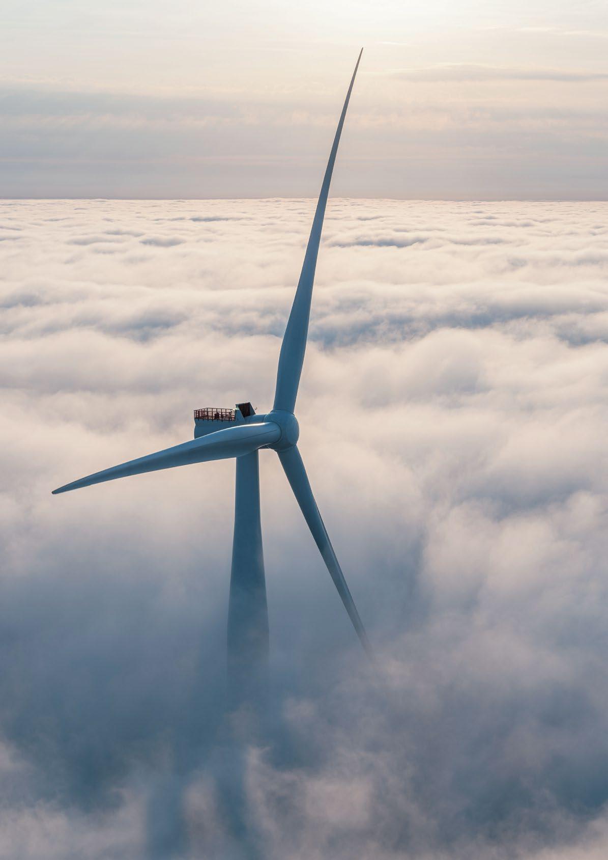
Norway marked the official dedication of the Hywind Tampen wind farm with a ceremony attended by Crown Prince Haakon of Norway and Norwegian Prime Minister Jonas Gahr Støre on the Gullfaks C platform in the North Sea. Billed as the world’s largest floating wind farm the project is unique in that it is being used to power mature offshore oil production while it is also seen as a further proof of concept project to support the development of floating wind turbines.
The wind farm was developed by Equinor with the company noting it took five years for the project to go from the drawing board to completion. The wind farm, which generated its first power in November 2022, consists of 11 wind turbines. Hywind Tampen has a system capacity of 88 MW and is expected to cover about 35 percent of the annual need for electricity on the five platforms Snorre A and B and Gullfaks A, B, and C.
The wind farm is located nearly 90 miles from shore. At a water depth ranging between approximately 850 and 980 feet, Hywind Tampen will be exposed to some of the harshest offshore conditions. The field lines to the northwest of the city of Bergen, Norway.

"Hywind Tampen is expected to reduce CO2 emissions with 200,000 tonnes annually from key oil and gas producers in the North Sea. It is a bold investment in a pioneering project from the Gullfaks and Snorre partnerships and Enova. The project has given us and the supplier industry valuable experience that will be important when we work together to develop offshore wind further in Norway and globally, scaling up for the future. I would like to thank everyone who has contributed, this is an industrial development we can be proud of," says Kjetil Hove, executive vice president for the Norwegian continental shelf in Equinor.
"40 years ago, Gullfaks was Equinor's major qualifying test in field development on the Norwegian continental shelf. Today marks a new milestone. With Hywind Tampen, we have shown that we can plan, build and commission a large, floating offshore wind farm in the North Sea. We will use the experience and learning from this project to become even better. We will build bigger, reduce costs and build a new industry
on the shoulders of the oil and gas industry," says Siri Kindem, head of Equinor's renewables business in Norway.
In five years, the project has gone from the drawing board to completion. 60 percent of the contract values in the project have been awarded to Norwegian suppliers. This has contributed to new activity, green jobs, local spin-offs and technology development for future floating offshore wind projects in a growing industry.
Enova and the Norwegian Business Sector's NoX fund have supported the project with NOK 2.3 billion and NOK 566 million respectively to stimulate technology development within offshore wind power and emission reductions.

The investment forecast for the project is now about NOK 7.4 billion. When the plan for development and operation was submitted, the development cost was estimated at about NOK 5 billion. The increase is due to a combination of COVID-related costs, delayed deliveries, quality issues with some deliveries and knock-on effects. In addition, increased market prices, currency effects and supplier compensation for COVID-19 effects have contributed. At the same time, the expected CO2 tax and gas price have increased, which has a positive effect on the project economy.
The project has significant cost improvements compared to the Hywind Scotland floating offshore wind farm, which was the world’s first floating offshore wind farm. Adjusted for price developments since 2016/2017, the investment cost for Hywind Tampen is about 35 percent lower per installed MW.


As from early August the campaign to install the first of 277 turbines at the world’s largest offshore wind farm is underway, marking a major advance in the industry and speeding up the transition to a cleaner, more secure energy system.

The scale of Dogger Bank Wind Farm is immense, occupying an area almost as large as Greater London, on seabed that once formed a land bridge between the UK and Europe. When fully complete it will have an installed capacity of 3.6GW of renewable electricity - more than two and a half times the size of the next largest offshore wind farm - and be capable of producing enough clean energy to power the equivalent of six million homes annually.
On a visit to Able Seaton Port in the North East of England to mark the occasion, Deputy Prime Minister Oliver Dowden said: "This project will generate cheap, clean energy to power millions of homes and provide the UK with greater energy independence in the face of Putin's energy ransom. Disruption to global energy supplies is one of the key risks we've highlighted in our new National Risk Register and working with SSE and its partners, we are making Britain more secure."
The commencement of the campaign to install GE Renewable Energy's 13MW Haliade-X turbines is a pivotal moment for the landmark project, which is being developed and built by the UK developer SSE Renewables in a joint venture wth a.o Equinor. It also represents a major milestone for the UK’s global leadership on offshore wind.
SSE CEO, Alistair Phillips-Davies said:
“Dogger Bank is one of the biggest and most complex engineering and infrastructure projects anywhere in the world. Our progress here with our joint venture partners Equinor and Vårgrønn proves that offshore wind projects of this size are now mainstream and will help turbocharge the transition to the cheaper, cleaner and more secure energy system we all want to see. It is action, not ambition, that will secure our energy future and this project shows action on a massive scale. But we will need many more Dogger Banks to achieve our goals and we look forward to working with government to bring forward more projects at pace.”
Equinor EVP Renewables, Pål Eitrheim said: “The imminent installation of the first turbine at Dogger Bank is a testament to the determination of the UK Government, the project partners, and the supply chain to deliver a worldclass offshore wind project for the UK. To reach our net zero goals, we will need even more of this collaboration. We’re delighted to soon begin operating Dogger Bank from our new O&M base at the Port of Tyne, which will host 400 jobs over the 35-year lifetime of the wind farm. We look forward to seeing the 277 turbines installed safely over the next three years, generating green electricity at scale and powering millions of British homes.”
Dogger Bank has created and supported more than 2,000 jobs, principally in the North East of England. Construction on this scale in the challenging conditions of the North Sea is unprecedented and the project has delivered a number of world-firsts that will significantly accelerate the speed at which future offshore projects can be developed. These include deployment of new 13MW and 14MW turbine technology, the world’s first unmanned offshore High Voltage Direct Current (HVDC) substation platform, and first use of HVDC technology on a UK wind farm

Mid August the DemoSATH project has achieved a significant milestone with the successful installation of its 2MW innovative floating wind platform demonstrator in open sea waters. The operation, carried out by the Windstaller Alliance, used their anchor handling vessel, the Normand Sapphire, along with local tugboats, to tow DemoSATH from the construction site in the Port of Bilbao to the BiMEP test site, located 11 miles away.
Once at the 85m deep BIMEP site, which is 2 miles offshore in the Cantabrian Sea, the hook-up operation involved connecting the six pre-laid mooring lines to the structure’s single-point mooring turret.

Works in the BiMEP area are ongoing to finalize the connection of dynamic and static cable and pull-in to the DemoSATH’s turret which will enable the energy export to the onshore electrical grid. DemoSATH is expected to generate the equivalent electricity needs of 2,000 Spanish households a year. The completion of this floating installation marks a major step forward in the project's mission to harness wind power and generate sustainable electricity.
David Carrascosa, Chief Operations Officer at Saitec Offshore Technologies highlights: “This milestone in the installation of the DemoSATH floating offshore wind project validates the years of steady commitment, resilience, and teamwork. Along the journey we have overcome some challenges that now serve as valuable lessons for future projects. We are proud of the achievements of our team, and the combined efforts of our collaborators. It's thrilling to witness the DemoSATH project set sail, playing an integral role in the progression of renewable energy.”
Sven Utermöhlen, CEO RWE Offshore Wind states: “The offshore installation of the DemoSATH project is an important milestone on our way to the commissioning of RWE’s second floating demonstration project. We see great potential for floating wind farms around the world as they unlock opportunities in countries with deeper coastal waters. As a floating pioneer the firsthand learnings from our demonstration projects are key to us optimizing our upcoming commercial scale projects and securing their safe delivery.”
Kazumi Ogura, Executive Officer, Renewable Energy Division, The Kansai Electric Power Co. declares: “We take great pride in our achievement of pioneering a new frontier in offshore wind power generation by installing the innovative floating wind platform demonstrator, thanks to major contribution from our partners. We will continue to prioritize safety and work together as a team to advance the pioneering DemoSATH project. Through DemoSATH project, we remain committed to continuous learning from the project and harnessing this knowledge to make progress towards achieving a zero-carbon society.”
During the 2-year operational period at the BiMEP site, the SATH technology for floating offshore wind developed by Saitec Offshore Technologies will be tested, and the tasks related to its operation and maintenance requirements will be analyzed. The project also aims to gain deeper insights into the metocean challenges in open sea, particularly in the harsh conditions of the Cantabrian Sea. Additionally, the collection of data will provide valuable knowledge regarding the coexistence of the platform with the environment and other maritime activities.

The DemoSATH project benefits from the combination of Saitec Offshore Technologies engineering design skills, RWE’s expertise in the offshore wind industry and the vast experience brought by Kansai Electric Power (KEPCO)
who joined the project earlier this year. In addition, the capabilities of multiple other companies involved and the institutional support from the Spanish Centre for the Development of Industrial Technology (CDTI) and the Basque Government institutions EVE and SPRI has ensured the success of the project.
With the installation of the unit now complete, the DemoSATH project will enter a period of commissioning, which will be followed by the operational phase when electricity generation will commence. The floating wind platform has been designed and equipped to harness the power of the wind in deep coastal waters and convert it into clean, renewable energy. This pioneering technology holds immense promise for reducing carbon emissions and contributing to the renewable energy goals of Spain and other countries around the world.
Publisher:
Uitgeverij Tridens
Strandweg 2
1976 BS IJmuiden
The Netherlands
Cover picture:
Ole Jørgen Bratland / Equinor
Digital version: www.oceanenergyresources.com
Editor-in-Chief: Han Heilig
E-mail: han@practica.nl
Contributing editors: Marloes Kraaijeveld (IRO)
Art Director: Peter Ruiter
Practica Productions BV
Advertising: Arthur Schavemaker E-mail: arthur-ocean-energyresources @kenter.nl
Jeanet Draaijer E-mail: jeanet-ocean-energyresources @kenter.nl
Phone: +31 547 27 50 05
Copyright Ocean Energy Resources is owned and published by Uitgeverij Tridens.
The publisher, authors and contributors reserve their rights in regard to copyright of their work.
No part of this work covered by the copyright may be reproduced, stored or transmitted in any form or by any means without the written consent of the publisher.
While every care has been taken in the preparation of this publication, neither the publisher nor the editor are responsible for the views and opinions expressed in this publication or for any inaccuracies in the articles.
ISSN: 2598-7853

Hungary will start receiving shipments of liquified natural gas from Qatar beginning in 2027 in an agreement between the two countries announced mid-August.
Hungarian Foreign Minister Peter Szijjarto said that Qatar, the world's biggest LNG exporter, currently has no more LNG available for export and the details of the agreement are yet to be determined, according to Reuters.
Szijjarto said at a news conference: "We have reached a political agreement, which is now followed by talks between energy companies Qatargas and Hungary's MVM to determine the quantity, pace and shipment route of the supplied gas to Hungary from 2027."
Hungary’s demand for LNG has surged along with the rest of Europe, propelled by sanctions imposed by the European Union on Russia after it declared war on Ukraine in February 2022.
Natural gas makes up about a quarter of the EU’s overall energy consumption, with more than 15% of its gas needs imported through natural gas piped or shipped, according to the European Commission. Before the conflict with Ukraine, Russia supplied around 40% of all pipeline imports.
As the EU reduced its reliance on Russian gas, it increased its US imports. The United States became the EU’s top LNG supplier at 41% of its imports in all of 2022, according to data collected by commodity market solutions company Kpler.
Europe is also looking at Qatar, which reclaimed its position as the largest LNG exporter in 2022 with 80 million tons of LNG, according to the Gas Exporting Countries Forum report. According to ship-tracking data collected by Bloomberg, the Gulf state tied with the United States as the world’s top LNG exporter last year with 81.2 million tons.
Last November, Qatar signed a 15-year deal to supply Germany - Europe’s largest gas marketwith two million tons of LNG annually, reported Reuters. Deliveries will start in 2026.

Heavy maintenance on two of the floating wind turbines at Kincardine
In late May, the second floating wind turbine from Pilot Offshore’s five-turbine Kincardine development off the east coast of Scotland arrived in port for maintenance. The KIN-02 turbine was delivered by JD Contractor’s AHTS Assister to the quayside at the port of Maasvlakte, Rotterdam. This was two weeks after PSV Coco and AHTS BB Ocean had disconnected the turbine from the wind farm site. I
The first floating wind turbine from the Kincardine wind farm, KIN-03, had also been disconnected and towed for repair in the summer of 2022. This marked the first incidence of a floating wind turbine requiring heavy maintenance (i.e. being disconnected and towed for repair) anywhere in the world. KIN-03 was also towed from Scotland to Maasvlakte.

With maintenance of the second turbine ongoing, we can take the opportunity to examine what lessons can be learned from the world’s first example of heavy maintenance of a floating wind turbine.
Kincardine is the first commercial-scale floating wind farm in the UK sector and, as such, has been watched closely by the industry through each stage of its development. When one of the five floating Vestas V164-9.5 MW turbines, KIN-03, suffered technical failure last May, a major technical component needed to be replaced. The heavy maintenance strategy selected
by the developer, Principle Power, and the offshore contractors (JDContractor and Buksér og Berging), consisted in disconnecting and towing the turbine and its floater to Rotterdam for maintenance, followed by a return tow and re-connection. All of the infrastructure, such as crane and tower access, remained at the quay following the construction phase.
A comparison of net vessel days for the maintenance and installation campaigns at this operation highlights the potential upsides of using a dedicated marine spread to allow for easy maintenance operations. Turbine reconnection during maintenance stands at 17.2 net vessel days, similar to the first hook-up operation performed during installation in 2021 (14.6 net vessel days). However, this exceeds the installation average of eight net vessel days per turbine. The new marine spread used during the heavy maintenance operation differed from the one used during installation, therefore it did not benefit from the learning curve and experience from the initial installation campaign.

A similar effect was encountered during the array cable re-connection part of the maintenance programme. It was performed by one AHTS which spent a total of 10 net vessel days on the operation. This compares to the installation campaign where the array cable second-end pull-in lasted a maximum of 23.7 hours using the cable layer Maersk Connector.
The full breakdown of the turbine shutdown duration was 14 days at the quay for maintenance, 52 days from turbine disconnection to turbine reconnection and 94 days from disconnection to the end of post-reconnection activities.

Two main lessons emerged from the first heavy maintenance operation at Kincardine: the need to identify an appropriate O&M port and to ensure a secure fleet is available.
A port requires sufficient room and a deep water quay in order to be suitable for O&M in floating offshore wind. It needs to be equipped with a heavy crane with sufficient tip height to accommodate large floaters and reach turbine elevation. Furthermore, the distance to the wind farm is a key element in reducing towing time to minimize transit and non-productive turbine time.
During the heavy maintenance period for KIN-03, the selected quay (which had also been utilized in the initial installation phase of the wind farm project) was already busy as a marshalling area for other projects (HKZ and
Dogger Bank A). This complicated the schedule significantly as the availability of the quay and its facilities had to be navigated alongside these other projects. This highlights the importance of abundant quay availability both for installation (long-term planning) and also for maintenance sometimes at short, unexpected notice.
At the time of KIN-03’s maintenance (June 2022) the North Sea AHTS market was in an exceptional situation with the largest bollard pull AHTS units contracted at over $200k a day: the highest rate in over a decade. The spot market was nearly sold-out due to medium-term commitments alongside the demand for high bollard pull vessels for the installation phase at the Norwegian Hywind Tampen floating wind farm project. Hywind Tampen’s installation required the use of four (out of 41 trading in the North Sea market) AHTS above a 200t bollard pull.
Two crane concepts are especially relevant in this instance. The first method is for a crane to be included in the turbine nacelle to be able to directly lift the component which requires repair from the floater. This is what can currently be seen on onshore turbines.
The second method is self-elevating cranes. Several such solutions are already in development including Mammoet’s SK6,000 crane; WindSpider, which is supported by RWE; and Liftra ApS which is supported by DEME. The Mammoet solution, which is capable of lifting over 4,000t to a height of 175m with a maximum reach of 144m, allows developers more flexibility when utilizing onshore facilities as part of the installation and O&M programmes. Meanwhile, WindSpider is self-erecting and uses the tower of a wind turbine as part of the crane when performing installation, maintenance, re-powering, and decommissioning of wind turbines. Finally, Liftra is also self-erecting.
To sum up, the heavy maintenance of floating turbines at the Kincardine wind farm has provided valuable lessons for the industry. The requirement to disconnect and tow turbines for repair proved to be a complex and time-consuming process, highlighting the need for careful planning and consideration of alternative maintenance strategies, some of which are already in development.
The key takeaway from this is that developers will need to structure maintenance contracts with AHTS companies either through frame agreements or long-term charters to decrease their exposure to spot market day rates.
While these lessons are key for floating wind developers in the immediate future, new players are looking towards alternative heavy O&M maintenance.

Analysis of the installation compared to the maintenance campaign revealed that the lack of a consistent marine spread for maintenance resulted in significantly more vessel days. As such, two important lessons have been learned: the identification of an appropriate O&M port with sufficient facilities and availability, and the establishment of secure fleet contracts to mitigate exposure to high spot market day rates.
This full insight has been written by Sarah Mclean, Content Writer/ Market Research Analyst at Spinergie. This company transforms operational and maritime data into actionable insights to reduce your carbon footprint and increase efficiency.
With spot dayrates ranging from $63k to $210k contracted for Kincardine’s maintenance, the total cost of the marine spread used in the first repair campaign was more than $4 million.
Two main lessons emerged from the first heavy maintenance operation at Kincardine: the need to identify an appropriate O&M port and to ensure a secure fleet is available.

The term significant wave height (Hs) represents the average height of the 1/3 highest measured waves within a period of 20 minutes; it can also be provided for a 3 hour range. The highest sea state depends on the actual metocean area. Within a sea state described by a significant wave height, the actual maximum wave height could be a multiple of 2, 3 and more than 4 of the representative Hs. The maximum can be defined in several ways, for instance:
‘most probable largest wave in x number of waves’, ‘expected largest response’ or ‘extreme response with 1% probability of exceedance’.
It must be emphasized that equally important as the wave height is the wave period. In terms of motion, the response of the vessel can be amplified several times. This means that the vessel response in a sea state with a low wave height and critical wave period can be higher compared to a sea state with a higher wave height but ‘better’ wave period. In addition, a Hs – Tp combination (usually applied to describe a sea state) can occur in many ways and by many types of wave spectra. So the vessel response in a given Hs – Tp will vary dependent on the wave spectra that is utilized. Wave spectra is defined in statistical terms and can have a large influence on capability calculations.
A gangway designer can use this information to decide required speed, amplitude and acceleration of the gangway in active motion compensation and estimate the dynamic loads.

Various hull designs will respond differently to waves, but in general a larger hull has less heave and pitch motion. Roll motion is mainly influenced by the vessel’s natural period. Seakeeping simulation software is used by the ship designers to calculate the response of a given hull for various Hs and wave periods, headings and loading conditions. Most seakeeping software calculate a physical quantity called the ‘response amplitude operator’, RAO. This describes the vessel’s motion characteristics in all degrees of freedom (surge, sway, heave, roll, pitch and yaw). The RAO assumes a relation between the wave spectra and vessel response, meaning that if the RAO and wave spectrum is known, the vessel response in a given sea state can be described for any fixed point on the vessel.
When RAOs are known, the motion amplitude, velocities and accelerations can be calculated for the end of a gangway over the ship side at a given height above deck. From this data it is possible to determine maximum velocity and acceleration based on wave period and ship heading. This is provided that the definition of the maximum is precisely defined.
A gangway designer can use this information to decide required speed, amplitude and acceleration of the gangway in active motion compensation and estimate the dynamic loads. The basic gangway is designed as general purpose equipment, not specially designed for a particular vessel. It is impossible to give a blanket statement of ‘this gangway will work in 3,5 mHs’ on any vessel. The actual capability is dependent on the maximum speed, amplitude and acceleration of the gangway and the responses and motions of the hull.

Ulmatec uses the ShipX and Veres software from the Sintef research company, a partner of NTNU, Norwegian University of Science and Technology. Sintef is one of the leading research for ship design and simulation.


With a set of RAOs for a hull and a defined wave spectrum, we can simulate the motions of the hull and the compensation required of the gangway tip. This capability plot will show the maximum Hs at different headings and gangway orientation, typically 90 degrees off to one side. With the rotating tower, the Ulmatec gangway can be turned to other headings which may increase workability. Simulations have shown a 30% increase for certain headings.


The control system will warn when any one of the operational limits for the system is exceeded.

An important factor is the distance from the gangway end to the ship centerline in the X-Y plane and distance from the gangway end to the axis of the motions eg. the axis the hull is pitching around.

Another factor is the distance from the origin of motion to the end of the gangway in the Z axis, the height. The greater the distance the more work the gangway has to do in order to stay stationary in 3d space, in contact with a wind turbine, for example.

The use of a gangway also exerts force on the structural components. Material fatigue is an important issue and needs to be simulated and calculated for the expected liftetime of the gangway. A typical use is estimated, hours per day in cantilever mode in a windfarm (for example), and the average and peak loads during the lifetime and the number of crane lifts or number of people crossing on the gangway in AMC mode.
For a flotel gangway the number of emergency liftoffs and the load on the gangway during a liftoff is used. The FEM analysis is part of the DNV, ABS or other class approval of the gangway.

The loading condition (metacentre height, centre of gravity, actual weight distribution) for a SOV usually does not change much in operation and the motion characteristics are usually related to one loading condition.
Be aware of the fact that all simulations of ship motions are based on assumptions and will not be 100% accurate. In real life other motions may occur and safety factors should always be applied, depending on the consequence if the values are exceeded.
Original text: Bjørnar Huse, Ulmatec Handing Systems.
The basic gangway is designed as general purpose equipment, not specially designed for a particular vessel.Typical illustration of a stressed joint.

Manon van Beek, CEO TenneT: “The Netherlands wants to be climate neutral by 2050 and offer green economic growth to Dutch citizens. An important goal and at the same time a huge task for everyone. The operation we are working on is comparable to the Delta Works that shortened the coastline by some 700 kilometres in 43 years. And perhaps even more ambitious than that. We are going to expand our high-voltage grid on land and at sea by hundreds of kilometres while we have only 22 years to do so. This transformation of our energy system must continue at maximum speed to meet climate targets, to ensure a secure energy supply and, not least, to keep the system affordable. A new cabinet will have the opportunity to make important choices and take decisions. Our seven key points will help it do so.”
The seven key points are:
Stick to the principles of the National Energy System Programme (NPE) and use Target Grid for the development of the high-voltage grid on land and at sea. This will enable us to have the necessary infrastructure ready in time for a carbon-free energy system.
Creating space for the growth of our electricity grid is essential for the energy transition. Therefore, literally reserve space based on relevant government programmes such as the Spatial Planning Policy Document, Energy Main Infrastructure Programme and VAWOZ.
Quickly implement the European Directive REDIII and give electricity infrastructure priority when distributing nitrogen space from the nitrogen bank. Without the ability to expand and develop the electricity grid, the desired energy transition is unfeasible and also restricts the growth of housing and making the economy more sustainable.
Give grid operators the mandate to work together with EZK, the Provinces and Energy Storage NL to have installed batteries at the right locations and set up a governmental pool with energy advisers to help entrepreneurs with flexible energy consumption. Also maintain the Landelijke Aanpak Netcongestie.

TenneT has identified seven important key points of great value for a truly sustainable future for the Netherlands. Seven key points that are essential to perform our tasks well and that help realise the transition to a CO2-free energy system in the Netherlands. The key points can be important for a new cabinet and energy policy in the coming years.
'The operation we are working on is comparable to the Delta Works that shortened the coastline by some 700 kilometres in 43 years. '
Manon van Beek, CEO TenneT.
Achieving sustainability targets is not the only issue. Security of supply is also essential to maintain political and social acceptance and thus progress in the energy transition. TenneT’s Monitoring Leveringszekerheid and Adequacy Outlook offer analyses, facts, and applicable recommendations. A crucial recommendation from our latest monitor reports is to develop concrete policies to ensure the availability of sufficient CO2-free, controllable power generation capacity.

A well-functioning electricity system based on renewable energy needs good connectivity via interconnectors with other countries for security of supply. Given the scarce space, the direction of integral planning and the safeguarding of social benefits for citizens, hybrid interconnectors connected to our offshore grid are the best option. It is important that TenneT is given a clear legal task to realise these.
It is essential to align the sustainability of industry with the growth of CO2free electricity production. Especially from offshore wind and nuclear energy.
This requires a programmatic approach to:
g define the most appropriate locations for industry: the closer to the energy source,the better
g align the realisation of sustainable electricity production with the sustainability process of the industry: the better timed, the better
g coincide the electricity consumption profile of industry with the production of CO2-free electricity as much as possible.


Havkraft, a pioneering Norwegian corporation in renewable energy technology, and Neuto, a leading Singapore-based renewable technology company, have joined forces to spearhead a green transition in Southeast Asia through the harnessing of ocean energies, particularly the Havkraft N-class wave power plant.
The strategic partnership was formalized with the signing of a Memorandum of Understanding (MOU) in August 2023, marking the commencement of a transformative collaboration.
Havkraft's proprietary Havkraft Wave Energy Converter (H-WEC) technology, which includes revolutionary wave power products like the Havkraft N-class, holds immense promise for the renewable energy sector in Southeast Asia. By capitalizing on Neuto's extensive expertise and regional presence, the Parties aim to accelerate the adoption and integration of this advanced technology within local markets, fostering a greener and more sustainable future.
Geir Arne Solheim, the inventor, founder and CEO of Havkraft AS, expressed his enthusiasm for the strategic partnership, stating: "At Havkraft, we firmly believe in the potential of ocean energies,
particularly wave power, to drive sustainable development and address pressing environmental challenges. Partnering with Neuto, a prominent player in the Southeast Asian market, is a significant milestone that will enable us to take our innovative Technology to new horizons, making a profound impact on the region's renewable energy landscape."
Andy Low, the founder and CEO of Neuto, highlighted the importance of this collaboration for the green transition in Southeast Asia, saying: "Southeast Asia presents vast opportunities for renewable energy growth, and wave power holds tremendous potential as a clean and reliable source. By aligning our strengths with Havkraft, we are poised to deliver innovative solutions to our region, accelerate sustainable development, and play a vital role in realizing a green future for Southeast Asia."

In deeper, more open waters up to 5,000 feet deep over continental shelves, drilling is done from free-floating platforms or from platforms made to rest on the bottom. Floating rigs are most often used for exploratory drilling and drilling in waters deeper than 3,000 feet, while bottom-resting platforms are usually associated with the drilling of wells in an established field or in waters shallower than 3,000 feet.
One type of floating rig is the drill ship, which is used almost exclusively for exploration drilling before commitments to offshore drilling and production are made. This is an oceangoing vessel with a derrick mounted in the middle, over an opening for the drilling operation. Such ships were originally held in position by six or more anchors, although some vessels were capable of precise manoeuvring with directional thrust propellers. Even so, these drillship roll and pitch from wave action, making the drilling difficult. Additional production is established by a direct connection with the production platform or by connecting risers between the subsea wellheads and the production platform.
The Seastar floating system operates in waters up to 3,500 feet deep. It is essentially a small-scale tension-leg platform system that allows for side-to-side movement but minimizes up-and-down movement. Given the vertical tension, production is tied back to ‘dry’ wellhead (on the surface) or to ‘trees’ on the platform that are similar to those of the fixed systems. Drilling platforms capable of ultra-deepwater production line that is, beyond 1,830–2,130 meters deep, include tensionleg systems and floating production systems (fps), which can move up and down in response to ocean conditions as semisubmersibles perform.
Without such infrastructure, wet trees are used and petroleum is exported to a nearby FPS. A more versatile ultra deepwater system is the spar type, which can perform in waters nearly 3,700 meters (approximately 12,000 feet) deep. Spar systems are moored to the seabed and designed in three configurations: (1) a conventional one-piece cylindrical hull, (2) a truss spar configuration, where the midsection is composed of truss elements connecting an upper, buoyant hull with a bottom element (soft tank) containing permanent ballast, and (3) a cell spar, which is built from multiple vertical cylinders. In the cell spar configuration, none of the cylinders reach the seabed, but all are tethered to the seabed by mooring lines.
Author: Mohsen Fatahi, Directional Drilling Project Manager.The option to produce from wet (submerged) or dry trees is considered with respect to existing infrastructure, such as regional subsea pipelines.
There are clear obstacles and hurdles to a smooth This This paper presents the performance of a new, floating, mono-hull wind turbine installation vessel (Nordic Wind) in the installation process. The vessel can transport pre-assembled wind turbines from the marshalling port to the offshore installation site. Each assembled turbine will be positioned over the pre-installed floating spar structure. The primary difficulty lies in examining the multibody system’s reactions when subjected to combined wind, current, and wave forces. Time-domain simulations are utilized to model the interconnected system, incorporating mechanical coupling between components, the mooring system for the spar, and the installation vessel. The primary objective is to focus on the monitoring and connection stages preceding the mating operations between the turbine and the floating spar. Additionally, it involves examining the impacts of wind, current, and wave conditions on the motion responses of the installation vessel and the spar, as well as the relative motions at the mating point, gripper forces, and mooring forces. The simulations show that the resulting gripper forces are reasonable to compensate. The relative motion at the mating point is not significantly affected by the orientations of the turbine blades, but it is influenced by the prevailing wave conditions. In addition, vessel heading optimization can minimize the relative motions at the mating point and gripper forces. Given the examined environmental conditions, the presented installation concept exhibits a commendable performance.
Author: Mohamed Hassan, Principal Engineer Marine Operations at Equinor.


Renewable energy from wind power is expanding globally, establishing itself as a prominent and increasingly significant source of sustainable energy, as the economic conditions are favourable. To address the need for alternative energy sources, a considerable number of wind power generators are being deployed in wind farms, both on land and offshore. European offshore wind capacity grew by adding 3.4 GW of offshore capacity during 2021, reaching a total installed capacity of 17.4 GW. Due to the varying quality of wind resources and geographical constraints, numerous countries are now contemplating the utilization of deep-water offshore areas for future wind power facility development. As of the end of 2020, Europe’s floating wind fleet reached a cumulative capacity of 62 MW, representing 83% of the global floating wind capacity. Floating offshore wind (FOW) is seen as a crucial factor in unlocking Europe’s vast and virtually limitless wind energy potential. Around 80% of the offshore wind resources in European seas are located in waters with depths of 60 m or greater, where traditional bottom-fixed offshore wind (BFOW) installations are not economically viable or attractive.
The world’s first floating wind turbine farm, utilizing Equinor’s Hywind technology from Norway, was commissioned in Scotland in late 2017. The floating wind turbine farm comprises five 6 MW turbines, provided by Siemens. Prior to installation, the turbine blades, nacelle, and tower are pre-assembled onshore. The installation process involves using the SAIPEM 7000, one of the largest semi-submersible crane vessels, to lift and place the components onto the spar floaters in the deep fjord of Norway. Subsequently, the pre-assembled turbines on the spar floaters are then transported via wet towing to offshore Scotland. Once in position, they are connected with mooring systems to secure their stability. The Hywind Tampen project, with a capacity of 88 MW, attained the Financial Investment Decision in 2019 and is currently in the pre-construction phase. The objective of the project is to achieve a cost reduction of 40% compared to Hywind Scotland, which served as the initial demonstration of the spar-buoy technology [10]. Nevertheless, the current installation method still involves assembling the turbines in a sheltered location and then towing each complete assembly individually to the installation site for final commissioning.

To continue cost reduction and development of floating offshore wind projects, the following key areas shall be considered:
• Industrialization: optimize design of substructure and mooring and reduce the cost per ton towards mass production levels.
• Economics of scale: larger parks will drive down costs for infrastructure and logistics.
• Upscaling: follow the bottom-fixed industry towards turbine sizes of 10 - 15 MW.
Figure 1 illustrates the three primary designs for floating offshore wind: tension leg platform, semi-submersible, and spar buoy. The semi-submersible and spar buoy structures, unlike the tension leg platform, are loosely moored to the seabed. This loose mooring configuration facilitates simpler installation processes. In contrast, the tension leg platform is firmly connected to the seabed.
• Technology development: establish new and more efficient methods for installation, operation, and maintenance. Offshore wind developers have recognized the preference for new installation methods that rely on cost-effective large crane vessels when developing commercial wind farms. This shift is driven by the aim to reduce expenses associated with installation operations. This will enhance the development of mass production towards potential future long-term markets. In the context of the Hywind installation challenge, there is a preference for innovative installation concepts that prioritize the use of novel installation vessels and facilities. The goal is to minimize offshore lifts and reduce the overall operation time involved in the installation process. The assembly and installation cost for offshore wind turbines (OWT) is relatively high and can account for approximately 20% of the total capital expenditures incurred in the development of offshore wind farms [11–14]. It is, therefore, crucial

Thispaper presents the performance of a new, floating, mono-hull wind turbine installation vessel (Nordic Wind) in the installation process.
to employ cost-effective installation methods in order to mitigate the high assembly and installation costs associated with offshore wind turbines. Implementing efficient and economical installation techniques is vital for the overall financial viability and success of offshore wind farm projects.
Two common types of vessels used for offshore wind turbine installation are jack-up vessels and floating crane vessels. Jack-up vessels offer a stable working platform for the installation of foundations, allowing for safe and efficient operations. These vessels are equipped with extendable legs that can be lowered to the seabed, providing stability during installation activities. However, the process of installing and retrieving the jack-up legs is time-consuming and highly dependent on weather conditions. Additionally, the stability of the jack-up unit relies heavily on the specific characteristics of the seabed, which can introduce uncertainties. Furthermore, jack-up vessels have limitations regarding the water depth in which they can operate effectively. In contrast to jack-up vessels, floating crane vessels offer greater flexibility for offshore installations and are particularly effective in the mass installation of wind farms. These vessels can swiftly move between foundations, facilitating efficient and rapid deployment. Their enhanced mobility makes them well-suited for large-scale wind farm projects. However, during the installation process, the motions of the floating installation vessel and the lifted objects are intricately coupled and are highly responsive to environmental conditions. This interdependence introduces challenges, as the movement of one affects the stability and control of the other. Therefore, careful consideration of environmental factors is crucial to ensure safe and successful installations. It is important to note that the installation cost associated with floating crane vessels is typically higher compared to jack-up crane vessels. Therefore, when making the selection of a crane vessel for practical operations, a well-balanced consideration between technical feasibility and cost is necessary. Finding the right balance ensures that the chosen vessel meets the technical requirements, while keeping the overall project cost within a feasible range.
Currently, there are ongoing efforts to utilize floating crane vessels for various offshore wind turbine installation tasks. These include the installation of monopile foundations for bottom-fixed wind turbines, the assembly of the tower-rotor-nacelle components for floating wind turbines, as well as the installation of tower-nacelle assemblies and rotors for floating wind turbines. These attempts demonstrate the exploration of alternative installation methods to meet the specific requirements of different types of wind turbine structures. The installation of blades for offshore wind turbines presents greater challenges compared to other components, such as foundations and transition pieces. This is primarily due to the need for precise installation during the final blade mating phase, which demands a high degree of accuracy. Additionally, at significant lifting heights, there is relatively large motion between the turbine hub and the blade
root, further complicating the installation process. The combination of high installation precision and substantial motion necessitates careful planning and specialized techniques to ensure successful blade installation. Enhancing the weather window and mitigating unforeseen delays emerge as crucial challenges in reducing the cost of offshore installations. To accomplish this, it is essential to conduct precise evaluations of the installation vessels and methods to gauge their performance accurately. Furthermore, there is a need to develop numerical methods and models that can estimate the dynamic responses of systems during the installation process. These efforts aim to enhance the understanding and prediction of system behaviour, allowing for informed decision-making and optimization of offshore installation operations.
Due to its substantial capacity and cost-effectiveness, the float-over method has gained significant popularity in the oil and gas industry for installing large decks onto offshore platforms. The float-over method offers several notable advantages for installing integrated topsides onto a floating substructure, especially when dealing with large topsides that surpass the lifting capacity of existing heavy-lift fleets. These advantages encompass time and cost savings by allowing the integration and commissioning of modules to take place on land, instead of at sea. Additionally, decoupling the fabrication schedules of the topside from the availability of heavy-lift vessels is another significant benefit.
The innovative installation concept, named by the current author as Nordic Wind, draws inspiration from the float-over method. The primary objective of this concept is to eliminate weather-dependent high lifts conducted from a floating vessel and reduce offshore installation time. This concept has the versatility to be employed for both fixed and floating offshore wind turbine installations.
The design of the installation vessel allows for the transportation of at least three pre-assembled wind turbines. The actual number of turbines that can be transported will vary, based on their individual capacity and weight. When compared to the previously mentioned methods, this innovative concept will significantly reduce the need for offshore lifts and installations. As a result, it will lead to a decreased operational time and cost. To ensure a safe installation operation, the vessel is equipped with precisely designed complex mechanisms. The concept includes a motion compensation gripper positioned at the stern of the vessel, along with two lifting grippers and a skidding truss structure system. The connection between the vessel and the floating spar will be established using the motion compensation gripper. The primary purpose of the motion compensation gripper is to minimize the horizontal plane motions that occur between the vessel and the floating spar. The truss structure system is designed with the capability to move in both forward and backward directions. This allows for the selection and lifting of the turbine assembly using both the upper and lower lifting grippers. The design of the lifting grippers should enable them to securely hold turbine assemblies weighing a minimum of 1200 tons.
Additionally, the lifting grippers will be designed with heave compensation capabilities to reduce the impact forces experienced during the mating operation. To secure the floating spar to the seabed, three mooring chain lines will be utilized. On the other hand, the installation vessel will rely on its own thrusters and employ a dynamic positioning system (DP). Figures 2 and 3 illustrate the key components of the installation concept. The stability of the vessel has been assessed under different loading conditions, considering both the transit and installation phases.

The installation method consists of several key steps, which are as follows:
• Fully assembling the turbine onshore using a crane before the arrival of the installation vessel.

• Loading the turbine assembly onto the installation vessel.
• Transporting the turbine assembly to the installation site.
• Approaching the floating spar with the installation vessel and connecting it to the spar using the motion compensation gripper.
• Transferring the turbine assembly from the installation vessel to the floating spar.

• Mating the turbine assembly in place.
In Figure 4, the installation steps were illustrated starting from assembly, loadout, transportation, and, finally, the mating operation. The installation process will be started once the installation vessel connects the motion compensation gripper to the floating spar. The marine and operational crew will monitor the weather and the forecasted motion and response in order to allow for safe lifting and mating operations. The weather and vessel motions can be monitored by any decision support tool onboard, such as the Octopus system or any other system of the same type. This kind of system can accurately and clearly show how the incoming weather will impact the operation execution. The forecasted motions will be presented in a simple way to aid the crew of the vessel to make decisions based on the available data.
Figure 2. Nordic Wind concept’s main components overview (artistic impression). Figure 3. Illustration of installation concept’s main components (not to scale).Once the vertical relative motion is within the limits, the mating operation between the turbine and the spar can start. The mating process will be considered complete when the guiding pins located at the bottom of the tower successfully enter the docking device situated inside the floating spar. Once the mating operation is completed, the spar draft will be increased by 5 m - 10 m, depending on the tower weight.
This paper primarily focuses on the monitoring and positioning phases that precede the mating operations. The lifting grippers are not included in the modelling process, since they do not impact the relative motions in the horizontal plane or the forces exerted by the grippers. The design of the lifting grippers should prioritize the minimization of impact forces. These modelling features will be subject to future investigations. Furthermore, an analysis of the operational limits will be taken into consideration.

The primary objective of this study is to examine the hydrodynamic performance of the new installation concept during wind turbine installation. To achieve this, accurate and realistic modelling is essential in order to accurately quantify the dynamic responses during various installation phases and critical stages. This detailed analysis will facilitate improved operational planning. There are several key challenges to model the entire installation process.
To overcome the above challenges, the dynamic model has been divided into several key stages in the next, and are explained as follows:

Dynamic system stages for the installation phase.
Loading condition 1: which corresponds to the monitoring stage, where structure responses are monitored prior to gripper connection.
Loading condition 2: which corresponds to the connection stage between the floating spar and the installation vessel.
Loading condition 3: which corresponds to the installation phase for lowering the turbine to the floating spar (mating operation).

The primary objective of this study is to examine the hydrodynamic performance of the new installation concept during wind turbine installation.
The coupled dynamic system of the installation vessel and the floating spar was simulated and modelled using ANSYS AQWA software for numerical analysis. ANSYS AQWA offers a comprehensive set of tools specifically designed to analyze and assess the impact of environmental loads on various types of offshore and marine structures, including both floating and fixed structures.

The global coordinate system (GCS) employed in this context is a right-handed coordinate system. Its orientation is defined as follows: the X-axis points towards the bow, the Y-axis towards the port side, and the Z-axis points upwards. The origin of the GCS is situated at the mid-ship, center line, and still waterline position when the vessel is at rest. Each floating body exhibits six degrees of freedom. Assuming a linear and harmonic response, the coupled differential equations of motion for the floating bodies can be expressed in the following format:

In the present study, the added mass and potential damping were computed in the frequency domain and subsequently utilized in time domain simulations. These calculations were performed to analyze the coupled motion of two bodies through the implementation of retardation functions. The analysis also considers the viscous damping effects on both the vessel and spar. Figure 7 illustrates the hydrodynamic panel model employed for the installation vessel and the floating spar. The calculations incorporate first- and second-order hydrodynamics, based on the potential theory. Figure 8 depicts the Response Amplitude Operators (RAOs) for heave and pitch motions of both the installation vessel and the spar. These RAOs were evaluated under specific sea conditions, known as following sea conditions.

The utilization of the generalized mode concept proves to be effective in addressing multi-body hydrodynamic interaction problems. By employing this concept, a multi-body system consisting of NB body units can be represented by 6 multiplied by the number of bodies (6XNB) degrees of freedom, assuming that each body behaves as a rigid body. In the case of multi-bodies that are hydrodynamically and mechanically coupled, the equation mentioned above needs to be solved in a coupled matrix equation. In the model, the installation vessel and the spar foundation are represented as two rigid bodies that are interconnected through mechanical and hydrodynamic couplings at their interfaces. Both bodies experience wave-induced forces, hydrodynamic reaction forces, and mechanical coupling effects.
The equation of multi-body motion is given below:

In this initial study, all wind turbine assemblies present on the installation vessel are connected rigidly. Mooring systems were separately incorporated for both the spar and the installation vessel.
 Figure 7. Hydrodynamic panel model for the vessel and the floating spar
Figure 8. (a) Heave RAO for the installation vessel;
(b) Pitch RAO for the installation vessel;
Figure 7. Hydrodynamic panel model for the vessel and the floating spar
Figure 8. (a) Heave RAO for the installation vessel;
(b) Pitch RAO for the installation vessel;
Within ANSYS AQWA, wind loads can be simulated using various spectrum options or by specifying a constant velocity. This allows for flexible modelling of wind-induced loads in the analysis. The wind field in the analysis is assumed to propagate parallel to the horizontal plane. The fluctuating component of the wind velocity in the mean direction is described using the NPD spectrum, as defined in API RP2A. This spectrum provides a characterization of the varying wind velocity for the simulation. The average wind speed profile at a specific elevation z, denoted as Uz, can be approximated by the following equation:
In this study, the current was modelled using the power law method, where the current direction remains fixed and does not vary with depth. The current speed, denoted as S, varies with position (X, Y, Z), according to the following formula:


In the present study, the wind forces generated by the wind turbines installed on the vessel deck were considered. The wind coefficients required for the calculations were determined using HAWC2 software. The wind coefficients for the installation vessel were obtained through model tests. Figure 9 illustrates the changes in force and moment coefficients, with respect to wind direction for the wind turbine.
Specifically, two blade orientations were taken into consideration: blade pitch angles of 0 degrees and 90 degrees.
Understanding the effects of modelling mechanical couplings on the dynamic characteristics of a system is important. In this study, the mechanical coupling between the ship and the floating spar substructure was achieved using a motion compensation gripper.


In the dynamic model, the motion compensation gripper is simplified using a mechanical joint. This mechanical joint enables independent rotation of both bodies, allowing them to move freely, with respect to each other. However, it should be noted that, despite the independent rotation allowed by the mechanical joint, the two bodies will remain rigidly connected in the longitudinal and transverse directions. The primary objective of the motion compensation gripper frame is to facilitate the installation process by compensating for the relative motions in the horizontal plane between the floating spar and the installation vessel. By mitigating these relative motions, the motion compensation gripper frame helps to ensure smoother and more efficient installation operations. Figure 10 shows the mechanical joint between the installation vessel and the floating spar, as modelled in ANSYS AQWA.
Figure 9.
(a) Wind force coefficients for blade pitch 90 deg;


(b) Wind moment coefficients for blade pitch 90 deg;

(c) Wind force coefficients for blade pitch 0 deg;
(d) Wind moment coefficients for blade pitch 0 deg.
Figure 10. Mechanical connection model (ANSYS AQWALeft).The mooring system for the spar is composed of three separate lines that are connected to the substructure through bridles. The pretension and configuration of the bridles provide sufficient yaw stiffness, which helps prevent slack in the mooring lines during normal operation. This ensures the stability and proper functioning of the spar structure.
behaviour before introducing the mechanical gripper connection. Moreover, it was feasible to assess how the hydrodynamic interaction between the two bodies affected the resultant movements of the motion reference point (MRP).

The primary goal of the study is to assess the performance of the installation concept under varying wind, wave, and current conditions. To achieve this, multiple time domain simulations were conducted, considering different environmental conditions specific to the Hywind Tampen location.

For time-domain simulations, some reference points are considered to give insight into vessel and spar motions. The following points are considered and shown in Figure 12:
The computation of linearized hydrodynamic wave-loading on floating bodies is performed using AQWA-LINE, which utilizes three-dimensional radiation/diffraction theory. The concept of fluid interactive loading between bodies is commonly discussed in the context of radiation/ diffraction theory. Radiation forces, in essence, pertain to the impact of one body’s flow field on another. The significance of such interaction depends on factors such as the separation distance between the bodies and the relative sizes of the bodies involved. During the connecting phase between the installation vessel and the floating spar, the importance of this interaction becomes apparent as the two bodies come into close proximity. In addition to the radiation coupling, the hydrodynamic interaction also includes the shielding effect, which refers to the change in the flow field around a body due to the presence of another nearby body. This effect can have a significant impact on the wave loads and motions of the interacting bodies.
A series of time domain simulations were initially conducted without incorporating the mechanical gripper connection between the installation vessel and the spar. These simulations aimed to assess the dynamic behaviour and response of the system under various operating conditions and environmental loads. By conducting these simulations, it was possible to establish a baseline understanding of the system’s
•
• Spar center of gravity (Spar
• Motion reference point (MRP).
The motion reference point (MRP) is located at the top of the spar. The mean value for the vertical motion at the MRP is 16.0 m from the water level.
As can be seen in Figure 13, the hydrodynamic interaction effects are variable and can be seen over all wave peak periods. When considering a wave period of 9 s, as an example, the wave surface elevation at the spar is less when considering multibody interaction (vessel and spar) and spar only, as shown in Figure 14 and Figure 15. Figure 15 show the maximum and the minimum relative motions at MRP, with and without multibody interaction, for various wave peak periods ranging from 6 - 12 s, with a maximum significant wave height of 2.5 m and wave heading of 180°.
Figure 11 illustrates the arrangement of the catenary mooring lines for the spar-type floating wind turbine. Figure 11. Mooring system layout. Figure 12. Reference points for time domain analysis. Vessel center of gravity (Vessel COG); COG);During the connecting phase between the installation vessel and the floating spar, the importance of this interaction becomes apparent as the two bodies come into close proximity.
This explains the reduction in the longitudinal and vertical motions at the motion reference point (MRP).


Since the lifting grippers do not affect the relative motions in the horizontal plane, they were not modelled in the simulations evaluating the performance of the motion compensation gripper.


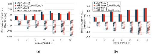
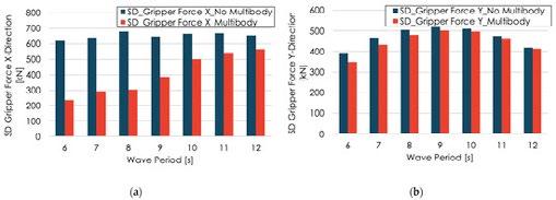
Figure 16 shows the gripper forces in the x and y directions. The forces are presented for Hs 2.5 m and wave heading of 180°. As can be seen, the multibody interaction has more effect on reducing gripper force in the x direction compared to the y direction. Figure 17 shows the standard deviation of gripper forces in x and y directions, respectively.
Figure 16. (a) Maximum gripper forces at the x direction, with and without multibody interaction; (b) Maximum gripper forces at the y-direction, with and without multibody interaction.
Figure 17. (a) Standard deviation gripper forces at the x direction, with and without multibody interaction; (b) Standard deviation gripper forces at the y direction, with and without multibody interaction.
Figure 18 shows results for the gripper forces in the x and y directions for different wave headings. The results show that the force in the x direction is more sensitive to the wave heading compared to the force in the y direction. Figure 19 presents the results of the vertical relative motion at MRP for different wave headings and significant wave heights. Figure 20 shows the results of the gripper forces for different significant wave heights. The results presented in Figure 16 to Figure 20 shall be used together with the onboard weather forecasted decision tool to further optimize the mating operation.
Figure 13 illustrates a comparison between the maximum and minimum relative motions at the motion reference point (MRP) for both the installation vessel and the spar. The mechanical gripper will function to compensate these motions to facilitate and ease the turbine mating operation. In addition to compensating for the relative motions between the installation vessel and the spar during the connection phase, it is also important to address the heave motion of the installation vessel during the lifting and mating phase of the wind turbine assembly.
This can be achieved by implementing a control system for the lifting grippers that compensates for the heave motion of the installation vessel, ensuring a safe and efficient mating operation.
Figure 18. (a) Maximum gripper forces at the x direction for different wave headings; (b) Maximum gripper forces at y direction for different wave headings (Hs 2.5 m and Tp 12 s).
Figure 13. (a) Minimum and maximum longitudinal motion at MRP, with and without multibody interaction, for Hs 2.5 m and wave heading 180° - LC1; (b) Minimum and maximum vertical motion at MRP, with and without multibody interaction, for Hs 2.5 m and wave heading 180° - LC1. Figure 14. Wave surface elevation including multibody interactions, modelled in AQWA. Figure 15. Wave surface elevation spar only, modelled in AQWA.Figure 19. (a) Minimum and maximum Z-relative motion at MRP (Hs 2.5 m and TP 12 s); (b) Minimum and maximum relative motion for different Hs and Tp 12 s.
The main findings of this study can be summarized as follows:
Figure 20. (a) Maximum gripper forces at x direction for different wave headings; (b) Maximum gripper forces at y direction for different wave headings (Heading 180 deg and Tp 12 s).
Figure 21 shows the effect of the wind and current on the gripper forces. Two blade pitch angles, 0 and 90 degrees, respectively, were considered. As can be seen, an increase in the gripper forces in the x and y directions were observed. The wind and current has more effect on the gripper force in the x direction compared to the gripper force in the y direction. Moreover, the effect of wind on the gripper forces is higher when the blade pitch angle is 0 degrees, compared to a blade pitch angle of 90 degrees.
• Offshore wind turbine installation concept: The study proposes a new method for installing offshore wind turbines using a floating vessel. The concept involves the use of a numerical model that includes a floating vessel, a spar foundation, a mechanical gripper, and mooring lines.
• Monitoring and positioning phases: The study focuses on the monitoring and positioning phases that precede the mating of the wind turbine assembly. These phases are crucial for ensuring a successful installation process.

• Multibody interactions: The study explores the impact of multibody interactions on the installation process. It demonstrates that these interactions have a substantial effect on reducing relative motions and gripper forces within a specific range of wave periods (6 - 9 s). However, their influence becomes negligible as the wave period increases.

• Relative motion: The relative motion between the wind turbine and the spar at the mating point is identified as a critical factor in the success of the mating operation. The study determines that this relative motion is primarily influenced by the first-order motions and is particularly sensitive to the significant wave height and wave peak period. However, it is found to be less affected by wind and current conditions.
Figure 21. (a) Maximum gripper forces at x direction, including wind and current for blade pitch angles of 0 and 90 degrees, respectively; (b) Maximum gripper forces at y direction, including wind and current for blade pitch angles of 0 and 90 degrees, respectively.
Considering the mooring layout and wave headings illustrated in Figure 11, it is anticipated that lines 1 and 3 will endure higher loads compared to line 2. The top tension in line 1 at β = 180 deg, Hs of 2.5 m, and Tp of 12 s, is studied here. Figure 22 presents the dynamic top tension for three conditions: wave only; wave, wind and current for blade pitch angle of 0 degrees; and wave, wind, and current for blade pitch angle of 90 degrees.
As can be seen in Figure 22, the mooring line tension has increased due to wind and current effects. Furthermore, it is worth noting that the mooring line tension experiences a significant increase when the blade pitch angle is set to 0 degrees, as compared to when it is set to 90 degrees.


• Blade orientations: Two blade orientations, with blade pitches of 90 degrees and 0 degrees, respectively, are considered in the study. It is observed that the choice of blade pitch has an impact on low-frequency motions and mooring line tensions. Specifically, the 0-degree blade pitch leads to a greater increase in the tension forces compared to the 90-degree blade pitch. Gripper forces, on the other hand, show less sensitivity to blade orientation angles.
• Gripper forces and hydraulic cylinder capacity: The study finds that the resulting gripper forces are within reasonable limits for compensation. These forces can be utilized to determine the appropriate hydraulic cylinder capacity for relative motion compensation during the installation process.
• Vessel heading optimization: The study highlights the importance of vessel heading optimization in minimizing relative motions and gripper forces between the installation vessel and the floating spar. For example, the gripper forces in the x direction are more sensitive to wave heading compared to the y direction. This optimization can facilitate the mating operation and reduce the impact force. Decision support tools, such as the Octopus system, are suggested for monitoring weather and vessel motions, providing accurate information on how incoming weather conditions may affect the operation execution. These tools can guide offshore crew in the optimization process.
You can find the complete article on mdpi.com/2077-1312/11/7/1373
“We experienced this first hand at Ørsted,” wrote Mads Nipper Group CEO early September on social media. In case you missed his inspiring words, read the post of this courageous leader below.
“The development in our American offshore wind market is working significantly against us and our entire industry, and we had to flag the risk of a significant impairment in three major offshore projects - projects that we had the courage to win several years ago in an entirely new market for offshore. And projects that as a result of very tough market developments now result in significant adversity - despite amazing work from our US based team. Because the most recent adverse market developments come in the form of rising interest rates and unexpected delays in our supply chains, and other challenges outside our direct control.”
“As a global leader in our industry we naturally and understandably face very sharp scrutiny and reactions in the stock market and the media. And severe adversity combined with unexpected financial impacts like we experience now naturally create doubt and concern among investors, within the industry, and among the policymakers shaping the conditions for global transformation. It can even affect me momentarily after a week like that. But only in brief flashes. Because I know the world needs us to expand and scale renewable energy while keeping fossil fuels deep underground.”
“In times of adversity, one can turn to faith and hope - but it is only in courage and not hope that we must find new solutions. We must now, both within the Ørsted, in our industry and politically, take new and sometimes challenging decisions to overcome adversity. We simply MUST recreate the essential financial value creation of offshore wind projects to continue to attract the hundreds of billions needed to scale our industry - to play its key role in fighting climate change, create new jobs and ensure energy security.”
“In the hours following our announcement the other day, I also emphasized to everyone at Ørsted that we are now in a new era after many years of successful transition from black to green energy during a favourable and relatively predictable decade.”

“Now, the world, in every way, is more unpredictable. It means that individuals and organizations, in addition to being skilled, must also have an even greater ability to adapt to radically and constantly shifting market conditions, and to bounce back quickly when knocked down.”
“And exactly that is what we can and will do in Ørsted!”
DEZE PAGINA’S BEVATTEN NIEUWS VAN VAN IROBRANCHEVERENIGING
VOOR DE NEDERLANDSE TOELEVERANCIERS IN DE OFFSHORE ENERGIE
INDUSTRIE EN HAAR LEDEN.
GENOEMDE ACTIVITEITEN ZULLEN ALLEEN DOORGANG VINDEN BIJ VOLDOENDE BELANGSTELLING VANUIT DE LEDEN.
HEEFT U INTERESSE IN DEELNAME OF VRAGEN OVER:
> BEURZEN NEEM CONTACT OP MET JEROEN TRESFON, J.TRESFON@IRO.NL
> HANDELSMISSIES NEEM CONTACT OP MET TJERK SUURENBROEK, T.SUURENBROEK@IRO.NL
> CURSUSSEN NEEM CONTACT OP MET BARBARA VAN BUCHEM, B.VANBUCHEM@IRO.NL
> OVERIGE ZAKEN NEEM CONTACT OP MET IRO, VIA INFO@IRO.NL OF TELEFOONNUMMER 079-3411981.

Hieperdepiep hoera, ons ‘kind’ young iro is 5 jaar geworden!
5 jaar waarin zij grote stappen hebben gezet om de jonge generatie van onze industrie verbinding te laten maken, te inspireren en ideeën en nieuwe innovaties te delen om zo een toekomstbestendige en duurzame industrie te creëren.
Vrijdag 8 september hebben zij dat groots gevierd. Lees hier de terugblik en bekijk de foto’s Op naar de volgende 5 jaar!
Het ‘Global Energy Outlook’ event, dat op 6 september plaatsvond in het Maritiem Museum Rotterdam, leverde diverse vergezichten op.


Neil Golding en Richard Brakenhoff namen ons mee in de wereld van productie en consumptie van energie (fossiel & renewable) –nu en in de toekomst. We zijn er nog lang niet met het vinden van alternatieven voor olie & gas en lopen tegen veel obstakels aan. Uitdagingen te over, waar we met z’n allen de schouders onder moeten zetten. Kijk hier voor de presentaties en foto’s.
ALGEMENE LEDENVERGADERING BIJ HUISMAN19 OKTOBER – ALLEEN VOOR IRO LEDEN
IRO
BOOMPJES 40 (WILLEMSWERF) 13TH FLOOR 3011 XB ROTTERDAM
P.O. BOX 390 3000 AJ ROTTERDAM
T: +31 793411981
E: INFO@IRO.NL
I: WWW.IRO.NL
Joris Teer van The Hague Centre of Strategic Studies geeft een presentatie over de laatste geopolitieke ontwikkelingen en de effecten hiervan op de economie en op de levering van kritische grondstoffen en specifieke onderdelen die essentieel zijn voor de energietransitie. Kijk hier voor aanmelden en meer info.
Thema: visie voor de maritieme positie van Nederland in een veranderende wereld
De maritieme brancheverenigingen IRO, KVNR, NMT en de Vereniging van Waterbouwers organiseren op dinsdag 7 november a.s. het Groot Maritiem Verkiezingsdebat in Rotterdam Ahoy, waar op dat moment de beurs Europort plaatsvindt. Graag heten we je welkom op hét politiek maritieme debat van het jaar!
Op 22 november vinden de Tweede Kamerverkiezingen plaats en de verkiezingsprogramma’s staan vol maritieme aandachtspunten. Tegelijkertijd ontbreekt het aan urgentie om echt door te pakken.
Prominente kandidaat Tweede Kamerleden gaan daarom op 7 november a.s. onder leiding van Twan Huys (bekend van VPRO Buitenhof, NTR College Tour) met elkaar in gesprek over de betekenis van de maritieme sector voor Nederland.
Welke visie dragen zij uit voor de maritieme positie van Nederland in een wereld waar energietransitie, duurzaamheid en klimaatadaptatie ‘on top of mind’ staat? Hoe zien zij hun rol in deze maatschappelijk opgave?
Onderstaande topics worden hierbij belicht:
1. Nederlandse onafhankelijkheid vanuit eigen kracht
2. Energietransitie is geen keuze
3. Externe dreiging omzetten in maritieme kansen
4. Zonder mensen met de juiste vaardigheden geen schepen
Voorlopig programma
16:00 Ontvangst
16:30 Groot Maritiem Verkiezingsdebat
18:00 Netwerkborrel
19:30 Einde
Locatie
Rotterdam Ahoy
Dock 1, 2e verdieping
Ahoyweg 10
3084 BA Rotterdam
Aanmelden
Meld je uiterlijk 26 oktober a.s.
aan voor het Groot Maritiem Verkiezingsdebat op www.kvnr.nl/gmv23. Let op: je dient je ook apart hier als bezoeker van Europort aan te melden (verplicht).Graag tot ziens op dinsdag 7 november 2023. Het belooft een inspirerende middag te worden! DEZE PAGINA’S BEVATTEN NIEUWS VAN VAN IROBRANCHEVERENIGING VOOR DE NEDERLANDSE TOELEVERANCIERS IN DE OFFSHORE ENERGIE INDUSTRIE EN HAAR LEDEN.
De Young IRO Board zal het komende jaar een van de columnisten zijn van de Maritiem Courant, met wisselende pen.
De aftrap is voor Ruben de Jong. Ruben de Jong is werkzaam als scheepsontwerper bij Damen Shipyards. Hij is daarnaast Board Member bij Young IRO, de jongerenorganisatie van IRO:

Onlangs stuitte ik op een artikel in het Dagblad van het Noorden waarin het volgende stond geschreven: Jongeren moeten maar weinig hebben van een bedrijf als Shell. De klimaatbewuste generatie ziet zichzelf niet werken bij het oliebedrijf.
Zelf maak ik ook deel uit van deze klimaatbewuste generatie en ik herken het sentiment uit gesprekken met leeftijdsgenoten. Jonge mensen willen in hun werk graag ‘iets doen met duurzaamheid’ of bijdragen aan een duurzamere wereld. Een carrière bij een bedrijf dat actief is in de olie- en gas industrie lijkt een no-go.
Toch zou ik jongeren willen aanmoedigen om juist eens na te denken over een baan in de energie-industrie, daar vallen ook bedrijven onder die momenteel actief zijn in de olie en gas. Het zijn juist deze bedrijven met hun jarenlange ervaring, die de grote stappen zullen moeten maken in de energietransitie. Hier zijn veel ambitieuze jonge mensen voor nodig, die met een verfrissende blik de bedrijfscultuur en strategie kunnen, en willen, veranderen. Voor wie direct impact wil maken in de energietransitie, is het in mijn ogen logisch om te starten bij bijvoorbeeld de ‘renewables-afdelingen’ van bedrijven die momenteel verantwoordelijk zijn voor het grootste deel van onze energievoorziening.
De huidige energievoorziening is een complex systeem. De energietransitie is nog vele malen complexer. We hebben daarom mensen nodig die deze complexiteit overzien en verbanden kunnen leggen tussen maatschappelijke, economische en technologische ontwikkelingen. Waarschijnlijk zullen de bedrijven die nu onze energievoorziening voorzien en deze kennis hebben, ook de energietransitie mogelijk maken. Ik hoop van harte dat jonge mensen hieraan blijven willen bijdragen en dat de klimaatbewuste generatie niet aan de zijlijn komt te staan.
IRO organiseert van 6-9 mei 2024 weer het Nederlandse paviljoen op de Offshore Technology Conference (OTC)!


Met de geplande offshore windparken in de Golf van Mexico belooft het een interessante editie te worden.
Boek hier je stand (exclusief voor IRO leden)!
Van 26-29 augustus 2024 vindt de 50e editie van ONS plaats in Stavanger, Noorwegen. Een jubileum!

Nu de Noorse regering zwaar investeert in hernieuwbare energie, zal deze beurs in het teken staan van de energietransitie met een mix van alle soorten offshore-energie, carbon capture en waterstof. IRO zal een Nederlands Paviljoen hosten in hal 5, één van de hoofdhallen. Kijk hier voor meer informatie over prijzen en aanmelden.
Europort is al decennialang dé vakbeurs en ontmoetingsplaats waar de internationale maritieme industrie samenkomt om te netwerken, verbinden en innoveren.

De volgende editie van Europort is van 7-10 november 2023 in Rotterdam Ahoy.

IRO is supporting partner. Registreer je gratis voor een bezoek.
OFFSHORE ENERGY 2023 - 25% KORTING
Mis deze kans niet en registreer je hier meteen voor de Offshore Energy Exhibition & Conference op 28 en 29 november 2023 in Amsterdam. Gebruik de code IRO_DISCOUNT om je korting te claimen.

Waar blinken jullie in uit?
Onze kracht is trekken en hijsen met een kleine voetafdrukletterlijk en figuurlijk. Wij verhuren voornamelijk lineaire lieren. Onze lieren zijn compact, relatief licht en verbruiken weinig energie.
Omdat we een grote range hebben aan machines zijn we betrokken bij diverse projecten. Zo worden onze 800 Tons lieren ingezet voor landfalls en pipepuls van enkele kilometers terwijl een 35 Tons lier bijvoorbeeld kan worden ingezet voor het binnenhalen van een umbilical.
Wat trok jullie over de streep om lid te worden?
Wat een leuke zinsspeling: we zijn getrokken door het grote netwerk van professionele mensen die bij IRO werken en erbij zijn aangesloten. Ik ben van mening dat het lidmaatschap veel mogelijkheden biedt als het gaat om het bezoeken van beurzen en het leggen van nieuwe connecties. Bij Bezemer zijn we altijd op zoek naar nieuwe strategische partnerschappen waarbij we de inzetbaarheid van onze assets en technologie kunnen vergroten.
Wat hebben jullie de andere leden te bieden?
Wij trekken als een ‘tierelier’! Dat beschrijft ons het best.
IRO heeft recentelijk Bezemer als nieuw lid mogen verwelkomen. In een persoonlijk interview met Jurgen de Prez, Commercieel Directeur, maken wij kennis met lierleverancier Bezemer.
Daarnaast streven we ernaar om de meest veilige en betrouwbare leverancier te zijn in onze markt. We kijken er naar uit om met andere IRO leden te spreken over wat er speelt in de offshore sector en hoe wij kunnen bijdragen aan oplossingen voor de energie transitie. We hebben bijvoorbeeld een concept ontwikkeld waar we samen met mede IRO lid ALP Maritime Services kijken naar het intrekken van zware ankers voor offshore floating wind; waarbij wij een lineaire lier op hun schip installeren waarmee we een hogere kracht kunnen opwekken dan de bollard pull (in NL: paaltrek).
Hoe draagt Bezemer bij aan de energietransitie? Zoals gezegd door het ontwikkelen van oplossingen met anderen voor de uitdagingen van de toekomst. Vaak hebben de vraagstukken grote overeenkomsten met die van uit de vroege olie en gas dagen. Met bewezen technologieën kunnen we oplossingen hergebruiken.
Wij hebben onze eerste stappen gezet in de hernieuwbare energie voor het trekken van een export kabel voor het Hollandse Kust project; verder gebruiken we onze kennis en technologie in offshore floating wind installaties.


Op 16 oktober aanstaande organiseert Nederland Maritiem Land (NML) van 14.00-17.00 uur een voorlichtingssessie over de uitvoering van het Maritiem Masterplan. Deze voorlichtingssessie staat open voor bedrijven en instellingen in de maritieme sector en daarbuiten, die een rol kunnen en willen spelen bij de realisatie van het Maritiem Masterplan.
Kijk hier voor meer info over het programma en aanmelden.
DEZE PAGINA’S BEVATTEN NIEUWS
VAN VAN IROBRANCHEVERENIGING
VOOR DE NEDERLANDSE
TOELEVERANCIERS IN DE OFFSHORE ENERGIE INDUSTRIE EN HAAR LEDEN.
OSBIT
WWW.OSBIT.COM
Osbit is gespecialiseerd in ontwerp en levering van equipment voor efficiente installatie en onderhoud van Offshore Wind projecten.
Op 17 november organiseert de Koninklijke Nederlandse Redding Maatschappij (KNRM) voor de zesde keer het bijzondere evenement ‘Captain of Sales’.

Een dag lang strijden teams zij aan zij in een wedstrijd om het meeste geld op de halen voor de KNRM. De winnaar wordt Captain of Sales. Heb je een warm hart voor de KNRM en ben je dol op uitdagingen? Kom dan in actie en beleef een geweldige KNRM ervaring, samen met de KNRM vrijwilligers. Meld je hier snel aan!
NETWERKEN OP DE BEURSVLOER - NETHERLANDS PAVILIONS
Klik op de links voor meer info over de beurzen, prijzen en aanmeldformulieren. Of neem contact op met Jeroen Tresfon via j.tresfon@iro.nl.
• ADIPEC ABU DHABI, 2 - 5 OKTOBER
• EUROPORT ROTTERDAM, 7 - 10 NOVEMBER
• OEEC AMSTERDAM, 28 - 29 NOVEMBER
• OTC HOUSTON 2024, 6-9 MEI
• GLOBAL OFFSHORE WIND, 18-19 JUNI
IRO
BOOMPJES 40 (WILLEMSWERF)
13TH FLOOR
3011 XB ROTTERDAM
P.O. BOX 390
3000 AJ ROTTERDAM
T: +31 793411981
E: INFO@IRO.NL
I: WWW.IRO.NL
• SEOGS PARAMARIBO 2024, 24-27 JUNI
• ONS STAVANGER 2024, 26-29 AUGUSTUS
Naast de beurzen waar IRO een Nederlands paviljoen organiseert, hebben wij ook contacten met externe partijen omtrent de organisatie van diverse wereldwijde evenementen. Neemt u gerust contact op met IRO als u vragen heeft over internationale evenementen die niet in de beurskalender vermeld staan. Voor meer informatie, raadpleeg www.iro.nl/calendar
‘OFFSHORE ENERGIE: VAN FOSSIEL NAAR
DUURZAME ENERGIE’, INCLUSIEF BEZOEK
AAN UNIEKE
OFFSHORE EXPERIENCE
Inhoud cursus
• Cursus voor niet-technische medewerkers of nieuwkomers in de olie- en gasindustrie
• De achtergrond van de exploratie, productie en distributie van olie & gas
• Een breed overzicht van het mondiale speelveld van olie & gas en haar actoren
• De steeds groeiende wereldwijde behoefte aan energie, en de manier om daarin te voorzien met oude en nieuwe vormen van energie
• Hoe ziet het huidige en toekomstige offshore energielandschap rond de Noordzee eruit
• De energietransitie: mogelijke offshore oplossingen, bijvoorbeeld offshore wind- en golfenergie
• Actieve deelname aan de Offshore Experience in het Maritiem Museum Rotterdam
Locatie: Maritiem Museum Rotterdam
Prijs: €625,- excl. BTW (Het cursusgeld is inclusief lesmateriaal en lunch)
Voertaal: Nederlands
(Engels indien Engelstaligen in de cursus)
Tijd: 08.30 - 17.00 uur
Beschikbare data 2022:
• 13 december
Check de online IRO kalender voor meer informatie en aanmelden.
(foto: Marco de Swart)
2 OKTOBER ADIPEC NETWERKRECEPTIE ABU DHABI
2 - 5 OKTOBER ADIPEC ABU DHABI
4 OKTOBER WINDENERGY INDIA CHENNAI
19 OKTOBER ALGEMENE LEDENVERGADERING BIJ HUISMAN SCHIEDAM
25 - 26 OKTOBER OCEAN ENERGY EUROPE CONFERENCE & EXHIBITION (OEE2023) DEN HAAG
7 NOVEMBER GROOT MARITIEM VERKIEZINGSDEBAT TIJDENS EUROPORT ROTTERDAM
7 - 10 NOVEMBER EUROPORT ROTTERDAM
21 NOVEMBER NMT-IRO NETWERK EVENT BIJ HUISMAN SCHIEDAM
28 - 29 NOVEMBER OFFSHORE ENERGY AMSTERDAM
6 DECEMBER LOL BIJEENKOMST BIJ HSM OFFSHORE SCHIEDAM
7 DECEMBER BESTUURSVERGADERING N.T.B.
13 DECEMBER CURSUS OFFSHORE ENERGY: VAN FOSSIEL NAAR DUURZAME ENERGIE ROTTERDAM

10 JANUARI IRO NIEUWJAARSRECEPTIE DEN HAAG
5 FEBRUARI FLOATING WIND SOLUTIONS HOUSTON, VS 6
OTC HOUSTON HOUSTON, VS
GLOBAL OFFSHORE WIND MANCHESTER,
VOOR DE MEEST ACTUELE INFORMATIE, CHECK DE ONLINE IRO CALENDAR BOVENSTAANDE ACTIVITEITEN ZULLEN ALLEEN DOORGANG VINDEN BIJ VOLDOENDE BELANGSTELLING VANUIT DE LEDEN.


