
2024 | NORTHWEST THE OFFICIAL PUBLICATION OF THE NORTHWEST CHAPTER OF THE NORTH AMERICAN SOCIETY FOR TRENCHLESS TECHNOLOGY VINTAGE UNDERDRAIN CONDITION ASSESSMENT IN WINNIPEG, MANITOBA SPRING/SUMMER Return Undeliverable Canadian Items to: 2020 Portage Ave, Winnipeg, MB R3J 0K4 PM #40065075 BORE TO CONFIRM HDD FEASIBILITY THE USE OF A GEO-PILOT


Go Trenchless with PVC™
Engineered for Horizontal Directional Drilling (HDD) and other trenchless applications, TerraBrute® CR is a 100% non-metallic, AWWA C900 PVC pressure pipe system. Non-corroding and installation friendly, TerraBrute CR allows you to standardize on PVC throughout your municipal infrastructure.

ipexna.com IPEX by Aliaxis
4”
24”
in TerraBrute® CR is manufactured by IPEX Inc. TerraBrute® CR is a trademark of IPEX Branding Inc.
–
Available
The North American Society for Trenchless Technology (NASTT) is now accepting abstracts for its 2025 No-Dig Show in Denver, CO at the Colorado Convention Center March 30-April 3, 2025. Prospective authors are invited to submit a 250-word abstract outlining the scope of their paper and the principal points of benefit to the trenchless industry.
The abstracts must be submitted electronically by June 30, 2024 on the NASTT website:
The No-Dig Show is owned by the North American Society for Trenchless Technology (NASTT), a not-for-profit educational and technical society established in 1990 to promote trenchless technology for the public benefit. For more information about NASTT, visit our website at nastt.org.
for
SUBMISSION DEADLINE: JUNE 30, 2024
Call
Abstracts
nastt.org/no-dig-show


BACK TO CONTENTS MESSAGE FROM THE NASTT-NW CHAIR 7 MESSAGE FROM NASTT 8 ADVERTISER PRODUCT & SERVICE CENTRE 30 DEPARTMENTS: THE OFFICIAL PUBLICATION OF THE NORTHWEST CHAPTER OF THE NORTH AMERICAN SOCIETY FOR TRENCHLESS TECHNOLOGY
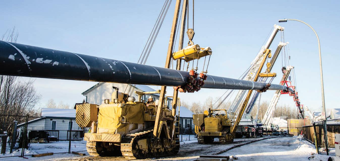
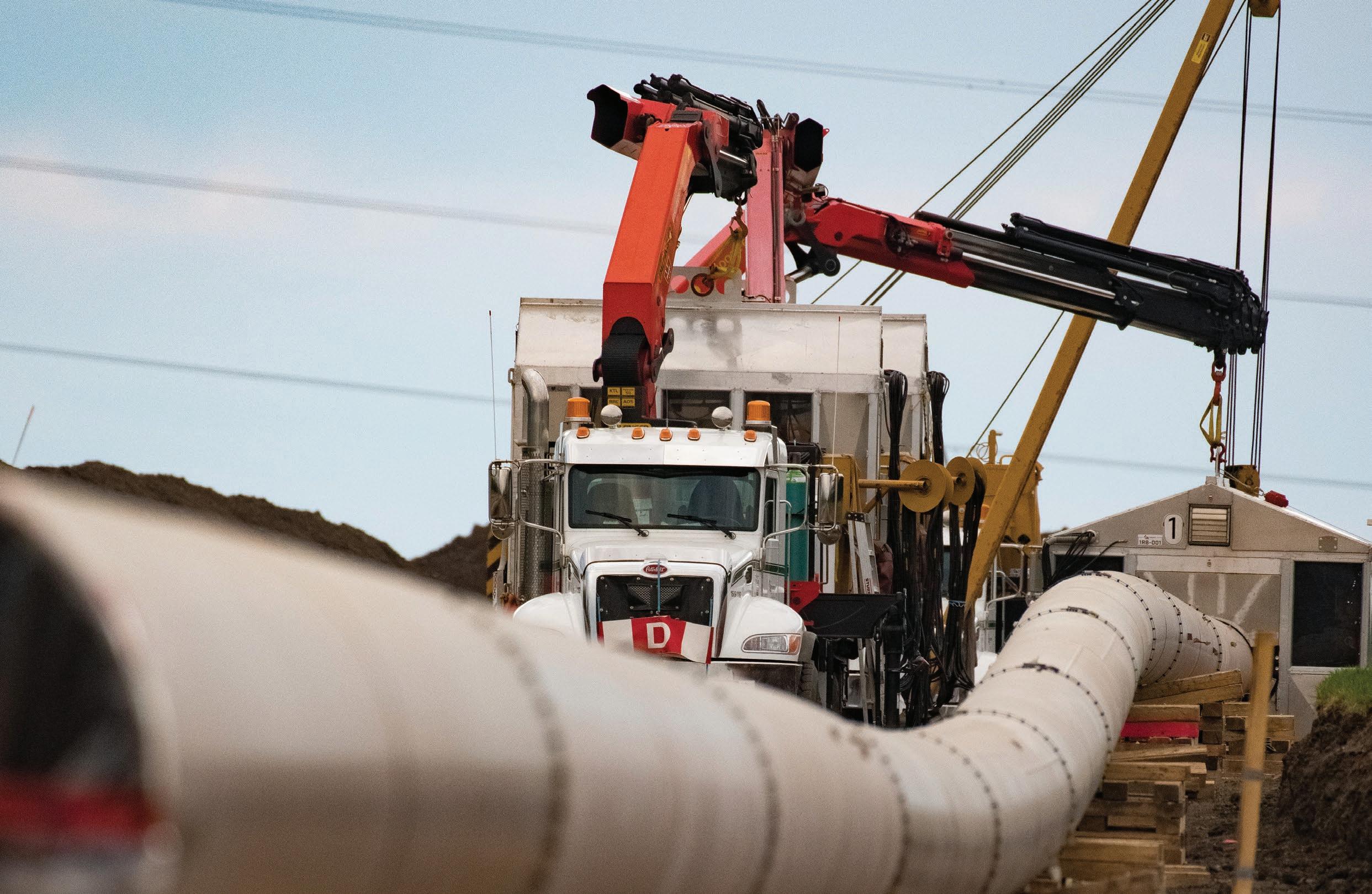
ON THE COVER: Pipeline construction Edmonton Alberta Canada | dreamstime.com 2024 | NORTHWEST THE OFFICIAL PUBLICATION OF THE NORTHWEST CHAPTER OF THE NORTH AMERICAN SOCIETY FOR TRENCHLESS TECHNOLOGY VINTAGE UNDERDRAIN CONDITION ASSESSMENT IN WINNIPEG, MANITOBA SPRING Return Undeliverable Canadian Items to: 2020 Portage Ave, Winnipeg, MB R3J 0K4 PM #40065075 BORE TO CONFIRM HDD FEASIBILITY THE USE OF A GEO-PILOT www.kelman.ca Managing Editor: Julia Waterer Design/Layout: Dia Chea Marketing Manager: Chad Morrison Advertising Coordinator: Stefanie Hagidiakow ©2024 Craig Kelman & Associates Ltd. All rights reserved. The contents of this publication, which does not necessarily reflect the opinion of the publisher or the association, may not be reproduced by any means, in whole or in part, without the prior written consent of the Northwest Chapter of the North American Society for Trenchless Technology. NASTT-NW BOARD OF DIRECTORS CHAIR GEORGE BONTUS Aegion Corporation PAST CHAIR SHANE COOPER AECOM VICE-CHAIR RAVEN SHARMA City of Selkirk TREASURER KEITH MOGGACH Royal Building Products SECRETARY CHAOSHI HU EPCOR DIRECTOR ALI BAYAT University of Alberta DIRECTOR CRAIG PASS Associated Engineering MAGAZINE COMMITTEE RAVEN SHARMA City of Selkirk Return Undeliverable Canadian Items to: 2020 Portage Ave, Winnipeg, MB R3J 0K4 Publication Mail Agreement #40065075 10 NASTT-NW. COM VIEW US ONLINE 4 NASTT 2025 CALL FOR ABSTRACTS 9 NASTT MEMBERSHIP 10 THE USE OF A GEO-PILOT BORE TO CONFIRM HDD FEASIBILITY 19 VINTAGE UNDERDRAIN CONDITION ASSESSMENT IN WINNIPEG, MANITOBA 26 2024 NASTT-NW CHAPTER BUYERS’ GUIDE 19 NASTT-NW.COM | 5
2024 | NORTHWEST
Shaping Our Shared Future
Associated Engineering specializes in trenchless design and construction. We provide communities with sustainable and resilient solutions. Our expertise includes horizontal directional drilling, micro-tunnelling, slip-lining, direct pipe, cased crossings, and pipe rehabilitation technologies. For information, contact Jason Lueke, National Discipline Leader, Trenchless, at luekej@ae.ca.
BACK TO CONTENTS
www.ae.ca www.precisecrossings.ca S pru c e Grove, Alberta | P. (780) 962.6882 | Toll Fr ee . (866) 96 2.6882 experienced in all types and sizes of crossings Environmental Sensitive Area Crossings Rivers | Creeks | Ravines certificate of recognition latest technology in navigation systems committed to safety and to our environment equipped with 110,000 lbs to 440,000 lbs capacity drills 6 | NASTT-NW JOURNAL | Spring/Summer 2024
THE IMPORTANCE OF CONTINUED EDUCATION
Construction season is approaching, and we expect that this will be a busy year in the trenchless industry. The NW Chapter has been busy over the fall and winter, with No Dig North in Edmonton in October and several technical luncheons presented in Edmonton and Calgary. No Dig North was a pleasant surprise, setting a new attendance record, with over 800 registrants. We had many great guest presentations, and were happy to share with all the attendees the arctic blast that hit during the show. It was an eyeopener for many.
Since then, the NW Chapter has been planning and delivering educational sessions including monthly technical luncheons in Edmonton and Calgary, and a Trenchless Seminar in Winnipeg. We’ve seen a wide range of trenchless topics presented at the luncheons. The Winnipeg Seminar was originally planned as an activity for the Red River College (RRC) Student Chapter, and evolved into a session where trenchless practitioners were also invited. These events provide a great opportunity for networking among trenchless practitioners.
The NW Chapter has two Student Chapters, with the University of Alberta championed by Dr. Ali Bayat, and the RRC chapter championed by Raven Sharma. Both of these champions recognize the value of educating not only the young people coming into our industry, but also the current practitioners. The NW Chapter, as well as NASTT, are working hard to include students in local activities, as well as sponsoring attendance at local and national events.
The need for continued education related to the trenchless industry is highlighted on a regular basis as we see projects designed and tendered that
include ambiguous or erroneous designs and specifications. The NW Chapter is planning to expand the opportunities for education for our members and all others involved in trenchless technologies. Our membership and volunteer base has traditionally been strongest in Alberta, with interest in Winnipeg, Saskatoon and Regina.
We have a great base of knowledge within our region, including industry-recognized experts in a wide range of trenchless technologies and systems, including NASTT certified instructors, that can provide state of the art information. Our Board is working on means to bring these resources to our members. We expect to offer both NASTT hosted courses, as well as homegrown sessions like the RRC seminar. With the advent of No DIG North, which will be
rotated through the three Canadian Chapter regions, our Board is pursuing potential opportunities to reestablish in-person training and networking opportunities in years when No Dig North is outside the NW Chapter area. 2024 will be a busy and exciting time for our Board and members. The key to success for our Chapter is a strong membership and volunteer base. As always, we welcome any volunteers to help plan educational and networking opportunities. Please visit our website, or contact any of our Board members to investigate options to join us in our journey.
George Bontus, P.Eng. Chair, NASTT Northwest Chapter
MESSAGE FROM THE NW CHAIR
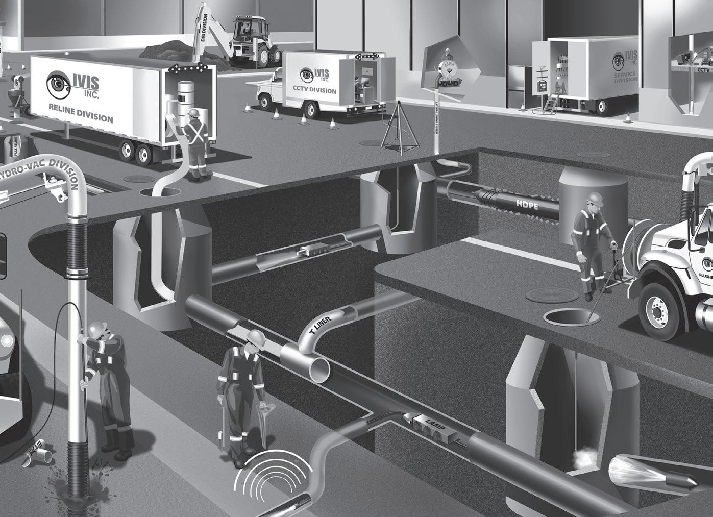
1-866-976-2626 www.ivisconstructioninc.com The Right People, The Right Equipment, The Right Choice Servicing the Underground Infrastructure Since 1996 • Maintenance Programs • Secondary Utility Locates/GPR
High pressure flushing/vacuum
CCTV
inspections of sewer lines
Lift Stations-maintenance & refurbishing
Hydro excavating utilities, piles, trenching
High Rail Unit for hydrovac, flushing, vacuum
Pipe bursting/open cut sewer replacement
of sewer lines,
lines, laterals,
lines Residential • Commercial • Municipalities • Industrial YOUR ONE STOP SHOP NASTT-NW.COM | 7 BACK TO CONTENTS
•
•
(camera)
•
•
•
•
• Relining
storm
T-liners, manholes and lift stations and potable water
FileName:22-1649_CA_Ad_Resize_NorthWest_Trenchless_Journal_UTT_CA-EN
Job#: 22-1649
Artist: Simon Tremblay Email: stremblay@mapei.com
Date: April 4, 2022 3:08 PM
Page Size: 4,625" x 7"
Number of Pages: 1
Bleed: No Amount: Colors: CMYK Process
KEEP AN EYE OUT FOR UPCOMING OPPORTUNITIES
Proven Technology for Underground Construction
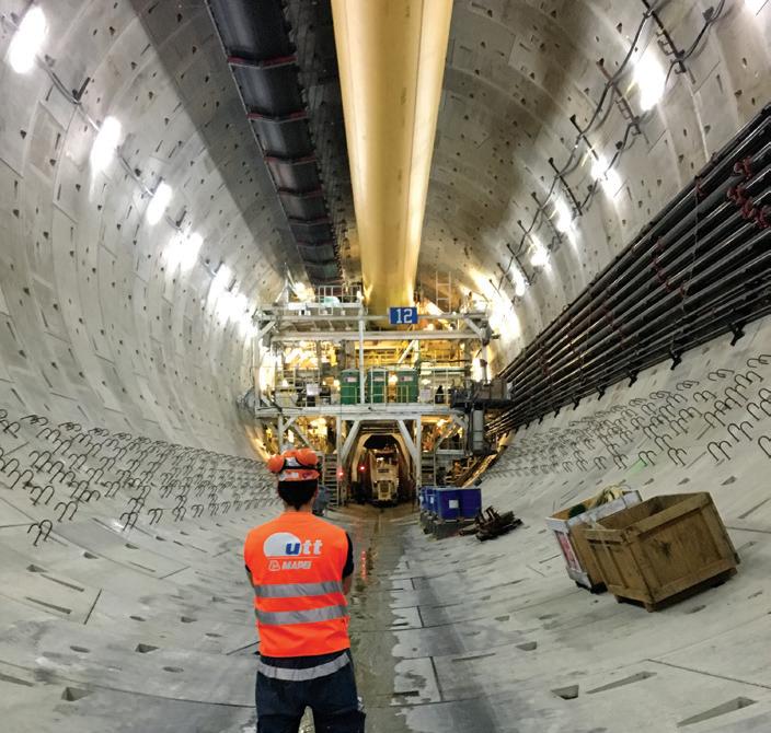
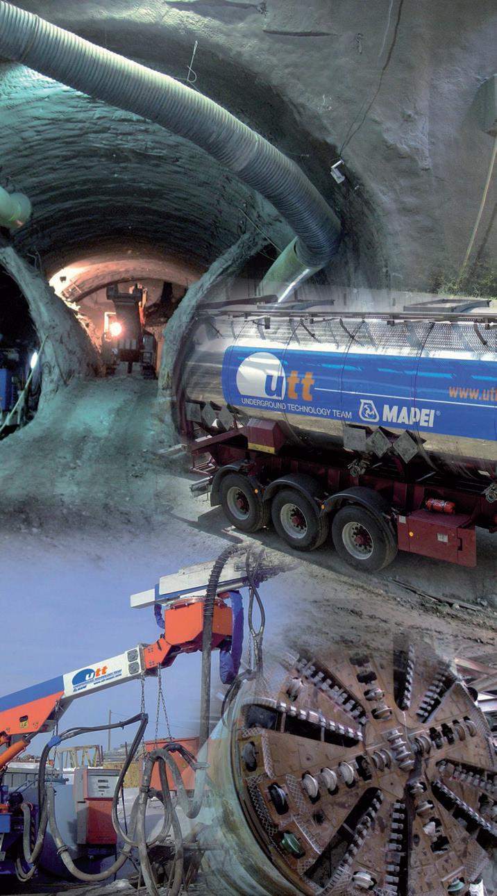
Our commitment is the detail that makes the difference.
Reliable technology and expertise for underground construction
Alkali-free set accelerators and admixtures for shotcrete
• Products for mechanized tunneling
• Products for grouting and consolidation
• Products for the repair, protection and coating of concrete
• Products for waterproofing
Discover the world of MAPEI: Underground Technology Team utt.mapei.com hq.utt@utt.mapei.com 1-800-426-2734 (1-800-42-MAPEI)
e’re riding high on the success of the NASTT 2024 No Dig Show, held recently in Providence, RI. It was a great week of networking with colleagues and learning about the latest advancements in trenchless technology as well as celebrating our successes and our many dedicated volunteers.
Looking ahead, we have another exciting event on the horizon: No Dig North 2024 in Niagara Falls this October 28–30. This promises to be an exceptional opportunity to delve deeper into the latest advancements, best practices, and emerging trends in our industry. Early registration is already underway, so I encourage you to secure your spot and take advantage of the discounted rates. Visit nodignorth.ca for all the details!
In addition to our upcoming conference, we have a lineup of virtual courses and chapter events planned in the coming months, including brand new updates to our cured-in-place pipe (CIPP) and horizontal directional drilling (HDD) good practice courses. These sessions will provide valuable learning experiences and networking opportunities for our members. Keep an eye out for announcements and mark your calendars to ensure you don’t miss out on these enriching opportunities. Visit nastt.org/training/upcoming-events for the latest updates.
I’m excited to carry forward the momentum and spirit of collaboration that defined the 2024 No Dig Show in Providence. Together, we can make a lasting impact in our industry.
Thank you once again for your support and dedication. I look forward to seeing you all at an upcoming training, conference or chapter technical luncheon.
Matthew Wallin, PE NASTT Chair
MESSAGE FROM NASTT
W
NOTE: COLORS VIEWED ON-SCREEN ARE INTENDED FOR VISUAL REFERENCE ONLY AND MAY NOT MATCH THE FINAL PRINTED PRODUCT.
1144 E. Newport Center Dr. Deerfield Beach, FL 33442
INFO SPECS 22-1649_CA_Ad_Resize_NorthWest_Trenchless_Journal_UTT_CA-EN.indd 1 2022-04-06 14:10:44 8 | NASTT-NW JOURNAL | Spring/Summer 2024 BACK TO CONTENTS
Con
Connnect t Lear n Achieve Inf
nn ect t Lear n Achi
NASTT membership equips and empowers you to thrive in your career. Join to be part of an elite community of trenchless professionals!
Connect • Learn Achieve • Influence
NASTT membership equips and empowers you to thrive in your
NASTT membership equips and empowers you to thrive in your Join to be part of an elite community of trenchless professionals!
Join to be part of an elite community of trenchless professionals!
Career Advancement Doors Opened!
Opened!
NASTT membership equips and empowers you
Join to be part of an elite community of trenchless
Career Advancement Doors
Opened!
Career Advancement Doors

Career Advancement Doors Opened!
Career Advancement Doors Opened!
Because of NASTT, I have a pretty stacked tool belt that helps me bring innovative approaches to infrastructure concerns. My experiences with trenchless technologies gives me a ‘leg up’ over others. ~ Eric Schuler, PE, Onondaga County Department Water Environment Protection
Amazing Network
Career Advancement Doors Opened!
Because of NASTT, I have a pretty stacked tool belt that helps me bring innovative approaches to infrastructure concerns. My experiences with trenchless technologies gives me a ‘leg up’ over others. ~ Eric Schuler, PE, Onondaga County Department Water Environment Protection
Because of NASTT, I have a pretty stacked tool belt that helps me bring innovative approaches to infrastructure concerns. My experiences with trenchless technologies gives me a ‘leg-up’ over others.
Because of NASTT, I have a pretty stacked tool belt that helps me bring innovative approaches to infrastructure concerns. My experiences with trenchless technologies gives me a ‘leg up’ over others.
Because of NASTT, I have a pretty stacked tool belt that helps me bring innovative approaches to infrastructure concerns. My experiences with trenchless technologies gives me a ‘leg up’ over others. ~ Eric Schuler, PE, Onondaga County Department Water
~ Eric Schuler, PE, Onondaga County Department Water Environment Protection
Environment Protection
Education Second to None
Education Second to None
Education Second to
None
NASTT is far and away the leading educator and networking pool in the trenchless industry. If your company plays a part in the trenchless industry, you will benefit from NASTT membership much more than you realize.
~ Eric Schuler, PE, Onondaga County Department Water Environment Protection
~ Joe Lane, Aegion Corp.
NASTT is far and away the leading educator and networking pool in the trenchless industry. If your company plays a part in the trenchless industry, you will benefit from NASTT membership much more than you realize. ~ Joe Lane, Aegion Corp.


Education Second to None
Tops at Staying on Top of the Industry
Environment Protection
Education Second to None
NASTT is far and away the leading educator and networking pool in the trenchless industry. If your company plays a part in the trenchless industry, you will benefit from NASTT membership much more than you realize.
~ Joe Lane, Aegion Corp.
NASTT is far and away the leading educator and networking pool in the trenchless industry. If your company plays a part in the trenchless industry, you will benefit from NASTT membership much more than you realize.
Tops at Staying on Top of the Industry
NASTT is far and away the leading educator and networking pool in the trenchless industry. If your company plays a part in the trenchless industry, you will benefit from NASTT membership much more than you realize. ~ Joe Lane, Aegion Corp.
I first joined NASTT to stay current on technological developments, best practices and market trends. Participating in NASTT committees and events and accessing its expert mentors and professionals is essential to the success of almost any project.
Education Second to None
Tops at Staying
~ Marya Jetten, Jacobs Engineering Group
on Top of the Industry
Joe Lane, Aegion Corp.
I first joined NASTT to stay current on technological developments, best practices and market trends. Participating in NASTT committees and events and accessing its expert mentors and professionals is essential to the success of almost any project. ~ Marya Jetten, Jacobs Engineering Group
Tops at Staying on Top of the Industry
Amazing Network
NASTT has been the most significant hicle relative to the industry connections I’ve made and throughout my career.
Amazing Network
NASTT has been the hicle relative to the industry connections I’ve made throughout my career.
Amazing Network
Amazing Network
Membership Helps Me My Stuff
NASTT has been the most significant vehicle relative to the industry-specific connections I’ve made and cultivated throughout my career.
Because of NASTT, I have a pretty stacked tool belt that helps me bring innovative approaches to infrastructure concerns. My experiences with trenchless technologies gives me a ‘leg up’ over others. ~ Eric Schuler, PE, Onondaga County Department Water
I first joined NASTT to stay current on technological developments, best practices and market trends. Participating in NASTT committees and events and accessing its expert mentors and professionals is essential to the success of almost any project. ~ Marya Jetten, Jacobs Engineering Group
~ Cindy Preuss, PE, CDM Smith
~ Cindy Preuss, PE, CDM
NASTT has been the hicle relative to the connections I’ve made throughout my career.
NASTT has been the most hicle relative to the industry connections I’ve made throughout my career.
I would not be doing what without the presence and impact NASTT. I wanted the industry about a record HDD project gave me the access and opportunity tell to the industry. ~ Jim Murphy, UniversalPegasus International
~ Cindy Preuss, PE, CDM Smith Membership Helps Me Strut My Stuff I would not be doing what I love to do without the presence and impact of NASTT. I wanted the industry to know about a record HDD project and NASTT gave me the access and opportunity to tell to the industry.
~ Cindy Preuss, PE,
~ Cindy Preuss, PE, CDM Membership Helps My Stuff
~ Jim Murphy, UniversalPegasus International
Membership Helps My Stuff I would not be doing without the presence NASTT. I wanted the about a record HDD gave me the access and tell to the industry. ~ UniversalPegasus International
Membership Helps My Stuff I would not be doing without the presence NASTT. I wanted about a record HDD gave me the access tell to the industry.
NASTT is far and away the leading educator and networking pool in the trenchless industry. If your company plays a part in the trenchless industry, you will benefit from NASTT membership much more than you realize. ~ Joe Lane, Aegion Corp.
I would not be doing what without the presence NASTT. I wanted the about a record HDD project gave me the access and tell to the industry. ~ UniversalPegasus International
Join as an individual or group savings as an organization with a corporate or government/ education/utility membership.
Join as an individual group savings as organization with corporate or government/ education/utility membership.

Join as an individual or get group savings as an organization with a corporate or government/education/utility membership.
Join as an individual group savings as
BACK TO CONTENTS NASTT-NW.COM | 9
UniversalPegasus
t
eve In
n ect
Lear n Achi
nastt.org/membership membership@nastt.org |
Infl ue
Connnect t Lear n
Achieve
Tops at Staying on Top of the Industry I first joined NASTT to stay current on technological developments, best prac-
Join as an individual group savings as an organization with MEMBERSHIP nastt.org/membership Connn ect t Lear n Achi eve Infl NASTT membership equips and empowers you to thrive in your Join to be part of an elite community of trenchless professionals! Join to be part of an elite community of trenchless professionals!
MEMBERSHIP NASTT membership equips and empowers you to thrive in your career. nastt.org/membership membership@nastt.org 888-388-2554 “ “ “ “ “ ” ” ” ” ”
THE USE OF A GEO-PILOT
BORE TO CONFIRM HDD FEASIBILITY
James Murphy, M.Eng. P.Eng., Universal Pegasus International, Calgary, Alberta
Dan Costello, M.Sc. (Hons), P.Geo., PMP. BGC Engineering Inc., Vancouver, BC
Marty Zaleski, M.Sc., P.Geo, CEG, LEG. BGC Engineering Inc., Vancouver, BC
ABSTRACT
Within the Trenchless Program for the Trans Mountain Expansion Project, almost 50 Horizontal Directional Drills (HDDs), as well as all the other trenchless methods were utilized. However, due to severe topography and access constraints, there were locations where a geotechnical investigation with a normal number of boreholes would not be able to provide sufficient geotechnical information, and even a limited number of holes would be cost prohibitive. Boreholes in some cases would have been hundreds of meters deep with difficult access and site preparation. Also, from a design standpoint, engineering would primarily be interested in whether there are fractures that would be major fluid loss zones or there would be fractures or faults that would produce water that would likely fail the HDD. Therefore, for two long ‘potential’ NPS 36 HDD crossings in mountainous terrain, Universal Pegasus offered up the potential for doing ‘geo-pilot bores’ to confirm the
feasibility of using HDD in these locations. From a regulatory perspective, a geo-pilot bore following the HDD design profile is considered part of the geotechnical program provided it does not exit and stops short by 50 metres or more. Exiting the bore would constitute ‘construction’ which has significant restrictions and reporting issues.
A successful geo-pilot bore approximately 1,700 m (5,600 ft) long confirmed the feasibility of the first HDD crossing at Dry Gulch in August of 2021 and a second geo-pilot bore for the Mountain Crossing #3 HDD crossing, approximately 1,600 m (5,300 ft) long HDD was completed in 2022. This paper describes the design, thinking, and construction challenges behind the geo-pilot bore concept with these two examples.
INTRODUCTION
The Trans Mountain Expansion Project (TMEP) is the largest, most technically challenging pipeline project ever constructed
in Canada and possibly in North America and is currently valued at over 30 billion (CAD). This project consists of 987 km (613 miles) of NPS 36 and PS 42 pipeline, 11 pump stations, three marine berths, addition of 19 petroleum storage tanks, and elevation changes not normally designed for in a liquids pipeline. The challenges are many and diverse. With similar challenging projects like Keystone XL being cancelled, TMEP stands out in that this challenging project is under construction now with completion planned for late 2023.
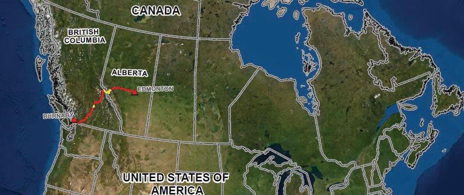
The pipeline runs from Edmonton, Alberta to Burnaby, British Columbia, carrying dilbit (diluted bitumen) to the port of Vancouver in Burnaby. For the most part, the route follows the existing Trans Mountain Pipeline (TMPL) route other than a few relatively short sections such as along the Coquihalla River where TMEP follows a different route to avoid geohazards or other constraints. Figure 1 shows the TMEP route.
Construction of the original TMPL was completed in 1953, connecting the Edmonton
BACK TO CONTENTS This paper was presented at the NASTT 2023 No Dig Show in Portland, Oregon April 30 – May 4, 2023 10 | NASTT-NW JOURNAL | Spring/Summer 2024
refineries and terminal to the offload point at Kamloops, BC, Sumas, BC and the Westridge Terminal in the Burrard Inlet, a total of approximately 1,150 km (715 miles). This pipeline was constructed as an NPS 24 line to carry approximately 300,000 barrels per day (bpd).
TMEP will result in the looping (or twinning) of the existing TMPL system between Edmonton and Burnaby terminals with about 987 km (613 miles) of new buried pipeline. Most of the existing pipeline, along with two reactivated pipeline segments, will become Line 1. The proposed new pipeline segments, along with several existing active pipeline segments, will become Line 2. The Project will increase the capacity of the existing TMPL system from 47,690 m³/ day (300,000 bpd) to 141,500 m³/d (890,000 bpd) of crude petroleum and refined products.
GEOGRAPHY
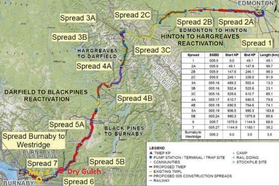
The pipeline route begins in Edmonton and traverses west through the Alberta Plains (Figure 2). The Alberta Plains are characterized by low topographic relief with glaciolacustrine and till sediments overlying poorly lithified sedimentary bedrock. The pipeline crosses three different mountain ranges, the Rockies, Columbia, and Cascade mountains. They are characterized by high topographic relief with colluvial, till and bedrock exposures on the valley walls and thick sequences of fluvial and glaciofluvial sediments in the bottom of valleys. Between the Columbia and Cascade mountains, the pipeline traverses the extensive Interior Plateau. The Interior Plateau is characterized by moderate topographic relief with colluvial, fluvial and glacial sediments overlying metasediment and volcanic bedrock. Finally, the route spans the lowlands of the Fraser River Valley before ending at the Westridge Terminal in Burnaby, BC. The Fraser Valley is characterized by low topographic relief with fluvial and glacial sediments.
The TMEP pipeline elevation profile is shown in Figure 3 with the approximate location of the two sites identified. Starting out at an elevation of 680 m (2,231 ft) at KP 0.0 (Baseline Road HDD) in Edmonton, the pipeline rises to an elevation of 1,229 m (4,032 ft) at KP 350 (near Hinton AB and the Hardisty Creek Geohazard HDD) before dropping to the central plateau with an elevation of approximately 400 m (1,312 ft) at KP 840 (Kamloops, BC and Thompson River HDD)
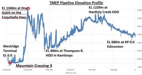
3. Pipeline Profile KP 0.0 to Westridge Terminal and then rising again to a peak elevation of 1,360 m (4,462 ft) at approximately KP 1000 (Dry Gulch HDD) then finally dropping to sea level at the Westridge terminal at the termination of the Burnaby Pipeline Tunnel.
This geography has presented numerous challenges which have been solved in many cases with the use of trenchless construction methodologies. Two of the more challenging crossings are the Dry
BACK TO CONTENTS NASTT-NW.COM | 11
Figure 1. Location of the Trans Mountain Expansion Project
Figure 2. TMEP Route Map
Figure
Gulch and Mountain Crossing 3. Both underwent significant review with various options being considered
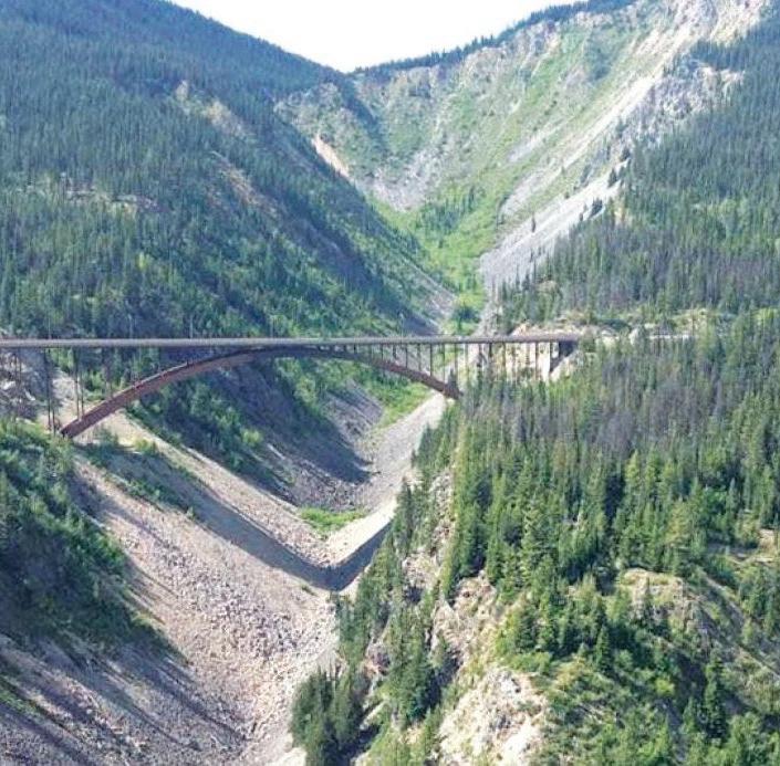
Dry Gulch HDD
The options considered for the Dry Gulch crossing shown in Figure 4 were, HDD, Open Cut, and Raise Boring. Some of the many challenges for the Open Cut and Raise Boring are primarily the crossing geometry and the hard bedrock, as well as practical access down to the bottom of the gulch and through the crossing. Ultimately the HDD option was considered to be the most acceptable construction methodology.
One major and possibly limiting consideration of an HDD at Dry Gulch was a technical need for extra heavy wall (EHW) pipe due to the depth of the HDD profile. On the Project, EHW pipe is only required on certain crossings for specific reasons, therefore a request for almost 1,800 m (5,906 ft) of additional EHW pipe was not going to be met. The project would not have this much contingency EHW pipe in inventory and the lead time for manufacturing and delivering this pipe would not have met the schedule. However, the idea of relocating EHW pipe originally scheduled for one of the other crossings was floated. This particular crossing was allotted the EHW pipe due to profile depth considerations. Once the pilot hole for the other crossing was completed and was an acceptable profile depth for the normal heavy wall (HW) pipe, the EHW pipe was able to be reallocated to the Dry Gulch crossing making the HDD a viable alternative for Dry Gulch.
Mountain Crossing 3 HDD
The primary options considered for Mountain Crossing 3 (approximately
2,300 m /7,546 ft in length), where a major reroute, a Drill and Blast tunnel, and an HDD. Ultimately the HDD was considered to be the preferred methodology.
Geo-Pilot Bore Methodology
The concept of a geo-pilot bore was first proposed by the author for challenging HDD crossings on the 1,177 km Enbridge Northern Gateway Project (Edmonton, AB and to Kitimat, BC). This project also had numerous potential HDDs in mountainous terrain. The author proposed doing geo–pilot bores to prove the feasibility of some HDDs and to use these bores as pilot holes if the crossing was considered feasible. Similar to the TMEP, a limited number of traditional geotechnical boreholes would not have been sufficient to provide a definitive HDD feasibility. The general concept for geo-pilot bores was accepted by the project team but the project was ultimately cancelled in 2014, and as such, the geo-pilot concept was not tested.
TMEP provided another opportunity to consider geo-pilot bores to prove feasibility. Both Dry Gulch and Mountain Crossing 3 are in very mountainous terrain. In both cases, consideration was given to the need for geotechnical information to assess the feasibility of construction options and BGC Engineering, Inc. (BGC), the geotechnical Engineers of Record for the project, wrote geotechnical feasibility assessment reports based on the expected geological conditions. It was expected that the primary construction concerns would be the influx of ground water and fractures that would cause significant drilling fluid circulation problems. It was also considered that traditional boreholes to investigate the middle of the profiles would need to be hundreds of metres deep and would only provide information regarding the potential for fluid loss or water ingress at the specific location of the borehole, which perhaps would not intersect critical features along the profile. Additionally, access and workspace for the drill rig would have been very challenging and expensive.
As an alternative to drilling multiple high-cost geotechnical boreholes, the author proposed doing geo-pilot bores along the planned HDD profiles/alignments. The benefit would be that the geo-pilot bores would provide a direct indication of HDD feasibility and could ultimately be utilized as the pilot holes for the crossing. The plan for these geo-pilot bores was to stop at a point where the required information was obtained, but the bore was at least 50 m short of the proposed HDD exit point. Stopping
the geo-pilot bores before the exit point was a regulatory requirement of the Canadian Energy Regulator (CER) to demonstrate that construction has not commenced. There was a three-month notification period in place prior to start of construction of any HDD crossing. Since the feasibility of the methodology had to be confirmed prior to construction start, the geo-pilot bores needed to stop short otherwise construction would have been considered ‘started’ by the CER.
One other complication in the design of the geo-pilot bore was the expectation that these two HDDs will be intersects. As such, a reasonable amount of straight tangent needed to remain to allow for an intersect. This was not too much of a problem on the Dry Gulch as it was drilled south to north with the north side having a long tangent. However, this was not as easy on the Mountain Crossing 3 as it was a longer HDD and the team wanted to intersect on the long horizontal tangent. Ultimately it was decided to plan for an intersect around the 1500–1600 m mark on the south side of the crossing.
GEOLOGY AT THE TWO CROSSINGS
To assist with the technical feasibility evaluation, rigorous and detailed desktop geological reviews were carried out for these crossings. These were done to assess if there were any potential faults along the alignment that might prove to be show stoppers.
Dry Gulch
Dry Gulch is located within the Coquihalla Range of the Cascade Mountains physiographic region (Holland, 1976). The Cascade Mountains are composed of folded and metamorphosed Paleozoic and Mesozoic sedimentary and volcanic rocks, intruded by Mesozoic granitic batholiths (Journeay et al., 2000; Monger, 1989).
Dry Gulch forms a tributary valley to Coquihalla River, near its headwaters. Both Dry Creek, and the section of Coquihalla River to which it reports, form steep-walled canyons flanked by bedrock cliffs, talus, and colluvium, with minor till.
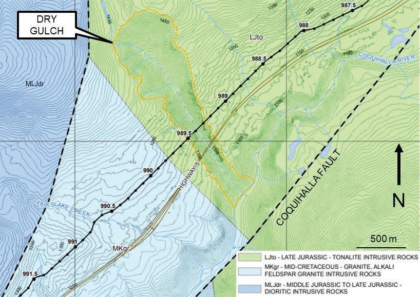
Near Dry Gulch, Coquihalla River flows southwest and follows the rightlateral Coquihalla fault, which offsets and is therefore younger than the nearby, Eoceneaged Needle Peak pluton (Monger, 1989). Near the crossing, it offsets mid-Cretaceous granite (Unit MKgr on Figure 5), Middle to Late Jurassic diorite (Unit MLJdr), and Late Jurassic granodiorite, gneiss, and tonalite (Unit LJto) of the Eagle Plutonic Complex
BACK TO CONTENTS 12 | NASTT-NW JOURNAL | Spring/Summer 2024
Fig. 4. Dry Gulch at Highway and Pipeline Crossing
(Monger, 1989; Ray, 1990; Cui et al., 2013).
An older, northwest- to north-trending fault forms the contact between diorite and tonalite, passing about 200 m west of the northern head of Dry Gulch. The HDD will pass through granite and tonalite, crossing a contact between the two about midway along its proposed bore path.
Dry Gulch forms an anomalously deep ravine in otherwise moderately-sloping upland terrain, despite an absence of a clear structural control. It is interpreted as having been formed by a subglacial outburst flood during the last glaciation, i.e., a jökulhlaup. The outburst flood produced over-steepened walls in a deeply incised ravine, which have been subject to rock slides and falls since deglaciation, producing coarse talus that mantles the slopes and lies at an approximate angle of repose (near 35°).
Mountain Crossing 3
Mountain Crossing 3 is located within the Skagit Range of the Cascade Mountains physiographic region (Holland, 1976). The topography is characterized by rugged mountain ranges, steeply incised tributary valleys, wide U-shaped main valleys, relict glacial landforms, terraces, fans, cones, steep slopes, fluvial plains and small basins. Steep upper slopes are rock- dominant with colluvium or till mantling the mid and lower slopes. Debris flows occur on many of the fans that infill the valley floors (Trans Mountain, 2013).
The Cascade Mountains are composed of folded and metamorphosed Paleozoic and Mesozoic sedimentary and volcanic rocks intruded by granitic batholiths (Journeay et al., 2000 and Monger, 1989). Bedrock mapped by Cui et al. (2013) indicates that the bedrock along the HDD crossing consists mainly of greenschist-grade mafic to intermediate volcanics of the Slollicum Schist Formation. Granodiorites of the Mount Barr Batholith are also mapped in the area.
Regional- and local-scale faulting, gravity deformation, and exfoliation jointing (particularly in the plutonic rocks) dominate the structural regime in this area (Savigny, 1991 and Monger, 1989). The most prominent local faulting is expressed at the surface as a set of distinct lineaments, prominent faces, gulleys, and steep-sided creek valleys up to several kilometres long, crossing the main mountain massifs. These major discontinuities are near-vertical, striking approximately northeast-southwest (striking within 45 degrees of the borepath alignment), and form a strong control on
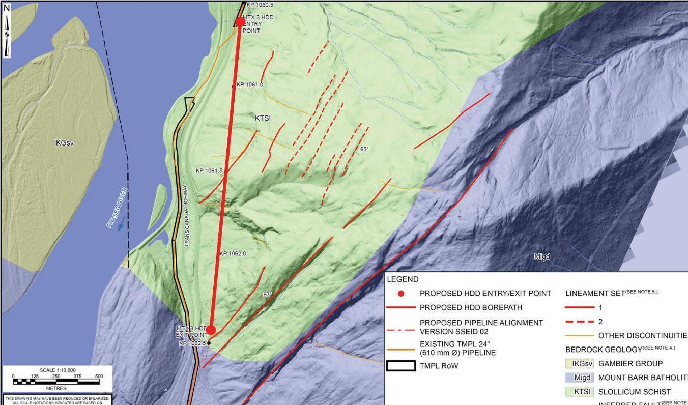
the topography and terrain (Set 1, Figure 6). These discontinuities are expected to persist to depths at or below valley-bottom elevation, and may be related to regional faulting, the presumed orientation of which aligns with the valley wall and borepath (e.g., the Vedder fault; Savigny, 1991). We expected that at borepath depth, these discontinuities are characterized by decimetre to metre-scale zones of fractured and altered bedrock, which could provide preferential flow paths for groundwater. The discontinuity sets were traced along their intersection with the ground surface and measured in three-dimensions, using a 3D surface model generated from lidar data.
Less prominent discontinuities (Set 2, Figure 6) on the slope include those associated with gravity deformation on the ridge above the proposed HDD. These are expressed as transverse antislope scarps, and are expected to persist to depths below surface of 20 m to 50 m. Other minor lineament sets are evident in the lidar, although none are expected to be present at depths greater than a few tens of metres below surface.
Minor flowing artesian pressures were recorded at the exit point, however due to the geometry of the borepath, high depth of cover (approximately 250 m) and surrounding topographic relief, groundwater pressures are expected to be higher along the borepath
BACK TO CONTENTS NASTT-NW.COM | 13
Fig. 5. Dry Gulch Geological Setting
Figure 6: Mountain Crossing 3 Bedrock geology and prominent structural lineaments.
than at the entry and exits (>100 m above the borepath in places). Groundwater inflows are expected to be significant, particularly in fault and fracture zones. Faults have the potential to host high groundwater pressures due to the potential for direct hydraulic connection to the ridgetop elevation approximately 1,200 m above the borepath elevation. The potential for significant lengths of high groundwater inflow from obliquely intersecting adverse structure, combined with an imbalanced bore profile, raise concerns with groundwater management and possible borepath instability in high hydraulic conductivity fault zones. These studies demonstrated the need for geo-pilot bores that could prove feasibility for the crossings. The go ahead was received from the project to proceed with the proposed geo-pilot bores.
CONSTRUCTION OF THE GEO-PILOT BORES
The drilling of the geo-pilot bores was considered to be very challenging and costly due to the challenging terrain and the necessity to prepare costly entry sites for the geo-pilot bores. The consideration was that the cost would be appropriate knowing that, if successful and feasibility is proven, this cost would be necessary in any case, to complete the HDD.
Dry Gulch
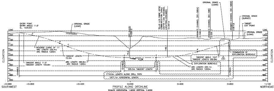
The Dry Gulch was the first geo-pilot bore to be drilled. Rig set up was completed in late August, 2021, and the exploratory geo-pilot bore was completed about a month later. The bore was also investigated using the gamma tool to see if additional information was obtainable. Gamma Ray logs can be used for identifying lithologies and for correlating zones. However, it was found that the formation was very consistent. The primary role of the geo-pilot bore was to determine if a loss zone was present and whether ground water flow was present. The geo- pilot bore was relatively uneventful with a total length of just over 1,700 m. The bore was completed using a TCI 12 ¼ inch tri-cone drill bit using a DD 440 drill rig. As seen in Figure 7, the bore was drilled from the high side for reasons of access primarily. No groundwater influx was encountered during the geo-pilot bore and no fluid loss zones were encountered. Spoils during the drilling process were very consistent with fine crushed rock.
The successful completion of the geo-pilot bore proved the feasibility of the Dry Gulch HDD along the profile planned. This was a major undertaking and the completion of
this HDD will be a major challenge. Casing installation on the crossings encountered large boulders, as expected, and confined space entry for drill and blast operations was
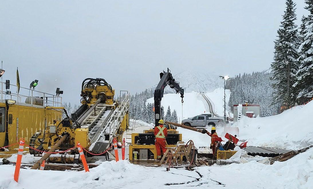
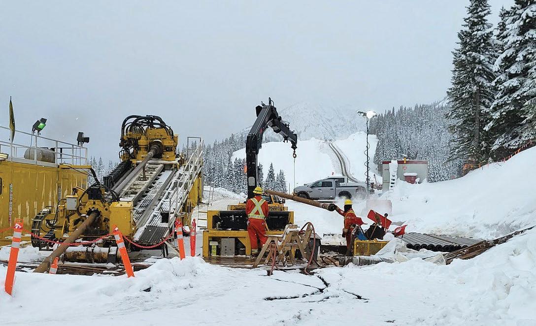
required on numerous occasions. The geopilot bore is just the first step in construction of the Dry Gulch HDD. The geo-pilot bore drill rig is shown in Figure 8. The challenging
BACK TO CONTENTS 14 | NASTT-NW JOURNAL | Spring/Summer 2024
Figure 8. Geo-Pilot bore rig (during reaming) with pipe lay down area in the background
Fig. 7. Dry Gulch Geo- Pilot Bore Profile
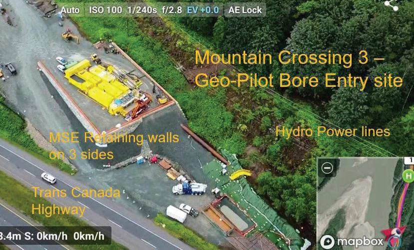
Fig. 9. Mountain 3 Geo-Pilot Bore Entry Site with casing
pipe lay down area for the 1800 m of pipe, is seen in the background. Many challenges are awaiting the team in 2023 as completion of the Dry Gulch HDD is planned for mid 2023. Five reaming passes are planned to achieve a 48-inch (122 cm) reamed hole due to the hard nature of the bedrock. The whole process, up to pipe installation, could take upwards of a year or more.
Mountain Crossing 3
Mountain Crossing 3 was the second geopilot bore to be drilled and was considered successful in the summer of 2022. This geo-pilot bore presented many water-influxrelated challenges. When water influx was encountered, drilling stopped while grouting of the section of bore was carried out. Since the pilot bore is the best, and possibly only, opportunity for grouting, the grouting effort was extensive and time consuming and was performed a number of times and in some cases was repeated at the same location. It was clear that the best time to grout was during the drilling of the geo-pilot bore. It was necessary to determine if grouting would be successful at cutting off the flow of ground water. Although considered successful, a small amount of flow still persisted. However, the time spent during the pilot bore drilling would pay off in the long run during the numerous slow reaming passes. Due to the coarse nature of the overlying soils, an extensive casing was required. This included boulders that had to be dealt with during the 60-inch (152.4 cm) diameter casing installation. A total of 84 m of 60-inch casing was needed to reach and be seated in the bedrock.
As seen in Figure 9, site construction had to deal with a number of constraints. The site is situated between a major four-lane highway, the slope of the mountain, and the power lines. In addition, the existing NPS 24, TMPL line 1 runs adjacent to the site. One will rarely see such a complex entry site.
During the drilling of the geo-pilot bore, the length was extended a couple of times to ensure that sufficient length was achieved to prove feasibility and to efficiently deal with the planned intersect. Originally planned for a length of about 1950 m, the ultimate
length of the geo-pilot bore ended up at 1600 m. The shorter length kept the intersect point on the horizontal tangent rather than on the exit tangent. Considering the limited alternatives available for the crossing, it was determined that the water influx, in the locations encountered, was something that would be manageable during the drilling and reaming process, after high pressure grouting during the pilot bore, although it is expected to be quite costly. This influx of groundwater created excess diluted drilling fluid which needed to be managed in accordance with project requirements. Ultimately, the plan has now included contracting a company to treat the water, close to the site, for the reaming and pipe installation phase of the project.
HDD CONSTRUCTION
Now that both of these crossings were confirmed feasible for the HDD trenchless construction methodology, completion of the pilot holes and reaming of the bores to the planned 48 inches (122 cm), commenced in 2022. Completion of these HDDs is planned for second quarter of 2023. Every aspect of these crossings is complex from access to intersect, lay down area, drag section construction, and pipeline installation. Considering the lengths of these installations and the importance to the Project of the successful installations, both of these crossing installs will include Herrenknecht thruster assist which further complicates the pullback arrangement. The laydown area itself, in tight constraints and mountainous terrain, requires extensive earthworks. For the dry gulch pull back plan, a detailed stress analysis was carried out to ensure that the forces on the pipe and equipment was fully understood and accounted for. In addition, a detailed execution plan for the pull back is required by TMEP. Completion of these crossings will be covered in future papers and presentations.
CONCLUSIONS
Based on the results obtained at the Dry Gulch and Mountain Crossing 3 crossings, the concept of a geo-pilot bore was likely the only practical means for determining the feasibility of the HDD methodology. The geo-pilot bores in these locations were
extremely expensive, in the multi millions of dollars, but considering they demonstrated the feasibility of the HDD methodology and that they were drilled on the planned HDD profile, the majority of the cost would have been required in any case. The fact that the pilot bores and the necessary site preparations were constructed, the overall crossing schedules for these crossings were positively impacted. For future HDDs we would recommend the use of geo-pilot bores for proving HDD feasibility in certain specific circumstances. These would be where typical geotechnical investigations are challenging to carry out and likely not going to produce adequate results.
REFERENCES
Cui, Y., Katay, F., Nelson, J.L., Han, T., Desjardins, P.J., and Sinclair, L. (2013). British Columbia Digital Geology. British Columbia Geological Survey, Open File 2013-04, Release 2.1.
Holland, S.S. (1976). Landforms of British Columbia: a Physiographic Outline. Bulletin 48, The Government of the Province of British Columbia.
Journeay, J.M., Williams, S.P., and Wheeler, J.O. (2000). Tectonic assemblage map, Vancouver, British Columbia GSC Open File 2948a. Geological Survey of Canada. Monger, J.W.H. (1989). Geology Hope Open File 41-1989. Geological Survey of Canada.
Ray, G.E. (1990). ‘The geology and mineralization of the Coquihalla gold belt and Hozameen fault system, southwestern British Columbia.’ Mineral Resources Division, Geological Survey Branch, Bulletin, ISSN 0226-7497; 79.
Savigny, W. (1991). Engineering Geology of Large Landslides in the Lower Fraser River Valley Transportation Corridor Southwestern Canadian Cordillera. Geological Engineering Program, Department of Geological Sciences, University of British Columbia, Vancouver.
Trans Mountain Pipeline ULC. (2013). Trans Mountain Expansion Project Application to the National Energy Board. Volume 4A – Appendix I: Route Physiography and Hydrology, dated November 28, 2013.
NASTT-NW.COM | 15
SAVE THE DATE FOR
THE 2024 NO-DIG NORTH

28-30, 2024 OCTOBER
No-Dig North will take place October 28-30, in Niagara Falls at the Niagara Falls Convention Centre.
The 2024 No-Dig North will feature two full days and four tracks of sessions as well as Good Practice Courses on the first day of the conference. The conference will also include an exhibit hall with over 120 exhibitors.

16 | NASTT-NW JOURNAL | Spring/Summer 2024
BACK TO CONTENTS NASTT-NW.COM | 17


BACK TO CONTENTS ® HANDS-FREE TECHNOLOGY Keep your crew safe with solutions that change how HDD work gets done. SAFE. PRECISE. PRODUCTIVE. LAVALLEYINDUSTRIES.COM ACCESS HDD TOOLS AND RESOURCES 18 | NASTT-NW JOURNAL | Spring/Summer 2024

This paper was presented at the2023 No-Dig Show in Portland, Oregon April 30 – May 4, 2023
VINTAGE UNDERDRAIN CONDITION ASSESSMENT IN WINNIPEG, MANITOBA
Christopher C. Macey, P. Eng. AECOM Canada Ltd, Winnipeg, Manitoba
Christopher Mitchell, B.Sc. (hons) AECOM Canada Ltd, Winnipeg, Manitoba
Paul Bortoluzzi, Project Coordinator, City of Winnipeg Water and Waste Department, Winnipeg, MB
ABSTRACT
The Branch I Aqueduct is 18.6 km (11.6 miles) of 1200 mm/ 1650 mm (48''/66'') of reinforced concrete pressure pipe that supplies about 40% of the City of Winnipeg, MB water daily. It was constructed from 1917–1919 in sulphate-rich soils prior to the advent of sulphate resistant cement. The pipes were very uniquely protected against sulphate related deterioration by installation of a small diameter clay tile underdrain system that functioned as a French drain. The system has been very effective at protecting the Aqueduct from exterior attack; however, its condition had never been assessed and it was built with very limited access to facilitate the insertion of inspection equipment.
This paper reports on the approach and challenges associated with assessing condition: from an access/equipment selection perspective and analytically in terms of how condition and rehabilitation requirements were rationalized. A French drain is inherently different than conventional pipe as infiltration is not a defect but an essential feature of the pipe to lower the groundwater table. While conventional National Association of Sewer Service Company’s (NASSCO) Pipeline Assessment Certification Program (PACP)i grading could be applied to characterize defects, the structural and O&M ramifications needed to be modified based on the pipe’s functional use and specific defects’ potential impact on deterioration of the underdrain pipe through loss of ground. Similarly, the approach to select appropriate rehabilitation treatments needed to carefully balance the need for the pipe to function as a French drain versus the need to minimize loss of ground processes that would initiate deterioration.
BACKGROUND
The Shoal Lake Aqueduct was constructed from 1913 to 1919 to supply water to the City of Winnipeg, and extended from Shoal Lake at the Ontario/Manitoba border to McPhillips Reservoir. The Aqueduct was largely referenced as a single entity until 1959, when the Branch II Aqueduct from Deacon Reservoir was constructed.
After 1959, the original Aqueduct alignment from Deacon Reservoir to McPhillips Reservoir became known as the Branch I Aqueduct and the remainder of the Aqueduct from Shoal Lake to the Deacon Reservoir as the Shoal Lake or Main Aqueduct. To put into perspective the value of the Branch I Aqueduct, its present-day replacement cost has been estimated at $440 million.
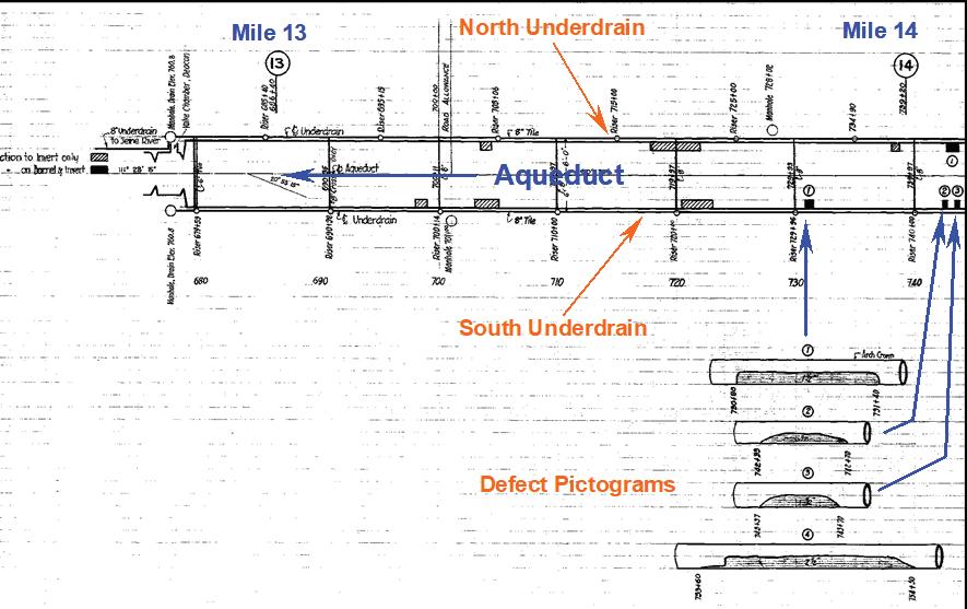
The Underdrain System was conceived and installed in response to early discoveries in the Aqueduct construction project of sulphate degradation to the concrete structure of the Main Aqueduct. Most notably documented in 1918, two years after construction of the A-Section of the Aqueduct, its lower quadrants were found to be exhibiting severe concrete deterioration due to sulphate attack as noted in Figure 1.
Sulphates in groundwater can interact with the cement- aggregate matrix to break down the concrete, essentially removing cementitious product, returning the mixture to a pile of gravel aggregate. While there wasn’t initially clear consensus on the true root cause, one
BACK TO CONTENTS NASTT-NW.COM | 19
Figure 1: Typical Mapping of Sulphate Damage on the A-Section of the Aqueduct, Circa 1918

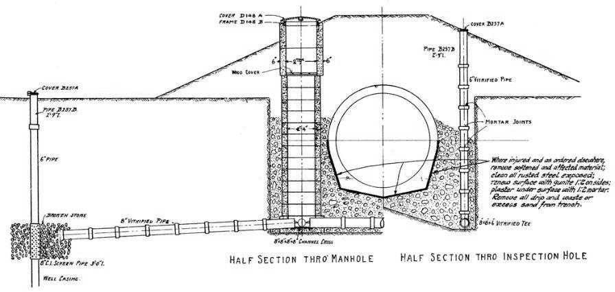
of the solutions proposed to mitigate sulphate attack at the time was to lower the groundwater level surrounding the concrete pipe using underdrains acting as a French drain system. Sulphates originate from the soil matrix and are dissolved into solution in the groundwater where they can interact with the concrete. By reducing the groundwater contact with the concrete, it was theorized that the Aqueduct could be protected from any further sulphate attack. The first underdrains were built on the A-Section as a retrofit in 1920 and 1921 (Figure 2). Studies undertaken in the Shoal Lake Aqueduct Assessment Program eventually confirmed that the underdrains constructed on the A-section were effective at largely limiting deterioration to extents documented in original 1918-1920 inspections in Figure 1.
INSPECTION OBJECTIVES FOR THE BRANCH I AQUEDUCT UNDERDRAIN SYSTEM
A primary objective of the project was to establish true condition ratings of the underdrain pipe system in terms of the Water Research Centre’s (WRC) Structural Performance Grade (SPG)ii where SPG values are rated from one to five with one is ‘like new’ and five
has failed or in a state of incipient failure. Rehabilitation treatment assignments for the 11.55 miles (18.6 km) of previously un-inspected 6-to-12-inch underdrains were determined from inspections utilized by CCTV methods only with no Multi-Sensor Inspection technologies used. The post-inspection analytical work would provide rehabilitation recommendations with associated work orders that would allow the development of a reactive repair or future Capital Works Programs and facilitate the long-range and strategic planning for the City’s Water and Waste Department. A breakdown of the system inspected by age, material type, and size is presented in Table 1 and Table 2.
Careful consideration was required to be given to post-process PACP codes during the analytical process particularly for Service Defect observations. Service Defects such as open joints or infiltration are inherent in the design and operation of an underdrain pipe and some structural defects such as circumferential fractures in clay pipe that would ordinarily be seen and considered for remediation as they are defects, may be acceptable to leave in an underdrain pipe. In an underdrain function, they can, in some cases be recognized as a positive feature that assists the system in functioning in its intended manner as a French drain. Therefore, the interpretation of standard PACP version 7.03 observations required some minor modifications in post-processing from conventional sewer to interpret the results of inspections adequately for the underdrain asset class.
INSPECTION TECHNOLOGY REVIEW
At the project development stage, current inspection technologies were considered for their availability, cost and capability to meet and surpass access, and negotiate difficult-to-traverse portions of the underdrain system. It was believed that portions of the underdrain system were built around thrust block structures having acute 45-degree bends to circumvent those structures, but also tap connections that were known to cross connect and drain into other systems, that may warrant lateral launch equipment. The following systems were reviewed for consideration:
BACK TO CONTENTS 20 | NASTT-NW JOURNAL | Spring/Summer 2024
Pipe Material (in feet) Installation Date Total (ft) Unknown 1918 1919 1992 2006 2007 2011 Unknown 126 42 46 214 Vitrified Clay 208 33 59,299 59,540 Concrete 417 417 Polyvinyl Chloride 123 190 376 144 833 Total 457 33 59,299 459 236 376 144 61,004
Table 1: Inspection Inventory Lengths (ft) by Material Type and Installation Date
Size Range (in inches) Material (%) Total (%) VCP Concrete PVC Unknown 6'' 17.7 0.3 18.0 8'' 58.8 1.1 0.1 60.0 10'' 19.0 19.0 12'' 0.7 0.1 0.8 Unknown 2.1 0.2 2.3 Total 97.6 0.7 1.4 0.4 100.0
Table 2: Percentage Inspection Assessment of Underdrain Pipe Diameter and Material Breakdown
THE CHALLENGE TO INSPECT A VINTAGE AQUEDUCT’S UNDERDRAIN PIPE SYSTEM FOR CONDITION ASSESSMENT IN WINNIPEG, MB CANADA
Figure 2: Underdrain Retrofit of the Aqueduct A-Section – Design
• PUSH ROD CAMERA SYSTEMS
Push rod camera systems such as the Ferret™ or similar are available in the inspection industry having wireless streaming technology. These systems are handheld devices that are able to inspect up to 36 feet (11 metres) in length. The ‘look see’ camera is designed for investigatory applications within buildings, small structures and conduits having a camera lens capable of 720p resolution and in colour, having adequate LEDs that are powered by internal batteries for up to seventy minutes per charge. On consideration for this application, these units would only be capable of effective inspection to 30 feet (9.1 metre) distances and governed by interconnecting rod count distances and were deemed ineffective for this project.
• PUSH CABLE CAMERA SYSTEM
The ‘Ridgid’ ©, See-snake or similar push type cameras have interchangeable self-levelling camera heads, color images with 656 x 492 resolution using LED lighting. Higher end units have pan and tilt technology capability where cable lengths are available for up to 300 feet (91.44 metres). A calibrated distance counter can determine distances to defects and features and are capable of achieving inspection distances of up to ~90 feet (27 metres) within pipe diameters up to 12'' (30.5 centimetres) as the lack of cable rigidity may limit larger diameter deployment. The push cable camera system can travel through 90° bends having guided brushes and train roller set ups that could extend inspections further. Further, Sonde technology can be attached for ground location requirements to assist in the underdrain alignment mapping; however, deep pipe will reduce the location accuracy. This system was acknowledged as a supporting tool to the mainline tractor in areas of difficult to access, small diameter acute bend environments but would lack the lateral launch capability.
MAINLINE TRACTOR CAMERA WITH PIVOT ARM CONFIGURATION
The industry standard mainline tractor set up with further improved capability using pivot arms for better lateral access requirements within the underdrain system such as the patented Polaris™ arm, that allows mainline cameras to bend around 90º bends without obstructed views. Other systems have guide proboscis that are seen on camera as they extend beyond the camera focal area. These systems also afford the use of the pan and tilt technology and are available within the North American pipe inspection industry however we determined that the local Canadian market did not have such equipment as the start-up costs were prohibitive for this type of work.
LATERAL LAUNCH MAINLINE TRACTOR CAMERA
This tractor platform has the capability of accessing mainline pipe capable of distances up to 1200 feet (365.8 metres) but can access laterals using its lateral launcher into 2-to-6-inch laterals or larger having capable distances of 150 feet (46 metres) or more. The lateral launched cable is the same mainline cable reel so is subject to and limited to the cable rigidity and lateral diameter. The lateral launch unit has the disadvantage of increased tractor length that could inhibit progression through acute bends that were likely to exist within the underdrain but could launch the camera within the mainline if need be. These systems afford the use of the pan and tilt technology and are available within the North American pipe inspection industry.
ADVANCED MAINLINE CAMERA MOBILITY SYSTEMS
Latest technologies show aspects of miniaturization and locomotion adaptations to overcome pipe arrangements and obstacles using rubberized belt-drive systems or ‘soft robot’ tractors featuring worm or caterpillar pneumatic/hydraulically driven pistons or bladder technologies. Used predominantly within the nuclear, gas or other high-risk environments, these miniaturized tractor units are extremely versatile, and able to travel around or over acute bends, offset joints and large obstacles. Specialized equipment comes with specialized supportive and control systems that may require additional vehicular platforms that would inherently increase costs to become financially prohibitive for this size of Contract. Furthermore, these units are derived from the European and East Asian markets where availability is limited in the North American market; with no known local dealer, no support and no known Contractor has these types of systems.
INSPECTION APPROACH AND METHODOLOGY
The intent of the Condition Assessment process is to attach a Condition Grade to each manhole- to-manhole section of underdrain pipe based upon the worst visible defects observed within the section. This is a two-step process involving the assignment of a preliminary Internal Condition Grade (ICG)ii or NASSCOs Quick Score Grading systemi based on defect scores calculated from underdrain inspection data, and then the assignment of a final Structural Performance Grade (SPG)ii based on a screening of the Quick Score with additional consideration of supplementary data such as soil conditions, frequency of surcharging, etc.
The Underdrain System differs from a conventional sewer main system in that the underdrain is designed to allow groundwater water to enter the pipe and lower the groundwater table as opposed to a conventional sewer main that is designed to be watertight. By design, the underdrain system is design to intentionally leak to lower the water table locally. This type of system is often referred to as a French drain, which is any type of drain that redirects surface water and/or groundwater away from an area. Early French drains were simple rock filled trenches to collect surface and groundwater. They are named after the American Agriculturist who invented them, Henry Flag French.
In modern day systems, French drains would use perforated pipe wrapped with a geotextile to protect against soil migration into the pipe. At the time of the Aqueduct construction, they simply used vitrified clay pipe without gaskets. While some drawings suggest the joints should be wrapped in burlap to mitigate against soil migration, there is very little evidence that was ever carried out, so some soil migration is inherent in the design of the system. This alteration in design purpose (e.g., allowing infiltration), however, impacts the significance of condition grades as occurrences of some defects such as infiltration are considered to be an attribute in an underdrain as opposed to an undesirable condition in a conventional sewer as long as the amount of soil migration is not contributing to excessive deterioration of the pipe structure.
Mild circumferential fractures are a good example of the above, as they are often a less serious defect than in conventional systems provided there is no loss of stability for the pipe. Cracks in the four quadrants of the top, bottom, and spring-line along with excessive ovality is considered an indication of a loss of structural stability as are visual loss of grade in the pipes. Pure circumferential cracks with no loss of grade can provide additional avenues for infiltration and groundwater lowering with only a limited loss of structural stability. Furthermore, while open and pulled joints are indicative of clear
BACK TO CONTENTS NASTT-NW.COM | 21
defects in a conventional system, they are inherent in the design of the underdrains and only a concern when excessive voiding occurs that could endanger the soil support required for the Aqueduct.
The conflicting objectives from conventional sewers were addressed in the following manner:
1. SPG’s were rationalized in the traditional manner, thereby flagging increased re- inspection frequencies as the long-term effects of increased soil migration would increase deterioration rates
2. Treatment or rehabilitation was only assigned if the defects were creating instability to the underdrain or an obvious loss of ground adjacent the Aqueduct.
INSPECTION LOGISTICS, PROGRESSION AND COMPLETION
Access to the underdrain system was a challenge in certain areas having the majority of the system running parallel to the Greater Winnipeg Water District’s rail system where access limitations were reviewed during the project development stage to identify equipment best suited for cleaning and inspection of the underdrain system having adequate vehicular access capability, hi-rail systems or third party City support help attain access to the underdrain assets and complete manhole inspections. It was also expected that in areas local to the Assiniboine and Red River that higher risk of collapses would be present in poor soils that would inhibit full inspection. Tender quantities for the installation of reactive or urgent manhole and external point repairs where the proponent would likely carry a subcontractor was considered but not carried forward however an increase in allowance for the higher quantity of reversal inspections to facilitate a full inspection was applied.
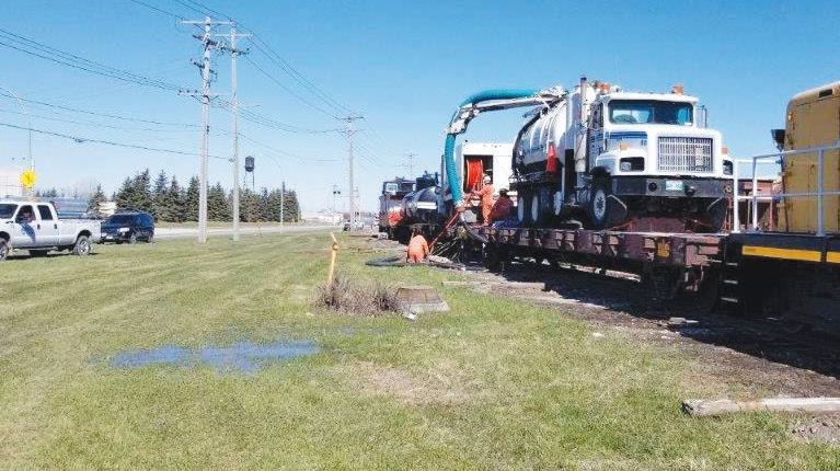
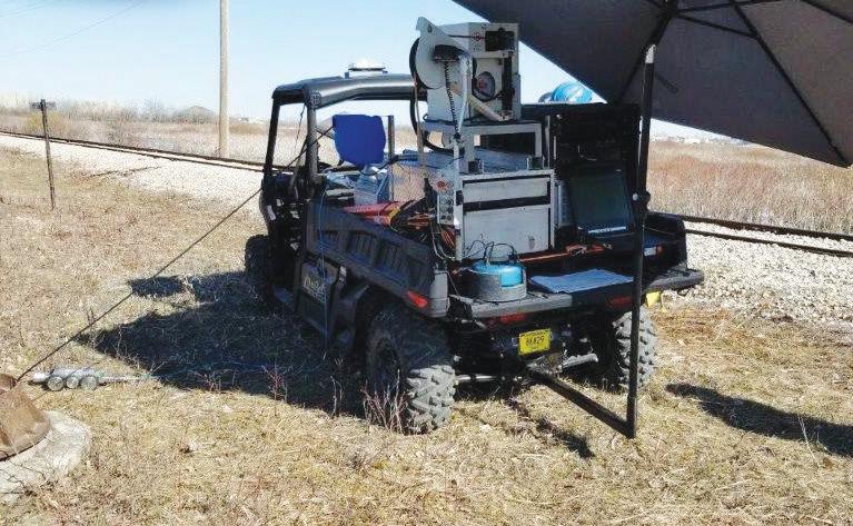
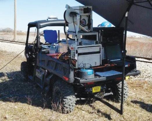
AECOM produced the Request for Proposal (RFP) and the work was awarded to Uni-Jet Industrial Pipe Ltd. (Uni-Jet), a local contractor to Winnipeg, for the cleaning and inspection of 61,004 feet (18,594 metres) of underdrain pipes. Uni-Jet mobilized sufficient plant and equipment onto vehicles that were suitable for urban and off-road environments where the use of the GWWD rail system was key to the mobilization of cleaning and inspection equipment while the manhole inspection equipment was transferred onto a modified 4x4 off-road vehicle (ORV).
The challenge of working with specialized inspection equipment became evident when camera equipment using the pan and tilt technology was successfully deployed within the urban areas, however, once mobilized onto the rail cart, the functionality of the pan and tilt technology was removed and panning to defects was not possible. This limiting functionality was not anticipated by Uni-Jet and communication efforts with the camera manufacturer provided no solution. It was agreed by all that the camera would slow down on the approach to significant defects that would ordinarily require panning, in the hopes that clearer imagery would be attained for adequate condition assessment and acceptance purposes.
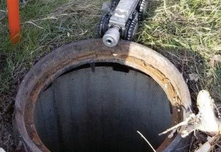
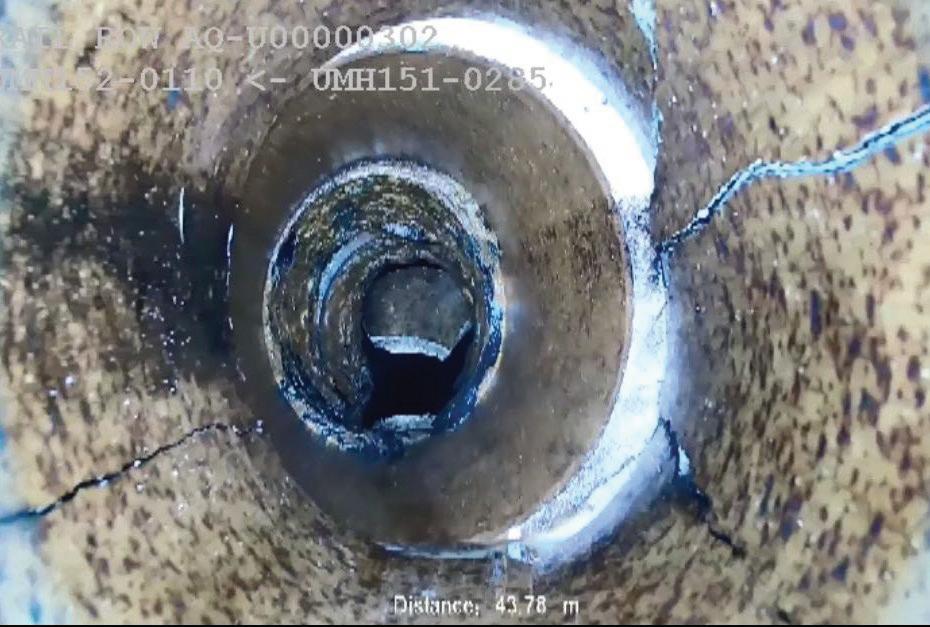
Cameras used were of good quality, a 4'' (10.2 centimetres) tractor was purchased that would be specifically used for this project and can be seen in Figure 3 and Figure 4; however, Uni-Jet’s lateral launch platform was not mobilized for this project. Imagery was of high-quality high definition (Figure 5), but again pan and tilt technologies were not available within the off-road, rail line and limited accessed environments.
BACK TO CONTENTS 22 | NASTT-NW JOURNAL | Spring/Summer 2024
Figure 3: Uni-Jet’s Equipment mobilized on the GWWD Rail cart
Figure 4: Manhole Panoramo Equipment placed onto an RV Unit
THE CHALLENGE TO INSPECT A VINTAGE AQUEDUCT’S UNDERDRAIN PIPE SYSTEM FOR CONDITION ASSESSMENT IN WINNIPEG, MB CANADA
Figure 5: Small Diameter 4'' Tractor Unit with HD Imagery
PROGRESS AND COMPLETION
Uni-Jet was able to complete most of the planned works on schedule with completed underdrain inspection distances of 58,845 feet (17,935 metres) of the total 61,004 feet (18,594 metres) that was planned, a total of 96% completion. Inspection progress was ahead of schedule; however, a number of assets could not be completed until fall drawdown of river levels to certain underdrain sections, particularly outfalls that were influenced by river levels. Uni-Jet’s contract began with the provision of two inspection crews and one manhole inspection crew having a peak daily inspection rate of 5,375 feet (1,638 metres), having the average inspection rate of 1,834 feet (559 metres) per day in comparison to the overall projection of 1,800 feet (548.7 metres) per day. Uni-Jet removed a total of 18.96 tons (17,200.2 kilograms) of debris from the underdrain or 1.74 tons/mile (980.8 kg/km) of inspected pipe where only localized areas had excessive debris. Sixteen segments were not fully inspected due to high water levels as a result of collapses, offset pipe joints and other conditions that resulted with 2,159 feet (658 metres) of uninspected distance within the total segment length of 4,318 feet (1316 metres) as seen in Figure 6. This would mean only 3.5% of the total inventory was not inspected. Otherwise, solid debris removal was not an issue and the majority of underdrains had completed reversals. Further, manhole inspections were of high quality with good imagery and acceptable coding with sufficient cleaning completed. Overall, Uni-Jet was able to complete the contract within the allotted thirty-five working day period to Substantial Performance and completed all deficiencies by the allotted forty-five working days to Total Performance.
UNDERDRAIN AND MANHOLE INSPECTION RESULTS
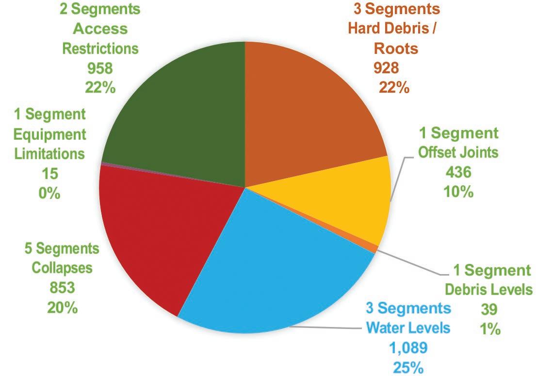
The percentage of underdrain sections with elevated SPG’s (i.e., 3, 4 or 5) was found to be very high as seen in Figure 7 and Figure 8. However, the nature of the treatments were almost exclusively localized deficiencies. Many of the deficiencies did not pose a distinct collapse risk for the pipe and actually aided in its prime function as a French drain (e.g., circumferential fractures and small holes with no loss of ground) and ere not assigned repairs but retained the high SPG for the segment to trigger re-inspections at an increased frequency. These are markedly different considerations and defect distributions
than are present in the more traditional combined, separate, and storm sewer networks. So, while the overall condition looks very poor at face value, the recommended repairs only total 433 feet of pipe, which is only 0.74% of the inspected length. So, the vast majority of the system by length is functioning well.
REHABILITATION TREATMENT ASSIGNMENT
For the underdrain system, not all driver defects with a severity of SPG 3, 4, and 5 were assigned treatments. Where defects such as mild circumferential fractures or small holes were not contributing to structural instability or a visible loss of ground, no treatments were assigned.
SPG values were not de-rated as the potential for further deterioration is higher, where it would warrant tighter re-inspection frequencies on a segment-by-segment need. The requirement for manhole treatment was rationalized independently of the underdrain pipes, as many of the manhole defects were initiating loss of ground around the chamber and the Aqueduct. For the underdrain system, full length trenchless technologies would eliminate the French drain effect of the pipe though short lengths of Trenchless Point Repairs (TPR’s) or isolated locations of stabilization would not.
BACK TO CONTENTS NASTT-NW.COM | 23
Figure 6: Distribution of Incomplete Inspections by Affected Segment Length
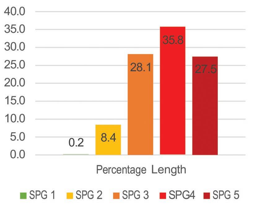
Figure 7: SPG Values by Percentage Length
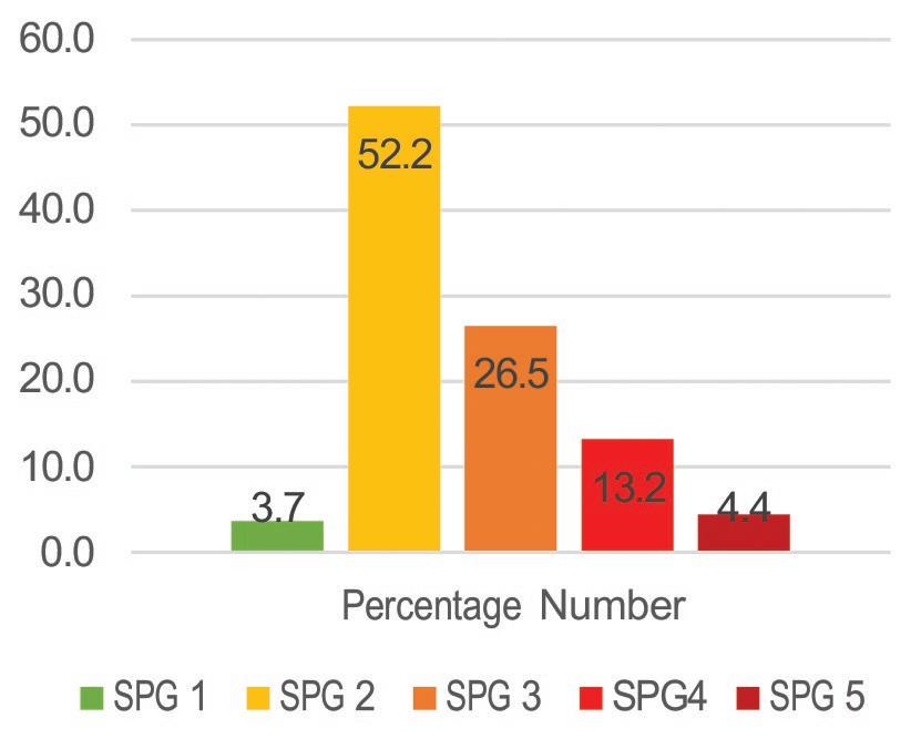
Figure 8: SPG Values by Percentage Number
Therefore, the only treatment work streams considered are detailed in Table 3.
Underdrain repair lengths derived from the inspection program are relatively short, localized repairs; ranging from 1.5 to 21 feet (0.46 metres to 6.4 metres) long. 78 repairs were required for the underdrain pipe system for 56 unique segments.
The overall length of the repairs is only 433 feet (132 metres) of the 58,845 feet (17,936 metres) of inspected length or 0.74% of the system. While the vast majority of the underdrain pipe is in very good condition, it is important to note that isolated collapses or blockages has impacted the function of the system for large areas of the system due to the flat grade and the limited number of outlets in some sections.
For their associated manholes, all defects represent a threat of soil migration or failure risk in close proximity to the Aqueduct and none of the defects have any positive impact on overall groundwater levels.
Therefore, all defects were rationalized for treatment in the usual manner where the quantities are noted in Table 4.
CONCLUSIONS
The primary objective of the Underdrain pipe is to act as a French drain having no gaskets and open joints to lower groundwater levels around the pipe and associated Aqueduct and lower the risk of sulphate related degradation given the local soils in Winnipeg have elevated sulphate levels. In this regard, the pipe has been remarkably effective at protecting another vulnerable concrete structure in a very aggressive soil environment.
A robust Program Development phase enabled and set in place logistical arrangements for a contractor to access the smaller than standard manholes utilizing off-road equipment and the GWWD Railway for cleaning support. This work effort resulted in a 96.5% inspection success rate where only sixteen segments were not fully
BACK TO CONTENTS 24 | NASTT-NW JOURNAL | Spring/Summer 2024
Manhole Rehabilitation Treatment Type Quantity Stabilization (Person Entry) 26 Renovation 20 Replace Manhole Frame 2 Replace Cover 3 Repair / Replace Benching 2 Grout MH/Pipe Interface 9 Remove top of pipe for access 1 Grand Total 63
Table 4: Manhole Rehabilitation Treatment Assignment
Work Type Total Distance / Segment # and Repair # Feet Seg # Repair # Stabilization (Person Entry) 38 20 21 Trenchless Point Repair 105 10 23 External Point Repair 290 26 34 Total 433 56 78
Table 3: Underdrain Pipe Treatment Assignment
THE CHALLENGE TO INSPECT A VINTAGE AQUEDUCT’S UNDERDRAIN PIPE SYSTEM FOR CONDITION ASSESSMENT IN WINNIPEG, MB CANADA
inspected due to their condition and water levels. Conditions of the underdrain, though exhibiting high SPG values, the approach was taken to evaluate certain defects as modes of infiltration and, as long as no loss of ground support was evident, were retained with no assigned rehabilitation. Their resultant SPG value would trigger a higher frequency of re-inspection.
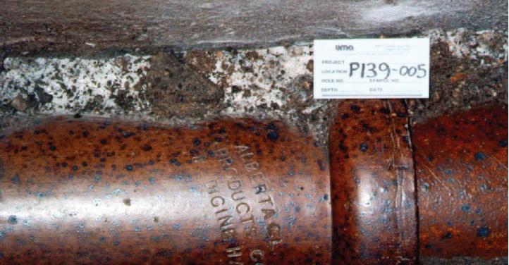
While the number of defects present seem relatively high, their spatial extent is relatively small and the overall condition of the fabric of the pipe is excellent (see Figure 9). Regular assessment and strategic repairs will allow this 100-year-old-plus asset to continue to function for many years.
REFERENCES
i National Association of Sewer Service Companies. (2021). Pipeline Assessment Certification Program Manual, Version 7.0.4
ii Water Research centre plc. (2023). Sewerage Risk Management (former Sewerage Rehabilitation Manual). http://srm.wrcplc.co.uk
“ THE PIPE HAS BEEN REMARKABLY EFFECTIVE AT

BACK TO CONTENTS NASTT-NW.COM | 25
PROTECTING ANOTHER VULNERABLE CONCRETE STRUCTURE IN A VERY AGGRESSIVE SOIL ENVIRONMENT.
Figure 9: Branch I Aqueduct Underdrain Pipe – Present Day Condition, installed 1918

NASTT-NW CHAPTER BUYERS’ GUIDE
When making purchasing decisions about products and services in the trenchless technology industry throughout Manitoba, Saskatchewan, Alberta, and beyond, please support the companies whose advertising makes the NW Trenchless Journal possible. You will find them quickly with our convenient, easy-to-use Buyers’ Guide.
On the following pages, you will find information that will help you meet your purchasing requirements throughout the year ahead. The initial section of this Guide lists categories of products and services along with the various companies that can provide them to you. The following section provides an alphabetical listing of those companies, as well as the contact information you will need to reach them.

2024
BACK TO CONTENTS 26 | NASTT-NW JOURNAL | Spring/Summer 2024
LISTINGS BY CATEGORY
AUGUR BORING
Barbco, Inc.
Herrenknecht Tunneling Systems Canada, Inc.
Michels Canada
ASSET MANAGEMENT
Associated Engineering
CIPP TUBE
Insituform Technologies Limited
CONCRETE LEVELLING
MuddRuckers, Inc.
CONDITION ASSESSMENT
Associated Engineering
IVIS, Inc.
CONSTRUCTION MANAGEMENT
Associated Engineering
CONVEYOR EQUIPMENT
Herrenknecht Tunneling Systems Canada, Inc.
COST ESTIMATION
MAPEI Canada
CUTTERS
Herrenknecht Tunneling Systems Canada, Inc.
DATA COLLECTION SYSTEMS
Associated Engineering
DEWATERING
Michels Canada
DIRECTIONAL DRILLING, RIGS, FLUIDS & ACCESSORIES
Barbco, Inc.
Herrenknecht Tunneling Systems Canada, Inc.
IPEX, Inc.
LaValley Industries
MAPEI Canada
Michels Canada
Precise Crossings
DRILL PIPE
MAPEI Canada
DRILLING CONSUMABLES
MAPEI Canada
EDUCATION/RESEARCH
Barbco, Inc.
ENGINEERING DESIGN
Associated Engineering
Barbco, Inc.
MAPEI Canada
ENVIRONMENTAL PRODUCTS
Barbco, Inc.
MAPEI Canada
EPOXY
MAPEI Canada
Michels Canada
TCI Technologies, Inc.
FLOW MONITORING
IVIS, Inc.
GENERAL CONSULTING
Associated Engineering IVIS, Inc.
GROUTING
MAPEI Canada
Michels Canada
HORIZONTAL DIRECTIONAL BORING
Barbco, Inc.
Brandt Tractor
Herrenknecht Tunneling Systems Canada, Inc.
Michels Canada
HYDRO-EXCAVATORS
Brandt Tractor
IVIS, Inc.
Uni-Jet Industrial Pipe Services
JETTERS
IVIS, Inc.
LATERAL REHAB
IPEX, Inc.
IVIS, Inc.
MANHOLE REHAB
Insituform Technologies Limited
IPEX, Inc.
IVIS, Inc.
MAPEI Canada
Michels Canada
TCI Technologies, Inc.
MICROTUNNELING, SYSTEMS & EQUIPMENT
Herrenknecht Tunneling Systems Canada, Inc.
MAPEI Canada
Michels Canada
MUD SYSTEMS
MAPEI Canada
MuddRuckers, Inc.
PILOT TUBE/GUIDED
BORING EQUIPMENT
Barbco, Inc.
PIPE BURSTING/SPLITTING
IVIS, Inc.
Michels Canada
PIPE CLEANING
Uni-Jet Industrial Pipe Services
PIPE FITTINGS
IPEX, Inc.
PIPE FUSION
Michels Canada
PIPE HANDLING EQUIPMENT
LaValley Industries
PIPE INSPECTION
IVIS, Inc.
PIPE JACKING
Herrenknecht Tunneling Systems Canada, Inc.
Michels Canada
PIPE – PVC
IPEX, Inc.
PIPE RELINING
IPEX, Inc.
IVIS, Inc.
TCI Technologies, Inc.

PIPE RAMMING
Michels Canada
PIPE RELINING
Michels Canada
PIPELINE INSPECTION & EVALUATION
Associated Engineering
IVIS, Inc.
Michels Canada
ROCK DRILLING
Barbco, Inc.
MAPEI Canada
Michels Canada
SEWER- PRESSURE/VACUUM
Insituform Technologies Limited
IVIS, Inc.
Uni-Jet Industrial Pipe Services
BACK TO CONTENTS NASTT-NW.COM | 27
SEWER ROBOTICS
IVIS, Inc.
SLIPLINING
MAPEI Canada
SOIL STABILIZATION
MAPEI Canada
MuddRuckers, Inc.
SPECIALTY TOOLING
Barbco, Inc.
SPOT REPAIR/POINT REPAIR
IVIS, Inc.
MAPEI Canada
TCI Technologies, Inc.
TECHNICAL EDUCATION
Barbco, Inc.
TRENCHING
Brandt Tractor
TUNNEL BORING MACHINES
Barbco, Inc.
Herrenknecht Tunneling Systems Canada, Inc.
MAPEI Canada
TUNNEL-LARGE DIAMETER
Herrenknecht Tunneling Systems Canada, Inc.
MAPEI Canada
TUNNELING PRODUCTS
Herrenknecht Tunneling Systems Canada, Inc.
MAPEI Canada
LISTINGS BY COMPANY NAME
ASSOCIATED ENGINEERING
Jason Lueke
780-451-7666 luekej@ae.com www.ae.com

BARBCO, INC.
Jessica Liston
330-488-9400
jessie@barbco.com www.barbco.com

BRANDT TRACTOR
888-227-2638
sales@brandt.ca www.brandt.ca
HERRENKNECHT TUNNELING SYSTEMS CANADA, INC.
Steffen Dubé
253-447-2300
dube.steffen@herrenknecht.com

INSITUFORM TECHNOLOGIES LIMITED
Andrew Foster
888-982-4717 afoster@aegion.com www.insituform.com
IPEX, INC.
Vadym Hordov
VACUUM EXCAVATING & EXCAVATORS
Brandt Tractor
IVIS, Inc.
VIDEO INSPECTION
IVIS, Inc.
Uni-Jet Industrial Pipe Services
USED/RENTAL EQUIPMENT
Barbco, Inc.
Herrenknecht Tunneling Systems Canada, Inc.
UTILITY LOCATING
Brandt Tractor
IVIS, Inc.
PIERCING RODS & PUSHERS
Brandt Tractor

IVIS, INC.
Dolores Eaton
780-476-2626 marketing@ivisinc.com www.ivisinc.com

LAVALLEY INDUSTRIES
Craig Larson
218-444-3030
craig@lavalleyindustries.com www.lavalleyindustries.com
MAPEI CANADA
1-800-426-2734 customerservicecan@mapei.com

BACK TO CONTENTS 28 | NASTT-NW JOURNAL | Spring/Summer 2024

MICHELS CANADA
Mike Ireland
780-955-2120
mikeireland@michelscanada.com www.michelscanada.com


PRECISE CROSSINGS
Craig Nernberg
780-962-6882
craig@precisecrossings.com www.precisecrossings.ca

Scott Culum
204-633-4879 www.unijet.ca

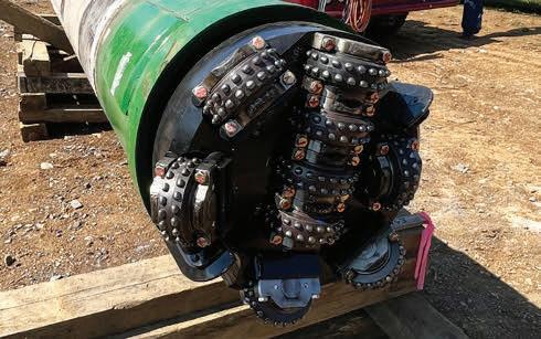
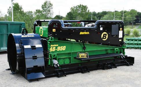


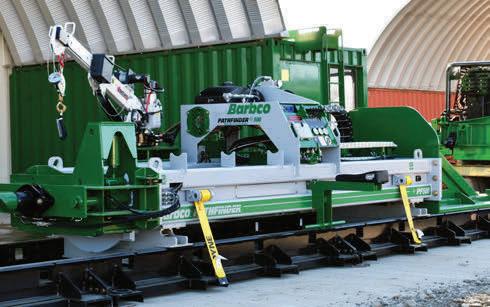
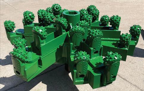

UNI-JET INDUSTRIAL
PIPE LTD.
BACK TO CONTENTS NASTT-NW.COM | 29 ROLLER CONE & DISC CUTTING HEADS AUGER BORING MACHINES & ACCESSORIES GUIDED BORING MACHINES & TRIBOR MACHINES HORIZONTAL DIRECTIONAL DRILLING 1.844.333.2754 trs.rent 117 Pekin Drive SE, East Canton, Ohio 44730 1.817.858.0975 usshoringandequipment.com 11070 S Pipeline Rd, Euless, Texas 76040

ADVERTISER PRODUCT & SERVICE CENTRE
BACK TO CONTENTS
is
We thank them
their support
NASTT-NW
publication
encourage you
contact them
making your purchasing decisions. To make it easier to contact
we have
their advertisement,
number,
COMPANY NAME PAGE PHONE WEBSITE/EMAIL Associated Engineering 6 780-451-7666 www.ae.ca Barbco, Inc. 29 330-488-9400 www.barbco.com Brandt Tractor Ltd. 31 888-2BRANDT www.brandttractor.com Herrenknecht Tunnelling Systems Canada, Inc. 17 253-447-2300 www.herrenknecht.com Insituform Technologies 2 800-234-2992 www.insituform.com IPEX Management, Inc. 3 866-473-9462 www.ipexna.com IVIS, Inc. 7 780-476-2626 www.ivisinc.com LaValley Industries 18 218-444-3030 www.lavalleyindustries.com MAPEI Canada 8 800-426-2734 www.mapei.ca Michels Canada 32 780-955-2120 www.michelscanada.com MuddRuckers, Inc. 18 204-992-6833 www.muddruckers.ca Precise Crossings Ltd. 6 866-962-6882 www.precisecrossings.ca TCI Carbon Fibre Technologies 18 416-409-2211 www.tcicarbonfibre.com Uni-Jet Industrial Pipe Services 17 204-633-4879 www.uni-jetindustrialpipe.ca VIEW US ONLINE NASTT-NW.COM Chad Morrison • 1-866-985-9788 • chad@kelman.ca To reach the targeted readership of the NASTT-NW Journal please contact Chad: 30 | NASTT-NW JOURNAL | Spring/Summer 2024
The NW Trenchless Journal
made possible by the companies below who convey their important messages on our pages.
for
of
and its
and
to
when
these companies,
included the page number of
their phone
and, where applicable, their website.

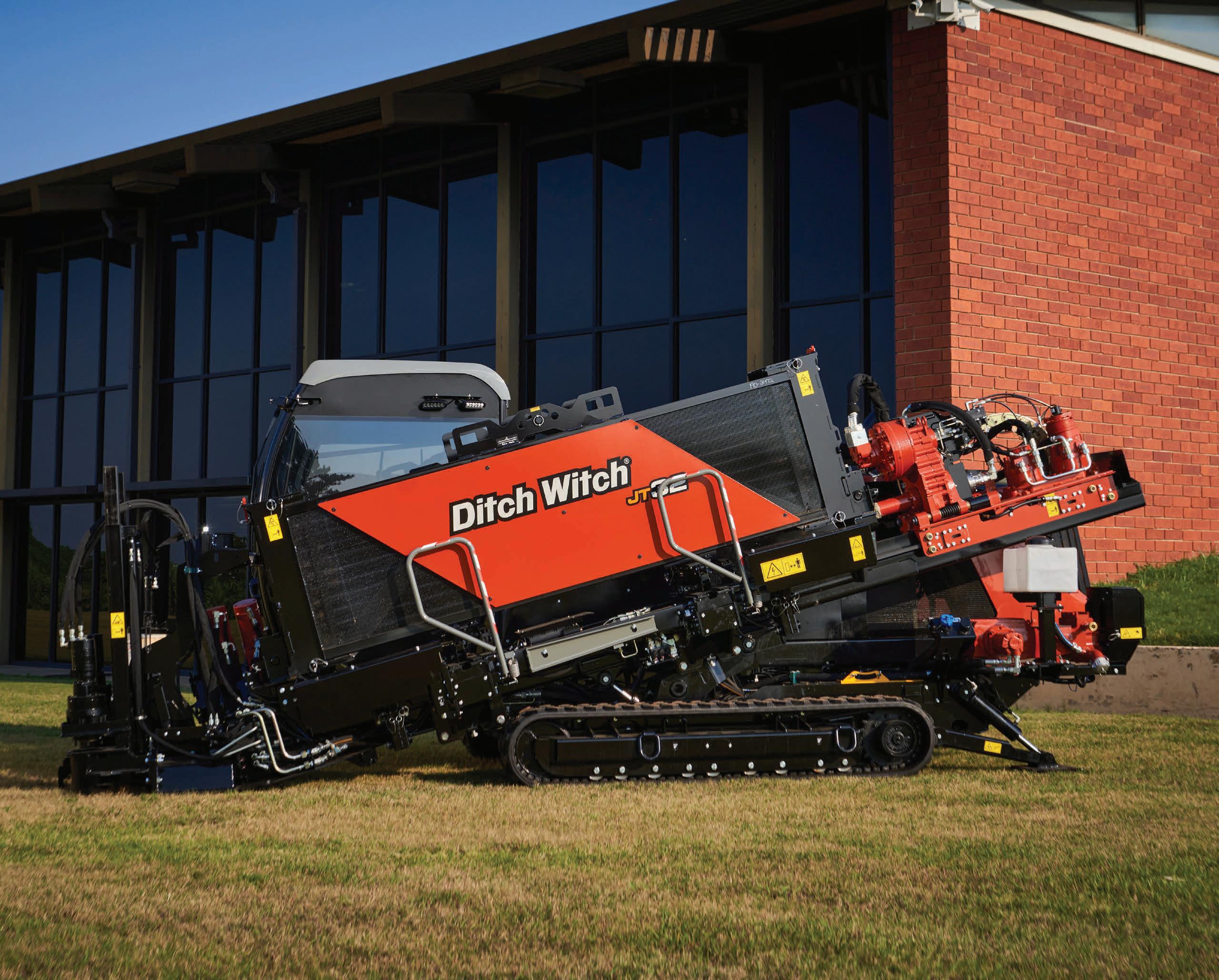
More Support
Better Availability
With
Easier To Own
Brandt
brandt.ca 1-888-227-2638
provides 24/7/365 customer support to keep your operation productive and profitable no matter what comes your way.
Brandt
more in-stock inventory available, Brandt ensures you have access to the machines you need exactly when you need them.
makes ownership easy with flexible in-house financing options to suit the needs of your business. Ditch Witch directional drills pack performance and unrivalled power into a tough line-up of exceptional, easy to own machines. HERE’S THE DRILL.
Expect More.
We are up for any challenge. Complex projects are opportunities to demonstrate our unmatched skill, outside-the-box innovations, and unyielding strength. Whether you are looking for a trenchless solution to minimize surface disruptions or need a consultation on the best tunnelling method approach to add value to your designs, we will exceed your expectations for quality, safety and sustainability.
Partner with Michels Canada and expect more.
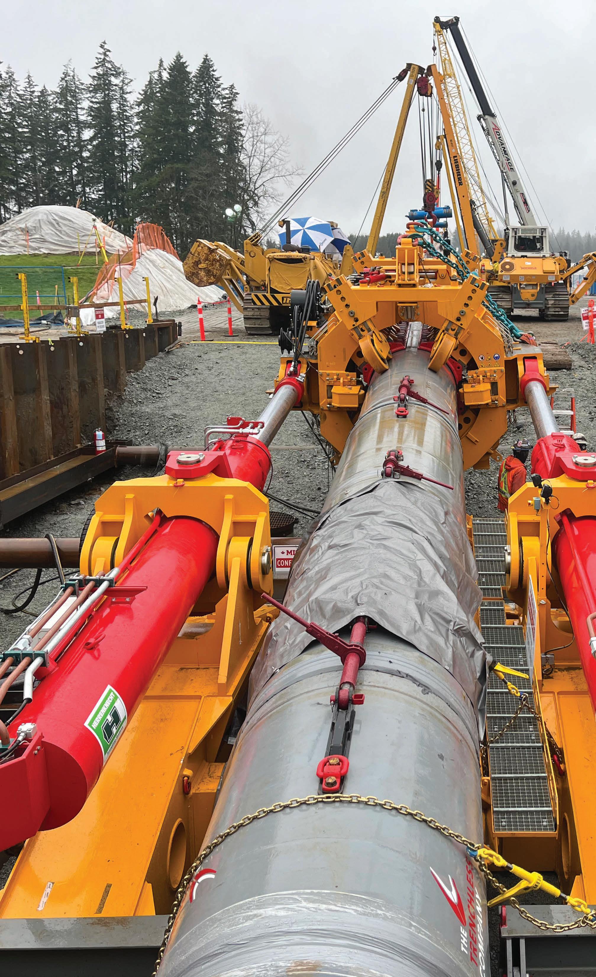
Energy • Infrastructure • Power Construction Solutions For Canada’s Future
