International Journal of Advanced Engineering Research and Science

(IJAERS)
Peer-Reviewed Journal
ISSN: 2349-6495(P) | 2456-1908(O)
Vol-10, Issue-5; May, 2023
Journal Home Page Available: https://ijaers.com/
Article DOI: https://dx.doi.org/10.22161/ijaers.105.3
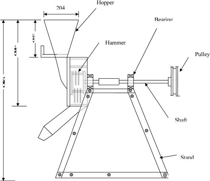
Half Sieve Hammer Mill Machine
Dhanashri Uday Bulbule, Ramdas Vithoba Kumbhar, Avinash Arun Hovale, Sawant
Shrayes Shailendra
Department of Mechanical Engineering, Sanjay Bhokare Group of Institute, Miraj, Maharashtra
Received: 25 Mar 2023,
Receive in revised form: 22 Apr 2023,
Accepted: 01 May 2023,
Available online: 09 May 2023
©2023 The Author(s). Published by AI Publication. This is an open access article under the CC BY license (https://creativecommons.org/licenses/by/4.0/).
Keywords Design, small hammer mill, materials particles, fineness, shaft speed
Abstract The two types of Hammer Mills Full sieve / full screen Hammer Mill (Grinder) & Half Sieve Hammer mills used for crushing purpose. These Hammer Mills widely used in Feed Sector, Organic Fertilizer Sector for crushing the raw material to desired size even these are used in Bio mass, food industries, pharmaceutical etc. A hammer mill is a machine or mill whose purpose is to shred or crush aggregate material into smaller pieces by the repeated blows of little hammers or beaters. A number of ingredients used in making feed for Poultry and other livestock are granular in nature and need to be broken down for further processing. Our Hammer mills have adopted technology over time to grind these raw materials. our machines have numerous industrial applications in Poultry Feed, Animal & Cattle Feed, Fish feed and, Organic Fertilizer sectors, for crushing the raw material to desired size even these are used in Bio mass, food industries, pharmaceutical etc. This machine is used for reducing the particle size of different ingredients in feed. It consists of a rotor on which swinging hammers are mounted in different patterns, which when rotate at high speed, strike with incoming feed ingredients and break these.
I. INTRODUCTION
Nowadays, the development of animal and poultry production needs to exert more efforts to increase and maintain high levels of feeding crop, in addition to improve the quality and quantity by decreasing grain losses during pre- processing operation, selecting the proper diet in the acceptable phase of livestock and reducing the consumed energy. The hammer mill is used almost exclusively in preparation of broiler rations because of its simplicity, ease to operate and low maintenance cost so, it had been widely spread in most of the poultry.
Until two centuries ago, not much attention was paid to animal nutrition. Mon gastric animals were left to search their own feed, or they were fed often from byproducts of food production and household wastes. With mechanization of agriculture and increase of production efficiency during the 19th century, cultivation and use of agricultural products for animal feed became increasingly common. In the first half of the XX century, farm animals
were fed with high quantities of grains, with small amounts of protein. Over time, research in animal nutrition progressed facilitated more precise definition of the composition of the feed. Mixing the ingredients to tentatively satisfy nutrient requirements became common (Ewing, 1951). Modern era of poultry farming is characterized by well-organized production. Under these conditions, nutrition has a crucial influence on the utilization of feed and the quality of the animal products (meat, eggs). Thus, nutrition is also pivotal for the economy of production. New breeds of domestic animals with higher productivity also demand proper and controlled diets to allow them to express their genetic potential. These changes in poultry production have set new requirements in terms of preparing feed for the animals. These improvements have resulted in feed production gradually moving towards fully satisfying the nutritional needs of animals, at least cost
II. EQUATIONS
Theoretical design consideration:-
The design was carried out to occur the safety basics for the operator. The deflection of the hammers while in operation was considered in the design. Swinging instead of stiff hammers was used to avoid rotor and hammers from getting stocked in case a hammer comes in contact with a material hard to break at the first impact. Design theories and calculations determination of shaft speed:-
The shaft speed was calculated by using the following formula:-
��1/D2 = ��2/N1
Where:
��1 = Diameter of drive pulley, mm;
��2 = Diameter of driven pulley, mm;
��1 = Revolution of the drive pulley, rpm;
��2 = Revolution of the driven pulley, rpm.
The nominal length of the belt was calculated by using the following formula:-
�� = 2�� + ��/2 (��1 +D2) + ((��1−��2/4C) ^2
Where:
L = Length of the belt, mm;
C = Centre distance between driven pulley and the drive one, mm.
Centre distance minimum, ����i�� was calculated using the following formula:-
����i�� = 0.55 (��1 + ��2) + ��
The maximum center distance was calculated using the Patton:-
�������� = 0.55 (��1 + ��2) + ��
Where:
T =Nominal belt thickness;
��1 =Driven pulley diameter;
��2 = Drive pulley diameter.
The belt contact angle (��) is given by equation, Hall et al., 1980
��i�� 1�� = (�� ��/c)
Where:
R = Radius of the driven pulley, mm;
r = Radius of the drive pulley, mm.
The angles of wrap (a1anda2) for drive and driven pulleys were given by:-
��2 = 180 − ��i�� 1 (�� ��/c)
Where:
��1 = Angle of wrap for the drive pulley;
��2 = Angle of wrap for the driven pulley.
The driven belt tension determined using the following formula: -
��2= (��1−����2) /������ [ ���� / ��i��1/2��]
��1 = S.A
S = the maximum permissible belt stress, N/��2;
A = Area of belt, ��2;
M =Mass per unit length of belt, N. ��;
�� = Coefficient of friction between the belt and the pulley surface,
��= Arc of contact of the belt on the pulley, Rad;
�� ��2= Centrifugal force acting on the belt, N.
The torque and power transmitted for the shaft were determined using the following formula:-
The torque available at the driven pulley can be expressed as: -
���� = (��2 - ��1) R
Where:
���� = Resultant torque, Nm;
��1 & ��2 = Tension in the belt, N;
R = Radius of driven pulley, mm.
The available power can be expressed as:-
P = ����. R ���� = (T2 - T1) R ����
Where:
P = Power transmitted, Watts;
���� = Angular velocity, rad/s.
Hammer weight determined using t formula:-
Wℎ = ���� × ��
Where:
���� = Mass of the hammer, kg;
g = Acceleration due gravity =9.81.
The fabricated material was mild steel, density of 7.85g/����3
The centrifugal force exerted by the hammer using the formula:-
�� = ����√���� = ����/r
Where:
ω = Rotational speed of the rotor, radians/seconds;
��1 = 180 − ��i�� 1 (�� ��/c)
m = Mass of the ore, kg;
r = Radius of the rotor, m;
s = the ore stiffness to breakage, N/m.
ω =2������/60
Where:
�� = Number of revelations
Hammer shaft diameter was calculated using the formula:-
����������= ��2��/8
Where:
���������� = Maximum bending moment, N.m;
��=Shaft length, mm;
W = Force per unit length, N/m
�� (������������������) = ������������/I
��/( ��������. ) =Z=���� = ����/Z
Where:
�������� = Distance from neutral axis to outer, m;
�� = Moment of inertia, ��4;
Z =Section modulus, ��3. For round bar:-
�� = ����4/64
�� = ����3/32
Twisting of the rotational shaft is neglected from the torsion rigidly calculation.
The rotational shaft diameter was calculated using the following formula: - The ASME code equation for solid shaft having little or no axial loading is
��3 = 16/������ √(��������)2 + (��������)2
Where:
d = Shaft diameter;
s =Shear stress from tables for shafts with keyway;
Kb = Combined shock and (0) fatigue factor applied to bending moment;
Kt = Combined shock and fatigue factor applied to torsional moment;
Mt =Torsional moment, N.m;
Mb =Bending moment, N.m.
Hammer mill calculated parameters:The designed hammer mill calculated parameters tabulated in Table (1).
III. FIGURES AND TABLES
IV. CONCLUSION
The purposes and intentions for which this research was set to achieve have been achieved. The hammer machine with easily detachable incorporated sieve was designed and fabricated from martensitic stainless steel. Idle and load tests were carried out and found to be capable of pulverizing to milling efficiency of 89% to 99%, which shows that the performance of the machine compares favorably with the performances of the other mills developed. The machine can be powered by either electric motor or fuel powered engines of the same capacity to achieve the same efficiency and effectiveness. Observation deduced from the tested results showed that the performance of the newly developed machine is better than the exciting versions
a. Advantages
• It is a cost-effective machine with low energy requirement for operation, which saves costs.
• It can grind/crush different types of materials at high angular velocity.
• Its reduction ratio and capacity are high, irrespective of whether it is used for primary, secondary, or tertiary grinding.
• Size reduction of material happens dynamically. It is especially great for brittle material.
• The installation of the machine is simple & easy, and it offers continuous operation.
• The specified top size is produced without the need for a closed-circuit crushing system.
• It occupies a small space and is easy to clean and maintain.
b. Applications
1) Used in cattle feed industries.
2) Used in pharmaceutical company.
3) Used in home applications
ACKNOWLEDGEMENTS
Gratitude is hardest emotion to express and often one doesn’t find adequate words to covey all the one feels.
We take this opportunity to thank our beloved Director of our Institute.
We are indeed grateful to the Head of Mechanical Engineering Department, Mrs. D. U. Bulbule for giving us helpful advice and for providing all necessary facilities to conduct our project work.
A sense of prevailing satisfaction and achievement envelops the whole feeling of having completed under the guidance of Mrs. D. U. Bulbule. We wish to express our respect, deep sense of gratitude to him for her valuable guidance, keep interest and co-operation without which it would have been impossible to accomplish this project work successfully. It was indeed great experience to work under his guidance.
In the last we would like to thank the management of ATS, Sanjay Bhokare Group of Institutes, Miraj for providing us such an opportunity to learn from these experiences. We are also thankful to our whole group members and most of all to our parents who have inspired us to face all the challenges and win all the hurdles in life. Thank you All.
REFERENCES
[1] Adekomaya, S. O., and O. O. Samuel. 2014. “Design and Development of a Petrol-Powered Hammer Mill for Rural Nigerian Farmers.” Journal of Energy Technologies and Policy 4 (4): 65–72
[2] Ajaka, E. O., and A. Adesina. 2014. “‘Design, Fabrication, and Testing of a Laboratory Size Hammer Mill’. Department of Mining Engineering. The Federal University of Technology, Akure, Nigeria.” International Journal of Engineering and Advanced Technology Studies 2 (2): 11–21. Donnel, H. 1983. Farm Power and Machinery. New Delhi, India:
[3] McGraw Hill. El Shal, M. S., M. A. Tanfik, A. M. El Shal, and K. A. Metwally. 2010. “Study the Effect of Some Operational Factors on Hammer Mill.” Journal of Farm Machinery and power 27: 54–74
[4] Milling efficiency against time. Figure 15: Picture of the machine during fabrication. Ariel view of the completed hammer mill machine. African Journal of Science, Technology, Innovation and Development