Operating and maintenance instructions
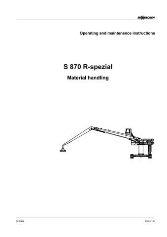
S 870 R-spezial Material handling
1m
8.5t
06.2004
870.5.131
Foreword
Target group
Notes on the manual
These instructions are to familiarize the operator of a Sennebogen material handling device with the initial operation, operation, maintenance and transportation of the equipment. Detailed information on the required prior knowledge and qualifications of the operator can be found in Chapter 1 SAFETY of these instructions.
Read the manual, in particular Chapter 1 SAFETY thoroughly, before starting work with the machine. Keep manual in a safe place for future use. WARNING! Only work with the machine once these manual have been read and completely understood. Observe safe working load tables in Section 3.2. Forbid unsafe operation or unsafe maintenance. Setting up, operation and maintenance of the machine is only permitted by trained personnel. The employer is responsible for the qualification and training of the personnel. These manual must always be available in the driver's cab.
For reasons of clarity, the specified safety devices are not shown in some of the illustrations. Operation with safety devices removed is not permitted! DANGER Safety devices must be fitted when working with the machine.
Current when going to press
Copyright
Ongoing development ensures the advanced technology and the high level of quality in our machines. This may result in deviations between these manual and your machine. Errors can also not be ruled out. Please understand, that no legal claims can be derived from the specifications, illustrations and descriptions within these instructions.
© Straubing 2004, Sennebogen Maschinenfabrik GmbH Reproduction, also in part, only with written permission of Sennebogen Maschinenfabrik GmbH, Straubing, Germany. Printed in Germany.
Table of contents
S 870 R-spezial / 06.2004
1
Safety . . . . . . . . . . . . . . . . . . . . . . . . . . . . . . . . . . . . . . 1-1 1.1 General . . . . . . . . . . . . . . . . . . . . . . . . . . . . . . . . . 1-1 1.2 Correct use . . . . . . . . . . . . . . . . . . . . . . . . . . . . . . 1-3 1.3 Misuse . . . . . . . . . . . . . . . . . . . . . . . . . . . . . . . . . . 1-3 1.4 Safety notes . . . . . . . . . . . . . . . . . . . . . . . . . . . . . 1-4 1.4.1 General . . . . . . . . . . . . . . . . . . . . . . . . . . . . 1-4 1.4.2 Transportation . . . . . . . . . . . . . . . . . . . . . . . 1-8 1.4.3 Starting operation . . . . . . . . . . . . . . . . . . . . 1-9 1.4.4 Operation . . . . . . . . . . . . . . . . . . . . . . . . . 1-10 1.4.5 Maintenance . . . . . . . . . . . . . . . . . . . . . . . 1-11 1.5 Responsibilities of the employer . . . . . . . . . . . . . 1-12 1.6 Safety devices . . . . . . . . . . . . . . . . . . . . . . . . . . . 1-16 1.7 Warning and notice signs on the machine . . . . . 1-17 1.8 Disposal . . . . . . . . . . . . . . . . . . . . . . . . . . . . . . . . 1-20 1.9 Hand signals . . . . . . . . . . . . . . . . . . . . . . . . . . . . 1-20
2
Overview . . . . . . . . . . . . . . . . . . . . . . . . . . . . . . . . . . . . 2-1 2.1 Complete machine . . . . . . . . . . . . . . . . . . . . . . . . 2-1 2.2 Undercarriage . . . . . . . . . . . . . . . . . . . . . . . . . . . . 2-2 2.3 Upper structure . . . . . . . . . . . . . . . . . . . . . . . . . . . 2-3 2.4 Driver's cab . . . . . . . . . . . . . . . . . . . . . . . . . . . . . . 2-6
3
Technical data . . . . . . . . . . . . . . . . . . . . . . . . . . . . . . . 3-1 3.1 Base machine . . . . . . . . . . . . . . . . . . . . . . . . . . . . 3-1 3.2 Safe working loads . . . . . . . . . . . . . . . . . . . . . . . . 3-3 3.3 Appendix . . . . . . . . . . . . . . . . . . . . . . . . . . . . . . . . 3-5
4
Starting operation . . . . . . . . . . . . . . . . . . . . . . . . . . . . 4-1 4.1 Safety notes . . . . . . . . . . . . . . . . . . . . . . . . . . . . . 4-1 4.2 Initial operation . . . . . . . . . . . . . . . . . . . . . . . . . . . 4-2 4.3 Checks before starting operation . . . . . . . . . . . . . 4-2 4.4 Switching on machine . . . . . . . . . . . . . . . . . . . . . . 4-4 4.4.1 Restraint belt . . . . . . . . . . . . . . . . . . . . . . . . 4-4 4.4.2 Starting engine . . . . . . . . . . . . . . . . . . . . . . 4-5 4.4.3 Shut down engine . . . . . . . . . . . . . . . . . . . . 4-5 4.4.4 External starting . . . . . . . . . . . . . . . . . . . . . 4-6 4.4.5 Bring machine up to operating temperature 4-7
0-1
Table of contents
0-2
5
Operation . . . . . . . . . . . . . . . . . . . . . . . . . . . . . . . . . . . 5-1 5.1 Safety notes . . . . . . . . . . . . . . . . . . . . . . . . . . . . . . 5-1 5.2 Driver's cab . . . . . . . . . . . . . . . . . . . . . . . . . . . . . . 5-2 5.2.1 Shifting the driver's cab hydraulically . . . . . 5-4 5.2.2 Emergency Lowering . . . . . . . . . . . . . . . . . . 5-7 5.3 Operating elements . . . . . . . . . . . . . . . . . . . . . . . 5-10 5.3.1 Overview . . . . . . . . . . . . . . . . . . . . . . . . . . 5-10 5.3.2 Control panel, left . . . . . . . . . . . . . . . . . . . 5-11 5.3.3 Control lever, left . . . . . . . . . . . . . . . . . . . 5-13 5.3.4 Control lever, right . . . . . . . . . . . . . . . . . . . 5-14 5.3.5 Safety lever . . . . . . . . . . . . . . . . . . . . . . . . 5-15 5.3.6 Sennebogen Diagnosis System (SDS) . . . 5-16 5.3.7 Control panel, right hand, back . . . . . . . . . 5-24 5.3.8 Control panel, front right . . . . . . . . . . . . . . 5-25 5.3.9 Central lubrication system (optional) . . . . . 5-28 5.3.10Slewing ring lubrication (option) . . . . . . . . 5-29 5.4 Heating . . . . . . . . . . . . . . . . . . . . . . . . . . . . . . . . 5-31 5.5 Special equipment . . . . . . . . . . . . . . . . . . . . . . . . 5-32 5.5.1 Air conditioner (optional) . . . . . . . . . . . . . . 5-32 5.5.2 Auxilary heating system . . . . . . . . . . . . . . 5-33 5.6 Starting work . . . . . . . . . . . . . . . . . . . . . . . . . . . . 5-34 5.6.1 Safety notes . . . . . . . . . . . . . . . . . . . . . . . 5-34 5.6.2 Driving machine . . . . . . . . . . . . . . . . . . . . . 5-35 5.6.3 Slewing upperstructure . . . . . . . . . . . . . . . 5-39 5.6.4 Limit shutdown - compact boom . . . . . . . . 5-42 5.6.5 Limit shutdown - grabbing jib . . . . . . . . . . . 5-44 5.6.6 Bypassing the ”Jib retract” safety limit shutdown . . . . . . . . . . . . . . . . . . . . . . . . . . 5-47 5.6.7 Hoisting/lowering loads . . . . . . . . . . . . . . . 5-48 5.6.8 Grab operation . . . . . . . . . . . . . . . . . . . . . 5-50 5.6.9 Refueling machine . . . . . . . . . . . . . . . . . . . 5-51
6
Maintenance . . . . . . . . . . . . . . . . . . . . . . . . . . . . . . . . . 6-1 6.1 Safety notes . . . . . . . . . . . . . . . . . . . . . . . . . . . . . . 6-1 6.2 General notes . . . . . . . . . . . . . . . . . . . . . . . . . . . . 6-2 6.2.1 Cleaning work . . . . . . . . . . . . . . . . . . . . . . . 6-2 6.2.2 Oils and lubricants . . . . . . . . . . . . . . . . . . . . 6-3 6.2.3 Welding work . . . . . . . . . . . . . . . . . . . . . . . . 6-4 6.3 Driving engine . . . . . . . . . . . . . . . . . . . . . . . . . . . . 6-5 6.3.1 Engine oil . . . . . . . . . . . . . . . . . . . . . . . . . . . 6-6 6.3.2 Air filter . . . . . . . . . . . . . . . . . . . . . . . . . . . . 6-8
S 870 R-spezial / 06.2004
Table of contents
6.4
6.5
6.6
6.7 6.8
7
S 870 R-spezial / 06.2004
6.3.3 Cooler . . . . . . . . . . . . . . . . . . . . . . . . . . . . 6-10 6.3.4 Belt drives . . . . . . . . . . . . . . . . . . . . . . . . . 6-11 Hydraulic system . . . . . . . . . . . . . . . . . . . . . . . . . 6-12 6.4.1 Hydraulic hose lines . . . . . . . . . . . . . . . . . 6-14 6.4.2 De-pressurizing hydraulic system . . . . . . . 6-15 6.4.3 Checking oil level . . . . . . . . . . . . . . . . . . . 6-16 6.4.4 Changing hydraulic oil . . . . . . . . . . . . . . . . 6-17 6.4.5 Return filter – changing filter element . . . . 6-19 6.4.6 Leak-oil filter – changing filter element . . . 6-20 6.4.7 Changing ventilation filter . . . . . . . . . . . . . 6-21 6.4.8 Micro-filter – changing filter element (optional) . . . . . . . . . . . . . . . . . . . . . . . . . . 6-22 6.4.9 Checking and cleaning hydraulic oil cooler 6-23 6.4.10Checking preload pressure of pressure accumulator . . . . . . . . . . . . . . . . . . . . . . . . 6-24 Running gear . . . . . . . . . . . . . . . . . . . . . . . . . . . . 6-25 6.5.1 Cleaning and Lubricating . . . . . . . . . . . . . 6-25 6.5.2 Travel gear . . . . . . . . . . . . . . . . . . . . . . . . 6-25 6.5.3 Crawler chain . . . . . . . . . . . . . . . . . . . . . . 6-27 6.5.4 Sprocket . . . . . . . . . . . . . . . . . . . . . . . . . . 6-30 6.5.5 Track shoes . . . . . . . . . . . . . . . . . . . . . . . . 6-30 6.5.6 .Slewing ring . . . . . . . . . . . . . . . . . . . . . . . 6-31 6.5.7 Retighten the slewing ring screws . . . . . . . 6-33 Electrical system . . . . . . . . . . . . . . . . . . . . . . . . . 6-35 6.6.1 Batteries . . . . . . . . . . . . . . . . . . . . . . . . . . 6-35 6.6.2 Fuses . . . . . . . . . . . . . . . . . . . . . . . . . . . . 6-36 Heating . . . . . . . . . . . . . . . . . . . . . . . . . . . . . . . . 6-37 Appendix . . . . . . . . . . . . . . . . . . . . . . . . . . . . . . . 6-38 6.8.1 Maintenance schedule . . . . . . . . . . . . . . . 6-38 6.8.2 Schedule of Lubrication Points . . . . . . . . . 6-41 6.8.3 Capacities . . . . . . . . . . . . . . . . . . . . . . . . . 6-42 6.8.4 Tightening torques for bolts . . . . . . . . . . . . 6-43
Setting up . . . . . . . . . . . . . . . . . . . . . . . . . . . . . . . . . . . 7-1 7.1 Assembling the undercarriage . . . . . . . . . . . . . . . . 7-1 7.2 Mounting the pylon . . . . . . . . . . . . . . . . . . . . . . . . 7-5 7.3 Detaching/attaching counterweight . . . . . . . . . . . . 7-6 7.3.1 Detaching counterweight . . . . . . . . . . . . . . . 7-6 7.3.2 Attaching counterweight . . . . . . . . . . . . . . . 7-8
0-3
Table of contents
8
Transportation . . . . . . . . . . . . . . . . . . . . . . . . . . . . . . . 8-1 8.1 Safety notes . . . . . . . . . . . . . . . . . . . . . . . . . . . . . . 8-2 8.2 Dimensions and weights . . . . . . . . . . . . . . . . . . . . 8-3 8.2.1 Transportation dimensions . . . . . . . . . . . . . 8-3 8.2.2 Weights . . . . . . . . . . . . . . . . . . . . . . . . . . . . 8-5 8.3 Lift machine . . . . . . . . . . . . . . . . . . . . . . . . . . . . . . 8-6 8.4 Secure machine . . . . . . . . . . . . . . . . . . . . . . . . . . . 8-7
9
Troubleshooting . . . . . . . . . . . . . . . . . . . . . . . . . . . . . . 9-1 9.1 Driving engine . . . . . . . . . . . . . . . . . . . . . . . . . . . . 9-1 9.2 Hydraulic system . . . . . . . . . . . . . . . . . . . . . . . . . . 9-2 9.3 Heating . . . . . . . . . . . . . . . . . . . . . . . . . . . . . . . . . 9-4 9.4 Air conditioner (optional) . . . . . . . . . . . . . . . . . . . . 9-5 9.5 Running gear . . . . . . . . . . . . . . . . . . . . . . . . . . . . . 9-6 9.6 Cab . . . . . . . . . . . . . . . . . . . . . . . . . . . . . . . . . . . . 9-6
10 Appendix . . . . . . . . . . . . . . . . . . . . . . . . . . . . . . . . . . . 10-1 10.1 List of abbreviations . . . . . . . . . . . . . . . . . . . . . . . 10-1 10.2 Indexes . . . . . . . . . . . . . . . . . . . . . . . . . . . . . . . . 10-2 10.3 Driver's seat . . . . . . . . . . . . . . . . . . . . . . . . . . . . . 10-2 10.4 Cleaning radiator . . . . . . . . . . . . . . . . . . . . . . . . . 10-2 10.5 Central lubrication system . . . . . . . . . . . . . . . . . . 10-2 10.6 Aux. heating system . . . . . . . . . . . . . . . . . . . . . . 10-2 10.7 Warranty manual . . . . . . . . . . . . . . . . . . . . . . . . . 10-2 10.8 Lubricants table . . . . . . . . . . . . . . . . . . . . . . . . . . 10-2
0-4
S 870 R-spezial / 06.2004
Safety - General
1
Safety
1.1 General The machine is built to state of the art standards and according to recognized technical safety regulations. However, danger may still exist during its use to persons, machine and other proper-ty, if the machine is not operated according to regulations the machine is not operated by trained personnel or not maintained the safety notes are not observed.
In additional to the safety notes in these manual, national and international regulations also apply. In the Federal Republic of Germany e.g: Winches, Lifting and pulling devices (VBG 8) Cranes (BGV D6) Hoisting devices in lifting appliance operation (VBG 9a) EC Machinery guideline (89/392/EEC) Safety for machines (DIN EN 292)
Note If the national regulations deviate from our recommendations, then the stricter ru-le applies.
S 870 R-spezial / 06.2004
1-1
Safety - General
Marking of notes
These manual contain safety notes, which highlight dangerous working practices. These safety not-es are marked with a warning symbol and a key-word. This warning symbol means: Attention - this concerns your safety and the safety of others. The associated keyword signifies the degree of danger: DANGER Is used for great, directly threatening danger. If this danger is not averted, serious physical injuries or loss of life of persons will result. WARNING Is used for potentially dangerous situations. If this danger is not averted, serious physical injuries or loss of life of persons may result. CAUTION Is used for potentially dangerous situations. If this danger is not averted, physical injuries or serious material dam-age may result.
Notes which make the work easier or contribute to better under-standing when operating the machine are displayed in the following way: Note Indicates notes which draw attention to peculiarities.
Note Indicates cross references to other documents.
1-2
S 870 R-spezial / 06.2004
Safety - Correct use
1.2
Correct use
The correct use of the machine concerns solely the hoisting, driving and transferring of loads. Permitted work tools are: Grab Magnetic systems. Specifications according to Chapter 3 TECHNICAL DATA. Observe the performance details of the machine. Any other use or use beyond this is classed as not correct.
Work place: The work place of the machine operator is in the driver's cab of the machine.
Target group
The machine has been developed for demanding work. Persons working on or with the machine must be trained or instructed for that purpose. The operation and deployment may only be carried out by persons suitably instructed. Initial operation, maintenance, transportation and assembly/dismantling only by trained specialists.
1.3 Misuse Incorrect use (misuse) applies in particular to: hoisting, driving and transporting of persons tilted pulling of loads dragging of loads pulling free of jammed loads operation of the machine in explosive environment. WARNING Misuse excludes all liability of the manufacturer! The risk is borne solely by the operator.
S 870 R-spezial / 06.2004
1-3
Safety - Safety notes
1.4
Safety notes
The safety notes in these manual are guidelines for the safe use of the machine by qualified machine operators. However, Sennebogen cannot anticipate every situation in practice which may result in danger. Therefore, the safety notes and warnings on the machine and in the manual cannot be all inclusive. The owner and machine operator still remain responsible for safety.
1.4.1 General Danger area
The danger area is the area around the machine where persons can be reached by: operational motions of the machine working equipment and its attachments swinging or falling loads falling working equipment. DANGER No persons must be within the danger area! The machine operator must give warning signals in case of danger to persons. If the persons do not leave the danger area despite warning, work must be stopped. To avoid becoming crushed by solid components, e.g. buil-dings, walls to be removed, scaffolding or other machinery, a sufficient safety distance (min 500 mm) must be maintained. If the safety distance cannot be maintained, then the area between the solid structure and the work area of the machine must be cordoned off. If the machine operator has restricted driving and working vision, then he must be guided.
1-4
S 870 R-spezial / 06.2004
Safety - Safety notes
Personal protective equipment
Stability
The operating personnel are obliged by national regulations to wear the necessary personal protective clothing during work on the machine (e.g. safety helmet, ear protection, protective gloves, safety boots).
Position machine on a firm, even surface. If necessary, stabilize ground. Caution at excavation edge, slopes, dips, etc. Position outriggers also on a firm, even surface. Do not raise machine using the outriggers. The tires must always maintain ground contact. Observe wind speeds! The lowest stability is when the working equipment lies across the direction of travel. The highest stability is when the working equipment lies diagonally (see illustration below).
DANGER Do not carry out any form of work which will affect the stability of the machine! Observe the decreased stability during lateral swinging of load.
S 870 R-spezial / 06.2004
1-5
Safety - Safety notes
Working near power lines
Under supervision, clearly mark the lines in area of building site. Before starting work! Always consider overhead lines to be live. Guide machine so that neither parts of the machine nor suspended loads extend into the danger area. Maintain safety distance to overhead lines. If national regulations recommend no other values, adhere to the following minimum distances: Rated voltage (Volt)
Safety clearance (meter)
to 1000 V
1,00
over 1000 V to 110 kV
3,00
over 110 kV to 220 kV
4,00
over 220 kV to 380 kV
5,00
unknown
5,00
Use a guide to monitor the safety distance. The insulation elements fitted to the machine, protective cages or proximity warning devices do not replace the listed minimum distances. In windy conditions, the overhead lines and the working equipment can swing and consequently decrease the distance.
Electricity transfer
In the case of electricity transfer, the following rules apply: Do not leave the driver's cab. Warn those outside from approaching or touching the machine. If possible, move all working equipment or the entire machine out of the danger area. Arrange switching off of power. Only leave the machine once the touched or damaged line is switched off. DANGER If the machine has to be vacated in the case of an emergency, e.g. danger of fire, do not touch the machine and the ground simultaneously. Jump off the machine with feet together.
1-6
S 870 R-spezial / 06.2004
Safety - Safety notes
Qualification of personnel
The machine must only be operated and maintained by qualified personnel.
Excerpt from VBG 40
The independent operation or maintenance of earth-moving machinery must only be carried out by persons who are 18 years or over, are physically and mentally suitable, are trained in the operation and maintenance of earth-moving equipment and have confirmed their ability to do so to the employer and who can be expected to reliably carry out the appointed work. They must be appointed by the employer for the operation and maintenance of earth-moving equipment.
S 870 R-spezial / 06.2004
1-7
Safety - Safety notes
1.4.2 Transportation WARNING The respective transport operator is always responsible for the transportation of machine and accessories.
Observe valid regulations for securing of loads. When loading and transporting, secure the machine and its working equipment from unintended movement. Clean running and driving gear of machine sufficiently from mud, snow and ice, so that ramps can be accessed without danger of sliding. Provide low loader access ramps with wooden planks before driving crawler vehicles onto them. Check conditions of route before starting journey. Only transport machine on intended securing and lifting points.
1-8
S 870 R-spezial / 06.2004
Safety - Safety notes
1.4.3 Starting operation WARNING Check that all safety devices of the machine are complete and correctly secured. Wear protective work clothing (safety helmet, eye protection), if working conditions necessitate. Take off jewelry or loose clothing. Secure loose items e.g. tools or other accessories. Agree on hand signals with guide. Obtain information on first aid and rescue facilities. Carry out checks before starting operation according to Section 4.3. Enter and exit machine only when stationary. Use the appropriate steps and ladders: – If necessary, clean steps and ladders before use – Do not hold any items when climbing up or down. Lift items of equipment onto machine using a rope or lifting gear. – Do not use operating elements in driver's cab as grips. Ensure that no persons are within the danger area. Check safety devices of machine (brakes, signal and lighting devices). Check for correct function of operating elements and safety devices while driving slowly.
S 870 R-spezial / 06.2004
1-9
Safety - Safety notes
1.4.4 Operation WARNING Observe Chapter 1 SAFETY. Before operating, carry out checks according to Section 4.3. Persons working on or with the machine must be trained or instructed for that purpose. The operation and deployment may only be carried out by persons suitably instructed. Proceed with utmost caution if you override the jib end limit. Ensure that no persons are within the danger area. Maintain safety distance to overhead lines. Only operate the machine from the driver's seat. Do not transport persons with the machine. Consider environment conditions, e.g. poor visibility, wind speeds, etc. Use the safe working load tables specifically for that machine. Observe performance details. Check that anchorage points have a sufficient safe working load. Observe guide signals as necessary. Position jib in direction of travel during long journeys. Before leaving the driver's cab: – Completely lower cab if necessary – Park machine on a firm surface. If necessary, set back from excavation edge – Lower suspended loads – Secure working equipment – Pull safety lever to the rear – Chock wheels/running gear – Switch off engine – Lock driver's cab, secure with warning lights if necessary.
1 - 10
S 870 R-spezial / 06.2004
Safety - Safety notes
1.4.5 Maintenance WARNING The maintenance work described may only be carried out by trained and instructed specialist personnel. Wear personal protection equipment (e.g. safety helmet, ear protection, protective gloves, safety boots) where working conditions require. Observe accident-prevention and safety regulations. Lower suspended loads and jib to the ground. Pull left safety lever to the rear. Shut down machine and secure against unauthorized re-starting before starting with maintenance work. Place warning sign on operating elements. Smoking or handling with open flame forbidden. Use appropriate safe climbing aids or work platforms. Stay clear of rotating and moving parts. Release pressure before working on hydraulic system. Wear protective gloves when working on steel wire rope. Only use genuine Sennebogen replacement parts. Only use oils and lubricants specified in the lubricants table. Do not lift heavy components by hand. Use lifting gear. Replace all safety devices on completion of maintenance work. Actuate optional battery disconnecting switch, if applicable, to interrupt the power supply. When working near battery, these are to be covered with insulating material; do not lay tools on the battery. Keep driver's cab clean and tidy. Carry out a functional test to ensure correct operation. Only the crane owner or his representative may release the machine for operation following maintenance work.
S 870 R-spezial / 06.2004
1 - 11
Safety - Responsibilities of the employer
1.5
Responsibilities of the employer
WARNING The employer is obliged to supply manual when working with hazardous machines or materials. The necessary information is contained in EC guidelines on safety at work National laws on safety at work Accident prevention regulations and these manual.
Repeated checks
Specialist check The machine must be thoroughly checked by a specialist. before initial operation and before operating the machine after significant modifications at least once yearly and in between according to operating conditions and conditions of use. A specialist in this context is a person, who has extensive knowledge of this machine and the corresponding regulations and guidelines due to specialist training and through special instructions of Co. Sennebogen and can assess the safe working condition of the machine.
Specialist check The machine must be checked by a specialist at least every four years. The operator is responsible for having a specialist check carried out in the 13th year of operation and every year after that.
1 - 12
S 870 R-spezial / 06.2004
Safety - Responsibilities of the employer
Personnel selection and qualifications
Employ only trained and instructed personnel. Define responsibility for operation and maintenance. Observe the permitted minimum age. DANGER Personnel under training or instruction must remain under constant supervision while working on the machine. Work on electrical equipment of the machine may only be carried out by an electrical specialist. Work on running gear, braking and steering systems may only be carried out by specifically trained specialists! Work on hydraulic systems may only be carried out by personnel with special knowledge and experience on hydraulics!
S 870 R-spezial / 06.2004
1 - 13
Safety - Responsibilities of the employer
Noise protection
The constant sound-pressure level of the machine, measured from the driver's seat with the driver's cab closed is ca. 75 dB(A). The wearing of ear protection is therefore not essential. The measurements are carried out according to 79/113 EEC, 84/532 EEC and 86/662 EEC. This value of 85 dB(A) can however be exceeded due to environmental influence, e.g. through dropping or transporting material or on a building site together with other machines. In these cases ear protection measures are strictly specified for the operating personnel. The employer is to ensure that appropriate ear protection is available and used by the operators.
Technical condition of the machine
The employer has an ongoing responsibility to monitor the overall technical condition (external recognizable faults and damage as well as changes to operational behavior) of the machine. Observe mandatory time limits for routine checks.
Independent conversion and replacement part production
Conversions and modifications of the machine are not permitted. This applies also to the installation and use of safety devices and valves as well as welding on load carrying parts. Genuine Sennebogen replacement parts and accessories ensure the safety of personnel. The use of other components can alter the machine's characteristics and present a safety hazard. If other components are used, Sennebogen will not be considered liable for any resulting consequences.
Impermissible operating practices
The operating safety of the machine is only ensured if it is correctly used according to Section 1.2 of these manual. The performance details listed in Chapter 3 TECHNICAL DATA must not be exceeded. If there is a danger of heavy items falling, the machine may only be used if the driver's space is covered by a protective roof (FOPS). The protective roof is optionally available from Sennebogen. The machine is not suitable for towing a trailer. Due to the higher axle load, trailer operation is only permitted with heavy duty multi-disc braked axles (optional).
1 - 14
S 870 R-spezial / 06.2004
Safety - Responsibilities of the employer
Overseas use
If the machine is used overseas, the following must be observed: Observe the safety regulations of the respective country. Ensure that the operators have the necessary qualifications for the intended work. Ensure that the contents of these manual are read and fully understood. If necessary, obtain the instructions in the appropriate official language from Sennebogen.
Dangers on non-compliance with the safety notes.
Non-compliance with the safety notes is dangerous and can be hazardous to persons as well as to the environment and the machine.
Fire extinguisher and first aid box (optional)
The machine is provided with spaces for fire extinguisher (1) and first aid box (2). The employer is obliged to equip the machine with these items. If necessary, obtain fire extinguisher (1) and first aid box (2) from Sennebogen.
Non-compliance with the safety notes results in the loss of all claim for compensation.
1
2
Warranty conditions
The warranty conditions of SENNEBOGEN Maschinenfabrik GmbH are summarized in the warranty manual. You will also find some important items in Abschnitt 10.3.5 W ARRANTY MANUAL.
S 870 R-spezial / 06.2004
1 - 15
Safety - Safety devices
1.6
Safety devices
DANGER Do not remove safety devices and covers. Always check that safety devices are complete and correctly secured before starting the machine. Replace all safety devices and covers correctly on completion of assembly or maintenance work. Exchange damaged safety devices for new ones.
Overload warning device
The overload warning device gives an acoustic and optical warning signal if the permitted safe working load is exceeded. Ensure that the overload warning device is activated when working with lifting gear (see Section ). The danger of tip-over is not averted by the overload warning device! DANGER Tip-over danger of machine! Lower load immediately! Decrease load and decrease reach.
1 - 16
S 870 R-spezial / 06.2004
Safety - Warning and notice signs on the machine
1.7
Warning and notice signs on the machine
The machine is provided with special warning signs and warning symbols. Do not remove the warning signs. Ensure that all warning signs are undamaged and legible. If necessary, clean warning signs with water and soap. Do not clean the signs with fuel or solvents. Replace damaged, scratched or illegible warning signs with new ones.
Note Warning and notice signs are available from Sennebogen (see replacement parts catalogue).
Type plate
Securing
Hoisting
S 870 R-spezial / 06.2004
1 - 17
Safety - Warning and notice signs on the machine
Attaching restraint belt (optional)
Read and follow the manual
Battery isolation switch (optional)
Read and follow maintenance instructions
Hydraulic oil
1 - 18
Diesel fuel
S 870 R-spezial / 06.2004
Safety - Warning and notice signs on the machine
Danger of crushing! Cab mounting
S 870 R-spezial / 06.2004
1 - 19
Safety - Disposal
1.8
Disposal
CAUTION Observe environment protection! Handle and dispose of used items and materials correctly, especially when working on lubrication systems and devices and when working with solvents. When disposing of lubricants, observe disposal guidelines 75/439/EEC.
1.9 Hand signals The operator and the signal person make use of hand signals to communicate with each other when view of the work and travel area is restricted or impaired. The signal person gives the signals necessary for safe operation. CAUTION The signal person must have been trained in the use of the hand signals. While spotting, he/she must not pursue any additional activity! The signal person must stand outside the danger area, facing the operator! The signal person must be clearly visible, by wearing warning clothing, for example!
Attention Raise streched arm with open hand.
1 - 20
S 870 R-spezial / 06.2004
Safety - Hand signals
Stop Stretch out both arms horizontally.
Stop! Danger! Stretch out and blend both arms horizontally in quick succession.
Set off Raise stretched arm with open hand and wave.
Drive slowly forward Bend both arms and beckon with hands turned inward.
S 870 R-spezial / 06.2004
1 - 21
Safety - Hand signals
Reverse slowly Bend both arms and beckon back with hands turned outward.
Drive to the right Use left thumb to point to the left.
Drive to the left Use right thumb to point to the right.
Rotate upper structure to the right Use left thumb to point to the left, rotate right index finger.
1 - 22
S 870 R-spezial / 06.2004
Safety - Hand signals
Rotate upper structure to the left Use right thumb to point to the right, rotate left index finger.
Lift attachment (load) Point stretched right index finger in the air, move left hand up and down.
Lower attachment (load) Point streched right index finger at the ground move left hand up and down.
Inrease radius Point both thumbs outward.
S 870 R-spezial / 06.2004
1 - 23
Safety - Hand signals
Reduce radius Point both thumbs inward.
Open grab Hold arm horizontally to the side with hand half opened.
Close grab Hold arm horizontally to the side with hand closed.
1 - 24
S 870 R-spezial / 06.2004
Overview - Complete machine
2
Overview
2.1 Complete machine
11m
8.5t
1
2
1 Working equipment (e.g.: magnet plate) 2 Grabbing jib 3 Compact jib
S 870 R-spezial / 06.2004
3
4
5
6
7
4 Driver's cab / cabin 5 Undercarriage 6 Pylon 7 Upper structure
2-1
Overview - Undercarriage
2.2
Undercarriage
1
2 2
3
4
4
5
6
7
1 Front idler (front) 2 Footstep 3 Crawler track 4 Jack 5 Bogie wheel 6 Track guiding 7 Drive unit (back)
2-2
S 870 R-spezial / 06.2004
Overview - Upper structure
2.3
Upper structure
1 2 3 4
6 Engine side: 1 Service doors 9
10
2 Hydraulic tank 3 Fuel tank 4 Ladder 5 Driving engine 6 Batteries 7 Seperator 8 Battery disconnecting switch 9 Central lubrication system
11
10 Lubrication reservoir slewing ring 11 Cut-off flap
S 870 R-spezial / 06.2004
2-3
Overview - Upper structure
1
2
3
Radiator side: 1 Hydraulic oil cooler 2 Charge-air cooler 3 Water cooler
2-4
S 870 R-spezial / 06.2004
Overview - Upper structure
1
2
3
1 Service cover - oil level check 2 Engine service cover 3 Fuse box
4 5
6 4 Engine service cover, top 5 Air cleaner 6 Exhaust
S 870 R-spezial / 06.2004
2-5
Overview - Driver's cab
2.4
Driver's cab
1
2
3
1
4
1 Control lever 2 Heating/air-conditioning system (optional) 3 Safety lever 4 Hand lever - driving the machine
2-6
S 870 R-spezial / 06.2004
Technical data - Base machine
3
Technical data
The technical data for the base machine is listed in Section 3.1. Section 3.2 lists the working load values. Note Transportation dimensions and weights for the base machine can be found in Section 8.2.1. Special data on attachment systems can be found in the manual of the respective component.
3.1 Base machine Driving engine
Deutz diesel engine BF6M 1015 CP Power (according to ISO9349)
300 kW (408 hp) at 1900 rpm -1 (nominal speed)
Capacity
11905 cm3
Cylinders
6
Permitted inclination of engine: left
right
front
rear
30°
30°
30°
30°
45°
45°
short term (ca. 5 min.): 45°
45°
Note If the inclination is excessive, the engine oil level may no longer be sufficient. Further information on the driving engine is available in the manual of the engine manufacturer.
Electrical system
Driving speed
S 870 R-spezial / 06.2004
24 V
ca. 1,9 km/h
3-1
Technical data - Base machine
Hydraulics
Slewing drive
Estimated vibration intensity Kzeq (based on statistical measurements)
Ambient temperature range
Limitations during wind
Operating pressure, max. 350 bar
Slewing speed
0 - 6 rpm-1, continuously variable
Chassis
19
Driver's seat
37
- 20 °C ... + 40 °C
Wind speed 14.14 m/s
50.9 km/h
Note Once the specified wind speed is reached, stop operating the machine immediately (lower load, lower jib). Table on wind strengths and wind speeds, see Section 3.3.
3-2
S 870 R-spezial / 06.2004
Technical data - Safe working loads
3.2
Safe working loads
Notes Safe working load values are specified in tons (t) and equate to 75% of the static tilt load or 87% of the hydraulic lifting force according to ISO 10 567. apply for a level and firm positioning of the machine and are apply for 360 degrees. Deduct the weight of the hoisting accessories (hooks, hangers) from the safe working loads.
Lifting capacity
Höhe height in m 21,0 19,5 18,0 16,5 15,0 13,5 12,0 10,5 9,0 7,5 6,0 4,5 3,0 1,5 0,0 -1,5 -3,0 -4,5
Abstützzustand support position R130 R130 R130 R130 R130 R130 R130 R130 R130 R130 R130 R130 R130 R130 R130 R130 R130 R130
S 870 R-spezial / 06.2004
with Loading Boom 14,0 m and Grab Stick 11,0 m and Pylon 6,0m
4,5
4,1 4,5 4,9
6,0
29,8 10,4 7,2 6,3 6,2 6,3 6,5
7,5
23,0 24,0 13,2 10,1 8,9 8,5 8,4 8,5
9,0
18,8 20,3 21,4 17,3 13,7 12,2 11,4 11,1 11,0
10,5
14,9 16,0 17,0 17,9 18,6 19,0 19,1 16,9 15,8 15,3
12,0
13,2 14,0 14,7 15,4 15,9 16,3 16,5 16,6 16,4 15,9 15,2
13,5
11,3 11,9 12,5 13,0 13,5 14,0 14,3 14,5 14,5 14,3 14,0 13,4
15,0
10,0 10,4 10,8 11,3 11,7 12,1 12,4 12,7 12,8 12,8 12,7 12,4 11,9
16,5
8,7 8,8 9,1 9,3 9,7 10,0 10,3 10,6 10,9 11,2 11,4 11,5 11,5 11,4 11,1 10,5
18,0
19,5
21,0
22,5
5,3 6,5 7,5 8,4 8,6 8,8 9,0 9,3 9,5 9,8 10,0 10,2 10,3 10,4 10,4 10,2 9,9
4,7 5,8 6,8 7,8 8,3 8,5 8,7 8,9 9,1 9,2 9,4 9,5 9,5 9,4 9,2 8,8
4,7 5,7 6,6 7,4 8,2 8,3 8,5 8,6 8,6 8,7 8,6 8,5
5,4 5,8 6,2 6,4
3-3
Technical data - Safe working loads
Adverse conditions
Limit or reduce load weights, to compensate for adverse conditions. Adverse conditions are e.g. soft or uneven ground slopes wind lateral loads swinging loads jerking or sudden stopping of load inexperience of operating personnel driving with load.
3-4
S 870 R-spezial / 06.2004
Technical data - Appendix
3.3
Appendix
Wind force
Wind speed
Beaufort number
Name
m/s (ft/s)
km/h (mph)
Onshore
0
Calm
0 - 0.2 (0 - 0.66)
1 (0.62)
Calm; smoke rises vertically
1
Light air
0.3 - 1.5 (0.94 - 4.92)
1-5 (0.62 - 3.11)
Direction of wind shown by drifting of smoke but not by wind vanes
2
Light breeze
1.6 - 3.3 (5.25 - 10.83)
6 - 11 (3.73 - 6.84)
Wind felt on the face; leaves rustle; ordinary vane moved by wind
3
Gentle breeze
3.4 - 5.4 (11.16 - 17.72)
12 - 19 (7.46 - 11.81)
Leaves and small twigs in constant motion; wind extends light flag
4
Moderate breeze
5.5 - 7.9 (18.05 - 25.92)
20 - 28 (12.43 - 17.40)
Raises dust and loose paper; twigs and small branches are moved
5
Fresh breeze
8.0 - 10.7 (26.25 - 35.11)
29 - 38 (18.02 - 23.61)
Small trees in leaf begin to sway; crested wavelets form on inland waters
6
Strong breeze
10.8 - 13.8 (35.43 - 45.28)
39 - 49 (24.23 - 30.45)
Large branches in motion; telegraph wires whistle; umbrellas used with difficulty
7
Moderate gale
13.9 - 17.1 (45.61 - 56.11)
50 - 61 (31.07 - 37.91)
Whole trees in motion
8
Fresh gale
17.2 - 20.7 (56.43 - 67.92)
62 - 74 (38.53 - 45.98)
Breaks twigs off trees; generally impedes progress outdoors
9
Strong gale
20.8 - 24.4 (68.24 - 80.06)
75 - 88 (46.61 - 54.68)
Slight structural damage occurs (chimney pots and slates removed)
10
Whole gale
24.5 - 28.4 (80.38 - 93.18)
89 - 102 (55.30 - 63.38)
Trees uprooted; considerable structural damage occurs
11
Storm
28.5 - 32.6 (93.51 - 106.96)
103 - 117 (64.00 - 72.70)
Widespread storm damage (very rarely experienced onshore)
12
Hurricane
32.7 - 36.9 (107.29 - 121.07)
118 - 133 (73.33 - 82.65)
Devastation occurs
S 870 R-spezial / 06.2004
Description
3-5
Technical data - Appendix
3-6
S 870 R-spezial / 06.2004
Starting operation - Safety notes
4
Starting operation
4.1 Safety notes WARNING Observe Chapter 1 SAFETY. Before operating, carry out checks according to Section 4.3. Check that all safety devices of the machine are complete and correctly secured. Wear protective work clothing (safety helmet, eye protection), if working conditions necessitate. Take off jewelry or loose clothing. Secure loose items e.g. tools or other accessories. Agree on hand signals with guide. Obtain information on first aid and rescue facilities. Enter and exit machine only when stationary. Use the appropriate steps and ladders: – If necessary, clean steps and ladders before use – Do not hold any items when climbing up or down. Lift items of equipment onto machine using a rope or lifting gear. – Do not use operating elements in driver's cab as grips. Ensure that no persons are within the danger area. Check safety devices of machine (brakes, signal and lighting devices). Check for correct function of operating elements and safety devices while driving slowly.
S 870 R-spezial / 06.2004
4-1
Starting operation - Initial operation
4.2
Initial operation
The initial operation of the machine is carried out by Sennebogen or by a trained and authorized specialist. If the machine is shutdown for a prolonged period (> 6 months), contact Sennebogen customer services before starting operation.
WARNING Observe chapter 1 SAFETY. Before operating, carry out checks according to Section 4.3.
4.3 Checks before starting operation Safety notes
Observe the safety notes before starting work. DANGER Familiarize yourself with the machine and equipment. Read these manual before starting operation, in particular chapter 1 SAFETY. Only carry out work for which you have been trained and which is within your scope of employment.
Check list
4-2
1
Are all protective covers and warning signs in place on the machine and undamaged?
2
Is the machine clean enough to ensure no danger areas exist due to dirt (danger of slipping, falling, poor visibility)?
3
Are the windows clean and free of ice and snow?
4
Is the stability of the machine ensured?
5
Is the running gear undamaged?
6
Is the correct counterweight (ballast) fitted?
7
Are the jib components undamaged?
8
Is the jib end limit set correctly?
9
Is the lift limit set correctly?
10
Has any necessary maintenance work been carried out according to maintenance schedule?
11
Do the oil levels show sufficient capacities (hydraulic system, driving engine)?
12
Does the machine have sufficient fuel in the tank?
13
Are the V-belts undamaged and tensioned?
S 870 R-spezial / 06.2004
Starting operation - Checks before starting operation
14
Are all screw fastenings - particularly on the hoistable driver's cab - undamaged and tight?
15
Are the operating and environmental conditions known?
16
Is the load weight known?
17
Is an experienced guide available, if required?
18
Are machine and load securing device appropriate for the loads to be suspended? Observe Chapter 3 TECHNICAL DATA!
19
Are danger areas (overhead lines, ditches, etc.) marked and secured in the operating area?
20
Are the side maintenance hatches on the Upper structure closed?
21
Are any persons within the danger area?
22
Are all safety devices (brakes, signal and lighting devices) working correctly?
23
Is the overload warning device activated?
24
Is the machine aligned horizontally?
DANGER Report all irregularities to the person in charge before starting operation. Only operate machine after eliminating all faults.
S 870 R-spezial / 06.2004
4-3
Starting operation - Switching on machine
4.4 Safety notes
Switching on machine
Observe the safety notes before starting machine. DANGER Keep maintenance hatches closed. Before starting the engine, ensure that no persons are within the danger area. The exhaust emission of diesel engines is damaging to health. Only run engine outdoors or in well ventilated rooms. Do not start engine if a warning sign is present on the operating elements. Adjust driver's seat and mirror to the correct position. Fit restraint belt correctly.
4.4.1 Restraint belt The machine is equipped with a lap belt. The belt conforms to the standards EN ISO 6683 and SAE J 386. WARNING Check belt for signs of wear before starting to operate the machine. Immediately exchange a damaged belt. Clean dirty belt using water. Belt must not be twisted. Belt must fit over hips, not over stomach. Exchange belt after three years in use. 1 2 3
4-4
1
Push metal lug (1) into belt buckle (2). An audible click indicates that the belt has engaged.
2
To release belt, press red button (3) on belt buckle (2).
S 870 R-spezial / 06.2004
Starting operation - Switching on machine
4.4.2 Starting engine
1 1
Carry out checks according to Section 4.3.
2
Close driver’s door.
3
Insert ignition key (1) in ignition lock and turn to position "1". – Check SDS for fault messages.
4
When indicator lamp Preglow on SDS goes out, turn ignition key clockwise to start engine.
5
Set engine speed to desired speed using rotary knob.
Note Hold ignition key in "Engine start" position only until engine runs. Prolonged actuation can cause damage to the starting system.
4.4.3 Shut down engine
S 870 R-spezial / 06.2004
1
Park machine on a firm surface.
2
Lower suspended loads and if necessary lower jib.
3
Decrease engine speed to prevent damage to turbocharger.
4
Turn ignition key to position "0" and remove.
5
If necessary pull safety lever to the rear.
6
Secure machine (lights, warning triangle, etc.).
4-5
Starting operation - Switching on machine
4.4.4 External starting The machine is equipped with a 24 volt starting system. Ensure that the external power source has the same voltage.
CAUTION If a power source with a higher voltage is used, this can cause extensive damage to the machine's electrical system. 1
Actuate battery disconnecting switch to interrupt the power supply.
2
Open service door.
3
Open battery cover.
4
Connect positive terminal (+) of power source with appropriate jumper cables.
5
Connect negative terminal (-) of power source with appropriate jumper cables.
6
Actuate battery disconnecting switch.
7
Start engine acc. to Section 4.4.2.
8
After starting of driving engine: – Detach jumper cable of negative terminal (-). – Detach jumper cable of positive terminal (+).
9
Close battery cover.
10
Close service door.
WARNING While working near batteries it is not permitted: to handle open fire, to produce sparks and to smoke. When working on electrical system, adhere to current regulations and the accident prevention regulations.
4-6
S 870 R-spezial / 06.2004
Starting operation - Switching on machine
4.4.5 Bring machine up to operating temperature Guidelines for warm up period
Ambient temperature range
Warm-up period
up to 0 °C
approx. 15 min.
0 °C ... -20 °C
approx. 30 min.
max. engine speed Nominal speed - 250 min -1 (Nominal speed see Kapitel 3.1)
Note If the hydraulics are still slow to respond after the warm-up period, operate for a further 15 minutes at reduced speed. The following temperatures should be displayed before operating the machine at full speed: Hydraulic oil: approx. 25 °C Water: approx. 35 °C.
S 870 R-spezial / 06.2004
4-7
Starting operation - Switching on machine
4-8
S 870 R-spezial / 06.2004
Operation - Safety notes
5
Operation
5.1 Safety notes DANGER Observe Chapter 1 SAFETY. Before operating, carry out checks according to Section 4.3. Persons working on or with the machine must be trained or instructed for that purpose. The operation and deployment may only be carried out by persons suitably instructed. Proceed with utmost caution if you override the jib end limit. Ensure that no persons are within the danger area. Maintain safety distance to overhead lines. Only operate the machine from the driver's seat. Do not transport persons with the machine. Consider environment conditions, e.g. poor visibility, wind speeds, etc. Use the safe working load tables specifically for that machine. Observe performance details. Check that anchorage points have a sufficient safe working load. Observe guide signals as necessary. Position jib in direction of travel during long journeys. Before leaving the driver's cab: – Completely lower cab if necessary – Park machine on a firm surface. If necessary, set back from excavation edge – Lower suspended loads – Secure working tools – Pull safety lever to the rear – Chock wheels/running gear – Switch off engine – Lock driver's cab, secure with warning lights if necessary.
S 870 R-spezial / 06.2004
5-1
Operation - Driver's cab
5.2
Driver's cab 1
2
3
1 Air condition 2 Emergency exit - rear window 3 Driver’s door
The comfort driver's cab provides you with a comfortable and safe work place. You can adapt certain components individually to your own requirements. Emergency exit
4
4 Hammer - emergency exit
In an emergency, you can exit via the rear window. Use the hammer to break the rear window.
Driver's door
5-2
During work the driver’s door must be closed!
S 870 R-spezial / 06.2004
Operation - Driver's cab
Front windshield
Opening front windshield: tilt inwards or push upwards. Ensure that the wiper is sitting on the holder. Press the two upright bars inwards and slide the windshield accordingly. Ensure that the windshield latches in the desired position. Push the two upright bars back outwards.
Interior lighting
The driver's cab is provided with interior lighting (1). With the switch (2) you can switch the lighting on and off.
2 1
Windshield washer system
Driver's seat
S 870 R-spezial / 06.2004
The windshield wipers are operated via the switch on the right control panel. The reservoir for the windshield washer system cleaning fluid is located on the cab floor. Always fill the reservoir with anti-freeze agent.
Operation of the driver's seat is described in separate instructions. These instructions can be found in Section 10.3.
5-3
Operation - Driver's cab
5.2.1 Shifting the driver's cab hydraulically You can move the driver's cab in any direction. DANGER Danger of accident due to raised cab! Check cab suspension, bolts and screw connections. Only move the machine when the cab is lowered and retracted and the swing drive brake is closed. Keep the cab doors closed. Do not leave the cab. Do not step on the step grid next to the cab.
1
1 Switch - moving driver's cab
Raising the cab
5-4
1
Close the cab doors.
2
Put the retaining belt on according to Section 4.4.1.
S 870 R-spezial / 06.2004
Operation - Driver's cab
3
Start the engine according to Section 4.4.2.
4
Increase the engine RPM with the rotary knob of the RPM adjustment on the right side of the control panel.
5
Push and hold the switch (1) in the left-hand control panel. The cab will rise slowly.
DANGER Danger of accident due to raised cab! Only move the machine when the cab is lowered and retracted and the swing drive brake is closed. Keep the cab doors closed. Do not leave the cab. Do not step on the step grid next to the cab.
Note Do not raise the cab right up to its upper end position (TDC). Stop the cab with about 10 cm to go to the upper end position. This serves to ensure optimum damping conditions and to create favorable working conditions in the cab.
S 870 R-spezial / 06.2004
5-5
Operation - Driver's cab
Lowering the cab
1
Start the engine according to Section 4.4.2.
2
Increase the engine RPM with the rotary knob of the RPM adjustment on the right side of the control panel.
DANGER Danger to life due to shearing or crushing! Be sure that nobody is in the danger zone when you are lowering the cab. When lowering, the danger zone is the area around/underneath the cab around/underneath the mechanical cab suspension 3
Assembling/disassembling the cab
Push and hold the switch (1) in the left-hand control panel. The cab is lowered slowly.
DANGER Danger to life if the cab falls! Only let the cab be disassembled/assembled by trained and instructed technicians. Annually replace all connectors (screws, bolts) on the cab suspension and on the cab attachment to machine. Only use original Sennebogen replacement parts.
5-6
S 870 R-spezial / 06.2004
Operation - Driver's cab
5.2.2 Emergency Lowering The machine has been fitted with the following emergency lowering systems: Cab emergency lowering system (cab-mounted) Location: to the right of operator’s seat/heater. Required in the event of the drive system failing, for example. Cab emergency lowering system (storage compartment mounted) Location: left storage compartment, at cab rear wall. Required in the event of the operator getting into an emergency due to ill health. Boom emergency lowering system Location: front of engine compartment. Required in the event of the drive system failing, for example.
DANGER Shearing and crushing could result in injury or death! Take care to ensure that the danger area is clear of personnel while the cab is being lowered. During lowering, the danger area is defined to be the area at/underneath the cab; at/underneath the mechanical cab suspension.
Cab emergency lowering system
055785
1 Shown here = Lower cab
S 870 R-spezial / 06.2004
1
Turn lever (1) (into horizontal position). The cab will lower slowly.
2
After the lower end position has been reached, restore lever (1) to its initial position.
5-7
Operation - Driver's cab
Cab emergency lowering system (storage compartment mounted)
1 Shown here = Cab raised
5-8
1
Turn lever (1) (into veticall position). The cab will lower slowly.
2
After the lower end position has been reached, restore lever (1) to its initial position.
S 870 R-spezial / 06.2004
Operation - Driver's cab
Boom emergency lowering system
054055
1 Shown here = Boom raised DANGER Make sure that there are no persons in the danger area of the compact boom.
S 870 R-spezial / 06.2004
1
Move emergency lowering lever (1) to the right (side wall). The compact boom will move downward.
2
Restore emergency lowering lever (1) to its initial position.
5-9
Operation - Operating elements
5.3
Operating elements
5.3.1 Overview
1
2
3
1
4
1 Control lever 2 Heating/air-conditioning system (optional) 3 Safety lever 4 Hand lever - driving the machine
DANGER Accident risk through incorrect operation! If the jib is positioned above the rear axle, the driving actions - of the machine are reversed. Proceed with utmost caution when working over the rear axle or when needing to travel.
5 - 10
S 870 R-spezial / 06.2004
Operation - Operating elements
5.3.2 Control panel, left
5 4 3 2
1
1 Display - auxiliary heating system 2 Optional stick limiting stops on/off (optonal) 3 Float position 4 Raising/lowering the cab 5 Apply/release swing bearing brake
S 870 R-spezial / 06.2004
5 - 11
Operation - Operating elements
Optional stick limiting stops
The optional stick limiting stops can be activated and deactivated by pushing switch!
Floating setting
When floating setting is actuated, the rod side of the lifting cylinder is connected to the tank without oil pressure on the rod side. Downward action: The pipe fracture safety device opens in proportion to the right-hand control lever. Move the compact boom as usual with the right-hand control lever. If there is counter-pressure during the downwards action the compact boom will rise. This ensures that the object exerting the counter pressure (e.g. ship) is protected. Upwards action: Move the compact boom as usual with the right-hand control lever. If the compact boom is rising the lifting cylinders extend. Pump pressure builds.
Note Instructions on working with activated floating setting are given in Section 5.6.8.
5 - 12
S 870 R-spezial / 06.2004
Operation - Operating elements
5.3.3
Control lever, left
2 3 1 4
Pushbutton: 1 Option 2 Grab, slew left 3 Grab, slew right 4 Jib end limit override
Movement directions:
S 870 R-spezial / 06.2004
5 - 13
Operation - Operating elements
5.3.4 Control lever, right 2 1
3 4
Pushbutton: 1 Option 2 Option 3 Option 4 Horn
Movement directions:
DANGER Danger to life through overriding jib end limit! Attachments and load elements can penetrate the driver's cab. Proceed with utmost caution when working in this mode. Watch attachments and load constantly. Operation in this mode is at the sole responsibility of the machine operator. Observe also the notes in Section 5.6.6.
5 - 14
S 870 R-spezial / 06.2004
Operation - Operating elements
5.3.5 Safety lever The safety lever (1) serves as a safety device.
1 Shown = Safety lever released (pushed forward) When safety lever is released (see illustration) all hydraulic functions are available. all work movements can be carried out. the slew gear brake must be released separately. Note The slew gear brake remains applied after release of the safety lever (pushed forwards). Release the slew gear brake via the left control lever (see Section 5.3.3).
1
Shown = Safety lever actuated (pulled backward) When safety lever is actuated all hydraulic functions are inoperative.
S 870 R-spezial / 06.2004
5 - 15
Operation - Operating elements
5.3.6 Sennebogen Diagnosis System (SDS) 1 2
3
1 Display 2 Keypad with LEDs 3 Indicator and warning lamps Additional information can be called up via the SDS, e.g. actual hydraulic oil temperature. Note Do not clean the Sennebogen diagnostic system with fluids containing alcohol or solvents! These may cause the plastic surface to become brittle. Note All temperature details are displayed in °Celsius (°C). Sensors on the machine monitor the actual operating conditions and transmit the measurement results to the SDS. The measurement results are evaluated in the SDS and are shown on the display when a key is pressed. The indicator and warning lamps are activated if irregularities occur on the machine. Self test: The SDS carries out a self test after the ignition is switched on. All segments of the display are activated, all LEDs illuminate. The sensors are checked. The SDS is subsequently operational. If the SDS detects a fault, this is shown on the display and via LED. Arrange for rectification of faults through Sennebogen customer service.
Display (1)
5 - 16
The 2-part display shows additional information, e.g. the time. By pressing a function key on the key pad (2) the corresponding information is called up and shown on the display.
S 870 R-spezial / 06.2004
Operation - Operating elements
Key pad with LEDs (2)
The keypad has 8 function keys. Information can be called up and shown on the display using these keys. A red LED is assigned to each key. The LEDs illuminate when the corresponding key is pressed. The LEDs flash if an impermissible value is reached, e.g. excessive engine temperature. The impermissible value flashes in the display, a buzzer sounds. Pressing the corresponding key acknowledges the fault message. Eliminate the cause. 1
2
3
4
8
7
6
5
1 Battery charge
5 Time
2 Fuel tank indicator
6 Hours run meter
3 Coolant temperature
7 Rpm indicator - driving engine
4 Oil pressure - driving engine
8 Hydraulic oil temperature
Note The temperature values 20°C (hydraulic oil) or 30°C (coolant) are also displayed at lower temperatures.
S 870 R-spezial / 06.2004
5 - 17
Operation - Operating elements
Setting the time: 1
Press keys (6) and (7) on keypad simultaneously for 5 seconds. The set time flashes on the display, e.g. 16:52.
2
Press the following keys to change the time: (8) = Hour display - ten units (16:52) (7) = Hour display - single units (16:52) (6) = Minute display - ten units (16:52) (5) = Minute display - single units (16:52).
3
To accept the time, press keys (6) and (7) simultaneously until the display no longer flashes.
Resetting daily hours run meter: 1
Press key (6). The hours run meter function appears in the display.
2
Press key (6) ca. 3 s. The hours run are reset to "zero".
Note The hours run meter on the right control panel shows the total hours run of the machine. This meter cannot be reset.
5 - 18
S 870 R-spezial / 06.2004
Operation - Operating elements
Error displays LED flashes, buzzer sounds
Cause
Remedy
Hydraulic oil temperature too high (> 84°C)
– Allow engine to run without load until hydraulic oil has cooled.
Cooling fins on hydraulic oil cooler dirty
– Clean cooling fins on oil cooler.
Hydraulic oil level too low
– Check oil level acc. to Section 6.4.3. – Top up hydraulic oil, if required.
Note If the hydraulic oil temperature exceeds + 94 °C, the temperature indicator in the display also flashes.
LED flashes, continuous tone sounds
Cause
Remedy
Insufficient fuel in tank
– Refuel machine acc. to Section 5.6.9.
LED flashes, buzzer sounds
Cause
Remedy
Engine overheating
– Run engine at idling speed.
Cooling fins on engine oil cooler dirty
– Clean cooling fins on oil cooler.
Fan drive loose or defective
– Secure fan drive, or replace if necessary.
Coolant level too low
– Top up coolant acc. to Section 6.3.3.
Note If the coolant temperature continues to rise, the temperature indicator in the display also flashes, a continuous tone sounds.
S 870 R-spezial / 06.2004
5 - 19
Operation - Operating elements
LED flashes, buzzer sounds
Cause
Remedy
Engine oil pressure too low (< 1.3 bar)
– Shut down engine immediately. – Check engine oil level acc. to Section 6.3.1. – Top up engine oil if necessary. – If occurrences repeat, contact Sennebogen customer services
Note If the oil pressure falls below 1.0 bar, the pressure indicator in the display also flashes, a continuous tone sounds.
5 - 20
S 870 R-spezial / 06.2004
Operation - Operating elements
Indicator and warning lamps (3)
Indicator lamps inform about current operational conditions, e.g. slew gear brake applied. Warning lamps illuminate when immediate measures are required on the machine, e.g. clean air filter. 7
19 18 17 16 15 14 13 12 11 10
Indicator lamps:
Warning lamps:
7 High beam
10 Hydraulic oil level
14 Pilot lamp – EMR (electronic engine controller)
11 Unused
19 Preglow
13 Combined fault message – auxiliary hydraulic filter
12 Shut-off flap on hydraulic tank
15 Filter change indicator - return filter 16 Coolant level 17 Air filter - contamination indicator 18 Battery charge
S 870 R-spezial / 06.2004
5 - 21
Operation - Operating elements
Warning lights - fault displays
Cause
Remedy
Hydraulic oil level too low
– Top up hydraulic oil
Cause
Remedy
Cut-off flap on hydraulic tank closed
– Open cut-off flap.
(13) Illuminates if engine is running
Cause
Remedy
Combined fault message – auxiliary hydraulic filter dirty or defective (e.g. auxiliary control filter, hydro-clean superfine filter)
– Check micro-filter, if necessary change acc. to maintenance instructions.
(15) Illuminates, if hydraulic return filter is blocked
Cause
Remedy
Return filter is blocked
– Check return filter, if necessary change acc. to maintenance instructions.
(16) lights up, warning tone sounds
Cause
Remedy
Coolant level too low
– Top up coolant.
(10) Illuminates
(12) Illuminates
5 - 22
S 870 R-spezial / 06.2004
Operation - Operating elements
(17) lights up, warning tone sounds
Cause
Remedy
Air filter contaminated
– Clean filter acc. to maintenance instructions. – Exchange filter element if necessary.
(18) Illuminates, if lights up, warning tone sounds
Cause
Remedy
Battery charge too weak
– Check battery charge, recharge batteries or exchange if necessary. – Check battery connections, tighten terminals if necessary.
Indicator lights
(7) lights up when headlight lit.
Pilot lamp (14) – EMR (electronic engine controller)
Light duration / type
EMR - fault
no light
– check EMR power supply – contact Sennebogen Customer Service
lit for 2 sec, then goes out
– Self-check in order = normal operating status
lights up continuously
– slight EMR - fault contact Sennebogen Customer Service
flashes
– serious EMR - fault contact Sennebogen Customer Service
(19) lights up when preheating the drive motor.
S 870 R-spezial / 06.2004
5 - 23
Operation - Operating elements
5.3.7 Control panel, right hand, back
3
4 5 6 7 8 9 10
2
1
11 12
1 Hours run meter 2 Blower 3 Interval - front screen wiper 4 Rpm adjustment 5 Front windscreen wiper 6 Roof-screen wiper 7 Front windscreen wiper 8 Air conditioner (optional) 9 Central lubrication system (optional) 10 Piunion lubrication (optional) 11 24 V socket outlet 12 Ignition lock/engine start
5 - 24
S 870 R-spezial / 06.2004
Operation - Operating elements
5.3.8 Control panel, front right
3
4 5 2
1
1 ECO-switch 2 Overload warning device 3 Diagnostic system - SDS 4 Work lighting (optional) 5 Automatic idle
ECO-Switch
When the ECO-Switch will be activated the nominal speed will be reduced for 8%. The fuel consumption and the sound level will be reduced too.
Note Deactivate ECO-Switch when workink with magnet system.
S 870 R-spezial / 06.2004
5 - 25
Operation - Operating elements
Overload warning device
The overload warning device warns of tip-over danger due to excessive load. This does not, however, remove the tip-over danger. The tip-over danger increases if the reach is extended. In the event of tip-over danger (after warning signal sounds) Lower load immediately or decrease reach/load. DANGER Always activate the overload warning device when working with lifting gear.
054055
1
2
Shown: activated 1 Pressure switch 2 Lever - overload warning device
5 - 26
1
Position overload warning device lever (2) in longways direction.
2
Switch on overload warning device on right control panel.
3
Check function of warning device: – Fully hoist compact jib so that the lifting cylinder extends to the stop. – The indicator lamp overload warning device on the right control panel illuminates. – A horn signal sounds.
S 870 R-spezial / 06.2004
Operation - Operating elements
Automatic idle
S 870 R-spezial / 06.2004
The automatic idle control automatically decreases the rpm of the driving engine if no operating actions are carried out for several seconds. Once a control lever is actuated, the preset speed of the rpm adjustment is immediately restored.
5 - 27
Operation - Operating elements
5.3.9 Central lubrication system (optional)
1
1 Pushbutton - auxiliary lubrication Auxiliary lubrication can be actuated by pressing pushbutton (1). This means that an additional lubrication process is carried out between the preset intervals. This is recommended, before and after out-of operation periods under heavy dusty and dirty conditions during severe temperature fluctuations when humidity is high.
Note The further operation of the central lubrication system is described in separate instructions. These can be found in Section 10.5.
5 - 28
S 870 R-spezial / 06.2004
Operation - Operating elements
5.3.10 Slewing ring lubrication (option) Lubricating
2
3
2 Pushbutton – slewing ring lubrication 3 Lubricant reservoir Note Clean the lubrication point thoroughly and degrease before the first application of lubricant to ensure that the lubricant creates an unbroken film over the surface. 1
Shut down driving engine as described in chapter 4 of the manual.
2
Thoroughly clean gear teeth if necessary.
3
Check slewing ring and slewing ring pinion for wear, exchange if necessary.
4
Start driving engine as described in chapter 4 of the manual.
5
Lubrication process: – Press the pushbutton (1) on the control panel and hold down. – Rotate the superstructure with the left hand control lever 360° to the left and to the right to distribute the lubricant evenly over the gear teeth.
6
Release the pushbutton.
7
Check to make certain a film of lubrication that stays together is present. If necessary, repeat the lubrication process.
Note Lubricate slewing ring every 10 operating hours /daily (depending on use! Check the lubrication reservoir (2) once a week and replenish if necessary with lubricant (OGPF00S-30, DIN 51502, SE-no.: 047485).
S 870 R-spezial / 06.2004
5 - 29
Operation - Operating elements
1
>28mm
CAUTION Check the plastic sliding wear pad (2) once a month for wear in the direction of lubrication (1)! Note the wear limit! Replace the plastic sliding wear pad when the wear limit has been reached (2)! Serious damage to the machine may otherwise result. The machine operator is wholly liable for any such damage or consequential damage!
2
Wear limit WARNING Before checking the plastic sliding wear pad (2): Lower suspended loads and boom to the ground. Pull left safety lever to the rear.
Shut down machine and secure against unauthorized re-starting before starting with maintenance work. Place warning sign on operating elements.
5 - 30
1
Dismantle lubrication assembly (1).
2
Check plastic sliding wear pad (2) for wear.
S 870 R-spezial / 06.2004
Operation - Heating
5.4
Heating
1
3
2
3
1 Rotary selection switch, outside/recirculating air 4
2 Temperature control 3 Blower nozzles 4 Blower switch, 3-stage (control panel, right)
The heating can operate in outside air, recirculating air or blended air mode. Outside air mode
Recirculating air mode
Blended air mode (neutral position)
S 870 R-spezial / 06.2004
When windows are misted, to dehumidify the cab.
Faster warm up of cab and higher end temperature. The air in the cab interior is recirculated, i.e. no fresh air is drawn in from outside. Do not leave this mode in operation for longer than 15 minutes, as the air quality in the cab will deteriorate significantly. Ensure that there is a sufficient outside air supply. Normal operating mode.
5 - 31
Operation - Special equipment
5.5
Special equipment
5.5.1 Air conditioner (optional) WARNING Maintenance and repair work must only be carried out by trained specialist personnel. Do not reach inside the unit and do not insert objects. Only carry out maintenance work when the drive engine is switched off and the fan is disconnected. Danger of burns! Allow unit and components inside unit (heat exchanger, resistors) to fully cool down first. Avoid contact with refrigerant. Wear eye protection.
Note Close windows and doors to guarantee adequate air conditioning.
The air conditioner regulates the temperature in relation to the outside temperature. Air conditioning system - switch on
1
Bring drive engine up to operating temperature.
2
Switch on fan on right-hand control panel.
3
Open air inlet nozzle in the driver's seat console or on the front windshield to prevent the condenser from icing up.
4
Press switch for air conditioner on right-hand control panel.
5
Regulate desired temperature via temperature control on heater unit.
Note Switch on air conditioning system regularly. This will contribute considerably to the serviceability of the air conditioning system. Switch on air conditioning system once a month for at least 30 minutes at maximum fan rate, open windows and doors.
5 - 32
S 870 R-spezial / 06.2004
Operation - Special equipment
5.5.2 Auxilary heating system The machine is mounted with an auxilary heating system. Note Operation of the auxilary heating system is described in separate instructions. These instructions can be found in Section 10.6.
S 870 R-spezial / 06.2004
5 - 33
Operation - Starting work
5.6
Starting work
5.6.1 Safety notes DANGER Observe Chapter 1 SAFETY. Before operating, carry out checks according to Section 4.3. Persons working on or with the machine must be trained or instructed for that purpose. The operation and deployment may only be carried out by persons suitably instructed. Proceed with utmost caution if you override the jib end limit. Ensure that no persons are within the danger area. Maintain safety distance to overhead lines. Only operate the machine from the driver's seat. Do not transport persons with the machine. Consider environment conditions, e.g. poor visibility, wind speeds, etc. Use the safe working load tables specifically for that machine. Observe performance details. Check that anchorage points have a sufficient safe working load. Observe guide signals as necessary. Position jib in direction of travel during long journeys. Before leaving the driver's cab: – Completely lower cab if necessary – Park machine on a firm surface. If necessary, set back from excavation edge – Lower suspended loads – Secure working equipment – Pull safety lever to the rear – Chock wheels/running gear – Switch off engine – Lock driver's cab, secure with warning lights if necessary.
5 - 34
S 870 R-spezial / 06.2004
Operation - Starting work
5.6.2 Driving machine
1
1
For travel control and steering, the machine is equipped with two hand levers (1). The left hand lever is used to control the left crawler track. The right hand lever is used to control the right crawler track. DANGER Incorrect operation involves risk of accidents! When the boom is over the rear axle, the operational movements of the machine are in the reverse way. Exercise extreme caution when you choose to work or travel with the boom over the rear axle.
Driving with suspended load
Observe the following points when driving with suspended load: Tip-over danger! Keep loads as close as possible to the ground when moving. Always position jib longways to undercarriage. Only carry 50 % of the permitted safe working load. Only drive on even ground with sufficient load bearing capacity. Lock swing axle. Reduce pendulum movements of load by sensitive driving. Negotiate corners with as wide a radius as possible.
S 870 R-spezial / 06.2004
5 - 35
Operation - Starting work
Stop the machine Positionhand lever:
Crawler - moving:
Release both hand levers. The hand levers will return to the central position automatically.
Drive forward Positionhand lever:
Crawler - moving:
Press both hand lever „forward“ the same amount.
Drive reverse Positionhand lever:
Crawler - moving:
Press both hand lever „back“ the same amount.
Forwards to the left Positionhand lever:
Crawler - moving:
Hand lever left in central position. Press the right hand lever forward.
5 - 36
S 870 R-spezial / 06.2004
Operation - Starting work
Forwards to the right Positionhand lever:
Crawler - moving:
Press the left hand lever forward. Hand lever right in central position.
Reverse to the left Positionhand lever:
Crawler - moving:
Hand lever left in central position. Press the right hand lever back. Reverse to the right Positionhand lever:
Crawler - moving:
Press the left hand lever back. Hand lever right in central position.
Turn left Positionhand lever:
Crawler - moving:
Press the left hand lever back. Press the right hand lever forward.
S 870 R-spezial / 06.2004
5 - 37
Operation - Starting work
Turn right Positionhand lever:
Crawler - moving:
Press the left hand lever forward. Press the right hand lever back.
5 - 38
S 870 R-spezial / 06.2004
Operation - Starting work
5.6.3 Slewing upperstructure The Upperstructure is slewed using the left control lever.
1 c
d
Movement directions: c Slew upperstructure, left 1 Switch - slew gear brake Slewing speed
d Slew upperstructure, right
The slewing speed is dependent on the: Speed of the driving engine Inclination of the left control lever. Ball cock position. Location: middle of machine, on control block
Position: 4 Slewing speed, fast 5 Slewing speed, slow
5 4
DANGER No persons, buildings or machines may be within the slewing range of the Upperstructure (danger area).
S 870 R-spezial / 06.2004
5 - 39
Operation - Starting work
Stopping slewing movement (brake)
Move control lever to neutral position (0-position). The Upperstructure is hydraulically braked. The slewing movement gradually stops. Note Counter actuation with the control lever increases the braking process.
Activate the slew gear brake
Move switch (1) to the left on right-hand control panel. The slew gear brake is activated. The switch light (1) illuminates.
Release slew gear brake
Move switch (1) to the right on right-hand control panel. When controlling the slewing action via the left-hand control cable the automatic slew gear parking brake is released. The switch light (1) goes out.
Slewing gear parking brake
The slew gear parking brake is not an operational brake for braking the upper structure. The brake serves exclusively as a parking and holding brake when the superstructure is at rest. The superstructure must have stopped rotating completely before the slew gear brake is applied. WARNING If the swing bearing brake is used to stop the upper structure, serious damage will be caused to the brake and/or the slewing gear. This damage can be of the following nature: Diminished braking effect due to clutch plate damage Irreparable damage to the slewing gear Irreparable damage to the brake or other components This damage is excluded from the terms of the warranty issued by Sennebogen Maschinenfabrik GmbH. The machine operator is wholly liable for any damage or consequential damage resulting, for example, from diminished braking effect! WARNING Never rotate the superstructure when the slew gear brake is applied.
5 - 40
S 870 R-spezial / 06.2004
Operation - Starting work
Note The slew gear brake is applied automatically as soon as the right-hand control lever is in neutral position. the engine is switched off (e.g. emergency shut-down, key switch). In adverse conditions it may take 30 seconds before the full braking effect is applied.
S 870 R-spezial / 06.2004
5 - 41
Operation - Starting work
5.6.4 Limit shutdown - compact boom The limit shutdown compact boom can be used to limit the ”Stroke up” movement of the compact boom.
1
2b
2a
2
3
1 Limit shutdown - stroke up 2 ”Stroke up” hoisting limit (optional) 2a Terminal screw 2b Sensor 3 Limit shutdown – stroke down
Limit shutdown
Limit shutdown prevents hydraulic cylinders from moving against the end stop. DANGER Under no circumstances should the setting for limit shutdown made in the factory (1, 3) be changed! This setting may only be adjusted by SENNEBOGEN Customer Service or an authorized SENNEBOGEN service partner!
5 - 42
S 870 R-spezial / 06.2004
Operation - Starting work
The following types of damage may occur if the limit shutdown is changed independently: Wear on the cylinder bearing points and boom. Damage to hydraulic cylinders. Increased wear on the machine. These types of damage fall outside the terms of warrantee of SENNEBOGEN Maschinenfabrik GmbH. The machine operator is wholly liable for any such damage or consequential damage!
Hoisting limit (optional)
You can use the optional hoisting limit (2) to limit the ”stroke up” of the compact boom. This may be useful: near power lines (see Section 1.5.1) in buildings with limited height under bridges with other attachments supplied by SENNEBOGEN in some cases. How to adjust the hoisting limit: 1
Carefully move the compact boom to just below the maximum height limit (maintain safety distance!).
2
Loosen the terminal screw (2a).
3
Move the hoisting limit (2) until the sensor (2b) responds (LED on the sensor goes out).
4
Tighten the terminal screw (2a).
5
Turn on the Flip switch Lift limit at the left of the control panel.
6
Carefully check the setting and repeat if necessary.
Note The optional hoisting limiter (2) cannot be bypassed.
S 870 R-spezial / 06.2004
5 - 43
Operation - Starting work
5.6.5 Limit shutdown - grabbing jib You can use the limit shutdown grabbing jib to limit the ”Jib extend” movement.
1
2
3
1 Limit shutdown – jib extend 2 ”Jib extend” hoisting limit (optional) 3 Safety limit shutdown ”Jib retract”
Limit shutdown
Limit shutdown prevents hydraulic cylinders from moving against the end stop. DANGER Under no circumstances should the setting for limit shutdown made in the factory (3) be changed! This setting may only be adjusted by SENNEBOGEN Customer Service or an authorized SENNEBOGEN service partner!
5 - 44
S 870 R-spezial / 06.2004
Operation - Starting work
The following types of damage may occur if the limit shutdown is changed independently: Wear on the cylinder bearing points and boom. Damage to hydraulic cylinders. Increased wear on the machine. These types of damage fall outside the terms of warranty of SENNEBOGEN Maschinenfabrik GmbH. The machine operator is wholly liable for any such damage or consequential damage!
Hoisting limit (optional)
You can use optional hoisting limit (2) to limit the ”Jib extend” of the grabbing jib. This may be useful: near power lines (see Section 1.5.1) in buildings with limited height under bridges with other attachments supplied by SENNEBOGEN in some cases. How to adjust the hoisting limit: 1
Carefully extend the grabbing jib to just below the maximum height limit (maintain safety distance!).
2
Loosen the terminal screw for the hoisting limit (2).
3
Move the hoisting limit (2) until the sensor responds (LED on the sensor goes out).
4
Tighten the terminal screw (2).
5
Turn on the Flip switch Lift limit at the left of the control panel.
6
Carefully check the setting and repeat if necessary.
Note The optional hoisting limiter (2) cannot be bypassed.
S 870 R-spezial / 06.2004
5 - 45
Operation - Starting work
Safety limit shutdown ”Jib retract” adjust
The ”Jib retract” safety limit shutdown is adjusted as follows in the factory: Jib retract: Jib (without attachment) about 2.5 m in front of lowered cab
1 2.5 m
DANGER Danger of lethal injuries if the ”Jib retract” (1) safety limit shutdown is incorrect! Attachments and parts of the load can penetrate the driver's cab. The basic factory setting must always be adapted to the mounted attachment (for example a gripper). Operating with an incorrectly set jib retract safety shutdown (1) is at the sole responsibility of the machine operator.
5 - 46
1
Completely lower driver's cab.
2
Carefully retract the jib with mounted attachment until the required safety clearance between the attachment and cab is reached. Take into consideration the pendulum swing of the attachment and load!
S 870 R-spezial / 06.2004
Operation - Starting work
3
Lower the boom.
4
Loosen the terminal screw for safety limit shutdown (1).
5
Move the safety limit shutdown (1) until the sensor responds (LED on the sensor goes out).
6
Tighten the terminal screw.
7
Check the setting and repeat if necessary.
5.6.6 Bypassing the ”Jib retract” safety limit shutdown In exceptional circumstances it may be necessary to move the jib beyond the safety limit shutdown (bypassing the ”Jib retract” safety limit shutdown).
1
Control lever, left
b
DANGER Danger of death by bypassing the safety limit shutdown ”Jib retract”! Attachments and load elements can penetrate the driver's cab. Proceed with utmost caution. Watch attachments and load constantly. Operation in this mode is at the sole responsibility of the machine operator. 1
Press and hold pushbutton (1) on left-hand control lever.
2
Pull left control lever with extreme caution in direction ”b”. Ensure that the cab does not become damaged.
Note The optional hoisting limiter (2) cannot be bypassed.
S 870 R-spezial / 06.2004
5 - 47
Operation - Starting work
5.6.7 Hoisting/lowering loads Observe the following safety notes: WARNING A suspended load is an accident risk! Always lower the load when work is interrupted. Never leave the driver's cab when a load is suspended. Activate overload warning device. Do not carry out any form of work which will affect the stability of the machine. Attachments (e.g. grab) and load elements can swing. Proceed with utmost caution. Observe danger area.
The load is lifted or lowered with the left control lever and/or with the right control lever. a
A
b
B
5 - 48
Control lever, left
Right control lever
Movement directions:
Movement directions:
A Lift load (jib extend)
a Lower load (stroke down)
B Lower load (jib retract)
b Lift load (stroke up)
S 870 R-spezial / 06.2004
Operation - Starting work
Hoisting speed
The hoisting speed is dependent on the: Speed of the driving engine Inclination of the right control lever. Ball cock position. Location: middle of machine, on control block
Position: 4 Hoisting speed, slow 5 Hoisting speed, fast
5 4
S 870 R-spezial / 06.2004
5 - 49
Operation - Starting work
5.6.8 Grab operation Observe the following safety notes: WARNING A suspended load is an accident risk! Always lower the load when work is interrupted. Never leave the driver's cab when a load is suspended. Activate overload warning device. Do not carry out any form of work which will affect the stability of the machine. Attachments (e.g. grab) and load elements can swing. Proceed with utmost caution. Observe danger area.
The grab is opened/closed using the right control lever.
c
d
Movement directions: c Close grab d Open grab
Note When the floating setting is actuated fill the grabber as follows:
5 - 50
1
Carefully lower boom with open grabber, until the grabber is lying on the loading material.
2
Lower the boom and close the grabber simultaneously. This allows filling to take place even while the lower surface is moving (e.g. ship).
S 870 R-spezial / 06.2004
Operation - Starting work
5.6.9 Refueling machine The machine can be refueled in two ways: Manually Using a refueling pump
DANGER Fuel is damaging to health and lightly inflammable. Smoking and handling of open flame is strictly forbidden. Only refuel when engine is shut down! Fuel must not ingress ground or waterways. Always ensure that fuel does not overflow when refueling.
Note Also observe the notes on the fuel system in the manual of the engine manufacturer.
Manually
1
Lower suspended loads and jib to the ground.
2
Shut down engine.
1 2
S 870 R-spezial / 06.2004
3
Fold away clip (1). Remove lock if necessary.
4
Open cap (2) of filler neck.
5
Clean strainer.
6
Insert funnel in filler neck.
7
Carefully fill fuel through the funnel.
8
Re-close cap (2).
9
Fold clip (1) back into place. Lock if necessary.
5 - 51
Operation - Starting work
Using a refueling pump
1
Lower suspended loads and jib to the ground.
2
Shut down engine.
3
Move key switch to position "P".
1
4
Insert refueling hose (1) in the external fuel container.
Note Danger of cavitation! Ensure that the maximum suction head of 3 m is not exceeded.
2 3
5
Switch on refueling pump with the green button (2). The tank is automatically filled.
CAUTION Ensure that the pump does not run dry (> 30 s). Switch off refueling pump with the red button (3) if necessary to prevent damage.
5 - 52
S 870 R-spezial / 06.2004
Operation - Starting work
6
Monitor fuel level at inspection glass of fuel tank. The pump switches off automatically as soon as the tank is full.
7
Remove refueling hose from the external fuel container and stow securely.
8
Re-close maintenance hatches.
Check the following points if the refueling pump does not start after ca. 5 seconds:
S 870 R-spezial / 06.2004
1
Is the battery charged?
2
Are all fuses in order?
3
Is the suction side free of leaks?
4
Is the maximum suction head of 3 m not exceeded?
5 - 53
Operation - Starting work
5 - 54
S 870 R-spezial / 06.2004
Maintenance - Safety notes
6
Maintenance
6.1 Safety notes WARNING The maintenance work described may only be carried out by trained and instructed specialist personnel. Wear personal protection equipment (e.g. safety helmet, ear protection, protective gloves, safety boots). Observe accident-prevention and safety regulations. Lower suspended loads and jib to the ground. Pull left safety lever to the rear. Shut down machine and secure against unauthorized re-starting before starting with maintenance work. Place warning sign on operating elements. Smoking or handling open flame forbidden. Use appropriate safe climbing aids or work platforms. Stay clear of rotating and moving parts. Relieve hydraulic system pressure before starting maintenance work (see Section 6.4.2). Dispose of hydraulic oil in accordance with regulations. Wear protective gloves when working on steel wire rope. Only use genuine Sennebogen replacement parts. Only use oils and lubricants specified in the lubricants table. Do not lift heavy components by hand. Use lifting gear. Actuate optional battery disconnecting switch, if applicable, to interrupt the power supply. When working near batteries, these are to be covered with insulating material; do not lay tools on the batteries. Replace all safety devices on completion of maintenance work. Keep driver's cab clean and tidy. Carry out a functional test to ensure correct operation. Only the crane owner or his representative may release the machine for operation following maintenance work.
S 870 R-spezial / 06.2004
6-1
Maintenance - General notes
DANGER Work on electrical equipment of the machine may only be carried out by an electrical specialist. Work on running gear, braking and steering systems may only be carried out by specifically trained specialists! Work on hydraulic systems may only be carried out by personnel with special knowledge and experience on hydraulics!
6.2 General notes 6.2.1 Cleaning work Notes Ensure that the cleaning agents used do not damage the seals and components of the machine. Do not use aggressive cleaning agents. Only use lint-free cleaning cloths. Only use dry, filtered compressed air up to max. 2 bar. On completion of cleaning work, carry out a visual and functional check of the machine acc. to Section 4.3.
WARNING The electrical system is deck watertight acc. to IP65. Electrical and electronic components must still not be sprayed with a high pressure cleaner (steam cleaner). Water ingress can otherwise damage the machine electronics. This can result in sudden, uncontrolled operating movements.
6-2
S 870 R-spezial / 06.2004
Maintenance - General notes
6.2.2 Oils and lubricants Only use oils and lubricants approved by Sennebogen. These are listed in Section 10.8 LUBRICANTS TABLE. The ambient temperature range for operating the machine can be between - 20 °C and + 40 °C. If the temperature at the site lies outside these values, discuss this with Sennebogen customer service before starting operation.
Oil diagnosis
A regular oil diagnosis helps to avoid unnecessary costs. A series of tests determines: Condition of the oil Amount of worn metal in the sample Wear rate of components Recommended for hydraulic system.
Further information is available from Sennebogen customer service.
Biologically degradable oils and lubricants
The use is expressly specified, as leakage of mineral-based oils and lubricants presents a danger to the environment. The use of environmental-friendly lubricants is particularly mandatory in water or nature conservation areas. Only synthetic, ester-based bio-oils may be used. WARNING Switching to bio-oils and bio-lubricants is only permitted after the agreement and written confirmation of Sennebogen customers service.
S 870 R-spezial / 06.2004
6-3
Maintenance - General notes
6.2.3 Welding work Safety notes
Observe the safety notes before starting work. WARNING Fire and explosion hazard! Do not weld on fuel tank, hydraulic tank and on fuel or oil carrying lines. Cover vulnerable components with fire-proof material. Welding work must only be carried out by an experienced and qualified welding specialist.
Preliminary work
6-4
Before starting with the welding work, carry out the following preliminary work. 1
Actuate optional battery disconnecting switch, if applicable, to interrupt the power supply.
2
Disconnect battery.
3
Secure the ground clamp of the welding unit directly to the component to be welded.
S 870 R-spezial / 06.2004
Maintenance - Driving engine
6.3 Safety notes
Driving engine
Observe the safety notes before starting work. CAUTION Only carry out maintenance or repair work with engine shut down and cooled. Secure machine against unauthorized re-starting before starting with maintenance work. Waste oil must not ingress ground or waterways. Dispose of oil and oil filters in accordance with statutory regulations. Coolant must not ingress ground or waterways. Dispose of coolant in accordance with statutory regulations. After maintenance work on the engine, check that all safety devices have been fitted and all tools are removed from the engine.
Note Also observe the notes and recommendations in the manual of the engine manufacturer.
S 870 R-spezial / 06.2004
6-5
Maintenance - Driving engine
6.3.1 Engine oil WARNING Danger of scalding! Proceed with utmost caution when draining hot oil. Waste oil must not ingress ground or waterways. Dispose of oil and oil filters in accordance with statutory regulations.
Note Also observe the notes and recommendations in the manual of the engine manufacturer.
Check engine oil level
1
Position machine horizontally.
2
Run engine ca. 2 min until the system is filled with oil.
3
Shut down driving engine.
1 2
3
6-6
4
Open service door (1).
5
Open service cover (2) for oil level check.
6
Pull out oil dipstick (3) and wipe off using a clean, fiber-free cloth.
7
Insert oil dipstick (3) up to stop and pull out again.
S 870 R-spezial / 06.2004
Maintenance - Driving engine
8
Check oil level: The oil level must lie between the lower marking (MIN) and the upper marking (MAX).
9
Top up engine oil if necessary.
10
Close service cover (2) for oil level check.
11
Close service door (1).
Changing engine oil and oil filter
1
S 870 R-spezial / 06.2004
2
1
Warm up engine.
2
Position machine horizontally.
3
Open service door (1).
4
Open engine service cover (2).
5
Change engine oil and oil filter acc. to manual of the engine manufacturer.
6
Check oil level: The oil level must lie between the lower marking (MIN) and the upper marking (MAX).
7
Top up engine oil if necessary.
8
Close engine service cover (2).
9
Close service door (1).
6-7
Maintenance - Driving engine
6.3.2 Air filter Safety notes
Observe the safety notes before starting work. CAUTION Never use gasoline, soap or hot liquids to clean the air filter Never use compressed air to clean the housing interior, as dust and contamination can enter the engine.
Air filter indicator lamp
The condition of the air filter is monitored by a sensor. The contamination level is measured by the flow resistance. If the maximum permitted flow resistance is reached, the indicator lamp air filter on the right control panel illuminates. A warning tone also sounds. Check and clean the air filter immediately. 1
2 3
1 Protective cover 2 Cover 3 Dust discharge valve 4 Exchange cartridge 5 Safety cartridge 4
5
6-8
S 870 R-spezial / 06.2004
Maintenance - Driving engine
Cleaning
S 870 R-spezial / 06.2004
1
Remove protective cover (1) and empty the dust collector.
2
Re-install protective cover (1).
3
Remove cover (2).
4
Compress dust ejector (3) at the end cover to empty the ejector.
5
Withdraw primary filter element (4).
6
Clean the primary filter element (4): – Use dry compressed air (max. 5 bar / 29.0 psi) to blow it out from the inside to the outside. – Bump or tap it in case of need only!
7
Check the primary filter element for damage to the filter paper and to the seals or gaskets. Replace if necessary.
8
Replace the secondary filter element (5) not later than after the filter has been serviced 5 times: – Unscrew the hexagon nut. – Withdraw the secondary filter element. Do not attempt to clean secondary filter element (5)! – Install and screw down a new secondary filter element.
9
Install and screw down new or cleaned primary filter element (4).
10
Install end cover (3) so that dust ejector (4) is pointing downward.
6-9
Maintenance - Driving engine
6.3.3 Cooler Safety notes
Observe the safety notes before starting work. WARNING Danger of injury through rotating parts and through scalding! Only carry out maintenance work with driving engine shut down and cooled down cooling system. Coolant must not ingress ground or waterways. Dispose of coolant in accordance with statutory regulations. Mixing of nitrite-based cooling system protective agents with aminebased agents produces health-hazardous nitrosamine.
Coolant level indicator lamp
The coolant level is monitored by a sensor. If the level falls below a certain point, a warning tone sounds. Top up coolant.
Checking and cleaning
1
2 1
Allow driving engine and radiator to cool down.
2
Open engine service cover (1).
3
Carefully open cap (2) of expansion tank to allow the pressure to equalize.
4
Check antifreeze and coolant level, top up if necessary. The coolant must contain at least 50% antifreeze agent throughout the year.
5
Blow off cooling fins from the outlet side with dry, filtered compressed air (max. 2 bar). If contaminated with grease and oil, clean the cooling ribs with detergent.
6
Check radiator for leaks and damaged cooling fins.
Note To change the coolant, observe the notes in the manual of the engine manufacturer.
6 - 10
S 870 R-spezial / 06.2004
Maintenance - Driving engine
6.3.4 Belt drives Safety notes
Observe the safety notes before starting work. DANGER Only carry out maintenance work with driving engine shut down and stationary. Shut down machine and secure against unauthorized re-starting before starting with maintenance work. Replace protective covers after maintenance work if applicable.
Note To check, tension and change the belt drives, observe the notes in the manual of the engine manufacturer.
S 870 R-spezial / 06.2004
6 - 11
Maintenance - Hydraulic system
6.4 Safety notes
Hydraulic system
Observe the safety notes before starting work on hydraulic system. DANGER Warning of high-pressure oil! The hydraulic system is subject to high pressure. Serious injuries can be caused by escaping hydraulic oil when loosening a hydraulic connection or when a leak occurs. Only carry out work on a de-pressurized hydraulic system! Relieve hydraulic system pressure before starting maintenance work (see Section 6.4.2). The pilot control is equipped with a pressure accumulator, which remains under high pressure even after the engine is shut down. Therefore, de-pressurize the pressure accumulator.
1
Close cut-off flap (1) in engine compartment. Only open hydraulic lines and connections when de-pressurized. Work on hydraulic systems may only be carried out by trained personnel with special knowledge and experience on hydraulics. Wear personal protection equipment (e.g. safety helmet, ear protection, protective gloves, safety boots).
6 - 12
S 870 R-spezial / 06.2004
Maintenance - Hydraulic system
Cylinders
Pressure cylinders are subject to slight leakage. Remove excess leakage residue with a cloth. Dispose of oil-soaked cloth as hazardous waste. The sliding surfaces of the piston rods are chrome-plated. Heavier leakage indicates damaged sliding surfaces or defective seals. Cleaning hydraulic cylinders: Do not use sharp edged tools, caustic fluids or abrasives. Wash down piston rods regularly with high-pressure cleaner. Apply preservative to extended piston rods after cleaning. This protects the surface from the effects of environment and weather.
Screw connections
Check hydraulic screw connections and couplings regularly for leaktightness. Seal points of leakage and remove oil residue. Leaking hydraulic oil endangers the environment and presents a hazard due to danger of slipping. Always seal opened screw connections immediately at both sides with plugs.
S 870 R-spezial / 06.2004
6 - 13
Maintenance - Hydraulic system
6.4.1 Hydraulic hose lines Time limits for storage and use
Even when stored and used properly, hoses and hose lines are subject to natural deterioration due to aging. For this reason, their use is limited to a specific period of time. The operator is responsible for ensuring that hose lines are changed in adequate time intervals, even if there are no evident signs of damage to hose line that could pose a safety hazard. Use of a hose line, including possible storage for up to two years, is not to exceed a period of six years.
Routine checks
Hose lines must be checked by qualified personnel at least once a year to ensure that they are safe and in working order. Any problems with hoses must be eliminated immediately.
Defective hoses
Hose lines must be replaced in the following instances (see also DIN 20066): Damage found on outer layer up to the lining (e. g. chafe marks, cuts, cracking); Outer layer has become brittle (formation of cracks in the hose material); Deformation affecting the original shape of the hose or hose line and occurring in both a pressurized and non-pressurized state or when hose is bent (e. g. layer separation, formation of blisters); Presence of leaks; Damaged or deformed hose fittings (sealing capability is impaired); Hose has slipped out of hose fittings; Corrosion of the hose fittings which affects the ability of the hose to function and seal properly; Hose does not fulfill installation requirements; Permitted period of storage and/or use has been exceeded.
6 - 14
S 870 R-spezial / 06.2004
Maintenance - Hydraulic system
6.4.2 De-pressurizing hydraulic system De-pressurize the hydraulic system as follows: 1
Lower suspended loads and jib to the ground.
2
Shut down engine, move ignition key immediately back to position "1".
3
Move both control levers in the cab several times in all directions. This releases the pressure of the main hydraulics and the pressure in the pilot control pressure accumulator.
1
4
Open screw cap (1) of hydraulic tank. This releases the residual pressure in the tank.
5
Connect pressure gauge (up to maximum 600 bar) to the measurement connections (M1, M2, M3, M4, M5, M6, M7, M8) in turn.
Note The pressure gauge must indicate 0 bar. If the pressure is not completely released, repeat points 2 to 5.
S 870 R-spezial / 06.2004
6 - 15
Maintenance - Hydraulic system
6.4.3 Checking oil level 1
Lower suspended loads and jib to the ground.
2
Position machine horizontally.
3
Fully retract all hydraulic cylinders.
4
Shut down driving engine.
1
5
Check oil level at the oil level indicator (1): The oil level must reach to the upper marking (MAX).
A thermometer is integrated in the oil level indicator. The actual temperature (°C/°F) of the hydraulic oil can be read off here.
2 3
6
6 - 16
Top up hydraulic oil, if required: – Fold away clip (2). Remove lock if necessary. – Unscrew screw cap (3) of oil filler neck. – Top up hydraulic oil and re-check. – Re-tighten screw cap (3). – Fold clip (2) back into place. Lock if necessary.
S 870 R-spezial / 06.2004
Maintenance - Hydraulic system
6.4.4 Changing hydraulic oil Safety notes
Observe the safety notes before starting work on hydraulic system. DANGER Warning of high-pressure oil! The hydraulic system is subject to high pressure. Serious injuries can be caused by escaping hydraulic oil when loosening a hydraulic connection. Only carry out work on a de-pressurized hydraulic system! Work on hydraulic systems may only be carried out by trained personnel with special knowledge and experience on hydraulics.
Note The task can be made easier by pumping out as much oil as possible. Use the opening of the return filter for this. Procedure
1
Lower suspended loads and jib to the ground.
2
Position machine horizontally.
3
Fully retract all hydraulic cylinders.
4
De-pressurize hydraulic system acc. to Section 6.4.2.
5
Remove filter element of return filter acc. to Section 6.4.5.
6
Place a suitable container under the drain opening of the tank. For capacities, see Section 6.8.3.
CAUTION Ensure that the container is large enough to hold the oil volume. Hydraulic oil must not ingress ground or waterways. Dispose of waste oil and oil filters in accordance with statutory regulations.
S 870 R-spezial / 06.2004
6 - 17
Maintenance - Hydraulic system
1
7
Unscrew cover nut (1).
2 3
8
Screw in drain plug (2) until the waste oil emerges via the plastic hose (3). Collect waste oil in a suitable container.
9
Screw out drain plug (2).
10
Screw cover nut (1) back on.
11
Fill with new hydraulic oil via the filler neck on top of the tank.
12
Bleed hydraulic pump: – Clean housing. – Slacken bleed screw on the pump. Do not fully unscrew, hold with light thumb pressure. – Wait several seconds until the air has escaped. – Re-tighten bleed screw.
CAUTION Always bleed pumps after every hydraulic oil change before operating to prevent damage.
6 - 18
S 870 R-spezial / 06.2004
Maintenance - Hydraulic system
6.4.5 Return filter – changing filter element Filter indicator lamp
S 870 R-spezial / 06.2004
3 1 3 2 3
1
Open screw cap (1) of hydraulic tank. This releases the residual pressure in the tank.
2
Slacken hexagon nuts (2).
3
Remove cover (3).
4
Remove filter element and dispose of as hazardous waste.
5
Clean components, check seal and exchange if necessary.
6
Insert new filter element.
7
Tighten cover (3) with the hexagon nuts (2).
8
Tighten screw cap (1).
6 - 19
Maintenance - Hydraulic system
6.4.6 Leak-oil filter – changing filter element
2 1
1
Slacken hexagon nuts (1).
2
Remove cover (2).
2
3
6 - 20
3
Unscrew filter element (3) from return pipe.
4
Screw new filter element to the return pipe.
5
Insert cover (2) with return pipe in tank.
6
Tighten hexagon nuts (1).
S 870 R-spezial / 06.2004
Maintenance - Hydraulic system
6.4.7 Changing ventilation filter Note The ventilation filter is integrated in the screw cap (1) of the filler neck. The ventilation filter limits the over-pressure and under-pressure in the hydraulic system occuring during hydraulic operations.
1 2
S 870 R-spezial / 06.2004
1
Open screw cap (1) of the hydraulic tank. This serves to relieve the precharge pressure in the tank.
2
Pull off filter element (2) from the screw cap (1).
3
Dispose of filter element (2) as hazardous waste.
4
Fit new filter element (2) in the screw cap (1).
5
Screw on the screw cap (1) complete with breather filter (2).
6 - 21
Maintenance - Hydraulic system
6.4.8 Micro-filter – changing filter element (optional) Note A pressure switch (indicator lamp on SDS illuminates) measures the flow resistance. At a flow resistance over 5 bar, no filtration of the hydraulic oil takes place. Exchange the filter element, as soon as the indicator lamp illuminates. Filter indicator lamp
1
6 - 22
1
Unscrew cover (1).
2
Pull out filter element.
3
Dispose of filter element as hazardous waste.
4
Clean components, check seals and exchange if necessary.
5
Insert new filter element.
6
Tighten cover (1).
S 870 R-spezial / 06.2004
Maintenance - Hydraulic system
6.4.9 Checking and cleaning hydraulic oil cooler WARNING Danger of injury through rotating parts and through scalding! Only carry out maintenance work with driving engine shut down and cooled down hydraulic system. 1
Blow out cooling fins (1) with dry, filtered compressed air (max. 2 bar). Take care not to damage cooling fins.
2
Remove grease and oil with detergent. Collect cleaning fluid and dispose of as hazardous waste.
3
Check cooler for leaks and bent or damaged cooling fins.
1
S 870 R-spezial / 06.2004
6 - 23
Maintenance - Hydraulic system
6.4.10 Checking preload pressure of pressure accumulator Note The check of the preload pressure is indicated using the pressure accumulator of the pilot control system. 1
Lower suspended loads and jib to the ground.
2
Connect pressure gauge to the measurement connection M5 of the test strip.
3
Shut down engine, move ignition key immediately back to position "1".
4
Move both control levers in the cab several times in all directions.
5
Observe pressure gauge. As soon as the preload pressure is reached, the valve in the pressure accumulator closes. The pressure gauge pointer drops suddenly to "0". The value before the pressure drop equates to the preload pressure in the pressure accumulator.
6
Compare indicated value with the tolerance specification on the pressure accumulator. If the preload pressure lies outside the tolerance, exchange pressure accumulator or have it refilled with nitrogen.
7
Disconnect pressure gauge.
CAUTION Every 10 years / 20 000 hours run, arrange for a pressure test and an internal inspection by a specialist.
6 - 24
S 870 R-spezial / 06.2004
Maintenance - Running gear
6.5
Running gear
WARNING Rotating parts can cause personal injury! Perform maintenance operations only with the engine shut down. Oil must be precluded from getting into the soil or the waters. Dispose of spent oil according to the applicable statutory regulations.
6.5.1 Cleaning and Lubricating 1
Park the machine on level ground.
2
Stop the engine.
3
Use a steam cleaner to clean tires and traveling gear.
4
Lightly grease the guides and pins.
5
Grease all lubrication points (see Section ).
6.5.2 Travel gear Checking the oil level 1 2
3 1 Filling plug 2 Sprocket mounting bolts 3 Drain plug
S 870 R-spezial / 06.2004
1
Park the machine on level ground. The position of the drain plug (3) must be the lowest point.
2
Stop the engine.
3
Unscrew the filling plug (1). The oil must reach up to the lower edge of the filling hole (oil level mark!). Top up with oil, if necessary.
4
Reinstall the filling plug (1).
6 - 25
Maintenance - Running gear
Changing the oil
6 - 26
1
Park the machine on level ground. The position of the drain plug (3) must be the lowest point.
2
Stop the engine.
3
Place a suitable receiving container underneath the drain plug (3).
4
Unscrew the filling plug (1).
5
Unscrew the drain plug (3) and allow the oil to drain.
6
Clean the filling and drain plugs, check the seals for wear and replace when necessary.
7
Reinstall the drain plug (3).
8
Pour in new oil slowly and carefully through the filling hole (1).
9
Reinstall the filling plug (1).
10
Checking the oil level after 2 hours.
S 870 R-spezial / 06.2004
Maintenance - Running gear
6.5.3 Crawler chain Adequate but not excessive chain tension is essential for the chain running gear to function smoothly without overdue wear and tear. Note Correctly adjusted chain tension will reduce wear and tear to running gear parts.
Checking chain tension A
A-A
A3 GN E T IT L E 1 5 0 2 0 1 GN E - P OS GN E- SU M CA NONI 1 3 4 2 e d li n me t ric IS O
A
Sag measurement “X” Clean the running gear and crawler chains thoroughly before checking the chain tension. Position the machine on even, firm ground. DANGER Ensure that there is no one within the danger area of the machine. Use lifting gear with sufficient lifting capacity (weights, see Section 8.2.2)! Lattice mast cranes – remove ballast and boom! Raise machine using suitable means and with extreme caution (use lifting points provided – see Section 8.4)!
S 870 R-spezial / 06.2004
1
Raise machine with suitable lifting gear until the chain is no longer in contact with the ground.
2
Check sag measurement “X” between roller and chain link. The chain is correctly tensioned when the sag measurement “X“ in the centre of the roller carrier is min. 90 mm and/or max. 110 mm. Adjust chain tension if necessary (see following page).
3
Lower machine and remove lifting gear.
6 - 27
Maintenance - Running gear
Adjusting chain tension The chain tension is determined by the position of the front idler. The position of the front idler is indicated by the quantity of grease in the idler unit.
1 1
2
Slacken hexagonal bolts (1) and remove cover (2).
3
6 - 28
2
Clean lubricating nipple (3).
3
Apply high pressure grease gun to the lubricator nipple and actuate until the crawler chain is sufficiently tensioned.
4
Drive machine forwards and backwards.
5
Raise machine and check sag measurement “X” between roller and chain link.
6
Repeat steps 3-5 until the sag measurement “X” is within the tolerance (min. 90 mm and/or max. 110 mm).
7
Tighten cover (2) with the hexagon nuts (1).
8
Adjust the second crawler chain in the same way.
S 870 R-spezial / 06.2004
Maintenance - Running gear
Note To relax the chain, unscrew the lubrication nipple approx. 3 turns until grease starts to seep out. Check the chain tension again.
S 870 R-spezial / 06.2004
6 - 29
Maintenance - Running gear
6.5.4 Sprocket Tighten screws
1
1 Sprocket mounting bolts Note Check the sprocket mounting bolts for firm seating; tighten as necessary by means of the torque spanner. Screw M24 x 2. Tightening torque 1050 Nm.
6.5.5 Track shoes Tighten screws 1
1 Track shoe mounting bolts Note Tighten the track shoe mounting bolts with a torque spanner. Screw M18 x 1,5. Tightening torque 510 Nm.
6 - 30
S 870 R-spezial / 06.2004
Maintenance - Running gear
6.5.6 .Slewing ring Lubricating
2
3
2 Pushbutton – slewing ring lubrication 3 Lubricant reservoir Note Clean the lubrication point thoroughly and degrease before the first application of lubricant to ensure that the lubricant creates an unbroken film over the surface. 1
Shut down driving engine as described in chapter 4 of the manual.
2
Thoroughly clean gear teeth if necessary.
3
Check slewing ring and slewing ring pinion for wear, exchange if necessary.
4
Start driving engine as described in chapter 4 of the manual.
5
Lubrication process: – Press the pushbutton (1) on the control panel and hold down. – Rotate the superstructure with the left hand control lever 360° to the left and to the right to distribute the lubricant evenly over the gear teeth.
6
Release the pushbutton.
7
Check to make certain a film of lubrication that stays together is present. If necessary, repeat the lubrication process.
Note Lubricate slewing ring every 10 operating hours /daily (depending on use! Check the lubrication reservoir (2) once a week and replenish if necessary with lubricant (OGPF00S-30, DIN 51502, SE-no.: 047485).
S 870 R-spezial / 06.2004
6 - 31
Maintenance - Running gear
1
>28mm
CAUTION Check the plastic sliding wear pad (2) once a month for wear in the direction of lubrication (1)! Note the wear limit! Replace the plastic sliding wear pad when the wear limit has been reached (2)! Serious damage to the machine may otherwise result. The machine operator is wholly liable for any such damage or consequential damage!
2
Wear limit WARNING Before checking the plastic sliding wear pad (2): Lower suspended loads and boom to the ground. Pull left safety lever to the rear.
Shut down machine and secure against unauthorized re-starting before starting with maintenance work. Place warning sign on operating elements.
6 - 32
1
Dismantle lubrication assembly (1).
2
Check plastic sliding wear pad (2) for wear.
S 870 R-spezial / 06.2004
Maintenance - Running gear
6.5.7 Retighten the slewing ring screws DANGER Risk of fatality! Defective slewing ring screws may cause the upper structure to tip over. It is therefore essential to observe maintenance intervals! Tighten slew ring bolts with torque wrench. Observe tightening torques according to Section 6.8.4. Check or change slewing ring bolts every 5000 hrs run / every 5 years. Note: Testing must be performed by an expert from an independent specialist company / independent institute. Unrestricted use of the slewing ring bolts must be proven by means of a certificate. The slewing ring bolts must be changed otherwise.
Corroded or damaged bolts can shear and lead to the upper structure tipping over. Do not tighten corroded or damaged bolts, replace immediately with new bolts. Adhere without fail to the number and diameter of bolts. Only use genuine SENNEBOGEN spare parts! If you suspect damage to the screw fastenings, call SENNEBOGEN customer service and arrange for a check to be carried out. Contact SENNEBOGEN customer service if you have any further queries.
S 870 R-spezial / 06.2004
1
Shut down drive engine.
2
Retighten the slewing ring screws with a torque wrench using the cross.
6 - 33
Maintenance - Running gear
Note The tension of the bolt tightened first is affected by the tensioning of the other bolts. It is therefore necessary to make at least two full turns. Bolts over M30 should preferably be tightened with a hydraulic socket wrench.
6 - 34
S 870 R-spezial / 06.2004
Maintenance - Electrical system
6.6
Electrical system
DANGER Work on electrical system may only be carried out by trained electrical specialists.
6.6.1 Batteries DANGER Explosion hazard! Smoking and handling of open flame is forbidden. Avoid sparks in vicinity of the battery. Danger of acid burns! Wear eye protection and gloves. Do not tilt battery. Battery electrolyte is caustic and must not come into contact with eyes or skin. Do not lay tools on the battery. Disconnect battery before starting welding work. Do not interchange battery connections. Dispose of old batteries as hazardous waste.
1
2
Check terminals and cable connections of batteries:
S 870 R-spezial / 06.2004
1
Open right service door.
2
Remove battery cover (1).
3
Clean terminals and cable connections of batteries (2). Check for tightness and preserve with terminal grease.
4
Replace battery cover.
6 - 35
Maintenance - Electrical system
6.6.2 Fuses DANGER Fire hazard! Do not repair fuses. Always insert new fuses with the same ampere value.
1
1
Shut down engine.
2
Open cover of fuse box (1).
3
If necessary, have fault rectified by a trained electrical specialist.
4
Replace defective fuse.
5
Check contacts, clean oxidized contacts.
6
Replace cover of fuse box (1).
Note Also note the specifications in electrical wiring diagram.
6 - 36
S 870 R-spezial / 06.2004
Maintenance - Heating
6.7
Heating
Cleaning filter element
1 2
1
Screw out knurled screws (1) behind driver's seat.
2
Remove cover (2).
3
S 870 R-spezial / 06.2004
3
Remove filter element (3).
4
Beat out filter element or carefully blow out with compressed air.
5
Insert filter element. Ensure correct position. Clean air must exit in direction of travel.
6 - 37
Maintenance - Appendix
6.8 Safety notes
Appendix
Observe the safety notes before starting work. WARNING The maintenance work described may only be carried out by trained and instructed specialist personnel. Wear personal protection equipment (e.g. safety helmet, ear protection, protective gloves, safety boots).
6.8.1 Maintenance schedule Note When operating in extreme conditions, e.g. high ambient temperatures, shorter intervals may be necessary.Lubrication points overview Operation
every 10 sh* / daily
every 50 sh* / weekly
once after 250 sh*
every 500 sh* / 3months
every 1000 sh* / 1 year
every 2000 sh* / 2 years
Section
– Perform visual inspection and functional check. – Cab - Check the cab support, bolts and screwed connections. – All separable connections (screws, bolts, cotter pins, etc.) – verify firm seating. – Pipe fracture safety device (optional): Visual check for damage and leak. – Hydraulic cylinder: Visual check for damage and leak. – Engine oil level – check. Observe intervals specified in engine manufacturer’s manual.
6.3.1
– Coolant level – check; clean cooling fins, if necessary.
6.3.3
– Hydraulic system – check oil level.
6.4.3
– Superfine filter – check service indicator.
6.4.8
– Slewing ring – lubricate.
6.5.6
6 - 38
S 870 R-spezial / 06.2004
Maintenance - Appendix
Operation
every 10 sh* / daily
every 50 sh* / weekly
once after 250 sh*
every 500 sh* / 3months
every 1000 sh* / 1 year
every 2000 sh* / 2 years
– Check the tension of the crawler tracks.
Section
6.5.3
– Central lubrication system – check filling level. – Hydraulic oil cooler – check and clean.
6.4.9
– Sprocket - Tighten the sprocket mounting bolts with a torque spanner.
6.5.4
– Check the track shoe mounting bolts for tight fit
6.5.5
– Swiveling connection: visually check all connecting elements for damage and corrosion
6.5.6
– Battery cable connections and fuses – check.
6.6
– Heating system filter – check.
6.7
– Lubrication points – grease. – Radiator – clean. – Hydraulic accumulator precharge pressure - have it checked by a hydraulics specialist 1).
6.3.3 1)
1)
1)
1)
6.4
1) After 250 sh*/6 weeks and after 500 sh*/3 months; then every 1000 sh*/1 year
– Observe engine intervals. – All screwed/bolted connections – verify firm seating. – Travel gear – checking the oil level.
6.5.2
– Antifreeze content – check.
6.3.3
– Filter element of return flow filter – replace.
6.4.5
– Leakage oil filter – replace filter element.
6.4.6
S 870 R-spezial / 06.2004
6 - 39
Maintenance - Appendix
Operation
every 10 sh* / daily
every 50 sh* / weekly
once after 250 sh*
every 500 sh* / 3months
every 1000 sh* / 1 year
every 2000 sh* / 2 years
– Travel gear – change oil.
Section
6.5.2
– Tighten slewing ring bolts 2).
2) 2)
2)
2)
6.5.7
once after 250 hrs run / 6 weeks; then every 2000 hrs run / yearly
– Slewing ring bolts examine with suitable means for tightness. – Ventilation filter - hydraulic tank: visual check for dirt and damage, change if necessary. – Coolant – change.
6.3.3
– Primary and secondary filter elements of air filter – replace.
6.3.2
– Hydraulic system – change oil 3).
3) 3)
Check the oil by the SENNEBOGEN-Service if necessary. 6.4.7
– Screw cap with breather filter on hydraulic tank – replace. 4)
– Check or change slewing ring bolts 4) 4)
6 - 40
6.4.4
6.5.6
every 5000 hrs run / 5 years
S 870 R-spezial / 06.2004
Maintenance - Appendix
6.8.2 Schedule of Lubrication Points
11m
8.5t
Lubrication effected via: Central lubrication system (option) In the standard version without the optional central lubrication system, the lubrication points are provided with grease fittings. Grease fittings
S 870 R-spezial / 06.2004
6 - 41
Maintenance - Appendix
6.8.3 Capacities The following values are guidelines. The level specified on the corresponding components is authoritative.
6 - 42
System
Capacity
Driving engine
see manufacturer's instructions
Fuel tank
approx. 900 l
Hydraulic tank
approx. 550 l
Hydraulic system, complete
approx. 700 l
Drive transmission
approx. 23,0 l
Slewing ring gear teeth
as required
Central lubrication system
as required
Lubrication points
as required
S 870 R-spezial / 06.2004
Maintenance - Appendix
6.8.4 Tightening torques for bolts Note For certain securing bolts on the undercarriage, values differing from those listed in this table may apply. Please observe notes in the respective sections. Strength class 8.8
S 870 R-spezial / 06.2004
Coarse thread
Fine thread
Bolt
Tightening torque MA [Nm]
Bolt
Tightening torque MA [Nm]
M4
2,7
M8x1
24
M5
5,4
M10x1
50
M6
9,3
M10x1,25
47
M8
23
M12x1,25
84
M10
45
M12x1,5
81
M12
77
M14x1,5
135
M14
125
M16x1,5
205
M16
190
M18x1,5
305
M18
275
M20x1,5
430
M20
385
M22x1,5
580
M22
530
M24x2
720
M24
660
M27x2
1050
M27
980
M30x2
1450
M30
1350
M33
1850
M36
2350
6 - 43
Maintenance - Appendix
Strength class 10.9
6 - 44
Coarse thread
Fine thread
Bolt
Tightening torque MA [Nm]
Bolt
Tightening torque MA [Nm]
M4
4.0
M8x1
36
M5
7.9
M10x1
73
M6
14
M10x1.25
69
M8
33
M12x1.25
125
M10
66
M12x1.5
120
M12
115
M14x1.5
195
M14
180
M16x1.5
300
M16
280
M18x1.5
435
M18
390
M20x1.5
610
M20
550
M22x1.5
830
M22
750
M24x2
1050
M24
950
M27x2
1500
M27
1400
M30x2
2100
M30
1900
M33
2600
M36
3300
S 870 R-spezial / 06.2004
Maintenance - Appendix
Strength class 12.9
S 870 R-spezial / 06.2004
Coarse thread
Fine thread
Bolt
Tightening torque MA [Nm]
Bolt
Tightening torque MA [Nm]
M4
4.7
M8x1
42
M5
9.2
M10x1
86
M6
16
M10x1.25
81
M8
39
M12x1.25
145
M10
77
M12x1.5
140
M12
135
M14x1.5
230
M14
210
M16x1.5
350
M16
330
M18x1.5
510
M18
455
M20x1.5
710
M20
640
M22x1.5
960
M22
880
M24x2
1200
M24
1100
M27x2
1750
M27
1650
M30x2
2450
M30
2200
M33
3000
M36
3900
6 - 45
Maintenance - Appendix
6 - 46
S 870 R-spezial / 06.2004
Setting up - Assembling the undercarriage
7
Setting up
7.1 Assembling the undercarriage
2
1
1
Stay the crawler unit (1) on a safe and horizontal surface.
2
Attache a convenient bail (3) on the middle bridge (2) (see section 8.2).
1
S 870 R-spezial / 06.2004
3
2
4
3
Move the middle bridge (2) to the crawler unit (1) with an auxiliary crane and insert it into the reliefs.
4
Deposit the middle bridge (2) on appropriate foundation material (4).
7-1
Setting up - Assembling the undercarriage
5
1
5
2
Connect the middle bridge (2) and the crawler unit (1) front and rear with the bolts (5).
7
6
5
6 8
7
Readiness for operation is ensured only after the crawler type undercarriage has been locked and clamped. – Release the screw (8). – Tighten the screws (7).
7-2
S 870 R-spezial / 06.2004
Setting up - Assembling the undercarriage
2
9
3
7
Attache a convenient bail (3) on the crawler unit (9) (see section 8.2).
8
Move the crawler unit (9) to the middle bridge (2) with an auxiliary crane and slip it on the carrier.
2
9
S 870 R-spezial / 06.2004
4
5
5
9
Connect the middle bridge (2) and the crawler unit (1) front and rear with the bolts (5).
7-3
Setting up - Assembling the undercarriage
7
10
6 8
7
Readiness for operation is ensured only after the crawler type undercarriage has been locked and clamped. – Release the screw (8). – Tighten the screws (7).
11
Remove the foundation material (4).
10
12
Connect the hydraulic hoses with the quick coupling (10).
Note Dismantle the undercarriage in inverse order.
7-4
S 870 R-spezial / 06.2004
Setting up - Mounting the pylon
7.2
Mounting the pylon
For mounting the pylon lift the machine with a convinient crane. Look section 8.2.
DANGER While mounting the pylon it is not allowed to stay in the danger area under the machine.
1
Screw on the pylon (9) on the undercarriage with the correct fasteners (3, 4, 5, 7, 8) and look for the right torque (M33 -10.9. - 2600 Nm).
2
Screw on the pylon (10) on the pylon (9) with the correct fasteners (3, 4, 5, 7) and look for the right torque (M33 -10.9. - 2600 Nm).
3
Screw on the upper carriage on the pylon (10) with the correct fasteners (4, 5, 6) and look for the right torque (M33 -10.9. 2600 Nm).
1 Swing gear 2 Hexagon head screw 3 Hexagon head nut
3 4 1
4 Washer 5 Hexagon head screw 6 Distance coller 7 Distance coller 8 Distance coller 9 Pylon 10 Pylon
6
4
4 5
2 10
5 4 7 7 4 3 5 4 7
9
8 4 3
S 870 R-spezial / 06.2004
7-5
Setting up - Detaching/attaching counterweight
7.3
Detaching/attaching counterweight
The counterweight can be removed when transporting the machine. DANGER Accident risk through tipping of machine! The machine is not operational with counterweight removed. Switch off engine and allow to cool down before detaching/attaching counterweight. Secure machine against unauthorized re-starting.
7.3.1 Detaching counterweight
1
2
1
7-6
Secure appropriate load securing device (1) to auxiliary crane and to lifting points (2) on counterweight.
S 870 R-spezial / 06.2004
Setting up - Detaching/attaching counterweight
5 2
3
4
Slacken bolt (3) using suitable tool. – Open upper engine service cover (5). – Hold hexagon nut (4). – Slacken bolt (3). Keep bolt (3) and hexagon nut (4) in a safe place.
6
3
Slacken securing bolts (6) on underside of machine. Keep bolts in a safe place.
DANGER Do not walk under suspended loads.
4
S 870 R-spezial / 06.2004
Lower counterweight safely using auxiliary crane and secure against tipping.
7-7
Setting up - Detaching/attaching counterweight
7.3.2 Attaching counterweight
1
2
1
Secure appropriate load securing device (1) to auxiliary crane and to lifting points (2) on counterweight.
DANGER Do not walk under suspended loads.
2
Hoist counterweight onto machine using auxiliary crane.
5 3
3
4
Secure ballast to rear wall of machine with bolt (3). – Open upper engine service cover (5). – Screw washer and hexagon nut (4) onto bolt. – Tighten bolt (3).
7-8
S 870 R-spezial / 06.2004
Setting up - Detaching/attaching counterweight
6
S 870 R-spezial / 06.2004
4
Secure counterweight to upperstructure with both bolts (6).
5
Remove load securing device.
7-9
Setting up - Detaching/attaching counterweight
7 - 10
S 870 R-spezial / 06.2004
Transportation -
8 Preliminary work
Transportation
Transport the machine using a low loader. The following preliminary work is necessary: Select a suitable transport vehicle. Note dimensions and weight of the machine according to Section 8.2.1. Clean machine. Fold boom / jib into transportation position. Dismantle hose arrangement.
1
2
1
1
Slacken bolts (1) and remove.
2
Remove hose arrangement (2) and lay below the max. transportation height (upper edge of equipment trestle).
If necessary, remove working tools.
S 870 R-spezial / 06.2004
8-1
Transportation - Safety notes
8.1
Safety notes
WARNING Loading and transportation work is only to be carried out by authorized specialist personnel in accordance with VBG 40, §48 and Federal Motor Vehicle Safety Standards (StVo) §22. Observe valid regulations for securing of loads. The respective transport operator is always responsible for the transportation of machine and accessories. When loading and transporting, secure the machine and its working equipment from unintended movement. Clean running gear of machine sufficiently from mud, snow and ice, so that ramps can be accessed without danger of sliding. Provide low loader access ramps with wooden planks. Check conditions of route before starting journey. Only transport machine on intended securing and lifting points. Ensure that the machine does not present any hazards to other road users. Wear personal protection equipment (e.g. safety helmet, protective gloves, safety boots).
8-2
S 870 R-spezial / 06.2004
Transportation - Dimensions and weights
8.2
Dimensions and weights
8.2.1 Transportation dimensions
Machine - upper structure
19000
5950
undercarriage - middle bridge
Height: approx. 2800 mm
undercarriage - crawler unit A 3
3 A
G E N IT L E T 1 5
G E T IT L N E 5 1
0
0
2
2
0
0
1
1
G E N P - O S G E N S - U M
G E - O N P S G E - U N S M
3 A E N G I L T T E 5 1 0 2 0 1 E N G -P O S E N G -S M U
C A O N I N
A O C N N I I
N N A C O I
1 3
3 1
3 1
4
4
2
2
d lin e
l in d e
4 2 e d li n m e t ir I
O S
c
m tre c i
e rit m
IS O
O IS
c
8001
S 870 R-spezial / 06.2004
8-3
Transportation - Dimensions and weights
Stick 11,0 m
11200
8-4
S 870 R-spezial / 06.2004
Transportation - Dimensions and weights
8.2.2 Weights Note The machine weight may deviate from these figures due to optional attachments.
Machine
Weight
approx. 22 t
with diesel engine 300 kW (408 PS), compact jib 14,0 m and ballast.
Stiel 11,0 m
Weight
approx. 3,0 t
Unterwagen - Mittelbrücke
Weight
approx. 22 t
Unterwagen - Laufradträger
Weight
approx. 15,0 t
S 870 R-spezial / 06.2004
8-5
Transportation - Lift machine
8.3 Safety notes
Lift machine
Observe the safety notes before starting work. DANGER Sling machine only at the designated lifting points. The lifting points are marked green and have a green loading hook symbol. Only sling vertically to the horizontal plane. Ensure that the slinging equipment has sufficient safe working load and is undamaged. Observe danger area! No persons must be beside, on or below the machine.
Procedure max. Last = 45 t pro Lasche
max.Last = 19 t pro Lasche
mges = 87 t
DANGER It is not permitted to remain below suspended load!
8-6
1
Select a suitable hoisting crane and slinging equipment. Observe weight and center of gravity of the machine.
2
Secure slinging equipment to lifting points.
3
Carefully hoist machine.
S 870 R-spezial / 06.2004
Transportation - Secure machine
8.4
Secure machine
CAUTION Secure machine at the designated securing points. Ensure that the slinging equipment has sufficient safe working load and is undamaged. Ensure that the machine does not become damaged, if additional securing is necessary. The respective transport operator is always responsible for the transportation of machine and accessories.
S 870 R-spezial / 06.2004
8-7
Transportation - Secure machine
8-8
S 870 R-spezial / 06.2004
Troubleshooting - Driving engine
9
Troubleshooting
WARNING Observe Chapter 1 SAFETY. The personnel for maintenance, inspection and troubleshooting must have the appropriate qualifications for this work. For work not described in detail, please contact Sennebogen customer services.
9.1 Driving engine Engine does not start
Engine performance drops
Machine does not drive
Oil or fuel leaks on engine
Cause
Remedy
Battery power too low
– Check fluid level of batteries. – Recharge or replace battery. – Start machine using auxiliary battery.
Fuel tank empty
– Refuel machine.
Cut-off flap on hydraulic tank closed
– Open cut-off flap.
Cause
Remedy
Suction resistance too high
– Exchange filter element of water separator.
Cause
Remedy
Parking brake actuated
– Release parking brake.
Transmission defective
– Have fault rectified.
Cause
Remedy
Hose connections loose
– Tighten hose connections.
Hoses or seals damaged
– Exchange hoses or seals.
Note Also observe the notes in the manual of the engine manufacturer.
S 870 R-spezial / 06.2004
9-1
Troubleshooting - Hydraulic system
9.2 Oil leaks on hydraulic system
Hydraulic system
Cause
Remedy
Hose connections loose
– Tighten hose connections.
Hoses or seals damaged
– Exchange hoses or seals.
Hydraulic pump not working
Cause
Remedy
Fault in pump circuit
– Have fault inspected and rectified by hydraulic specialist.
No or faulty function of working equipment
Cause
Remedy
Hydraulic oil level too low
– Check hydraulic oil level. – Top up hydraulic oil, if required.
Leaks in hydraulic system
– Check working cylinder, connections and hoses for leaks. – Have fault rectified by hydraulic specialist.
Fault in one of the working circuits
– Have fault rectified by hydraulic specialist.
Cause
Remedy
Piston rod of cylinder without lubrication
– Have repair carried out by hydraulic specialist.
Noises when moving a working cylinder
9-2
S 870 R-spezial / 06.2004
Troubleshooting - Hydraulic system
No or low power in hydraulic system
Noises in hydraulic system
S 870 R-spezial / 06.2004
Cause
Remedy
Hose connections loose
– Tighten hose connections.
Hoses or seals damaged
– Exchange hoses or seals.
Pressure relief valve opens too soon
– Have fault rectified by hydraulic specialist.
Hydraulic pump worn or defective
– Have pump exchanged by hydraulic specialist.
Cause
Remedy
Hydraulic pump takes in air
– Have fault rectified by hydraulic specialist.
Hydraulic pump delivers insufficient oil
– Check hydraulic oil level. – Top up hydraulic oil, if required.
Pressure relief valve chatters
– Have fault rectified by hydraulic specialist.
9-3
Troubleshooting - Heating
9.3 No or insufficient heat output
No air flow
Heating cannot be switched off
9-4
Heating
Cause
Remedy
Water flow temperature too low
– Allow engine to warm up.
Thermostat on vehicle defective
– Exchange vehicle thermostat.
Water valve does not open
– Check valve and valve actuation, if necessary exchange. Note direction of flow.
Heat exchanger fins contaminated
– Clean heat exchanger.
Filter contaminated
– Clean filter, exchange if necessary.
No air flow
– see below.
Cause
Remedy
Fuse defective
– Exchange fuse.
Power supply interrupted
– Check lines for loose contacts or open circuit.
Blower motor defective
– Have blower motor exchanged.
Blower switch defective
– Check switch, exchange if necessary.
Resistor defective
– Have resistor exchanged.
Cause
Remedy
Bowden cable for water valve incorrectly adjusted
– Adjust Bowden cable.
Heating valve incorrectly fitted
– Check flow direction at valve, if necessary change supply and return line
Actuation or Bowden cable defective
– Exchange actuation or Bowden cable.
S 870 R-spezial / 06.2004
Troubleshooting - Air conditioner (optional)
9.4 Insufficient cooling output
Air conditioner cools intermittently
Air conditioner unusually loud
S 870 R-spezial / 06.2004
Air conditioner (optional)
Cause
Remedy
Fuse defective
– Exchange fuse.
Power supply interrupted
– Check lines for loose contacts or open circuit.
Pressure switch defective
– Have pressure switch exchanged.
Refrigerant line interrupted
– Have line exchanged.
Expansion valve sticking
– Have valve renewed by customer services.
Compressor coupling grinding
– Have coupling renewed by customer services.
Air filter contaminated
– Clean air filter.
Cause
Remedy
Compressor coupling slipping
– Have coupling renewed by customer services.
Temperature control defective
– Exchange temperature control.
System iced up
– Have system checked by customer services.
Blower switch defective
– Check switch, exchange if necessary.
Cause
Remedy
Compressor coupling slipping
– Have coupling renewed by customer services.
V-belt loose or worn
– Tighten or renew V-belt.
System overfilled
– Have refrigerant extracted by customer services.
Insufficient refrigerant in the system
– Have customer service check for leakage. – Refill system with refrigerant.
9-5
Troubleshooting - Running gear
9.5
Running gear
Oil leaks on differential, hubs or drive transmission
Cause
Remedy
Sealing plug loose
– Tighten sealing plug.
Seals damaged
– Exchange seals.
Oil leaks on slewing gearbox
Cause
Remedy
Loose connections
– Tighten connections.
Rotary lead-through leaking
Cause
Remedy
Seals damaged
– Exchange seals.
Lines loose
– Tighten securing bolts.
Cause
Remedy
Insufficient lubrication on spur ring
– Lubricate spur ring according to lubrication plan.
Noises in slewing gear
9.6 Cab Cab moves or swings strongly
9-6
Cause
Remedy
Cab mounting or cab fastening damaged
– Check all connection elements, bolts and pins of cab mounting and fastening for damage, cracks or deformation. – Have damaged components exchange immediately by trained and instructed specialist personnel.
S 870 R-spezial / 06.2004
Appendix - List of abbreviations
10 Appendix 10.1 List of abbreviations
S 870 R-spezial / 06.2004
TUR
Trade Union Regulations
Oh
Hours of operation
EMC
Electromagnetic compatibility
LED
LEDs
SDS
SENNEBOGEN Diagnosis System
FMVSS
Federal Motor Vehicle Safety Standards
UCTU
Underground Construction Trade Union
ACTU
Association of Commercial Trade Unions
10 - 1
Appendix - Indexes
10.2 Indexes 10.3 Driver's seat 10.4 Cleaning radiator 10.5 Central lubrication system 10.6 Aux. heating system 10.7 Warranty manual 10.8 Lubricants table
10 - 2
S 870 R-spezial / 06.2004
Index
Symbols ”Jib extend” hoisting limit 5-44 ”Jib retract” safety limit shutdown 5-44, 5-46 ”Stroke up” hoisting limit 5-42 A activated floating setting 5-50 Ambient temperature range 3-2 Automatic idle 5-27 Automatic rpm 5-27 B Bio-oils 6-3 Bypassing the safety limit shutdown 5-47 C Cab lower 5-6 raise 5-4 Changing engine oil 6-7 Changing oil filter 6-7 Changing the oil 6-26 Check engine oil level 6-6 Checking hydraulic oil level 6-16 Checking the oil level 6-25 Cleaning hydraulic cylinders 6-13 Constant sound-pressure level 1-14 Conversion of the machine 1-14 Correct use 1-3 D Danger area 1-4 Danger of crushing 1-4 De-pressurizing hydraulic system 6-15 Description Wind 3-5 Display (SDS) 5-16 Disposal 1-20 Driving machine 5-35 Driving with suspended
S 870 R-spezial / 06.2004
load 5-35 E Electricity transfer 1-6 Emergency exit 5-2 Emergency lowering 5-7 Emergency lowering system Cab mounted 5-7 Storage compartment mounted 5-8, 5-9 environmental protection 1-20 External starting 4-6 F Fire extinguisher 1-15 First aid box 1-15 H Hammer - emergency exit 5-2 Hand signals 1-20 Hoisting limit 5-43, 5-45 Hoisting loads 5-48 Hydraulic screw connections 6-13 I Impermissible operating practices 1-14 Indicator lamps 5-21 International regulations 1-1 K Key pad 5-17 Keyword 1-2 L LEDs 5-17 Lifting points 8-6 Limit shutdown 5-42, 5-44 Limit shutdown - compact boom 5-42 Limit shutdown - grabbing jib 5-44 Limitations during wind 3-2 List of abbreviations 10-1 Lowering loads 5-48
M Measurement connections 6-15 Misuse 1-3 N National regulations 1-1 Noise protection 1-14 O Oil diagnosis 6-3 Oil filler neck 6-16 Overhead lines 1-6 Overload warning device 1-16, 5-26 Overseas use 1-15 P Personal protective equipment 1-5 Personnel qualifications 1-13 Personnel selection 1-13 Plastic sliding wear pad 5-30, 6-32 Pressure cylinders 6-13 Q Qualification of personnel 1-7 R Resetting daily hours run meter 5-18 Restraint belt 4-4 Rpm adjustment 5-24 S Safety clearance 1-6 Safety distance 1-4 Safety distance to overhead lines 1-6 Safety lever 5-15 Safety notes 1-4 SDS 5-16 Securing points 8-7 Sennebogen Diagnosis System 5-16 Setting the time: 5-18 Slewing ring lubrication (option) 5-29
S-1
Index
Slewing ring screws 6-33 Slewing the upperstructure 5-39 Slewing upperstructure 5-35 Specialist check 1-12 Stability 1-5 Starting operation Check list 4-2 Strength classes for bolts 6-43 Swing bearing brake 5-40 T Target group 1-3 Tightening torque 6-43 Tip-over danger 5-26 Top up hydraulic oil 6-16 Transportation dimensions 8-3 W Warm-up period 4-7 Warm-up time 4-7 Warning lamps 5-21 Warning symbol 1-2 Warranty conditions 1-15 Warranty manual 1-15 Wear limit 5-30, 6-32 Wind force 3-5 Wind speed 3-5 Work place of machine operator 1-3
S-2
S 870 R-spezial / 06.2004
Index
S 870 R-spezial / 06.2004
S-3