315#1203PCS 10 10 INVENTING CAN BE LEARNEDINVENTING CAN BE LEARNED EXPERIMENTS INCLUDED EXPERIMENTS INCLUDED20 20


Course levels are designed from elementary to challenging, combining a life sciencebased curriculum with applications from daily life.
INVENTING CAN BE LEARNED
Using Gigo’s building block construction-based curriculum, every class has a readyto-assemble model, and includes time designated to promote individual creativity. Boosts thinking outside-the-box of the traditional educational framework by learning innovation through play! We are all innately good at something, so we should take into account both individual development and the ability to work as part of a team.
Gigo Learning Lab’s complete series includes individual packages and school sets. The special features of Gigo’s Learning Lab are as follows: We hope that kids can enthusiastically learn scientific knowledge through fun hands-on experience, developing their problem-solving abilities, as well as a positive attitude towards science. Our mission is to help children apply their newfound knowledge to daily life, furthering their innovational skills and abilities.
5.4.3.2.1.
Experiment using Gigo’s building blocks, which can be used over and over again, saving both time and effort.
1


2 5. Monograph 1 6. Helicopter 9. Floor Drill 10. Monograph 2 19. Humanoid Robot 20. Monograph 4 18. Robotic Arm 17. Scorpion Robot 16. Robotic Claw 15. Monograph 3 14. Light-Avoiding Caterpillar 13. Light Tracker 12. Drawing Robot 11. Touch-Controlled Robot 7. Electric Fan 8. Blender 2. Bulldozer 3. Mars Rover 4. Car Proximity Sensor 1. SafetyCar Information PrefaceIndex – Education Philosophy 1 41 49 59 15 69 23 79 29 95 105 2 3 47 53 11 63 19 71 27 87 33 37 Index Parts List Enter the world of programming blocks 5 9


• Use under the supervision of a parent or other adult.
WARNING! Do not aim at the eyes or face with heavy or sharp objects.
3 Safety Information
›››
›››
›››
›››
›››
Safety for Experiments with Batteries To operate the models, you will need six AA batteries (1.5-volt, type AA/LR6) or six AA rechargeable batteries (1.2 volts, at least 1100mAh) , which are not included in the kit due to their limited shelf life. The wires are not to be inserted into socket-outlets. Never perform experiments using household current! The high voltage can be extremely dangerous or fatal! The supply terminals are not to be short-circuited. A short circuit can cause the wires to overheat and the batteries to explode. i erent types of atteries or new and used atteries are not to e i ed Do not mix alkaline, standard (carbon-zinc) , or rechargeable (nickel-cadmium) batteries. Batteries are to be inserted with the correct polarity. Press them gently into the battery compartment.
›››
›››
Non-rechargeable batteries are not to be recharged. They could explode! Rechargeable batteries are only to be charged under adult supervision. Rechargeable batteries are to be removed from the toy before being charged. Exhausted batteries are to be removed from the toy. Dispose of used batteries in accordance with environmental provisions, not in the household trash. Be sure not to bring batteries into contact with coins, keys, or other metal objects. Avoid deforming the batteries. The transformer or a power supply used with the toy shall be regularly examined for damage to the supply cord, plug, enclosure or other parts, and in the event of damage, it shall not be used until the damage has been repaired The toy shall only be used with a transformer for toys or a power supply for toys.
›››
›››
›››
• Keep the packaging and instructions as they contain important information.
›››
››› The transformer is not a toy. For all experiments using batteries or motors, be sure to correctly assemble the models with adult supervision. After experimenting, remove the batteries from the battery compartment(s) to prolong their life. Each model has unique safety requirements and instructions for use.
Dear Parents and Supervising Adults, Before starting the experiments, read through the instruction manual together with your child and discuss the safety information. Keep packaging and instructions as they contain important information. Check to make sure the models have been assembled correctly, and assist your child with the experiments.
We hope you and your child have a lot of fun with the experiments!
• Only for use by children aged 10 years and older.
›››
›››
Notes on Disposal of Electrical and Electronic Components: The electronic components of this product are recyclable. For the sake of the environment, do not throw them into the household trash at the end of their lifespan. They must be delivered to a collection location for electronic waste, as indicated by the following symbol: Please contact your local authorities for the appropriate disposal location.
›››
WARNING! Not suitable for children under 3 years. Choking hazard— small parts, small ball may be swallowed or inhaled. Keep it out of reach of children.
›››


FCC RF Exposure Statement
This device complies with Part 15 of the FCC Rules.
• Increase the separation between the equipment and receiver. onnect the e uip ent into an outlet on a circuit di erent fro that to which the recei er is connected.
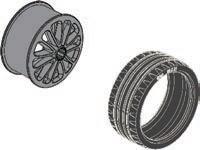
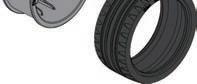
• Consult the dealer or an experienced radio/TV technician for help. Caution: changes or odifications not e pressly appro ed y the party responsi le for co pliance could oid the user’s authority to operate the equipment.
To comply with the FCC RF exposure compliance requirements, this device and its antenna must not be co-located or operating in conjunction with any other antenna or transmitter. For body worn operation, this device has been tested and meets FCC RF exposure guidelines when used with an accessory that contains no metal and that positions the device a minimum of 20 cm from the body. Use of other accessories may not ensure compliance with FCC RF exposure guidelines. Shielded cables must be used with this unit to ensure compliance with the Class B FCC limits.
NOTE: This equipment has been tested and found to comply with the limits for a Class B digital device, pursuant to part 15 of the FCC Rules. These limits are designed to provide reasonable protection against harmful interference in a residential installation. This equipment generates, uses an can radiate radio frequency energy and, if not installed and used in accordance with the instructions, may cause harmful interference to radio However,communications.thereis
4
IC Statement RF Radiation Exposure Statement: This equipment complies with IC radiation exposure limits set forth for an uncontrolled environment. This equipment should be installed and operated with minimum distance 20 cm between the radiator and your body. This transmitter must not be co-located or operating in conjunction with any other antenna or transmitter.
• Reorient or relocate the receiving antenna.
1246R Instruction Manual https://build.t2t.io/ur?qr=r1U0HVsVL
Warning: Changes or modifications to this unit not expressly approved by the party responsible for compliance could void the user’s authority to operate the equipment.
FCC Part 15 Statement
(1) this device may not cause harmful interference, and (2) this device must accept any interference received, including interference that may cause undesired operation.
no guarantee that interference will not occur in a particular installation. If this equipment does cause harmful interference to radio or television reception, which can e deter ined y turning the e uip ent o and on the user is encouraged to try to correct the interference by one or more of the following measures:
Operation is subject to the following two conditions:


5
Enter the world of programming blocks
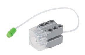
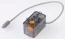
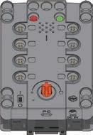
D.The light sensor is able to detect changes in the amount of light. It transmits this information to the app.
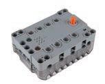
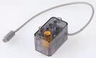
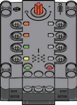
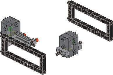
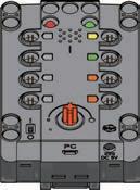
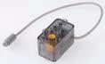
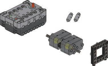
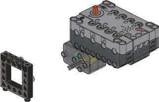
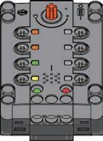
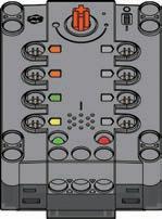
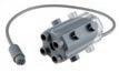
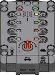
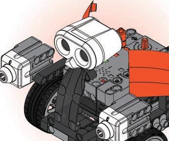
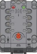
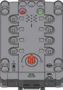
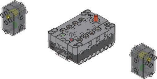
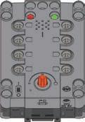
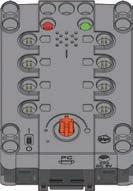
A.The Gigo Smart Control Box connects to the app on your tablet via Bluetooth. It distributes instructions to the motor units via wires. It also has a wired connection to the sensor units and transmits their input data back to the tablet app. In addition, the Gigo Smart Control Box has a microphone that can be used to detect sounds, a speaker to make sounds, and a variable resistor input (rotary knob).
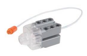
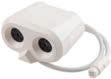
E.The force sensor like your fingers is a le to sense if it has co e into contact with an object. It transmits this information to the app.
-The toy is only to be connected to equipment bearing either of the following symbols.
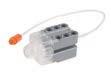
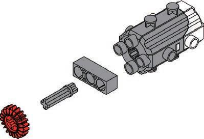
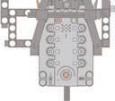
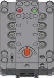
or A LED USB port UltrasonicBuzzer sensor Motor 4 Illuminance sensor Motor 3 Motor 2 Motor 1 Force sensor 1 Force sensor 2Control knob DC 5V input MicrophoneswitchPower Power indicatorconnection
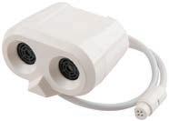
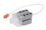
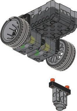
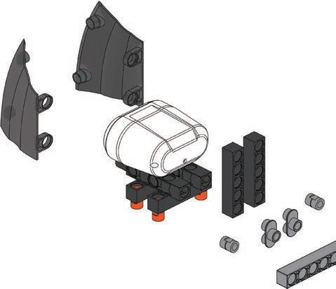
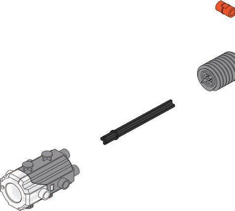
B.Motor units 1 and 2 connect to axles and motor shafts to power gears and wheels, bringing your models to life. They receive power from the Gigo Smart Control Box. C.The ultrasonic sensor sends out ultrasound waves and “listens” for the to ounce o of o ects t trans its this information to the app, enabling it to estimate distances to an object.
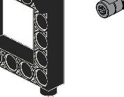
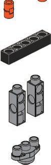
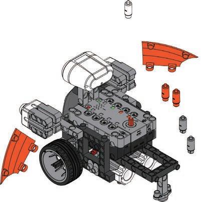
Primary Components B C D E F
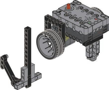
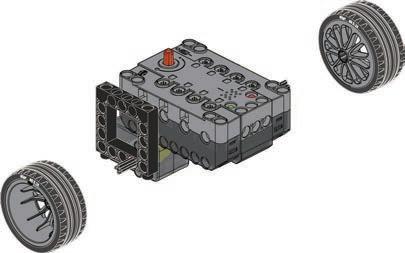
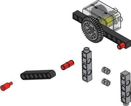
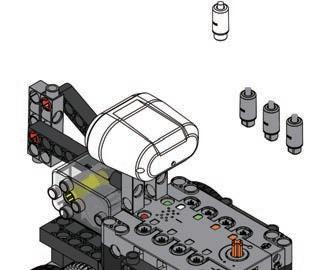
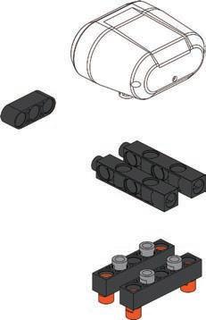
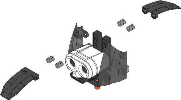
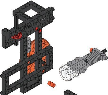
Preparation I
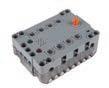
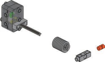
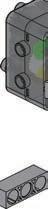
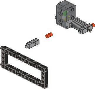
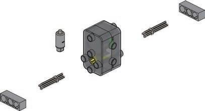
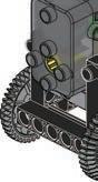
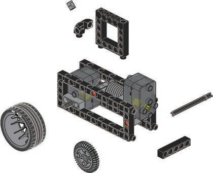
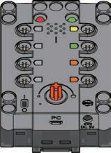
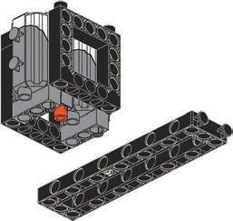
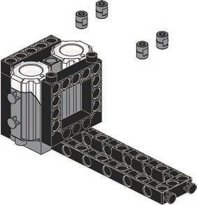
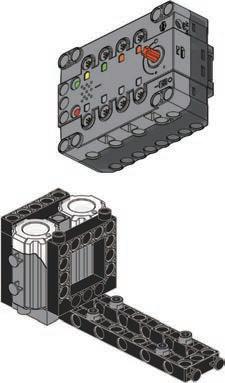
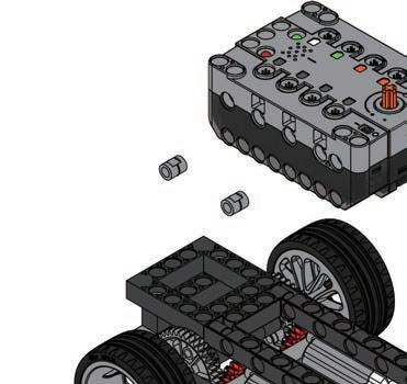
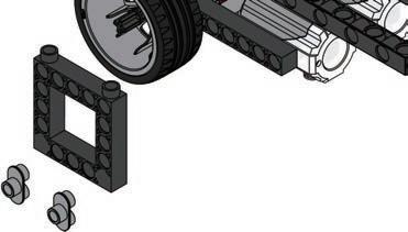
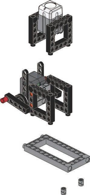
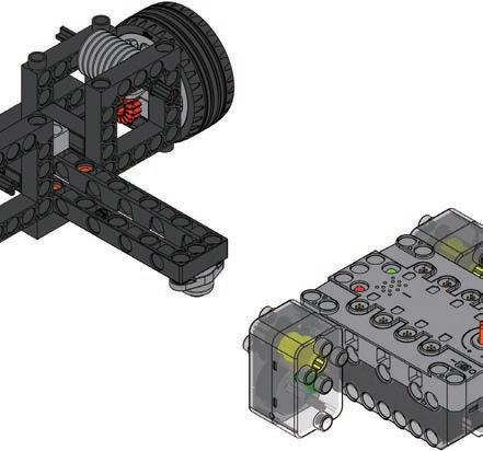
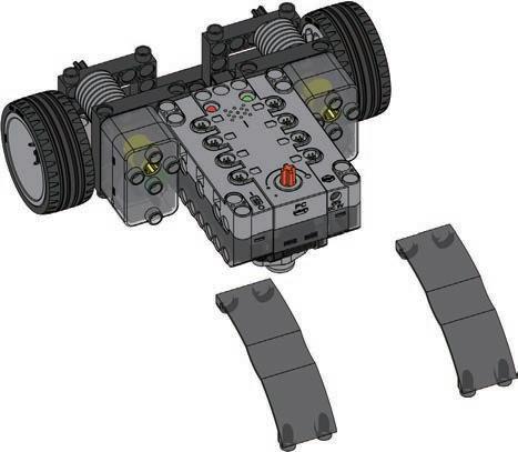
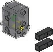
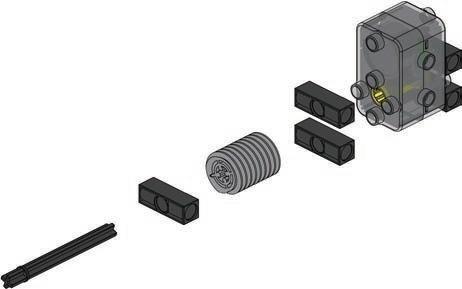
Installing batteries in the core controller
B
Push the tab in and slide the transparent cover open. This takes some force, so an adult might need to help. Insert the batteries according to the indicated plus-minus polarity. Close the compartment by snapping the cover back on.
F.CB1 GigoBlockly: The mobile app (or desktop PC application) communicates with the control box to form the “brain” of your robotic models. It uses feedback from the sensors, along with your programmed instructions, to give your models the instructions they need.


The CB1 GigoBLOCKLY app was developed on Android 6.0. It is expected to work on Android 5.x or 4.4, but compatibility cannot be guaranteed for all devices.
1. In a web browser on your tablet, navigate to the Robotics Workshop product page on the Gigo website. https://blockly.t2t.io/gigo
• Android devices must support Bluetooth 4.0 or above, and must be running Android 4.4 or later. A display of 9.7 inches or larger is recommended. Because of the variety of devices in the Android ecosystem, it is impossible to recommend a specific ndroid de ice
The GigoBLOCKLY CB1 app can be downloaded from the iOS app store, or Google Play, depending on your device.
THE MOBILE APP TO THE Gigo SMART CONTROL BOX
• Minimum system requirements: Dual core processor, 2.4 GHz (i5 or i7 Intel processor or AMD equivalent); 4 GB RAM; 100 MB free hard drive space for the application files; 802.11g/n wireless (for laptops; WPA2 support is required); 19-inch LCD monitor (for desktops).
To find, download, and install the app:
• The desktop app is not supported on all computers. A Windows desktop or laptop PC with a USB 2.0/3.0 port and Internet connection are required. NOTE: The CB1 GigoBlockly desktop application was developed on Windows 10. It is expected to work on Windows 7 or higher, but compatibility cannot be guaranteed.
• iOS devices must support Bluetooth 4.0 or above and Mac computers must be running iOS 8 or later, though iOS 9 or 10 is recommended. Supported devices include 3rd gen iPads or later, the iPad mini, iPad Air, and iPad Pro. An iPad display of 9.7 inches or larger is recommended.
INSTALLING
The GigoBlockly App
TROUBLESHOOTING THE CONNECTION
2. Click the link to download the CB1 GigoBlockly Desktop application. Download and run the Useinstaller.theincluded USB cable to connect the Gigo Smart Control Box to the computer.
››› Make sure the sensor and motor cables are securely plugged into the Gigo Smart Control Box.
Preparation II
CB1 GigoBlockly DESKTOP INSTRUCTIONS
f you are ha ing trou le connecting to the igo art ontrol o first try closing and then reopening the app.
››› Exit the program you are in and relaunch it. Or try a different program.
3. Follow the steps on the app page to download and install the app on your device
6
1. In a web browser, navigate to the Robotics Workshop product page on the Gigo website.
If the connection isn’t working: ››› Disconnect and then reestablish the Bluetooth connection.
To find, download, and install the app on your PC:
CONNECTING
2. There are links to the app pages on the iOS App Store and Google Play store. Follow the link to the appropriate store for your device. Alternatively, you can search for “CB1 GigoBlockly” or “Robotics Workshop” in the app store.
THE MOBILE APP (CB1 GigoBlockly)
The mobile app will automatically connect to the Gigo Smart Control Box via Bluetooth. Make sure that Bluetooth is enabled on your mobile device and that the Gigo Smart Control Box is turned on.


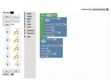
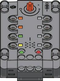
The main user interface of the CB1 GigoBlockly App for Robotics Workshop is shown above. The primary features are: A. CB1 GigoBlockly status indicator: This changes color when the Gigo Smart Control Box is connected to the app. It blinks when there is activity between the Gigo Smart Control Box and the app.
CB1 GigoBlockly is a visual programming tool built using the opensource oogle lockly li rary t is configured to interact with the Gigo Smart Control Box in this kit. The app uses visual blocks of code that can e easily inserted o ed configured and deleted he goal of GigoBlockly is to make it easy to produce programs that let you control your devices, the way you want them to be controlled.
AB EF
Block Toolbox and Block Coding Area D CA B
7 Enter the world of programming blocks
Writing Programs
Step: This button allows you to run through the code blocks one by one, to see the e ects of each step his is useful when de ugging new progra s
E. Save and load programs: To save a program, choose one of the programs listed in the menu and then press the save button. To load a previously saved program, choose one of the programs from the menu and press load. The program will load into the block coding area.
B. CB1 GigoBlockly code blocks: This part of the toolbox contains all of the code locks that were de eloped specifically for use with the igo art Control Box in this kit.
F. Load demo code: To load the demo program for one of the ten robotic models included in this manual, simply tap menu and select the demo program you want.
A. Block toolbox: Tap one of the category names in the block toolbox to show the code blocks available in that category. This toolbox contains all of the common blocks of code that you will need.
The main CB1 GigoBlockly app interface
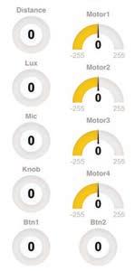
D. Motor status display: These gauges show the real-time output of each of the four motors (speed and direction).
This is the main coding area where you can assemble programs to control your robots.
B. Program operation buttons: Parse: This button validates the code and uploads it to the Gigo Smart Control Box. Run: This button runs, or executes, the program on the Gigo Smart Control Box.
C. Sensor status display: These gauges display real-time readings from the sensors plugged into the Gigo Smart Control Box: Distance: Ultrasonic sensor input Lux: Light sensor input Mic: Sound sensor (microphone) input Knob: Rotary knob (variable resistor) input Button 1 and 2: Touch sensor input
FEATURES OVERVIEW
C Preparation III A
Reset: This button removes the program from the Gigo Smart Control Box so that a new program can be uploaded.
C. CB1 GigoBlockly coding area: his is where you asse le and configure the code blocks into the active program. PP OV
ERV IE W
Stop: This button stops the entire program from running.


This manual does not explain the function of every block in the Blockly library. The educational intent is for you to learn how many of the blocks function by building the models in this manual, loading the demo code for each model, and experimenting with how the demo code functions with each odel f you ha e a uestion a out a specific code lock we suggest you look it up online with the help of an adult. Because Blockly is open-source, there is a considerable amount of information available about it online. The CB1 GigoBlockly blocks are explained below.
E. Sensor Blocks
The LED blocks allow you to program the LEDs on the Gigo Smart Control Box.
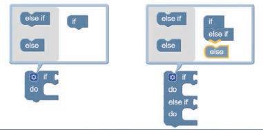
CREATING IF-ELSE STATEMENTS
As you will learn, if-else and if-else-if-else function blocks are important to many programs. To create an if-else block, tap on the small blue gear on an if block. Drag an else-if or else block to the right side of the window to make a new type of block. A B C D
The buzzer blocks allow you to play sounds from the speaker on the Gigo Smart Control Box.
Sensor blocks allow you to use the sensor input data in your programs. With the sensor blocks, you can choose to get sensor data from the ultrasonic sensor (distance), light sensor (luminance), sound sensor (microphone), touch sensors (button 1 and 2), and the rotary variable resistor (knob). You can also plug the sensor blocks into logic blocks.
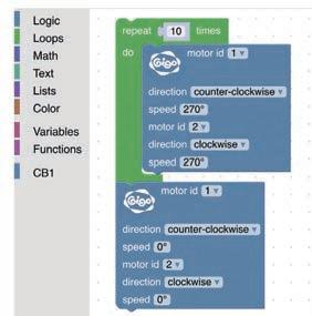
You can modify the existing demo programs or write your own. Here’s Taphow:one of the sections in block toolbox (A). This will open a bar which shows all the functions within that menu (B). Then drag and drop one of the blocks into the center of the coding area. Blocks can be connected and placed within one another to form nested blocks of code. Code blocks can also be stacked on top of one another.
8
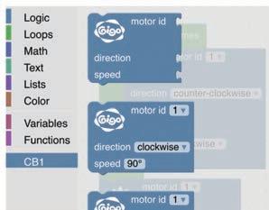
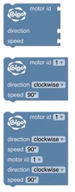
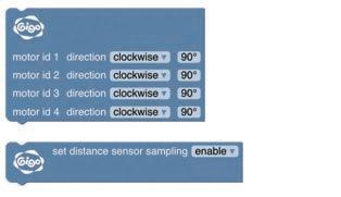
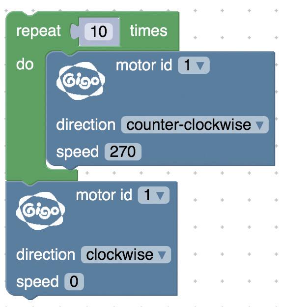
Use the motor blocks to control one to four motors. You can select which motor port you want to control with the block, and set the direction and the relative speed (power level) you want.
C. Buzzer Blocks
WRITING A PROGRAM
B. Distance Blocks
ABCED Preparation III
D. LED Blocks
The distance block allows you to measure the distance between an object and the model when it is enabled.
Important: When you run the program, the app will carry out your code from top to bottom, starting at the top. You can change the variable parameters or values in the code blocks by tapping on the enus or fields You can duplicate, collapse, disable, or delete a code block by using press-and-hold to enter the edit menu (D).
CB1 GigoBlockly A. Motor Blocks


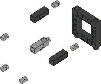
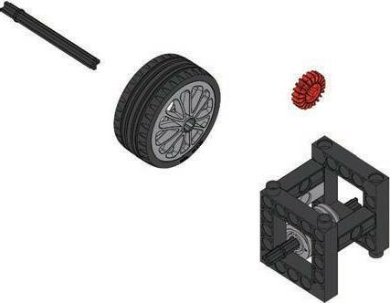
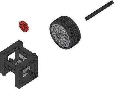
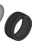
9 Parts List 1 2 3 4 5 6 7 8 9 10 11 12 13 14 15 16 17 18 19 20 21 22 23 24 25 26 27 28 29 30 31 32 33 34 36 37 38 39 3540 41424344 45464748 50 49 51 52 53 54 55 56 x50 x30 x21 x12 x12x8 x2 x2x2 x5 x5 x12 x6 x6 x5 x4x3x1 x2 x5 x7 x11 x3 x2 x2 x2 x1 x11 x2 x4 x6 x4 x3x2x9 x4 x6x3 x2x3 x2 x2x1 x2 x1x1 x1 x1 x1 x1 x2 x2 x2x1 x3 x1x1x1 60 5961 5758 x1x1 x1 626364 65 x1x2 x2 x1


10 Checklist: Find – Inspect – Check off 1 B-SHORT PEG 50 2 C-LONG PEG 30 3 C-20mm AXLE CONNECTOR 21 4 C-AXLE 12 5 C-CAM CONNECTOR 8 6 C-TWO-IN-ONE CONVERTER 12 7 C-LATERAL CONVERTER 2 8 C-FRONT CONVERTER 2 9 C-BENDED ROD 2 10 C-3 HOLE ROD 5 11 C-3 HOLE ROD FRONT CLOSED 5 12 C-3 HOLE DUAL ROD 12 13 C-3 HOLE ROUND ROD 6 14 C-5 HOLE ROD 6 15 C-5 HOLE ROD FRONT CLOSED 1 16 C-5 HOLE DUAL ROD BOTTOM CLOSED 3 17 C-5 HOLE DUAL ROD 2 18 C-7 HOLE ROUND ROD 5 19 C-7 HOLE WIDE PROLATE ROD 5 20 C-9 HOLE ROD 4 21 C-11 HOLE ROD 7 22 C-15 HOLE DUAL ROD 3 23 C-5X5 FRAME 6 24 C-5X10 FRAME 2 25 C-3X13 DUAL FRAME 2 26 C-5x13 DUAL FRAME 3 27 C-5X15 FRAME 4 28 C-MOTOR AXLE 6 29 C-35mm AXLE Ⅱ 4 30 C-65mm AXLEⅠ 2 31 C-70mm AXLE Ⅱ 11 32 C-100mm AXLE Ⅱ 1 33 C-20T GEAR 11 No. Description Item No. Qty. 34 C-40T GEAR 9 35 C-60T GEAR 2 36 C-80T GEAR 3 37 C-WORM GEAR 4 38 C-ROD CONNECTOR 3 39 C-TURBO TIRE 2 40 C-TURBO TIRE RIM 2 41 C-SHELL A LEFT 1 42 C-SHELL A RIGHT 1 43 C-SHELL A LEFT 1 44 C-SHELL A RIGHT 1 45 C-SHELL C 2 46 C-SHELL F 2 47 C-SHELL E 2 48 C-VIBRO LEFT LEG 1 49 C-VIBRO RIGHT LEG 1 50 B-HORN PIECE 2 51 C-WASHER 2 52 C-AXLE FIXING 1 53 C-POLYSTYRENE BALL 3 54 C-70mm RUBBER BAND 1 55 B-PEG REMOVER 1 56 C-BALL ROLLER 1 57 C-MicroUSB 2.0 CABLE 1 58 C-EXTENSION CO RD 1 59 C-ULTRASONIC SENSOR 1 60 C-40X MOTOR WITH WIRE CONNECTOR(DDM) 2 61 C-32X PLANETARY GEARBOX(DDM) 2 62 C-ILLUMINANCE SENSOR 1 63 C-FORCE SENSOR 2 64 P-LABEL 1 65 C-Gigo SMART CONTROL BOX 1 No. Description Item No. Qty. 7026-W10-D2R7413-W10-L2D7061-W10-Q1D7416-W10-C1D7413-W10-O1D7026-W10-L1S17413-W10-J1D7061-W10-U1D7406-W10-A1D7413-W10-I1S17413-W10-Q1D7413-W10-Z1D7413-W10-P1D7407-W10-C1S7404-W10-C3D7404-W10-C2D7413-W10-X1D7413-W10-W1S17413-W10-R1S17413-W10-K2D7404-W10-C1D7413-W10-Y1S27026-W10-X1D7026-W10-Q2S17061-W10-V1D7061-W10-Y1D7061-W10-X1D7061-W10-G1S27413-W10-S1R7026-W10-H1O17413-W10-T1R7061-W10-C1O7344-W10-C2S 1246-W85-A1R20#1246A-21246-W85-C1246-W85-B7392-W85-B37400-W85-A17416-W85-B1246-W85-DE30#1247A1247-W85-C1S7061-W10-B1YR10-02K30#7366-23620-W10-A1DR12#36207128-W10-G1O7397-W10-C2D7397-W10-C1D7398-W10-C2TD7398-W10-C1TD7392-W10-M1O7392-W10-L2O7392-W10-L1O7392-W10-L2TD7392-W10-L1TD7407-W10-B1S7407-W10-A1D7026-W10-L2D7344-W10-A1S17328-W10-G2O7026-W10-W5S7346-W10-C1S
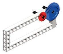
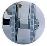
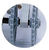
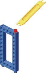
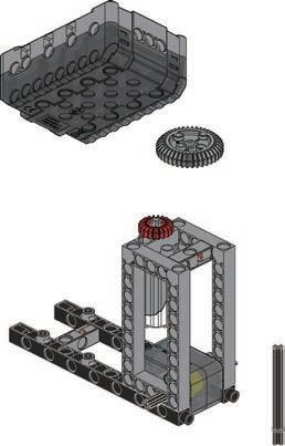
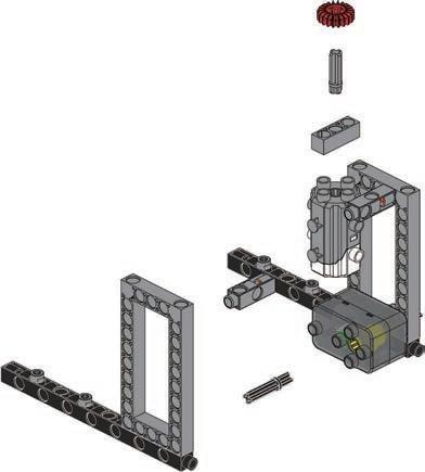
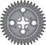
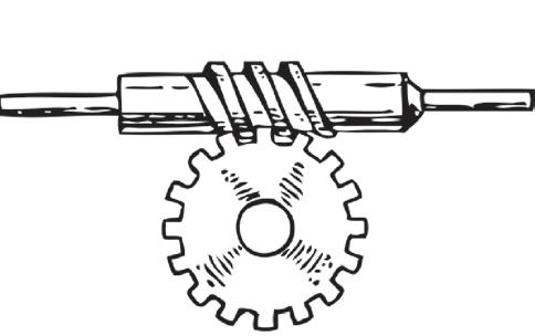
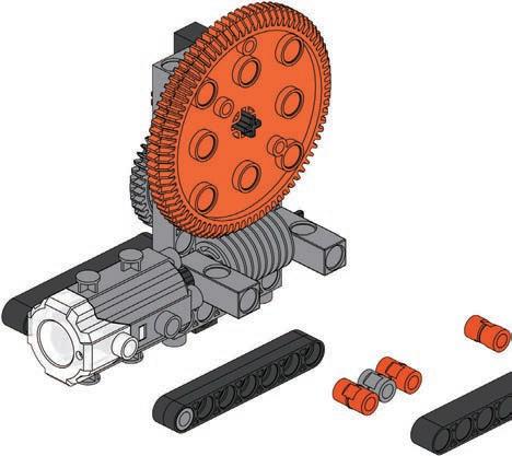
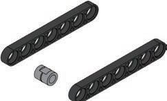
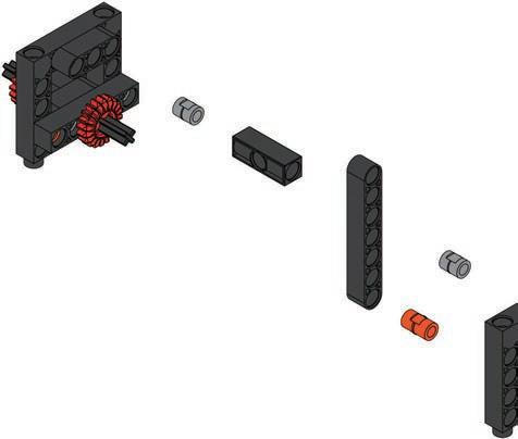
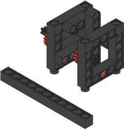
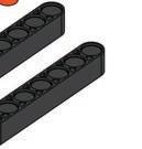
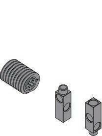
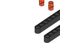
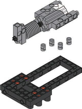
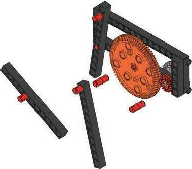
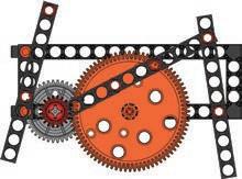
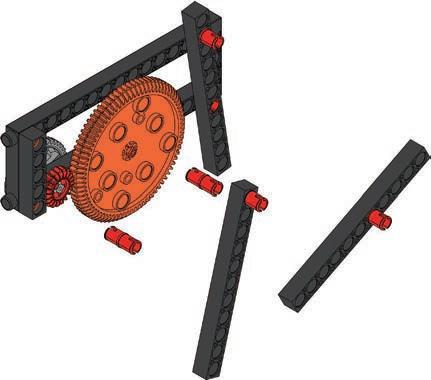
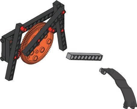
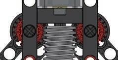
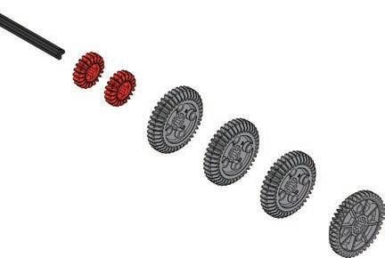
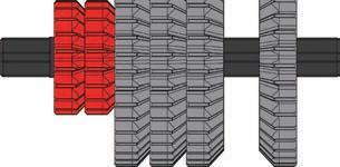
TIPS AND TRICKS : When fi ing gears onto the fra e with dri e axle be sure to keep a proper space (about 1mm) between the gear and the frames (Fig. 2). And try to turn the gear to ensure every gear in the gear train turning smoothly so that the least friction will e created and ost e cient power transmission can be expected. sing peg re o er to pull peg o as Fig.3 shows. sing peg re o er to pull a le o as Fig.4 shows. The models will often have several gear wheels installed in a row, or gear train. In order for the models to work well, thesae gears will have to mesh well. Otherwise, the force from one gear wheel won’t be properly transferred to the next. A. Pay attention to the hole: B. B-Peg remover: C. Gear wheels: Here are a few tips for assembling and using the models. Read them carefully before starting. NG! (without space) OK! (with space) For more tips,pleaseassemblyreferto Fig.1 Fig.3Fig.2 Fig.4


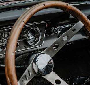
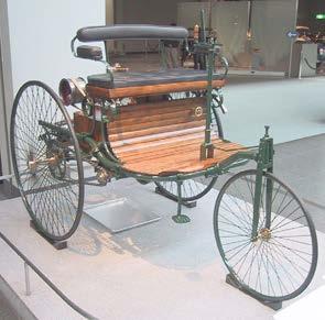
11 Brainstorming Cars are so common nowadays that we can easily forget how amazing they are. Do you know who invented the first car? It was Karl Friedrich Benz (yes, that Benz). He was a er an engineer and uilt the world s first three wheeled vehicle that used an internal combustion engine. fter en ottlie Wilhel ai ler ade the first four wheeled car. Later, the American Henry Ford found a way to mass produce affordable cars, and at the same time revolutionized industrial production methods. Since then cars have become more common.
Autonomous cars appear in many modern movies and TV shows, but autonomous vehicle experiments actually began in the 1920s. Self-driving cars, as the name implies, can move without human intervention. They sense the environment using radar infrared sensors or lasers and respond using artificial intelligence The computer system analyzes the sensing data and converts it into a navigation roadmap. The self-driving cars follow the sensor data and respond automatically.
1 Daily
The Society of Automotive Engineers (SAE) and the National Highway Traffic Safety Administration (NHTSA) classify autonomous driving into five levels based on different degrees of driver assistance. Level zero is the earliest general mechanical vehicle and needs to be controlled by humans the entire time. Levels 1 to 5 describe increasing amounts of automation. Level 5 is a fully autonomous vehicle that can start the driving by itself without human control, and it can make decisions. Although fully autonomous cars have not been used so far, some technologies related to self-driving have been gradually introduced. Self-driving electric cars are now available to purchase and self-driving technology will continue to improve.
What are the pros and cons of self-driving cars? Application Car Autonomous Driving Scientific Application


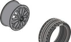
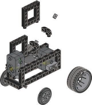
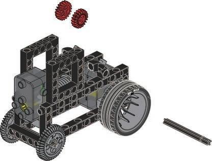
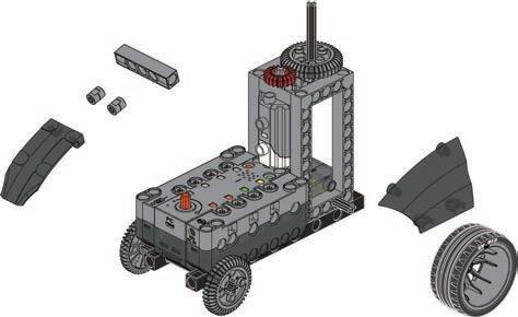
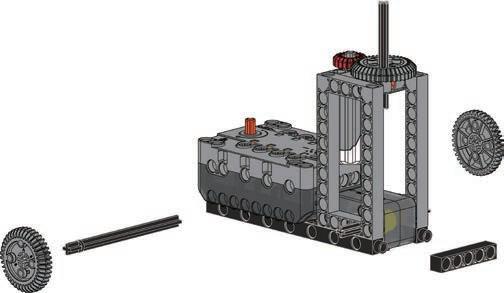
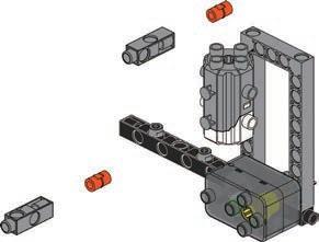
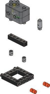
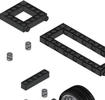
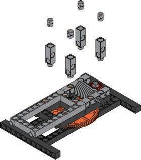
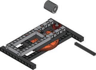
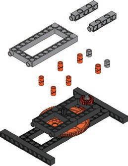
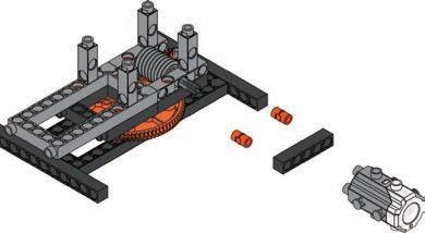
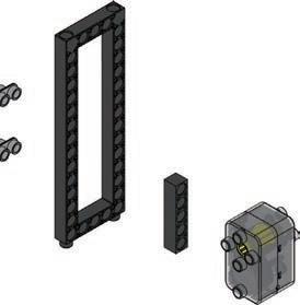
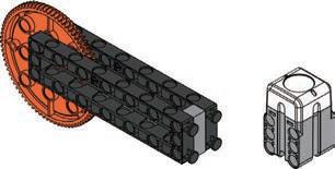
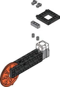
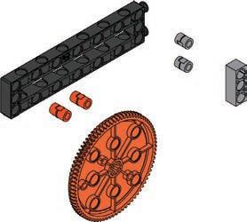
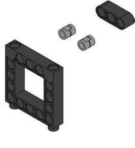
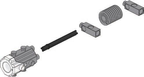
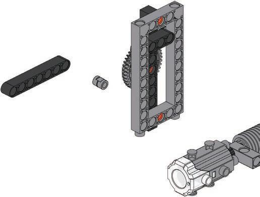
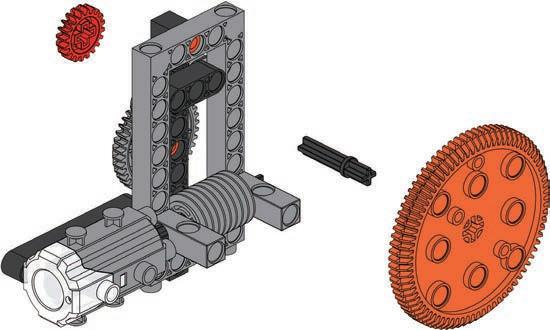
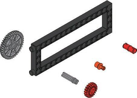
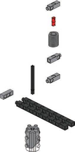
12 Parts List 5 3 4 6 1 2 x8×2 1 x2 26 x2 34 x1 31 x1 41 x2 40 x1 42 x2 10 x1 60 x2 39 x2 29 x1 14 x1 65 35mm 35mm 70mm


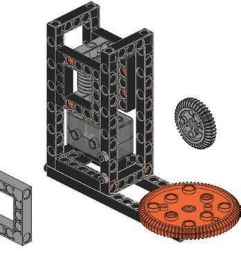
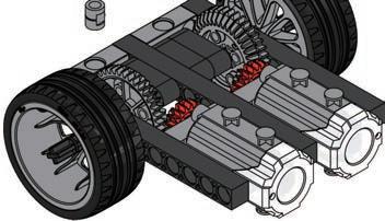
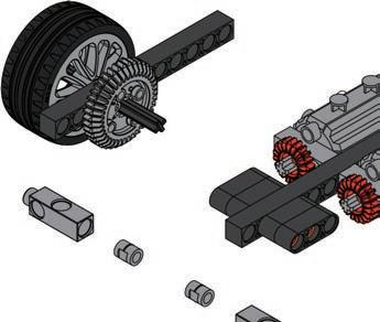
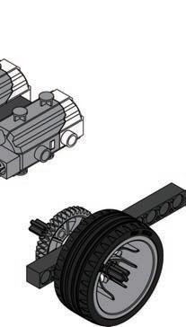
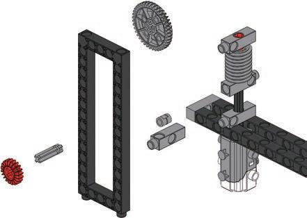
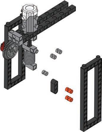
13 Car1 7 9 8 Done Program Example motor A motorA motor A OperationModelVideo


1 2 3 14 Smart Manual Web Service ExperimentHands-on CreativityHands-on Evaluation AssembledModel ExperimentComplete CreationModel Modify your car so it can go forward and backward on its own. Change your program to make your car move forward and backward more quickly.
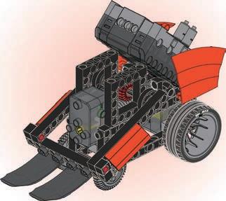
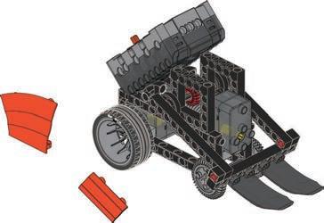
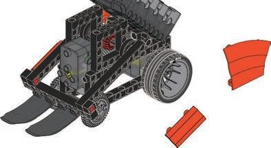
Bulldozer
The crawler bulldozer is the type of machine that we often think of when we just say bulldozer. They used to operate using steam power, but since the development of the internal combustion engine, they use diesel fuel as it has much more power, and it is ore e cient odern ulldo ers also use a special kind of gear trans ission called hydraulic mechanical transmission. Hydraulic mechanical transmission is a connected transmission system that uses an impeller to convert mechanical energy into liquid kinetic pressure. This pressure is then turned back into mechanical energy at the point where the force is needed. Liquid is used as a medium to transfer energy as it is nearly lossless and ery e cient howe er these syste s are uch larger and heavier. Hydraulic mechanical transmission improves the operating performance of the drive system, making it easier to control the vehicle. It also helps heavy machinery to start moving, accelerate and push heavy objects.
Where can you see bulldozers? What are their main features? What are the functions of those features?
2 Bulldozers are one of the most important machines in civil engineering. They are divided into two types - crawlers and tired – depending on how they move. Before the invention of the steam engine, there was a tool similar to the bulldozer, which used horses to pull a “moldboard”.
15 Brainstorming
Daily Application
Hydraulic TransmissionMechanicalScientific Application
Bulldozers are relatively simple to operate and when they have tracks they are highly mobile. They can move quickly, but do not accelerate quickly. Their power and mobility make them important in civil engineering. There is a large curved spade on the front that can be used to dig, bulldoze, and transporting silt or stones. Bulldozers are mainly used for site clearing and leveling (grading), but they can also be used for excavating and building a foundation. For example, in road construction, in addition to removing obstacles and piled materials, construction workers use bulldozers to build the subgrade and level the site.


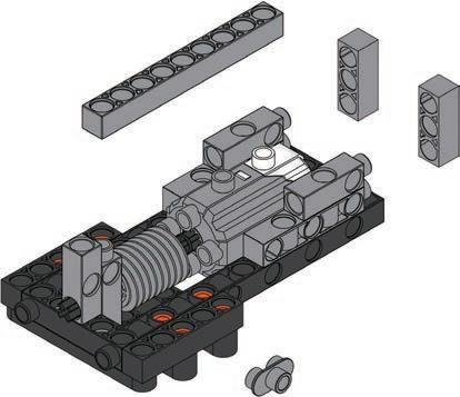
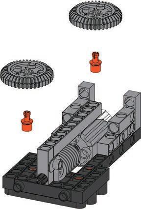
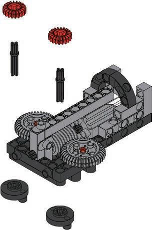
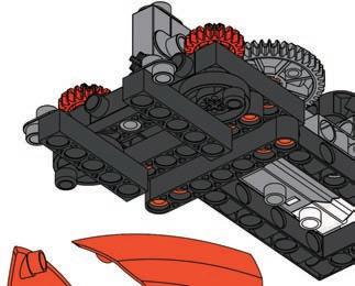
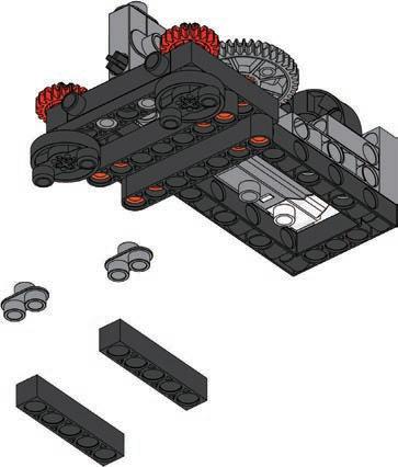
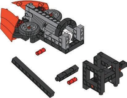
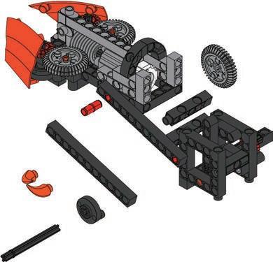
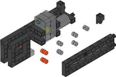
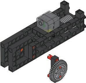
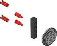
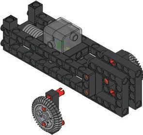
16 5 3 4 12 6 ×235mm 35mm 70mm 70mm 70mm Top view 9 7 8 Parts List x6 1 x2 34 x3 31 x1 43 x2 40 x1 44 x3 10 x2 60 x2 39 x2 29 x1 14 x1 65 x2 2 x2 3 x2 7 x2 9 x2 12 x3 21 x2 23 x2 26 x2 33 x2 45 x2 38 x1 37 x2 47


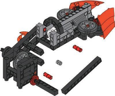
10 Done16 Program Example 11 12 13 14 15 17 Bulldozer2 OperationModelVideo motor B motormotorAA motor A motorB motor B


1 2 3 18 Smart Manual Web Service ExperimentHands-on CreativityHands-on Evaluation AssembledModel ExperimentComplete CreationModel Use your bulldozer to push items such as erasers, pencils and coins. Modify the model by replacing the worm drive of the bulldozer with a gear set, and test whether it can lift heavy objects.
Daily Application
Space exploration refers to “physical space exploration outside Earth’s atmosphere”. During the Cold War, the United States and the Soviet nion were highly co petiti e in any fields
What galaxy do we live in? What planets or star systems are there in this galaxy? Why do humans want to explore Mars? 3 Mars is one of the eight planets of our solar system, and it’s the fourth planet from the Sun. Of the eight planets, Mars is the closest to Earth, after Venus. Space research is primarily performed by astronomers using telescopes, but physical space exploration can be carried out and is done in two ways. The first is by unmanned robots, and the other is by human astronauts.
n the ariner was the first pro e in history to successfully reach ars er the next fifty years, more than thirty detectors were launched and reported data Marssuccessfully.exploration
The “Space Race” between the two concerned developments in science and technology, and became the origin of space exploration. After the end of the Cold War, countries began to cooperate willingly. In recent years, private business companies have even developed space tourism and private lunar space travel. In the 20th century, the knowledge gained from space exploration exceeded the sum of knowledge gained over thousands of years. Despite this increase in knowledge and technology, it seems that human curiosity a out space and the unknown will ne er e satisfied
is not a simple task. Over the past 50 years, more than half of the Mars exploration programs have failed. The silver lining to this grey cloud however has been great leaps in technology and innovation. Some unmanned Mars missions have succeeded, so let's explore the universe together now!
Space ExplorationScientific ApplicationMars Rover
19 Brainstorming


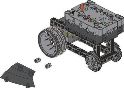
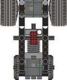
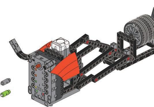
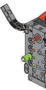
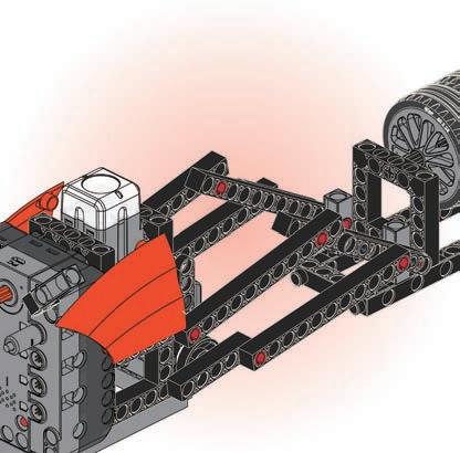
20 Parts List 3 5 3 4 6 12 ×2 100mm x8 1 x3 34 x1 31 x2 40 x1 10 x1 60 x2 39 x2 29 x1 14 x1 65 x2 2 x2 9 x2 12 x2 23 x2 26 x1 33 x1 37 x1 47 x1 15 x2 22 x1 28 x1 32 x1 41 x1 42 x1 36 x1 61 ×2 35mm 70mm7 35mm Front view 8


21 Mars Rover3 Done 9 10 11 motor A motor B motor A motorBmotorBmotorA Program Example OperationModelVideo


1 2 3 22 Smart Manual Web Service ExperimentHands-on CreativityHands-on Evaluation AssembledModel ExperimentComplete CreationModel Observe how the Mars Rover moves on different surfaces such as the table and the ground. Change the program to let the detection device of the Mars Rover operate in clockwise and counterclockwise directions.
One of the basic functions of a robot is to avoid obstacles if we want it to be able to move freely.
Obstacle avoidance means that the robot senses obstacles along its chosen route by using sensor data. It must be able to balance and walk, and sense, calculating everything as it moves. It must also be able to plan ahead, choosing an appropriate path to bypass any obstacles so it can reach its destination. Whether the mission is navigation planning or obstacle avoidance, accurately detecting the surrounding en iron ent is an i portant first step
Obstacle Proximity Sensor Scientific ApplicationSensorProximity
Proximity sensors on cars can sense obstacles and avoid them with the help of sensors. How can humans avoid and dodge obstacles if they don’t have infrared or ultrasonic sensors?
4
23 Brainstorming
Obstacle avoidance robots receive information about obstacles through their sensors. There are various kinds of obstacle avoidance sensors with different principles and characteristics. At present, the most common are infrared, ultrasonic laser range finders ca eras and et s design a car with an obstacle proximity sensor! Daily Application
Car
Obstacle proximity sensors are widely used on mechanical devices. For example, sweeping robots may use a laser distancing system and navigation computer code to make an indoor map of an apartment. From this they can establish positional relationships between their map and objects in the room. Some sweeping robots use infrared sensors for navigation. In addition to the intelligent obstacle avoidance function, a purpose built Integrated Circuit (IC) can be used to store an algorithm for navigation. The chip can include basic obstacle avoidance functions and other helpful things like fall prevention and climbing skills, so that not everything has to be done with computer code.


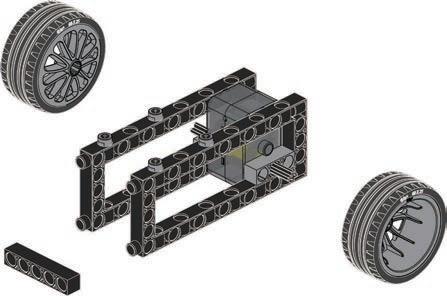
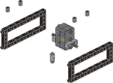
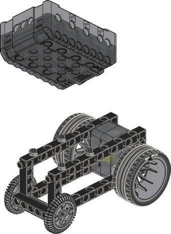
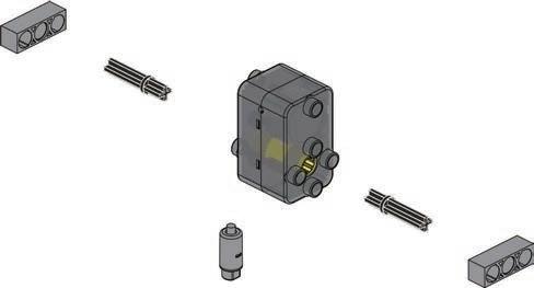
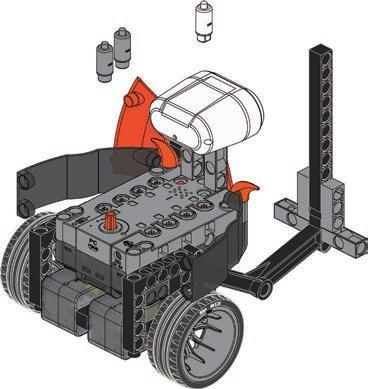
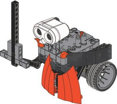
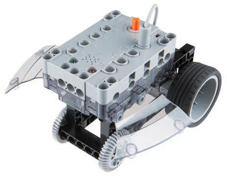
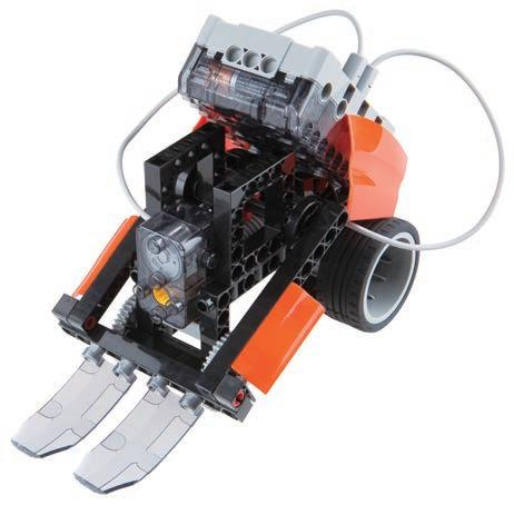
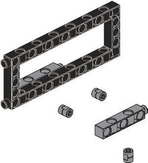
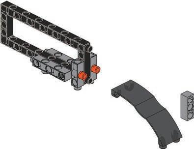
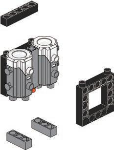
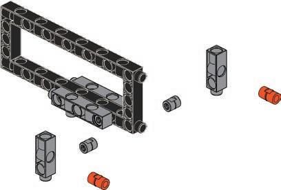
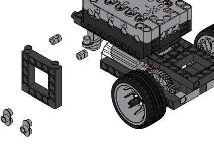
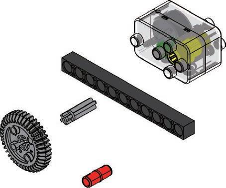
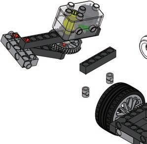
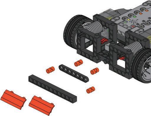
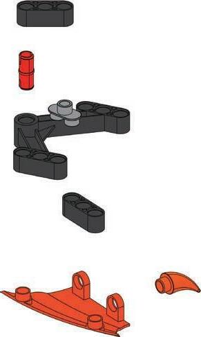
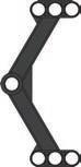
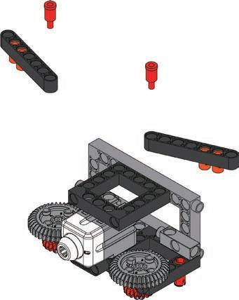
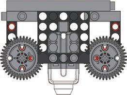
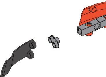
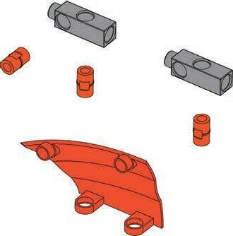
24 Parts List x14 1 x2 40 x2 10 x2 39 x2 29 x2 14 x1 65 x2 2 x6 12 x2 23 x1 48 x1 49 x2 50 x1 56 x1 59 x2 60 x2 46 x1 21 x1 43 x1 44 1 2 5 3 4 1235mm 35mm ×2 9 10 ×2 7 8 6 2 or 4 2 or 4 2 or 4 1 or 3 1 or 3 1 or 3


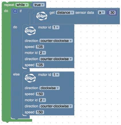
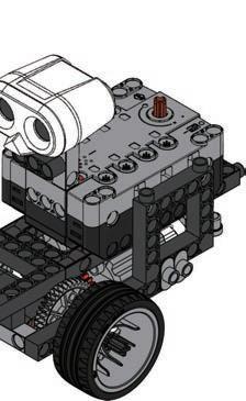
motor B motor A 25 Car Proximity Sensor4 OperationModelVideo Done motormotorA B Program Example 12 13 11 SensorUltrasonic Ultrasonic SensorUltrasonicSensor motor A motor B


1 2 3 26 Smart Manual Web Service ExperimentHands-on CreativityHands-on Evaluation AssembledModel ExperimentComplete CreationModel Place some obstacles in front of your car and observe how it reacts to them. Change the program by replacing the deviate left command with deviate right.
27 ReviewModel 1. Car 3. Mars Rover 2. Bulldozer 4. Car Proximity Sensor Use the models and principles you’ve learned to design a sweeping robot. 5 Monograph 1


2 31 28 ConceptDesign CreationModel Winner!DesignModel My Artwork Evaluation


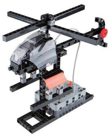
What are the si ilarities and di erences etween airliners and helicopters? a e you e er drea ed of ying free in the sky like a bird? Flying has long been a pursuit of Afterhumans.the industrial revolution, with the increases in productivity and progress of civilization, technology allowed many of mankind’s dreams to come true. By 1903, the first fixed-wing aircraft made by Wilbur and Orville Wright flew successfully. In 1907, the Frenchman Paul Cornut developed a full-size manned helicopter, the first of its kind What is the principle of helicopter ight When the helicopter starts, the rotor spins and generates a downward airflow. The relationship between the airflow and ground generates forces and reaction forces. That force becomes the helicopter’s lift.
29 Brainstorming
Now, let’s look at the operating principles of helicopters in this lesson! Flight Scientific Application
6 Daily Application Helicopter Principles of
There are two kinds of helicopters: civilian and military. 1. Civilian helicopters are used for medical rescue, emergency rescue, geological exploration, aerial photography, short-distance transportation, agriculture, and sightseeing. There are no weapons on the civilian helicopters. 2. Military helicopters are used for weapon transportation logistic support attlefield rescue ilitary attack, rescue missions and disaster relief. They are loaded with armor and weapons, and they are higher performance than civilian helicopters.


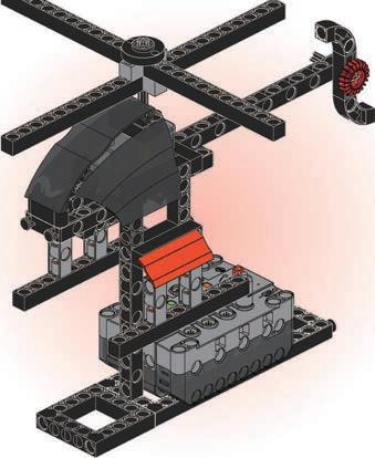
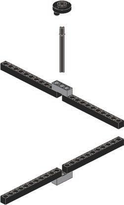
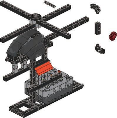
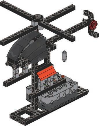
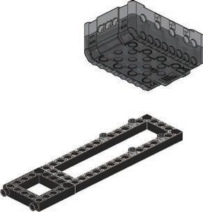
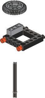
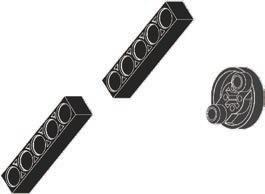
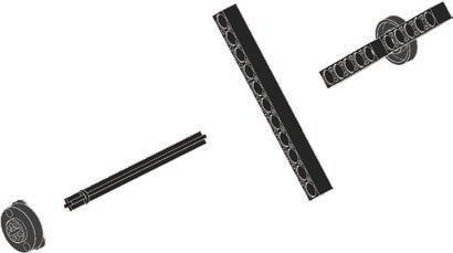
30 Parts List x2 13 x16 1 x1 31 x2 10 x1 60 x1 38 x1 29 x3 14 x6 21 x2 22 x1 65 x4 2 x2 9 x4 12 x2 11 x3 23 x1 25 x1 27 x1 33 x1 46 x2 45 x1 41 x1 42 5 6 3 4 2 1 27 25 10 7 8 42 41 9 11 ×2 ×2


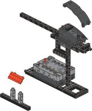
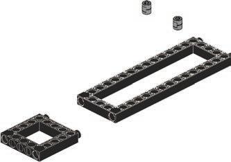
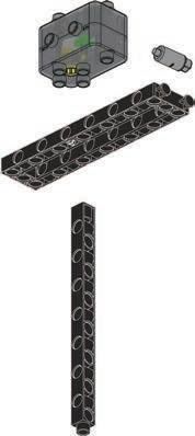


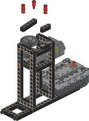
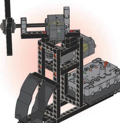
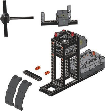
Done 35mm 70mm 1213 15 14 Program Example 31 6 Helicopter OperationModelVideo motor A motor A motor A


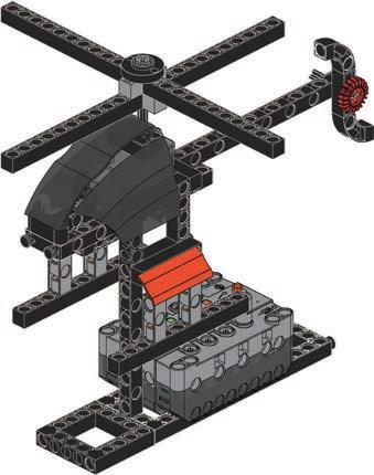


1 2 3 32 Smart Manual Web Service ExperimentHands-on CreativityHands-on Evaluation AssembledModel ExperimentComplete CreationModel Use sound to make the rotor blades start and stop. Change the program and use volume to control the speed of the helicopter’s rotor.
33 Brainstorming
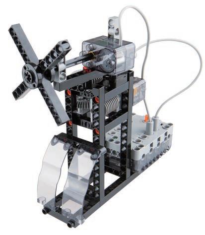
Which kinds of electric fan have you seen? What is the difference between electric fans on the ceiling, those on the wall, and portable electric fans?
Electric Fan Air Pressure and Wind Scientific Application
Daily Application
7 During hot summers, electric fans are a must-have electrical appliance for the house. Fans have a round cover that prevents objects, like fingers, getting caught in the fan blades. When the fan is turned on, the air is pushed (and pulled) and there is a feeling of wind moving near the fan. So how does an electric fan work? Electric fans are usually driven by a tightly wound copper coil that carries electricity. Close to the axle of the fan, the air velocity is slow and the air pressure is high. At the outer edges of the fan, the air velocity is fast and the air pressure is low. The air flows from high pressure to low pressure, and the air moves from behind the fan to the front. Like air conditioners, radios or TVs, modern fans can often be controlled with a remote control. There are many types of fan, but the main operational principle remains the same. Let's get to know more about electric fans and enjoy the cool breeze!
The "leafless fan" is a very modern development in fans. But so called “fanless fans” do have blades. In a fanless fan the fan blades are concealed in the base of the device. As the hidden blades rotate inside, air around the base is drawn in and pressurized, and then it is pushed out through a narrow slit ue to the di erences etween high pressure and low pressure areas, we still get the same feeling of a breeze in front of the fan.


34 Parts List x2 13 x10 1 x2 31 x1 32 x2 10 x2 60 x2 38 x1 37 x3 14 x1 16 x1 18 x2 21 x1 65 x8 2 x2 3 x1 5 x3 12 x3 23 x3 27 x2 34 x2 46 x1 51 5 7 3 4 6 2 70mm 1 9101112 8 70mm hole A A


35 7 Electric Fan OperationModelVideo motor A Done motor A OK Program Example 15 16 14 100mm 13 motor B motormotorAB


1 2 3 36 Smart Manual Web Service ExperimentHands-on CreativityHands-on Evaluation AssembledModel ExperimentComplete CreationModel Stick paper on the blades of the electric fan and observe if the wind increases. Change the design of the linkage to make the angle of fan spin change.
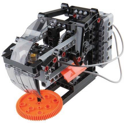
Blenders are not just used in kitchens. Some are used for mixing concrete, and others are used for scientific e peri ents he ost co on kinds are found in kitchens especially used for uice eggs and our Application
Daily
There are various types of blenders on the market. What are the di erences etween the Stirring, mixing, and blending are all things we do in the kitchen when we make dinner. Sometimes, when we mix two or more things together it can be tiring, especially dough for making bread or cakes; so, for some things we use a blender. When we mix ingredients, a "centrifugal force" is generated in the mixing process. The centrifugal force is strong enough to mix all the bits together, especially when there is a blade at the bottom to cut things up.
Centrifugal Force Scientific Application
Juicers are one of the most common types of blenders we will see. These tend to be high-speed, centrifugal force devices.
Blender
8
They use a knife and net to spin and smash fruit at high speeds. The juice goes into a juice cup, and the pulp (fruit residue) is stored in a refuse bucket.
Another common type of juice machine is the low-speed squeezing juicer, which uses an internal screw to twist and compress the fruit at lower speeds. Again, the juice flows out through a filter into a cup, and the pulp is stored until it can be emptied.
37 Brainstorming
Most blenders are composed of a motor, a reduction drive, a stirring shaft and a paddle. It has to use gears to change between speed and power depending on what it is needed for. The shaft with the blades spins in the mixing tank chopping bits up, and the spinning also mixes the ingredients together. Using a mechanical lender can sa e a lot of ti e and e ort


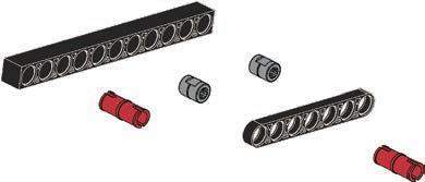
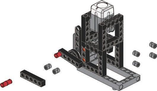
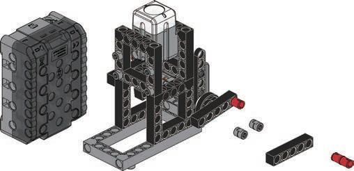
38 Parts List x12 1 x2 31 x3 10 x2 61 x2 38 x1 14 x2 16 x1 20 x1 15 x1 65 x3 2 x2 12 x2 23 x1 26 x1 25 x1 33 x1 46 x2 47 5 4 6 123 11 10 9 7 8


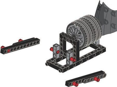
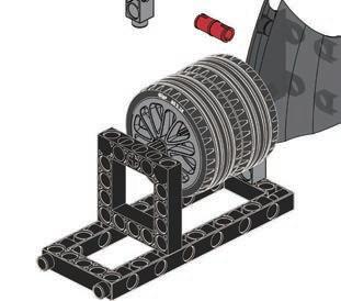
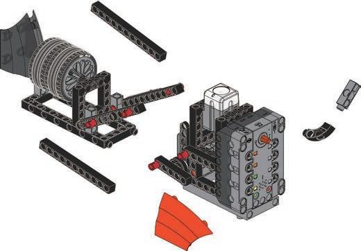
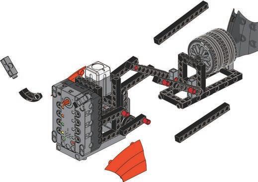
Done Program Example 12 70mm70mm 39 8 Blender OperationModelVideo motor B motor A motormotorAB motor A motor B


1 2 3 40 Smart Manual Web Service ExperimentHands-on CreativityHands-on Evaluation AssembledModel ExperimentComplete CreationModel Fill a cup with some shredded pieces of paper and observe how the paper pieces move when they are stirred. esign a container with other locks that will fit the blender from this lesson.
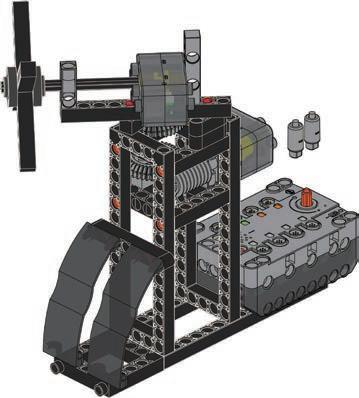
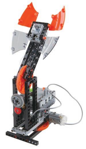
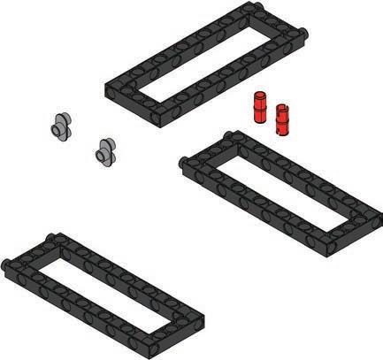
Floor drills can be used to accurately drill holes in arious etals here are di erent types of oor drills with di erent functions depending on si e depth, quantity, and material being used. During use, the object being drilled is placed in a specific area, and the rig is aligned with the center of drilling hole. As the powerful motor spins, it can produce a lot of torque. The object being drilled needs to e held in place with a race or cla p so it doesn t y o arger and more complex drill rigs can be used for drilling blind holes, through holes, or for reaming, which is making an existing hole bigger. Floor drills are important in machinery manufacturing and many industrial situations.
9
Electric drills are used on construction sites, for decoration and renovation, and in the achining industry hey can e used for drilling and screwing oor drill is larger and ore powerful than an electric drill. Floor drills are mainly used for drilling holes in harder metals.
Floor drills are also used to fix objects securely to a surface as they can screw in bolts very tightly. The drill bit rotates vertically downward.
Floor Drill
41 Brainstorming
Daily Application
ow do oor drills help people uild and aintain things Have you ever seen an electric drill? For most people, the answer is usually "yes". But have you seen a oor drill loor drills are uch less co on in daily life What is a oor drill oor drill is si ilar to an electric drill ut it is fi ed in place and points down. Electric drills can be carried around fairly easily ut oor drills are large ounted de ices and cannot be easily moved. In the 19th century, Austrians invented electric drills, combining electric motors with powerful gearing and drill bits. By the end of the 19th century, Australians had invented the first portable electric drills. In the early twentieth century, Germany invented more advanced and user friendly electric drills with handles and triggers, which are the type we often see today.
Rotary Motion Scientific Application


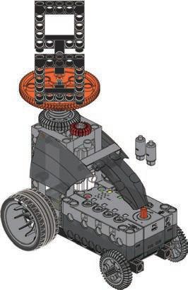
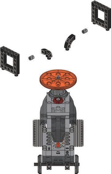
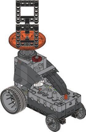
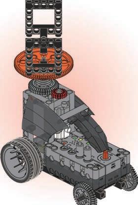
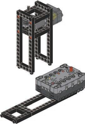
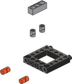
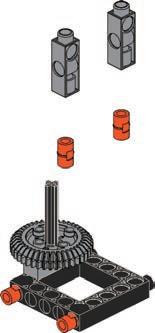
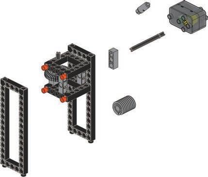
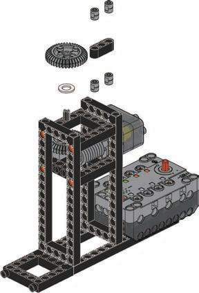
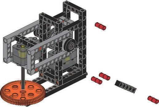
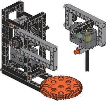
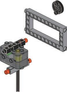
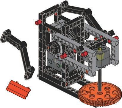
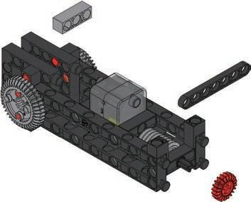
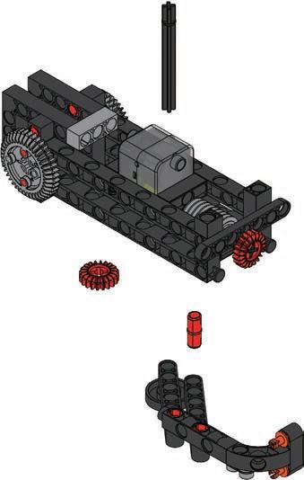
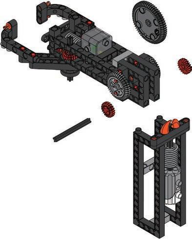
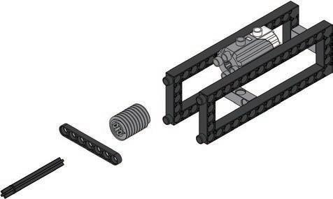
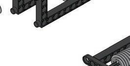
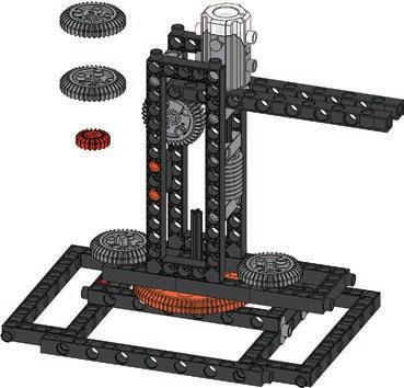
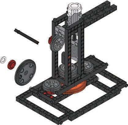
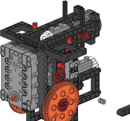
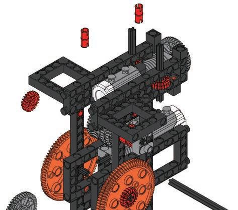
42 Parts List 3 4 12 100mm 70mmx2 13 x10 1 x2 31 x1 32 x1 10 x2 47 x2 63 x2 60 x1 36 x1 37 x2 38 x4 14 x1 15 x1 16 x1 17 x2 18 x1 48 x1 49 x1 65 x15 2 x10 3 x3 6 x2 7 x2 12 x3 23 x2 24 x1 27 x2 26 x1 34 x1 46 x2 45 5 6


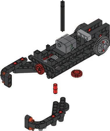
43 9 Floor Drill 13 12 1011 79 8 70mm 2 or 4 1 or 3 2 or 4 2 or 4 1 or 3 1 or 3


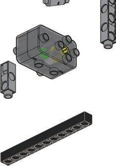
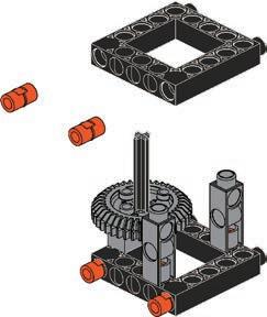
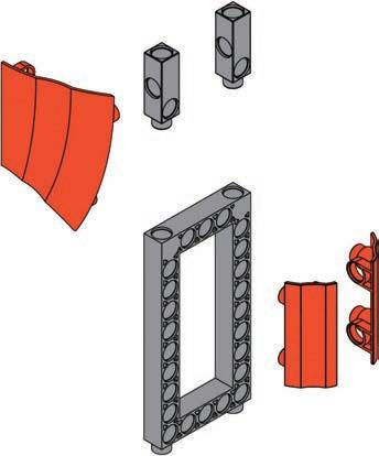
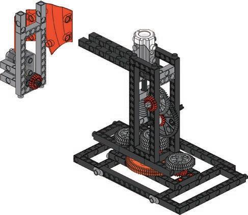
44 14 15 16 17 18 19 20


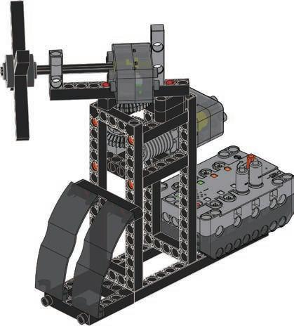
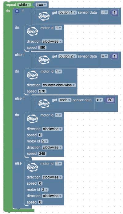
force sensor B force sensor A force sensor A force sensor B 45 9 Floor Drill Done Program Example motormotorB B motor A motor A motor A motor A motor B motor B OperationModelVideo


1 2 3 46 Smart Manual Web Service ExperimentHands-on CreativityHands-on Evaluation AssembledModel ExperimentComplete CreationModel Use the control knob and the FORCE SENSOR to control the oor drill odify the odel and turn the oor drill into a hand-held electric drill.
47 ReviewModel 6.8.HelicopterBlender 7. Electric Fan 9. Floor Drill Use the models and principles you’ve learned to design a spinning clothes dryer. 10 Monograph 2


2 31 48 ConceptDesign CreationModel Winner!DesignModel My Artwork Evaluation
The robot in this lesson has a special sensor, and when it is pressed, the steering program will be activated. This will tell the robot that something is in the way, and the robot will turn to a new direction. This touchcontrolled robot has two sensors, so that it has an idea of which direction to turn.
Remember!
Where else are press sensors or touch sensors used?
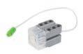
The press sensor (FORCE SENSOR) must be installed at the furthest forward point of the device. It won’t do its job if you install it on top of its head, or on its back! The robot must be able to sense things in time to make a decision about movement.
11
49 Brainstorming
Daily Application Contact DetectionPressureScientific ApplicationRobotTouch-Controlled
Nowadays, many stores have a button on their automatic doors. The door opens automatically when the button is pressed. This is a touch-controlled automatic door. The button contains a press sensor that sends a signal to the door motors when it is pressed. After the receiver receives a signal from the doors, it will instruct the doors to open.
Have you ever noticed any safety functions in an elevator? What happens when the door closes but someone is in the way? here is a u er hidden within the doors and the doors will open again until the doors can close safely. This is how elevators use contact pressure detection.


50 Parts List x5 13 x30 1 x2 10 x1 14 x2 18 x3 21 x4 6 x5 12 x3 23 x1 26 x2 28 x2 31 x2 34 x2 39 x2 40 x1 43 x1 44 x1 47 x2 51 x1 56 x1 59 x2 61 x2 63 x1 65 x2 33 2 70mm A B 1 3×2 ×2 5 6 4 A 7 8 28


Done Program Example 9 10 A A FFULTRASONICSENSORORCESENSORORCESENSOR 51 11 Touch-Controlled Robot OperationModelVideo B


1 2 3 52 Smart Manual Web Service ExperimentHands-on CreativityHands-on Evaluation AssembledModel ExperimentComplete CreationModel Direct the touch-controlled robot towards a flat wall and observe how it reacts. Now, place some obstacles in the robot’s path and let it find its own way forward
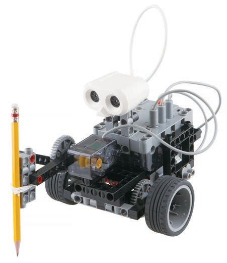
Why is it difficult for a human hand to draw a perfectly straight line? Let’s do a little experiment. Draw two straight lines on a piece of paper, for one, use a ruler, for the other draw freehand. What do you notice about the two lines? Which is straighter? Why? Which would you prefer if you were trying to design a mechanical Todaydevice?we’ll make a drawing robot. Drawing robots can overcome some of the problems that humans have while drawing. Because of the structure of muscles and bones in the hand, it is ery di cult to draw an e actly straight line rawing ro ots can sol e this problem, they use regular mechanical systems to minimize or reduce errors, and draw lines accurately.
53 Brainstorming
Scientific Application
Drawing robots are now becoming more and more advanced. Modern devices can output everything from simple images, to integrating artificial intelligence technology s long as the progra is set correctly, the drawing robot will start work on a project, and not stop until it is finished. As computer science matures, drawing robots are being used for other things like animated movie scripts. In the future, robots may be able to respond to human voice instructions. A user could say the name of an object, like “cat” or “chair” and the device would be a le to sketch the i age his shows the potential of artificial intelligence
12 Daily Application Drawing Robot Mechanical
Now let’s get on with making our own drawing assistant! System


54 Parts List x5 13 x24 1 x2 3 x1 5 x2 10 x2 14 x1 18 x2 16 x4 21 x4 6 x5 12 x3 23 x1 26 x2 31 x3 28 x3 34 x2 39 x2 40 x1 56 x2 51 x1 59 x2 61 x1 65 x1 60 x2 33 2 1 A B 3 ×2 ×2 70mm 28


55 Drawing Robot12 5 6 7 4


56 11 A C 8 9 10 holeB 28


57 Drawing Robot12 Done Program Example A OperationModelVideo ULTRASONICSENSOR


1 2 3 58 Smart Manual Web Service ExperimentHands-on CreativityHands-on Evaluation AssembledModel ExperimentComplete CreationModel Try to draw a straight line with the drawing robot. Modify the programming to make the drawing robot draw an arc. You can also add a change to the speed of the motor.
The light detector in this chapter is able to sense light sources and measure the intensity. If you build it right, it should be able to follow a light source that shines on it. Let’s get started! Daily Application
59 Brainstorming
Light Tracker
Scientific
Which human organ is similar to a light sensor?
13
So what do you know about Green Energy? Do you know which is the ost e cient r when it is the best time of day to collect solar power? It turns out that solar power is currently the most efficient means of collecting renewable energy. There is no “best time of day” for collecting the Sun’s energy, but when the Sun’s rays are perpendicular to the solar panel, they do produce more power. The bad news is that the Earth is spinning and moving all the time, so the position of the Sun, relative to the Earth, is also always changing. Is there a way we can keep solar panels mostly perpendicular to the Sun? Well, someone thought of a solution for that! The “Sun-tracking system” was invented to keep the solar panel oriented perpendicular to the Sun, and move the panel to maximize energy absorption.
Positive PhototaxisApplication
It’s not just machines with light tracking sensors that can follow a light source. Some animals and even plants can follow the Sun. “Phototaxis” refers to the movement of living creatures in response to light. There are two types of phototaxis, one is positive phototaxis and the other is negative phototaxis. A creature with positive phototaxis will instinctively approach a light source, and a creature with negative phototaxis will avoid light as much as possible. Plants, on the other hand, have phototropism. This is where they grow towards a light source co on e a ple of this is the sun ower which turns toward the Sun as it grows. The phototropism of plants also makes branches and leaves grow in the direction of sunlight, in order to absorb the most sunlight for photosynthesis.


60 Parts List x12 1 x2 31 x2 10 x1 44 x1 62 x1 61 x1 60 x2 36 x2 37 x1 41 x2 14 x2 16 x1 18 x2 21 x1 51 x1 65 x19 2 x4 6 x6 12 x3 23 x1 24 x2 25 x3 27 x2 28 x1 29 x1 30 x1 34 x3 33 x1 43 x1 42 3 4 5 6 2 1 35mm 65mm A B 12 11 9 10 7 8 28


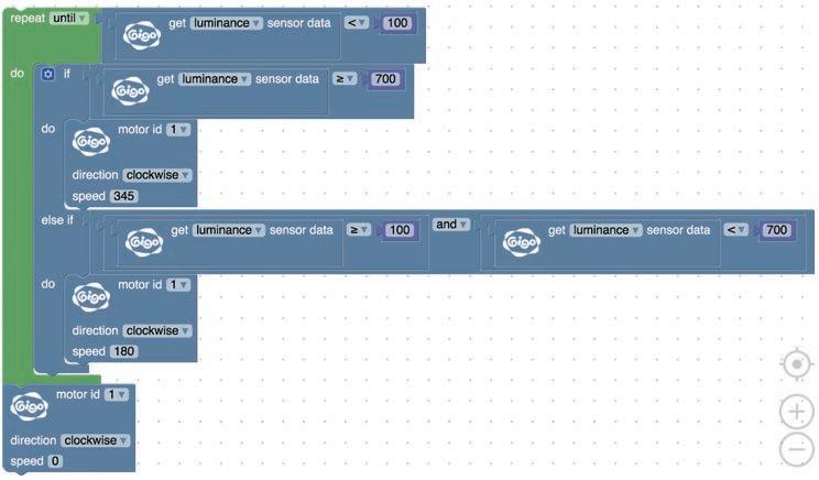
61 13 Light Tracker Done A Program Example 15 17 18 14 16 70mm70mm A 13 ILLUMINANCESENSOR OperationModelVideo 28


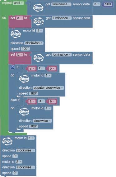
1 2 3 62 Smart Manual Web Service ExperimentHands-on CreativityHands-on Evaluation AssembledModel ExperimentComplete CreationModel Turn off the light and leave only one light on (or shine a bright flashlight) and see how the light tracker moves. Write a program to make the light tracker play a sound when it detects a brightness level over 900 units.
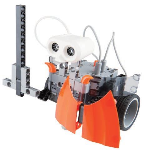
Have you seen a caterpillar? What do they look like, and how do they move?
14
Negative phototaxis is where animals do their best to avoid light. These creatures can be big or small. For example, earthworms, snails, and nematodes, avoid the light as much as possible by hiding in leaves, shelters, or by burrowing into soil. For this lesson, we will simulate the behavior of a caterpillar that is trying to run away from a bright light. Caterpillars have a very unique way of moving and it is fun to watch. Application
Daily
Negative Phototaxis Scientific Application
When the light in the room is dimmed, the pupils of the eyes dilate (get bigger). At this time, if the screen brightness of an electronic product is too high, the eyes will feel uncomfortable. The invention of the "ambient light sensor" is there to help protect the eyes. The ambient light sensor is commonly used in electronic products, such as televisions, computers, tablets, and mobile phones. These electronic products will automatically adjust the screen brightness for human comfort and safety. It also helps save energy too!
63 Brainstorming
As we learned in the last chapter, many plants and animals have a kind of phototaxis. Last lesson was positive phototaxis, which is where the animal likes light. Now let’s look at an example where an animal doesn’t like light, which is "negative phototaxis" (or sometimes photophobia).
CaterpillarLight-Avoiding


64 Parts List 3 3 2 4 6 100mm x18 1 x2 38 x2 39 x2 40 x1 41 x1 42 x1 43 x1 44 x2 51 x1 60 x1 62 x1 65 x4 14 x1 16 x4 19 x6 21 x2 2 x10 3 x2 9 x6 12 x5 23 x1 24 x1 32 x2 28 x1 26 1 5 ×2 ×2 42 41


65 Light-Avoiding Caterpillar14 7 9 11 12 10 8 28 28


66 13 14 15 16 17 motor A motor A SensorIlluminance SensorIlluminance SensorIlluminance


67 Light-Avoiding Caterpillar14 Done Program Example OperationModelVideo


1 2 3 68 Smart Manual Web Service ExperimentHands-on CreativityHands-on Evaluation AssembledModel ExperimentComplete CreationModel Hold down the tail of the caterpillar in different ways and see if you can make it move faster. Change the program to control the caterpillar by sound input. Replace the light-detection function with a sound-detection function.
69 ReviewModel 11. Touch-Controlled Robot 13. Light Tracker 12. Drawing Robot 14. Light-Avoiding Caterpillar Use the models and principles you’ve learned to design a solar-powered swinging sign using a illuminance sensor. 15 Monograph 3


2 31 70 ConceptDesign CreationModel Winner!DesignModel My Artwork Evaluation
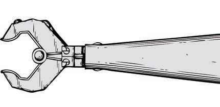
What are the si ilarities and di erences etween a ro otic claw and the claw machines?
71 Brainstorming
Isn’t it awesome to know how powerful robotic claws work? Now, let’s make our own!
Have you ever played a claw machine in the arcades when you can win toys? The principle of these claw machines is similar to the robotic claw we just described. There is a circuit control board in the machine. The claw force is set by the internal voltage. Each claw machine will have a guaranteed amount of grip. When a coin is inserted and the item is not captured, the amount of grip is at the highest level, as the power drops, the grip releases. Are you good at the claw machine games?
Do you know the secret of creating a powerful robotic claw? How do you stop a robotic claw from dropping something it is holding? How can you gradually generate changes in grip? The secret key is the “worm drive”. When a worm gear is driven by a motor, the gear drives a set of clamping arms. At this time, the two gears are moving in opposite directions, and the speed is slow, but the torque increases and is very powerful. Rotation of the worm gear is unique, it only goes one way. That is, the motor can turn the gear, which moves the claws, but the claws cannot be pushed open to turn the gear or motor. This means the grip can be very tight and accurate, and even if the power cuts out, the grip does not change! How clever!
Scientific Application
16
Daily Application
Robotic Claw Worm Drive


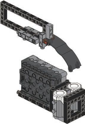
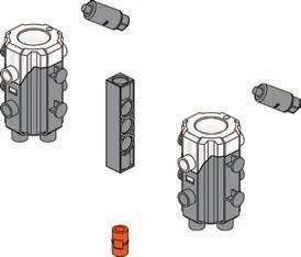
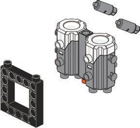
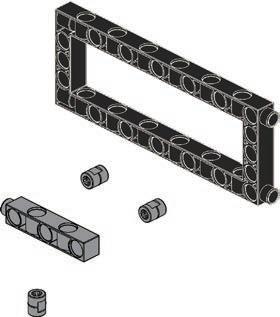
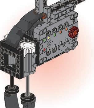
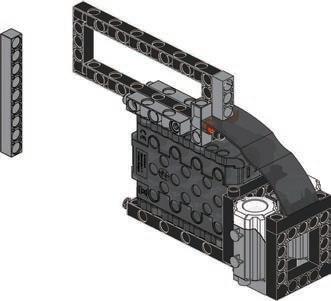
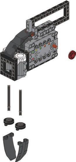
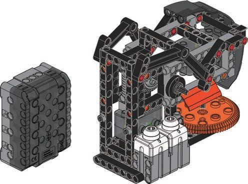
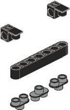
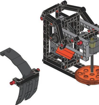
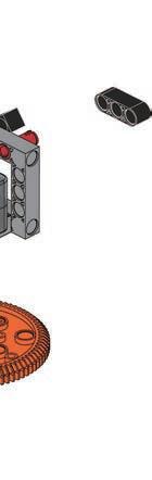
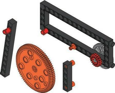
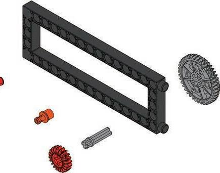
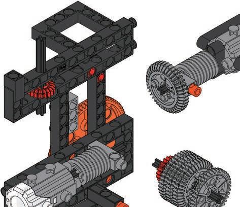
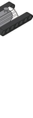
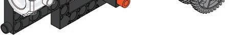
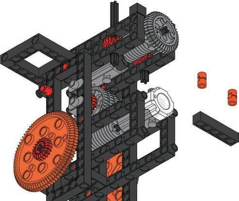
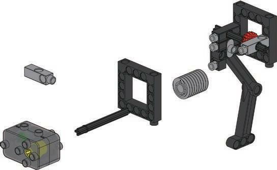
72 Parts List x34 1 x8 31 x3 10 x2 9 x1 44 x2 45 x2 61 x2 60 x1 36 x4 37 x6 14 x4 13 x2 16 x2 17 x5 18 x4 19 x1 20 x7 21 x2 46 x1 56 x1 65 x22 2 x7 3 x3 4 x6 6 x8 12 x5 11 x6 23 x1 24 x1 25 x1 26 x3 29 x4 34 x7 33 x1 43 x2 39 x2 40 x3 38 x1 63 3 4 5 6 1 2 70mm 70mm 70mm 70mm ×2 x2 50 x1 58


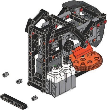
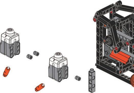
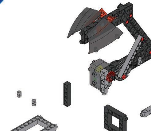
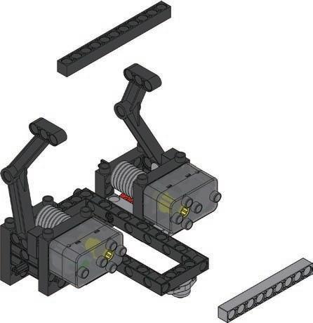
73 16 Robotic Claw A 7 8 9 10 11 12 13


74 14 15 16 17 18 19 20 70mm 35mm 70mm


75 16 Robotic Claw D 21 22 23 24 25 26 27 28 70mm


76 29 30 31 35mm 35mm 32 33 34 35 36 37 70mm


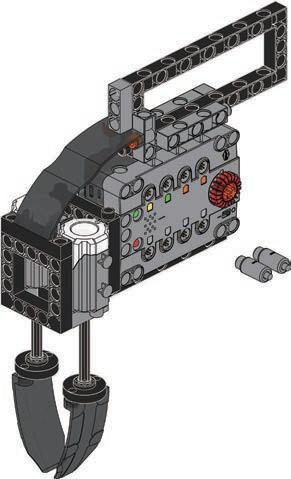
Done Program Example 38 D A FORCE SENSOR 77 16 Robotic Claw OperationModelVideo


1 2 3 78 Smart Manual Web Service ExperimentHands-on CreativityHands-on Evaluation AssembledModel ExperimentComplete CreationModel Try to grip various items (such as an eraser, pencil, or pencil case) with the robotic claw. Try to modify the structure of the robotic claw to grip ite s ore e ciently
79 Brainstorming
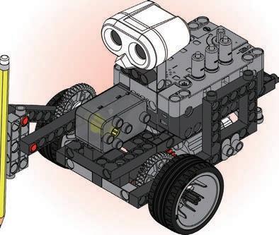
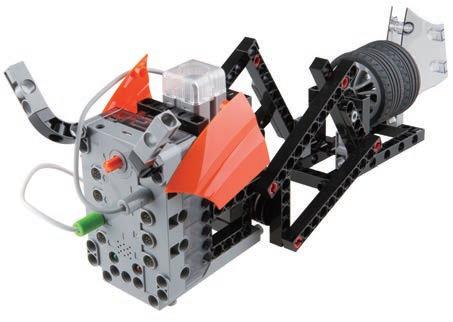
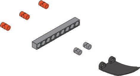
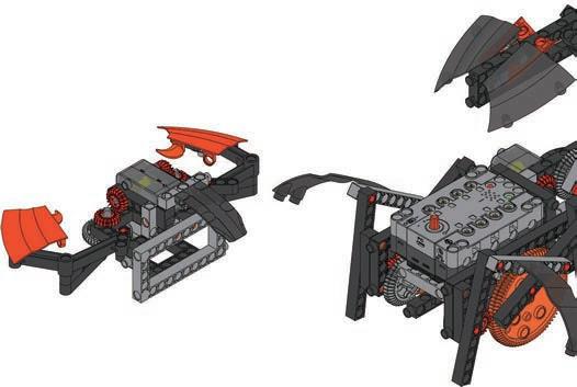
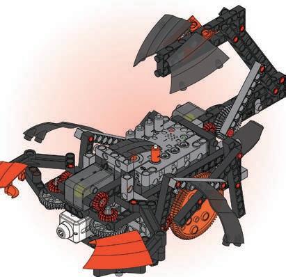
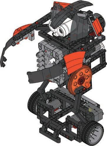
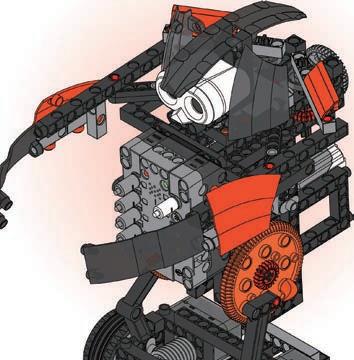
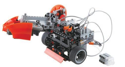
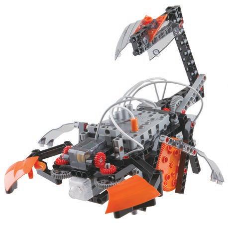
RobotScorpion
When humans design robots, sometimes engineers draw inspiration from observing nature. The "Scorpion Robot" in this lesson is designed to imitate the shape and movement of a scorpion. The tip of the scorpion's tail has a hooked stinger. A scorpion’s sting is delivered by the stinger in a scorpion's tail. When a scorpion stings, its stinger can release venom. The venom contains a mix of toxins that affect the nervous system (neurotoxins). If a small animal is stabbed by its stinger, it will soon die. Besides being a good way to attack other creatures, the tail also acts as a kind of balance for when the scorpion moves.
Linkage Mechanism Scientific Application
Where else in life do you find linkage echanis s
What is a linkage? First we have to understand some other terms such as "linkage group" and "linkage mechanism". A linkage is a mechanism that transmits power and generates restraint. A "linkage group" is composed of multiple linkages. A "linkage mechanism" is a device that manages forces and movement. In simple terms, a linkage mechanism is a device used to transfer mechanical energy. Through careful design and calculation, a linkage mechanism can create both simple and complex movements such as linear movement, reciprocating motions, and rotations.
The coolest part of this scorpion robot is the tail. The linkage mechanism makes the scorpion robot have a lifelike powerful tail. It seems that this scorpion robot may attack at any time, which makes it fun to play with!
Linkages are widely used in machines, such as the left to right swing of an electric fan, the balance of a scale, the steering of a car, the landing gear of an airplane, or the movement of old-fashioned train wheels.
17
Daily Application


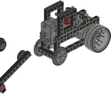
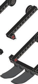
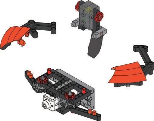
80 Parts List x29 1 x3 10 x2 9 x2 8 x1 44 x2 45 x2 61 x1 63 x2 60 x2 36 x1 41 x1 42 x3 14 x6 13 x3 16 x5 18 x4 20 x7 21 x3 22 x2 46 x2 47 x2 50 x1 48 x1 49 x1 65 x17 2 x21 3 x3 4 x5 6 x3 5 x7 12 x4 23 x2 24 x2 25 x2 27 x3 29 x6 28 x5 34 x9 33 x1 43 3 4 2 1 holeC 5 35mmB


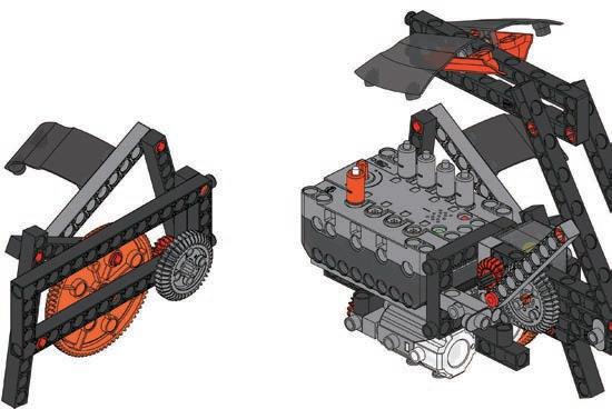
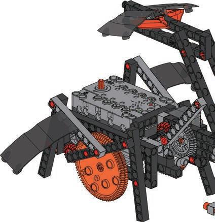
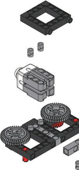
81 Scorpion Robot17 13 12 11 9 10 ×2 ×2 7 ×2 C D D 8 6 C 28 35mm


82 14 15 ×2 ×2 17 16 18 19 ×2 20 21 22 23 28


83 Scorpion Robot17 24 25 26 27 28 30 29 Force Sensor 28 28


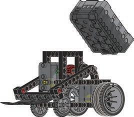
84 31 ×2 holeA holeA 32 33 Please note that the part number is on the inside 34 35 A Please note that the part number is on the inside 36 28 28


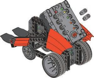
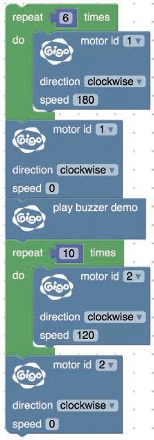
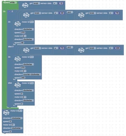
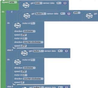
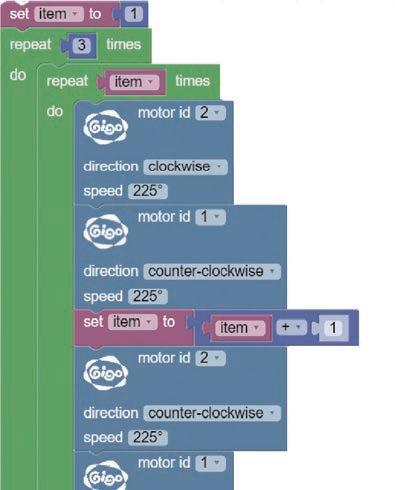
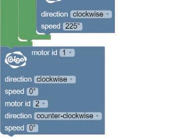
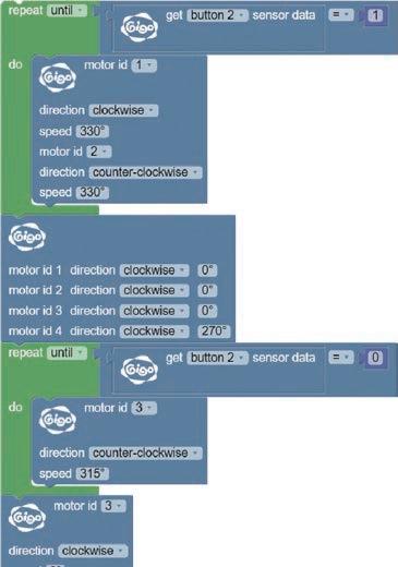
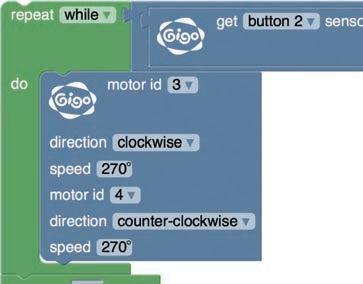
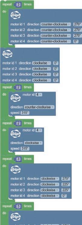
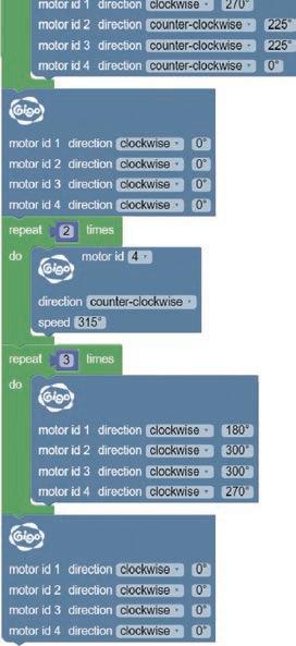
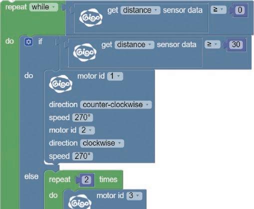
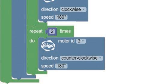
85 Scorpion Robot17 OperationModelVideo Done D A D A D A D A Program Example 37 38 FORCE SENSOR T h e f i r s t p a r t o f t h e p r o g r a m i s a l o o p w h i c h r e p e a t s a s l o n g a s t h e t o u c h s e n s o r h a s n o t b e e n a c t i v a t e d . T h i s b l o c k o f c o d e m o v e s t h e s c o r p i o n r o b o t f o r w a r d S e t t o 3 – 5 t i m e s . W h e n t h e t o u c h s e n s o r i s a c t i v a t e d , m o t o r s 1 a n d 2 a r e t u r n e d o n , m o v i n g t h e c l a w s a n d t a i l . A t t h e s a m e t i m e , m o t o r s 3 a n d 4 a r e t u r n e d o f f .


1 2 3 86 Smart Manual Web Service ExperimentHands-on CreativityHands-on Evaluation AssembledModel ExperimentComplete CreationModel Try to make the scorpion robot move its claws and tail. Modify the program parameters to change the attack speed of the scorpion robot's tail.
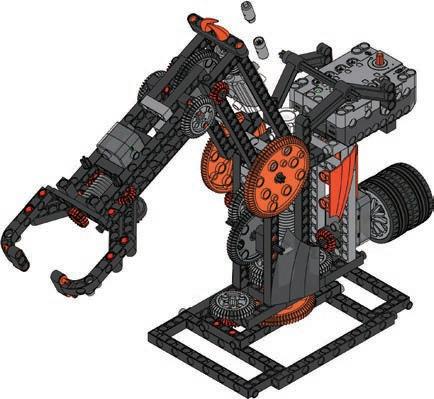
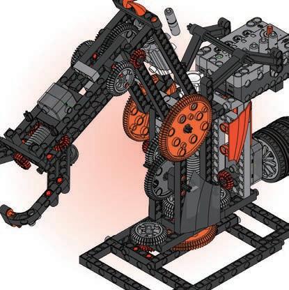
Daily Application
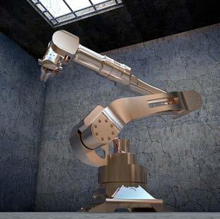
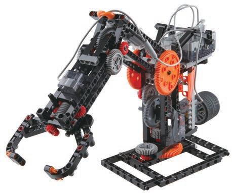
What are the advantages and disadvantages of robotic arms and human arms? We already looked at the robotic claw, but have you ever seen a robotic arm? Robotic arms are widely used in industrial automation. Robotic arms can move up and down, open and close their claws to grab objects and rotate. Robotic arms are highly versatile, and can perform movements accurately and quickly, they are often superior to humans for repetitive work. This makes them ideal for factory production lines. The robotic arm in this lesson is as a “walking motion” type. It is able to rotate 360 degrees. Can your arms rotate 360 degrees? The clockwise and counterclockwise rotation of the motor at the joint can be used to adjust the height of the claw. Cool! Let's get building and make our own!
87 Brainstorming
18
Robotic
Arm Automation Scientific Application
Some robotic arms are used to keep production costs down. They are expensive to buy, but after that, they are cheaper than employing people. In other cases, they are used where people cannot work because the environment is dangerous or harmful to humans. The precision and durability of a robotic arm can reduce many problems. The first e er ro otic ar was used in die casting operations for an erican auto o ile co pany ow they are used in any di erent industries and for a variety of reasons. They can be found in factories that produce cars, electronics, medical equipment and even farming tools.


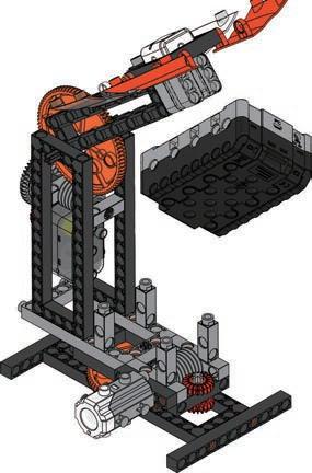
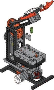
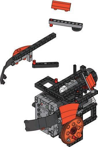
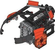
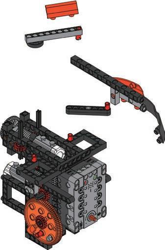
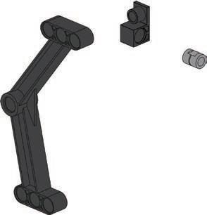
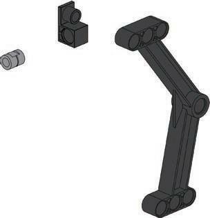
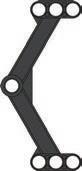
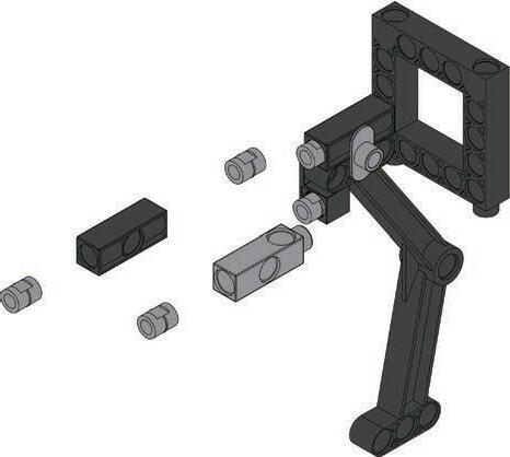
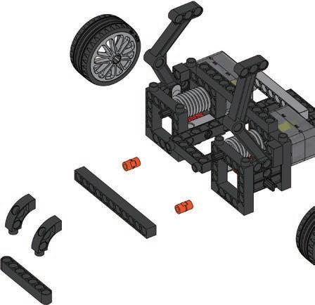
88 Parts List x35 1 x3 10 x2 9 x2 8 x2 7 x9 31 x1 32 x3 36 x3 37 x2 38 x2 39 x2 35 x3 14 x5 13 x2 17 x5 18 x3 19 x1 21 x3 22 x11 33 x7 34 x2 40 x1 41 x1 42 x1 43 x18 2 x13 3 x4 4 x8 6 x4 5 x10 12 x5 11 x5 23 x2 24 x2 25 x4 27 x3 26 x1 29 x1 30 x3 28 x1 44 x2 45 x1 48 x1 49 x2 50 x2 51 x1 52 x1 58 x2 60 x2 61 x1 64 x1 65 A 1 4 5 6 7 8 9 3 70mm


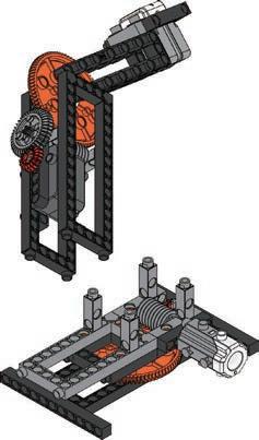
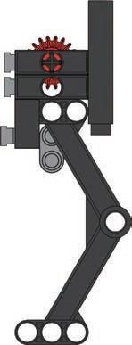
89 18 Robotic Arm 10 11 12 13 14 15 16 17 ×2 70mm 70mm holeB


90 18 19 20 21 23 22 70mm 70mm 65mm 24 25 70mm 28 28


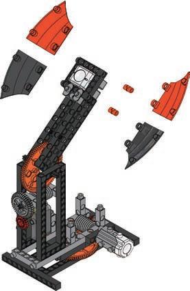
91 18 Robotic Arm D 26 27 28 29 30 31 32 33 34 70mm 35mm 28


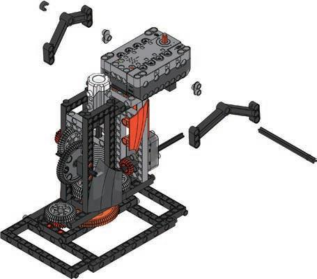
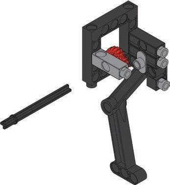
92 70mm 35 36 37 38 39 100mm Please note that the part number is on the Pleaseinside.note that the part number is on the inside. 40 41 42 70mm×2 6 6 52


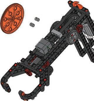
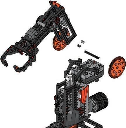


93 18 Robotic Arm OperationModelVideo Done D A D A Program Example 43 Extension cord


1 2 3 94 Smart Manual Web Service ExperimentHands-on CreativityHands-on Evaluation AssembledModel ExperimentComplete CreationModel Place objects (such as erasers, pencils, and pencil cases) around the robotic arm and try to pick them up and move them. Add a pressure sensor (force sensor) and modify the program to control the robotic arm with the pressure sensor and input knob.
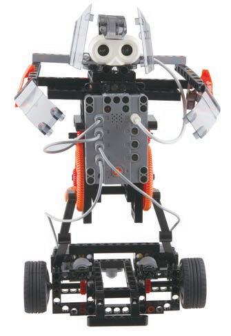
Why do humans develop humanoid robots? What do you call a robot that resembles a human? Dave? John? Emma? No, they are androids! An android is a robot that mimics human appearance, and sometimes human behavior. Some roboticists (robot scientists) hope humans and robots will be able to live and work together peacefully. To do that, robots need to be programmed very carefully, so that they have a good attitude. The purpose of humanoid robotics is to explore the interactions, cognitions and emotions that hu ans ha e and how they in uence ro ots This lesson will show you how to make a humanoid robot. When the robot senses that an object is very close, it will close its arms and grasp the object. Furthermore, it is a polite robot. When it sees people, it will take a step back and bow. Isn't it cute? Let's get started!
Daily Application
rtificial ntelligence Scientific Application
Artificial Intelligence (AI) is the name for technology that presents human intelligence through computer programming. AI first appeared as an idea around 1950. At that time, AI was only implemented by written logic statements. Today, AI not only simulates human wisdom but also develops reasoning ability, decision-making and learning, such as speech recognition. What are some online AI assistants that you know of? Many popular AI bots are used for chat, customer service, face recognition and medical assistance.
95 Brainstorming
19
RobotHumanoid


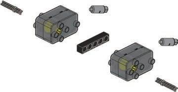
96 Parts List x28 1 x2 10 x2 9 x2 8 x2 7 x9 31 x1 32 x2 36 x4 37 x2 38 x2 39 x5 14 x2 13 x2 17 x5 18 x5 19 x4 20 x2 21 x2 22 x10 33 x6 34 x2 40 x1 41 x1 42 x1 43 x22 2 x12 3 x12 6 x12 12 x5 11 x6 23 x2 25 x2 27 x3 26 x2 29 x1 44 x2 45 x1 48 x1 49 x2 50 x2 46 x2 47 x1 59 x1 56 x2 60 x2 61 x1 65 70mm 5 Ultrasonic Sensor×2 3 4 2 1


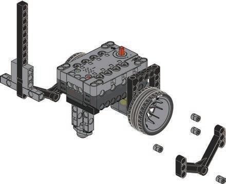
97 19 Humanoid Robot A 7 8 9 11 10 6 35mm 70mm 70mm 70mm A B


98 15 13 14 16 12 70mm 35mm 17


99 19 Humanoid Robot 18 19 20 21 22 23 70mm 100mm


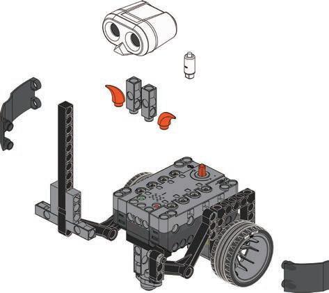
100 24 25 26 27 ×2 28 29 30


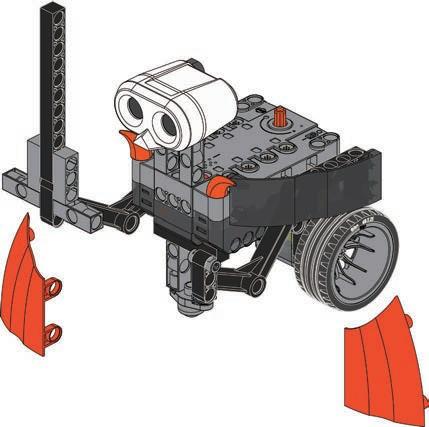
10119 Humanoid Robot 31 32 33 34 35 Please note that the part number is on the inside. 70mm 70mm C Please note that the part number is on the inside. 36 37


102 D C 38 39 40 70mm 70mm 41 42 43 D D ×2


DoneProgram Example A D A D 44 ULTRASONICSENSOR10319 Humanoid Robot OperationModelVideo


1 2 3 104 Smart Manual Web Service ExperimentHands-on CreativityHands-on Evaluation AssembledModel ExperimentComplete CreationModel Place a book in front of the humanoid robot and observe how it behaves. Write a program to extend the functionality of your robot.
105 ReviewModel 16. Robotic Claw 18. Robotic Arm 17. Scorpion Robot 19. Humanoid Robot Use the models and principles you’ve learned to design a robot that can throw a ball. 20 Monograph 4


2 31 106 ConceptDesign CreationModel Winner!DesignModel My Artwork Evaluation
MADE IN TAIWAN © 2021 Genius Toy Taiwan Co., Ltd. ALL RIGHTS RESERVED R21#1203-1