HONDA EU1000i
GENERATOR
HONDA EU1000i Generator
Generator Model
Rated (Surge) Watts
Output Volts
DC Amps
Engine Model
EU1000i
900 (1000)
120 AC/12 DC
8
GXH50-GCAL
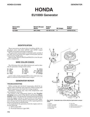
IDENTIFICATION These generators are direct drive, brushless, 60 Hz, single-phase units with both 120VAC and 12VDC output available from panel-mounted receptacles. The generator serial number is located on the outside of the side cover, just below the engine switch knob and the recoil starter handle grip. Refer to Figs. HA151, HA152 and HA153 to view the generator components.
WIRE COLOR CODES The following color-code abbreviations are used to identify the generator wiring in this series: Bl – Black R – Red Y – Yellow Gr – Gray
Bu – Blue G – Green Br – Brown P – Pink
W – White Lb – Light blue Lg – Light green O – Orange
A wire with a slash-separated ID is a two-color wire; (e.g. R/W is a red wire with a white tracer stripe).
GENERATOR REPAIR TROUBLESHOOTING Before testing any electrical components, check the integrity of the terminals and connectors. While testing individual components, also check the wiring integrity. Resistance readings may vary with temperature and test equipment accuracy. For access to the components listed in this Troubleshooting section, refer to Fig. HA151 and the later Disassembly section. All operational testing must be performed with the engine running at its governed no-load speed of 5400-5600 RPM, unless specific instructions state otherwise. Always load test the generator after repairing defects discovered during troubleshooting. 1. To troubleshoot the generator, start the engine and verify the following: a. ECO switch OFF, b. Overload Indicator Light OFF,
172
Fig. HA151 – Exploded view of the electrical generation components. 1. Engine 2. Stator assembly 3. Rotor assembly 4. Rotor flange nut 5. Cooling fan
6. 7. 8. 9.
Fan boss Starter pulley Ignition pulse generator Fan housing stud (3)
SERVICE MANUAL
HONDA EU1000i c. If the AC pilot light is ON, stop the generator, perform Step 2 then proceed to Step 3. If the pilot light is OFF, stop the generator, perform Step 2 then proceed to Step 4. d. DC circuit breaker button IN (circuit breaker will be covered in Step 5). 2. Remove the four front panel cover screws, then remove the cover and panel. 3. To test the AC receptacle: a. Disconnect either red feed wire by inserting a small flat blade screwdriver into the slot next to the wire, then pulling the wire terminal out (Fig. HA153). b. Install a jumper wire across one pair of terminals. c. The receptacle should now test continuity across the feed terminals. Failure of the receptacle to test continuity indicates a faulty receptacle. d. The receptacle should also test continuity between its mounting flange and the ground terminal. Failure to test ground continuity indicates a faulty receptacle. e. The AC Composite Sockets, or Parallel Operation Terminals, mounted above the AC receptacle on the control panel, can be continuity tested by placing one meter lead inside the socket and one lead on the back terminal. Continuity should be present. Failure to read continuity on either socket indicates a faulty socket.
Fig. HA152 – Removing the AC connections to test the receptacle. 10. Starter harness 11. Inverter unit 12. Rubber mounts
13. Rubber mount 14. Rectifier
Screwdriver
Red
Gray
Blue
Orange White
Fig. HA153 – Accessing the six-pin connector to test AC output. Refer to text for the correct test procedure. 1. Front cover 2. Control panel 3. 120V receptacle
4. 12V receptacle 5. Ignition control module
6. Control panel harness 7. 6-Pin connector
173
HONDA EU1000i 4. To test for AC output: a. Access and identify the six-pin (red, white, blue, orange, gray, and black) inverter-harness connector (Fig. HA153), but do not unplug the connector. b. Start the generator. c. Test the main coil AC voltage between the red-blue, blue-white, and white-red paired terminals (1-2, 2-3, and 3-1). Voltage should be 227-263 volts at each pair. d. Test the sub coil AC voltage between the gray-orange wire terminal pair (4-5). Voltage should be 11-15 volts. e. Stop the generator, then unplug the 6-pin connector. f. Using an ohmmeter and the same three terminal pairs as Step 4c, test the winding resistance. Each winding should test 2.100-3.300 ohms. g. Using an ohmmeter and the same gray-orange terminal pair as Step 4d, test the winding resistance. The winding should test 300-500 ohms. h. Still using an ohmmeter, test for continuity between any good, clean ground position on the engine block and each of the five wire terminals. There should be infinity/no-continuity. i. If one or more of the results of test Steps 4c or 4d failed to meet specification, or if any of the results of test Steps 4f-4h failed to meet specification, the stator windings are faulty. Replace the stator. j. If all of the results of test Steps 4f and 4g tested equally low, the rotor magnetism is weak. Replace the rotor. k. If all of the preceding test results met the specification but there is still no AC output, return to Step 3 and test the AC receptacle. If the receptacle tests good, and the wiring integrity is correct, the inverter is faulty. Replace the inverter. 5. To test for DC output, if none is present at the DC receptacle: a. Access the back of the DC circuit breaker/receptacle and unplug the harness connector, then press the reset button. If the button does not stay in, the receptacle is faulty. If the button stays in: • Place a jumper wire between the receptacle output terminals (Fig. HA154). • Test for continuity between the input terminals. Continuity indicates a good receptacle. • Test for continuity between the input terminal fed by the white/black wire and the vertical output terminal. Continuity indicates a good breaker. b. Access the diode rectifier assembly at the back of the inverter unit (Fig. HA155) and disconnect the harness. Using a VOM set to the R × 1 scale, test continuity between any one pair of adjacent or diagonal terminals (1-2, 1-3, 2-4, 3-4, 1-4, or 2-3). Note the reading. Reverse the meter leads and again note the reading. Repeat the test with the other five terminal pairs. Compare the readings with the chart. Any variation indicates a faulty rectifier. NOTE: Depending on meter polarity, continuity/infinity readings may be exactly opposite those shown in the chart. If so, reverse the positive and negative probe notations in the chart. c. Access the four-pin diode rectifier harness connector:
174
GENERATOR Test the resistance of the two brown-wire terminals in the rectifier connector. Resistance should test 0.1-0.2 ohm. Measure the resistance between each brown wire terminal and any good, clean ground position on the engine block. There should be infinity/no continuity. If the test results met specification, any fault is in the wiring; repair or replace as necessary. If the test results did not meet specification and the wiring integrity is secure, the DC stator winding is faulty. Replace the stator.
Wire Fig. HA154 – Testing the DC breaker/receptacle for continuity by installing a jumper wire across the outlet terminals. Refer to text for the correct test procedure.
(+)Probe (-)Probe
1
1
2
3
4
∞
∞
∞
Continuity
Continuity
2
Continuity
3
Continuity
∞
4
Continuity
∞
∞ ∞
Fig. HA155 – Terminal test positions for the diode rectifier. Refer to text for the correct test procedure.
6. To test the stator exciter-coil winding: a. Access the 2-wire (black/blue and yellow/green) connector behind the control panel. b. Continuity test the wire terminals; resistance should be 0.5-0.9 ohm. c. If test results do not meet specification, proceed to the Disassembly section. 7. To test the ECO throttle control system: a. Access the ECO switch and continuity test the terminals. There should be continuity in the ON position only.
SERVICE MANUAL
HONDA EU1000i
NOTE: The ECO throttle switch should always be installed in the control panel with the ON and OFF markings up. b. Access the throttle control motor mounted on top of the carburetor and test the resistances between terminals 1-3 and terminals 2-4 (Fig. HA156). Resistance should be 50-70 ohms at each noted terminal pair. Resistance readings beyond this range indicate a faulty motor. c. Move the throttle lever and check the ECO motor for smooth operation. If binding is noted, disconnect the throttle linkage to determine the source of the binding. Correct as necessary. d. The ECO switch is faulty if it fails to function as follows: • The no-load engine speed should increase with the ECO switch OFF. • The no-load engine speed should decrease with the ECO switch ON. • The engine speed should increase when a load is applied to the generator with the ECO switch ON. e. To operationally check the ECO motor after replacing the inverter: • While observing the throttle, start the engine, allow it to run briefly, then stop the engine. • At start up, the throttle should move from wide-open to normal run. • At shut down, the throttle should return to the wide-open position.
• If the ECO motor does not perform properly, replace the motor. 8. To test the ignition control module: a. Leave the control panel harness connected to the panel, but disconnect the 10-pin module connector from the module (Fig. HA157). b. Test resistance between the black wire terminal (coil primary circuit) and engine ground. Resistance should be 0.7-1.1 ohms. c. Test for continuity between the yellow wire terminal (oil-level switch) and engine ground. There should be infinity/no continuity with the crankcase oil at the proper level. d. Test resistance between the blue wire terminal (ignition pulse generator) and engine ground. Resistance should be 25-39 ohms. e. Test for continuity between the green wire terminal (ground) and engine ground. There should be continuity. f. Test resistance between the black/blue wire terminal (stator exciter coil) and engine ground. Resistance should be 0.5-0.9 ohm. g. If all the above tests conclude within specification, the ignition control module is faulty. Replace the module. 9. To initially test the oil level switch: a. Insure that the crankcase oil is full and that the generator is sitting level. b. Disconnect the spark plug lead. Connect an approved spark tester to the plug lead and the engine ground. c. Pull the starter rope. If no spark is visible at the tester, proceed to the ENGINE, Ignition System section of this Chapter. d. If there is spark, drain the crankcase oil and pull the starter rope again. If there is spark, proceed to the ENGINE, Ignition System section of this chapter.
Disassembly Not used
Fig. HA156 – Terminal test positions for the ECO throttle control motor. Refer to text for the correct test procedure.
Green
Black/blue
Blue
Yellow Black
Fig. HA157 – View showing the 10-pin connector removed to test the ignition control module. Refer to text for the correct test procedure.
To disassemble the generator: 1. Remove the muffler protective cover, control panel front cover, and side panel maintenance cover. 2. Remove and disconnect the control panel assembly. 3. Carefully drain the fuel tank and the crankcase oil. NOTE: The oil should be drained hot, but generator disassembly should be performed with the unit cool. 4. Unscrew the carburetor bowl drain screw to drain the bowl. Disconnect the bowl drain hose, vent hose, air-intake hose, and throttle control motor harness. Remove the carburetor. 5. Remove the side covers, noting the positions of the internal rubber mounts and insulator collars. Disconnect the fuel valve hose from the bottom of the fuel tank. 6. Remove the fuel tank, noting the position and condition of the tank mounts. The left and right rubber mounts are not interchangeable. 7. Disconnect and remove the inverter unit, noting the position and condition of the inverter mounts. 8. Remove the engine bed mount plate assembly; note the position and condition of the bed mounts and collars, and the position of the wiring harness ground wire. 9. Remove the air filter assembly and tube.
175
HONDA EU1000i
GENERATOR
10. Remove the fan cover assembly, taking care not to lose the collars which fit between the cover and the mount studs. The recoil starter and the ignition coil are mounted to the fan cover. They should not have to be removed unless they are being repaired or replaced. 11. Remove the fan shroud halves, noting the position of the top insulator and collar assembly and the harness clamp. 12. Remove the ignition pulse generator unit. The pulse unit can be tested at this time by measuring resistance between Terminals ‘A’ and ‘B’ of Fig. HA158. The resistance should be 25-39 ohms. 13. Holding the rotor with a strap wrench, remove the starter pulley, cooling fan boss, cooling fan, and rotor nut. NOTE: Do not strike the rotor. Striking the rotor will damage it. 14. Using a 2-slot puller, remove the rotor from the engine crankshaft. 15. With the rotor removed, perform an islation test on the stator exciter coil. a. Test for continuity between the black/blue wire terminal and the stator lamination core. Resistance should be 0.5-0.9 ohm. b. Any test result other than that specified indicates a faulty stator. Replace the stator. c. If the winding passes the preceding Step A test but failed the troubleshooting continuity test, the stator is working but the stator to control panel wiring is faulty. Repair or replace as necessary.
Reassembly To reassemble the generator: 1. Insure that: a. The matching tapers on the engine crankshaft and inside the rotor hub are clean and dry, and the matching engine block shoulder and stator hole are clean. b. There is no metallic foreign material stuck to the rotor magnets. c. The crankshaft woodruff key is properly positioned in its slot. 2. If the stator was removed, install it now and torque the stator mount bolts 5.9 N•m (52 in.-lb.). Make sure that the stator harness is routed correctly. It must be held in place by the ignition pulse generator bracket. 3. Install the rotor. Holding the rotor with a strap wrench, torque the rotor nut 27 N•m (240 in.-lb.). Rotate the rotor by hand to make sure that the rotor does not rub against the stator. Correct any misalignment or interference. 4. Install the cooling fan and fan boss. 5. Position the starter pulley onto the fan boss with the lock tab in one of the V-grooves of the fan boss. Holding the rotor with a strap wrench, install the pulley flat washer and bolt. Torque the bolt 9.8 N•m (85-90 in.-lb.). 6. Install the ignition pulse generator unit, making sure that the pulse unit mounting arm secures the stator harness. The air gap clearance between the rotor projection and Terminal A of the pulse unit (Fig. HA158) should be set at 0.4-0.6 mm (.016-.024 in.). Torque the pulse unit bolts 5.9 N•m (52 in.-lb.). Reconnect the blue pulse unit wire. 7. Verify that the rubber cylinder fin inserts are correctly positioned (Fig. HA159) and the shroud seals are correctly fastened to the shrouds. Apply a 1.0 mm diameter (3/64 in.) bead of Loctite 515 liquid gasket or equivalent to the
176
Fig. HA158 – Resistance between Terminals A and B of the ignition pulse generator should be 25-39 ohms.
crankcase breather tube prior to inserting it into the crankcase (Fig. HA160). Mount the side shrouds to the engine assembly. Note the position of the top collar, insulators, and washers. 8. Mount the positioning collars onto the engine studs, then mount the fan cover assembly onto the engine. Tighten the cover nuts. When installing the ignition coil ground wire terminal onto the lower left stud, make sure that the washer is installed between the fan cover and the terminal. 9. Install the air filter assembly and tube. 10. Install the engine bed mount plate assembly, ensuring proper placement of the insulators, collars, and washers (Fig. HA161). 11. Verify the correct routing of the hoses and tubes on the carburetor side of the engine assembly (Fig. HA162). When installing the tube protector over the fuel pump to carburetor hose, do not allow the long end to cover the 90° bend in the hose (the long end goes toward the pump). 12. Reconnect the inverter unit, then reconnect the wiring harness ground wire to the weldnut on the bottom of the bed mount. 13. Reinstall the fuel tank, verifying the correct positioning of the non-interchangeable rubber tank mounts. The mount with the longer, channel style foot fits on the tank extension next to the fuel hose fitting. 14. Verify the integrity and correct routing of the hoses and wiring inside the left side generator cover (Fig. HA163). 15. Connect the generator harness to the two-pin engine switch plug in the left side cover (Fig. HA163). Secure the wire with the cable tie (Fig. HA164). 16. Laying the left cover down, fit the engine/inverter unit into the mount positions in the cover, verifying the proper placement of the rubber mounts, washers, and collars. Make all hose and wiring connections as necessary. 17. Verify the integrity of the cover seals in the right cover, then place the right cover onto the left cover. Install and tighten the cover fasteners. 18. Stand the generator upright. Install the top snap ring and the gas tank neck seal. 19. Using new gaskets and O-ring, install the carburetor, reconnecting the air filter, fuel, and vent hoses and the throttle control motor harness. Make sure that the straight side of the outer carburetor manifold insulator is UP 20. Connect and install the control panel assembly. 21. Install the side panel maintenance cover, control panel cover, and muffler protective cover.
SERVICE MANUAL
HONDA EU1000i Lubrication
ENGINE The model GXH50 engine is a four-stroke design with push-rod operated overhead valves. The engine serial number is stamped on a flat boss on the lower side of the crankcase, to the left of the oil fill plug. Exploded views of the engine are shown in Figs. HA165A-HA165D. To access the engine, refer to the GENERATOR REPAIR, Disassembly section of this chapter.
MAINTENANCE Spark Plug The recommended spark plug is NGK CR5HSB, Denso U16FSR-UB, or equivalent. Recommended gap is 0.6-0.7 mm (.024-.028 in.). Torque plug 12 N•m (105 in.-lb.). CAUTION: Do not use abrasive blasting to clean spark plugs as this may introduce abrasive material into the engine and cause extensive damage.
The engine is splash lubricated by a dipper on the connecting rod cap. Oil capacity is 0.25 litre (0.26 US qt). The crankcase is full when no more oil can be added to the oil fill hole with the generator sitting level. Use oil with an API service classification of SH, SJ, or better. Use SAE 30 oil if temperatures are consistently above 10° C (50° F), SAE 10W30 in any temperature, or SAE 5W30 if temperatures are consistently below freezing. DO NOT USE 10W40 oil. Drain the old oil when it is hot to insure the removal of all impurities. To drain the oil: 1. Remove the maintenance cover panel. 2. Unscrew the oil fill cap. 3. Tilt the generator. Whenever the crankcase oil has been drained, dry test the operation of the low oil shutdown switch: 1. Insure that the generator is sitting level. 2. Remove the spark plug.
Rubber insert B
Rubber insert C
Exhaust manifold
Rubber insert D
Rubber insert C, D Rubber insert B
Rubber insert B
Rubber insert A
Fig. HA159 – View showing the proper placement of the rubber cylinder fin inserts, inner carburetor insulator assembly, and exhaust manifold.
177
HONDA EU1000i
GENERATOR 10 mm (0.4 in)
Cutout
Fig. HA160 – View showing air shroud placement over engine assembly. Note correct placement and installation of crankcase breather hose and fuel pump pulse hose. 1. Engine assembly 2. Left shroud 3. Right shroud 4. Left shroud seal
5. Right shroud seal 6. Pump diaphragm tube 7. Breather tube 8. Shroud insulator (2)
9. Insulator collar 10. Insulator washer (2) 11. Harness clip bracket 12. Harness clip
3. Connect an approved spark tester to the plug lead and cylinder block. 4. Pull the starter rope and check for spark; there should be none. 5. If the tester shows spark with no oil in the crankcase, the shutdown switch is faulty. Refer to the subsequent Ignition System section for testing and replacement.
Air Filter 1. To access the filter, remove the maintenance cover panel and the snap fit filter cover. 2. Gently clean the sponge filter element in a warm detergent/water solution. Rinse thoroughly, then allow to dry completely. 3. Pour clean engine oil onto the element, squeezing out any excess oil. 4. Reinstall the element. 5. Inspect the snap fit filter cover, insuring that the channel mounted cover seal fits tightly in the cover all the way to the channel ends. Replace if necessary. 6. Reinstall the filter cover, and the maintenance cover panel. Fig. HA161 – View showing proper placement of engine mounts, inverter unit, and diode rectifier case breather hose and fuel pump pulse hose. 1. Engine bed frame 2. Vibration isolators (4) 3. Isolator collars (2) 4. Isolator washers (4) 5. Inverter unit
178
6. Bottom inverter mounts (2) 7. Side inverter mount 8. Rectifier 9. Engine/generator unit 10. Ground wire
Carburetor To access the carburetor, refer to the GENERATOR REPAIR, Disassembly section. 1. If necessary, remove the throttle control motor assembly (Fig. HA166). To test the throttle control motor, refer to the GENERATOR REPAIR, Troubleshooting section.
SERVICE MANUAL Diaphragm tube
HONDA EU1000i
Fuel tube (pump - carburetor
To carburetor Open 20 mm (0.8 in) Tube clamp Engine side
Breather tube
Drain tube Air vent tube Fig. HA162 – View showing proper routing of engine hoses and tubes.
Fuel tube (valve to pump)
Fuel tube (pump to carburetor)
Diaphram tube
Engine switch
Fuel tube (tank to valve)
Fuel Pump
Engine switch wire
Fig. HA163 – View showing fuel system hose routing and engine switch wire routing inside the left side generator cover.
Sub wire harness
Grommet
Engine side
Harness clip
2. Disassemble the carburetor referring to the exploded drawing of Fig. HA167. Clean and renew components as necessary. 3. Inspect the float valve and seat, float pivot arm, float pin, and carb body float pin stanchions for wear. Renew as necessary. 4. The throttle shaft and choke shaft are not serviced separately. If wear exceeds reasonable limits, the carburetor must be replaced. 5. The pilot screw limiter cap prevents removal of the pilot screw without breaking the screw. If carburetor repair requires pilot screw removal and replacement: a. Install the spring onto the screw. b. Lightly seat the screw all the way into the carb. c. Back the screw out 2-5/8 turns. d. Apply Loctite 638 or equivalent inside the limiter cap, then fit the cap to the pilot screw so the cap stop prevents the screw from being rotated counterclockwise. DO NOT turn the screw while installing the cap. 6. The pilot jet must be installed prior to installing the throttle stop screw. Lightly oil the jet O-ring prior to installation. 7. To check float height: a. Set the carburetor vertically on the workbench, manifold flange down and float pin up, so the float is hanging (Fig. HA168). b. Pressing lightly against the float to cause the float valve to contact its seat, measure the distance from the bowl mount flange to the bottom edge of the float on the side of the float opposite the valve. It should be 12.0 mm (0.47 in.). Any other dimension necessitates replacing the float. c. Insure that the float operates freely. 8. Install the float bowl so that the bowl drain screw fitting is on the choke side of the carburetor. 9. Prior to reinstalling the throttle control motor assembly, fit the link lever spring onto the link lever pin. Then position the link lever onto the throttle lever with the spring in its recess. Ensure that the throttle control motor drive pin fits into the link lever slot correctly.
The fuel pump cannot be repaired. If it does not pump, it must be replaced as a unit. To troubleshoot the pump system: 1. Check the integrity of the pre- formed fuel system hoses and the fuel filter in the tank outlet fitting. If any hoses require removal or replacement, refer to Fig. HA162 and verify correct orientation. 2. Remove the pulse hose from the crankcase fitting. While pulling the starter rope, make sure that crankcase pressure/vacuum pulsations pass the fitting. 3. Ensure that the carburetor is not blocked, or otherwise preventing pump operation. Loosen the carb bowl drain screw; while pulling the starter rope, observe fuel flow from the bowl drain hose.
Valve Clearance
Generator wire harness
Ignition coil primary wire
Engine switch wire
Fig. HA164 – View showing correct cable fastening for proper wiring security inside the generator cover.
Checking and adjusting valve clearance must be done while the engine is cold. 1. Remove the valve cover screws. 2. Carefully pry up each corner of the valve cover to loosen and remove the cover. Alternate between the corners while prying. Excessively forcing one corner more than the others will deform the cover; a deformed cover must be replaced.
179
HONDA EU1000i
GENERATOR
Fig. HA165A
Fig. HA165B
Fig. HA165C
Fig. HA165D
Fig. HA165A-D – Exploded view of mechanical engine components. 1. Cylinder block 2. Oil case 3. Oil-level switch and O-ring 4. Crankshaft with cam-drive gear 5. Piston/rings/connecting rod assembly 6. Breather assembly 7. PTO seal 8. Oil cap and gauge 9. Crankcase cover
180
10. Locator dowel (2 each side) 11. Camshaft 12. Camshaft roller shaft 13. Valve lifter roller shaft 14. Valve lifter (2) 15. Valve lifter collar 16. Governor assembly 17. Valve guide (2) 18. Valve cover
19. Rocker arm shaft 20. Rocker arm (2) 21. Adjuster screw and locknut (2 each) 22. Push rod (2) 23. Valve spring (2) 24. Valve spring retainer (2) 25. Intake valve 26. Exhaust valve 27. Spark plug
SERVICE MANUAL
HONDA EU1000i
Fig. HA167 – Exploded view of carburetor components. 1. Carburetor body 2. Main nozzle 3. Main jet 4. Float valve assembly 5. Float 6. Float hinge pin
7. Float bowl and gasket 8. Float bowl bolt and washer 9. Float bowl drain screw and O-ring 10. Pilot jet 11. Idle-mix screw assembly 12. Throttle stop screw
Fig. HA166 – View showing the mounting of the throttle control motor atop the carburetor. Refer to text for proper lever installation. 1. Carburetor 2. Throttle control motor base 3. Throttle control motor
4. Throttle control motor cover 5. Throttle link lever 6. Throttle link lever spring
3. Place the piston at TDC by removing the spark plug, rotating the flywheel, and observing the piston head through the spark plug hole. 4. Using a feeler gauge, check valve clearance: Intake . . . . . . . . . . . . . . . . . . . . . . . . . 0.06-0.10 mm (.003-.004 in.) Exhaust . . . . . . . . . . . . . . . . . . . . . . 0.09-0.13 mm (.0035-.005 in.)
5. To adjust valve clearance, loosen the rocker arm adjusting screw locknut, then turn the adjusting screw in to decrease clearance or out to increase clearance. Torque locknut 5.4 N•m (48 in.-lb.), then recheck clearance and readjust, if necessary. 6. Remove old valve cover sealer from the cover and block surfaces.
Fig. HA168 – View of proper carburetor position to check float level setting.
7. Apply a 1.0 mm (3/64 or .040 in.) diameter bead of Loctite 515 liquid gasket to the cylinder block valve cover surface as shown in Fig. HA169. Install the cover and incrementally torque the valve cover bolts 5.9 N•m (52 in.-lb.) using the sequence shown in Fig. HA169.
Ignition System To Test the Ignition Coil 1. Test the resistance of the primary circuit by placing one VOM lead on the black primary winding wire terminal. Place the other VOM lead on any clean lamination core ground. Resistance should be 0.7-1.1 ohms.
181
HONDA EU1000i
GENERATOR
2. Test the resistance of the secondary circuit by placing one VOM lead on the spark plug terminal inside the boot. Place the other VOM lead on any clean lamination core ground. Resistance should be 1200-2100 ohms. 3. Any readings other than those specified in Steps 1 and 2 indicate a faulty coil. 4. If replacing the coil, apply a light coating of Loctite 242 or equivalent to the 6 mm screw threads. Torque the screws 1.8 N•m (16 in.-lb.).
To Test the Engine Stop (Ignition) Switch 1. Access and disconnect the black and green two-pin engine switch connector from behind the control panel. 2. With the switch mounted inside the left side cover, test the switch wire terminals while turning the switch knob on the outside of the cover. There should be continuity in the OFF position only. 3. Continuity in the ON position or no continuity in the OFF position indicates a faulty switch.
Fig. HA169 – Cylinder head/valve cover sealant pattern and fastener tightening sequence.
To Test the Low Oil Shutdown Switch 1. Unplug the yellow feed wire from the generator harness; unbolt the green ground wire terminal and the other two switch mount bolts from the engine. 2. Test for continuity between the yellow and the green terminals. a. There should be continuity with the switch in its normal upright position. b. There should be no continuity with the switch turned upside down. 3. Test the switch float by immersing the switch in a container of oil. a. There should be no continuity with the switch below oil level. b. When switch is lifted from the oil, there should be continuity. 4. Any test results not consistent with Steps 2 or 3 indicate a faulty oil switch.
Rewind Starter To view the starter components, refer to Fig. HA170. To service the starter:
1. Disassemble, clean, and inspect as necessary. 2. Renew all worn or damaged components. 3. When installing a new rope, wind the rope onto the reel in a counterclockwise direction when viewing the engine side of the reel. 4. Pretension the spring approximately three turns. 5. When assembling the swing arm and collar assembly, insure that the tips of the swing arms are fitted into the lower flat parts of the reel ramp slots.
Muffler and Spark Arrester 1. Service the muffler and spark arrester (HA 171) only with the engine cold. 2. Carefully remove carbon deposits from the spark arrester screen with a wire brush. 3. Remove carbon deposits from the muffler by lightly tapping the seam flange. 4. Always install a new muffler gasket; apply a light coating of Loctite 271 or equivalent to the threads. Torque the muffler bolts 7.8 N•m (70 in.-lb.).
REPAIRS Specification Chart Component
Part
Std. Dimension
Wear Limit
Cylinder/crankcase and crankcase side cover
Cylinder bore
41.800-41.815 mm (1.6457-1.6463 in.) 4.000-4.018 mm (0.1575-0.1582 in.)
41.900 mm (1.6496 in.) 4.060 mm (0.1598 in.)
5.005-5.023 mm (0.1970-0.1978 in.)
5.050 mm (0.1988 in.)
4.000-4.018 mm (0.1575-0.1582 in.)
4.050 mm (0.1594 in.)
4.990-5.000 mm (0.1959-0.1965 in.)
4.950 mm (0.1949 in.)
Valve lifter shaft and camshaft shaft O.D.
182
Valve guide I.D. (IN and EX) Camshaft Shaft bore I.D. and Valve lifter Shaft bore I.D. Rocker arm Shaft bore I.D.
SERVICE MANUAL
HONDA EU1000i
Rocker arm shaft O.D. Rocker arm journal I.D. Camshaft
Lobe height Journal I.D.
Valve lifter journal I.D. Valve stem O.D.
Intake Exhaust
Valve clearance
Intake Exhaust
Valve springs, IN and EX
Free length
Crankshaft
Rod journal O.D.
Connecting rod
Wrist pin bore Crankshaft journal bore Crankshaft journal oil clearance Crankshaft journal side clearance
Piston
Skirt O.D Piston-to-cylinder clearance Wrist pin bore Wrist pin O.D. Wrist pin-to-bore clearance Ring thickness: Top Second Ring side clearance, Top and Second Ring end gap, Top and Second
3.990-4.000 mm (0.1571-0.1575 in.) 4.005-4.025 mm (0.1577-0.1585 in.) 27.972 mm (1.1013 in.) 5.020-5.050 mm (0.1976-0.1988 in.) 5.005-5.025 mm (0.1970-0.1978 in.) 3.970-3.985 mm (0.1563-0.1569 in.) 3.935-3.950 mm (0.1549-0.1555 in.) 0.06-0.10 mm (.003-.004 in.) 0.09-0.13 mm (.0035-.005 in.) 22.8-23.7 mm (0.90-0.93 in.) 14.973-14.984 mm (0.5895-0.5899 in.) 10.006-10.017 mm (0.3939-0.3944 in.)
3.950 mm (0.1555 in.) 4.050 mm (0.1594 in.) 26.972 mm (1.0619 in.) 5.100 mm (0.2008 in.) 5.050 mm (0.1988 in.) 3.900 mm (0.1535 in.) 3.880 mm (0.1528 in.)
15.000-15.011 mm (0.5906-0.5910 in.)
15.040 mm (0.5921 in.)
0.016-0.038 mm (0.0006-0.0015 in.)
0.100 mm (0.0039 in.)
0.1-0.6 mm (0.04-0.24 in.) 41.770-41.790 mm (1.6445-1.6453 in.)
0.8 mm (0.031 in.) 41.700 mm (1.6417 in.)
0.010-0.045 mm (0.004-0.00187 in.) 10.002-10.008 mm (0.3938-0.3940 in.) 9.994-10.000 mm (0.3935-0.3937 in.)
0.120 mm (0.0047 in.) 10.050 mm (0.3957 in.) 9.950 mm (0.3917 in.)
0.002-0.014 mm (0.0001-0.0006 in.)
0.100 mm (0.0039 in.)
0.77-0.79 mm (0.030-0.031 in.) 0.97-0.99 mm (0.038-0.039 in.)
0.720 mm (0.0283 in.) 0.920 mm (0.0362 in.)
0.015-0.050 mm (0.0006-0.0020 in.)
0.120 mm (0.0047 in.)
0.150-0.300 mm (0.0059-0.0118 in.)
0.600 mm (0.0236 in.)
14.940 mm (0.5882 in.) 10.050 mm (0.3957 in.)
183
HONDA EU1000i
GENERATOR
Fig. HA170 – Exploded view of recoil starter assembly. 1. Starter case 2. Spring 3. Reel 4. Swing-arm collar
5. Swing arm (2) 6. Friction spring 7. Retainer screw 8. Rope
9. Rope grommet 10. Rope guide 11. Grip 12. Grip cover
Fig. HA171 – Exploded view of muffler components and muffler cover. 1. Muffler assembly 2. Muffler gasket
184
3. Spark-arrester screen 4. Muffler bolts (3)
5. Muffler cover 6. Muffler-cover seal
SERVICE MANUAL
HONDA EU1000i
Cylinder Compression
2. Using an electric drill and a long shank rotary wire brush, carefully remove combustion deposits from the combustion chamber. 3. Check valve seats and faces for pitting or scoring. Renew as necessary. 4. Check valve stems for bending or excessive wear. Check push rods for bending. 5. Measure all valve system components using the dimensions in the specification chart. Renew as necessary. If the valve guides are worn beyond specification, the cylinder assembly must be replaced.
Cylinder compression should test at 415-445 kPa (60-65 PSI).
Disassembly Sequence NOTE: The cylinder head cannot be removed. It is part of the cylinder block. The engine must be disassembled to service the valves and valve seats. 1. Remove the four valve cover screws. 2. Carefully pry up each corner of the valve cover to loosen and remove the cover and alternate between corners. Excessively forcing one corner more than the others will deform the cover; a deformed cover must be replaced. 3. Place the piston at TDC compression stroke by removing the spark plug, rotating the crankshaft, and observing the piston head through the spark plug hole. This must be done to facilitate rocker arm removal and to prevent damaging the oil level switch. 4. Note the rocker arm orientation, loosen the rocker arm locknuts and adjusting screws, remove the rocker arm shaft by pulling it out from the exhaust side of the head. 5. Note the push rod placement. Remove the push rods. 6. Place the engine on the workbench with the exposed crankshaft down. Support the crankcase so as not to damage the crankshaft threads. 7. Remove the crankcase side cover bolts. Utilizing the pry bosses between the cover and crankcase, carefully separate the cover from the crankcase. 8. Remove the governor gear retainer clip from the side cover shaft. Remove the gear and thrust washer. 9. Note the valve lifter and camshaft lobe orientation, then remove lifter collar, lifters, lifter shaft, camshaft, and camshaft roller shaft. 10. Flip the engine over. 11. Remove the oil level switch bolts, then remove the switch. 12. Remove the oil case bolts. Utilizing the pry bosses between the oil case and the cylinder block, carefully separate the case from the block. 13. Remove and discard the crankshaft oil seal. 14. Noting the position of the connecting rod cap alignment marks, remove the cap bolts, oil dipper, and cap. 15. Rotate the crankshaft to clear the connecting rod, then remove the crankshaft. 16. Pull the connecting rod/piston assembly from the cylinder. 17. Line the cylinder with protective paper to prevent damaging the cylinder bore while doing valve work. 18. While pushing down on the valve spring retainer, slide the retainer sideways to allow the valve stem to fall through the keyhole slot in the retainer. Remove the retainers and springs, then remove the valves through the cylinder. 19. Remove the crankcase breather screw, valve, and limit plate from the cylinder block.
Valve Service NOTE: The cylinder head cannot be removed. It is part of the cylinder block. The valves and valve seats must be serviced through the cylinder bore. 1. Line the cylinder with protective paper to prevent damaging the cylinder bore while doing valve work.
Camshaft and Crankcase Cover Service Use the dimensions in the specification chart for these measurements. 1. Measure all shaft bore diameters in both the cover and the cylinder assembly. 2. Measure the shaft bore diameters in the camshaft and the valve lifters. 3. Measure the camshaft and valve lifter shafts. 4. Inspect the timing gears and valve lifter lobe ramps and push rod sockets for wear. 5. Measure the camshaft lobe.
Cylinder and Oil Case Service Use the dimensions in the specification chart for needed measurements. 1. Inspect and measure the cylinder bore. Measure the bore at the top, middle, and bottom of the piston travel area, both parallel to the piston pin and perpendicular to the piston pin. 2. Inspect the crankshaft bearing journals. 3. Inspect the breather valve seat.
Piston, Rings, and Connecting Rod Use the dimensions in the specification chart for needed measurements. 1. Measure the piston 90° from the wrist pin bore and 10 mm (0.4 in) from the bottom of the piston skirt. 2. Measure piston ring thicknesses and ring-to-land side clearances. 3. If the cylinder bore is to specification, insert the rings into the bore one at a time Push them in with the piston so they are perpendicular to the bore. Measure the ring end gaps. 4. Measure the wrist pin outer diameter and the wrist pin bore inner diameter in the piston and the connecting rod. 5. Install and torque the crankshaft journal rod cap 5.9 N•m (52 in.-lb.), then measure the journal inner diameter.
Crankshaft Use the dimensions in the specification chart for required measurements. 1. Measure the connecting rod journal in at least two positions 90° apart. 2. Using Plastigage, measure the crank journal to connecting rod clearance. Follow the Plastigage instructions exactly. 3. Inspect the crankshaft ball bearings, cam drive gear, rotor taper, taper keyway, and threads.
Reassembly Use Loctite 242 or equivalent on all metal fastener threads except the connecting rod bolts. 1. Install the crankcase breather valve, valve stop plate, and screw into the cylinder block. Insure that the chamfer
185
HONDA EU1000i on the valve and the chamfer on the stop plate match the chamfer in the block. 2. Install the intake and exhaust valves, valve springs, and spring retainers. Compress the valve spring lightly while sliding the retainer keyhole slot onto the valve stem. 3. Assemble the piston to the connecting rod: a. Make sure that the “∇” mark on the piston head points toward the Intake side and the connecting rod alignment marks face the open side of the cylinder block. b. Make sure that the gap of the wrist pin retaining ring does not align with the notch in the wrist pin bore face. 4. Assemble the piston rings to the piston: a. Install the rings into the respective grooves as shown in Fig. HA172. b. Make sure that the gaps in the ends of the oil ring side rail rings are positioned 10 mm (0.4 in.) to either side of the spacer ring gap. c. Stagger the top, second, and oil spacer ring end gaps 120° apart, with no gap in line with the wrist pin. 5. Lubricate the piston and rings with engine oil, then carefully install the piston assembly into the cylinder. Make sure that the rod cap alignment mark is visible. Slide the assembly all the way into the cylinder. 6. Install the crankshaft into the cam gear side of the cylinder block. 7. Rotate the crankshaft so the connecting rod journal is at BDC, oil the journal, then slide the connecting rod down onto the crankshaft journal. With the rod cap marks aligned, install the oil dipper so that the dipper is on the flywheel side of the rod. Torque the rod cap bolts 5.9 N•m (52 in.-lb.). 8. Install the oil seal into the oil case so that the outer face of the seal is even with the outer edge of the seal mount bore, 2.0-2.5 mm (0.08-0.10 in.) below the outer edge of the seal bore lead taper (Fig. HA173). 9. Clean and degrease the oil case and cylinder block mating surfaces. a. Apply a 1.5-2.0 mm (1/16-5/64 in.) diameter bead of Loctite 515 liquid gasket or equivalent to the cylinder block surface as shown in Fig. HA174. b. Make sure that the locator dowel pins are properly positioned in the cylinder block. c. Using a seal protector to prevent oil seal damage, install the oil case onto the cylinder block. Torque the case bolts incrementally in the sequence shown in Fig. HA174 to a final torque of 7.4 N•m (65 in.-lb.). 10. Rotate the crankshaft to place the piston at TDC, then install the oil level switch O-ring and switch. Snug tighten the switch bolts. 11. Flip the engine over. 12. Install the camshaft shaft, valve lifter shaft, and cover locator dowels into their proper block positions. 13. Lubricate, then install the valve lifters, lifter collar, and camshaft. Make sure that the “L” camshaft gear timing mark aligns with the “ ” crankshaft gear timing mark. 14. Install the governor gear thrust washer, gear, and gear retainer clip onto the side cover shaft. 15. Make sure that the side cover and cylinder block mating surfaces are degreased, clean, and dry. a. Apply a 1.5-2.0 mm diameter (1/16-5/64 in.) bead of Loctite 515 liquid gasket or equi valent to the cylinder block surface as shown in Fig. HA175. b. Make sure that the locator dowel pins are properly positioned in the cylinder block. c. Carefully align the governor gear/crank gear teeth, then install the side cover onto the cylinder block.
GENERATOR Top ring
Mark Side rail Oil ring
Second ring Top ring (white circumference)
10 mm (0.4 in)
Spacer Oil ring (combination ring)
Side rail
Second ring (black circumference)
Piston Fig. HA172 – Cylinder block/oil case sealant pattern and fastener tightening sequence.
Oil seal
2.0 - 2.5 mm (0.08 - 0.10 in)
Fig. HA173 – View showing correct depth of crankshaft oil seal inside oil case.
.
186
Fig. HA174 – Cylinder block/oil case sealant pattern and fastener tightening sequence.
SERVICE MANUAL
HONDA EU1000i aligning the crank gear/cam gear timing marks during previous assembly, the piston is already at TDC compression.) 18. Make sure that the push rod ball ends are properly positioned in their valve lifter and rocker arm sockets. 19. Adjust the rocker arm screws as necessary and use a feeler arm gauge to set the valve clearance. Intake . . . . . . . . . . . . . . . . . . . . . . . . . 0.06-0.10 mm (.003-.004 in.) Exhaust . . . . . . . . . . . . . . . . . . . . 0.09-0.13 mm (0.0035-0.005 in.)
Fig. HA175 – Cylinder block/side cover sealant pattern and fastener tightening sequence.
Torque the cover bolts incrementally in the sequence shown in Fig. HA175 to a final torque of 7.4 N•m (65 in.-lb.). 16. Noting the removal orientation, lubricate and install the rocker arm push rods, rocker arms, and rocker arm shaft. 17. Place the piston at TDC compression stroke by rotating the crankshaft and observing the piston through the spark plug hole. (If the crankshaft was not rotated after
Torque the rocker-arm locknuts 5.4 N•m (48 in.-lb.), then recheck clearance and readjust, if necessary. 20. Ensure that the valve cover and cylinder head mating surfaces are degreased, clean, and dry. a. Apply a 1.0 mm (3/64 or .040 in.) diameter bead of Loctite 515 liquid gasket to the cylinder block valve cover surface as shown in Fig. HA169. b. Install the valve cover. c. Incrementally torque the valve cover bolts 5.9 N•m (52 in.-lb.) in the sequence shown in Fig. HA169. 21. If the carburetor insulator and/or exhaust manifold were removed, always use new gaskets when reinstalling.
WIRING DIAGRAM Refer to Fig. HA176 to view the wiring diagram.
Fig. HA176 – Wiring diagram for EU1000i generator.
187